1
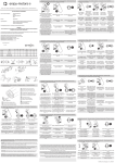
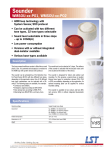
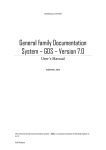
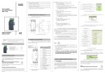
Observations concerning the operational safety:
· All operations concerning transport, installation and commissioning
as well as maintenance must be carried out by qualified, skilled
personnel, and national regulations for the prevention of accidents
must be observed.
· Before switching the transducer on, one must check the correctness
of connections to the network.
· The removal of the transducer casing during the guarantee contract
period causes its cancellation.
· The device is destined to be installed and used in industrial electromagnetic environment conditions.
· A switch or a circuit-breaker should be located near the device,
easy accessible by the operator and suitably marked.
In the safety service scope, the transducer meets to requirements of
the EN 61010-1 standard.
2. BEZPIECZEÑSTWO U¯YTKOWANIA
2. OPERATIONAL SAFETY
1
1. transducer P30U ................................ 1 pc
2. quick start manual .............................. 1 pc
3. guarantee card ................................... 1 pc
4. plug with screw terminals ................. 4 pcs
4
1. TRANSDUCER
ZESTAW REGULATORA
1.
SET
www.lumel.com.pl/en/ web site.
Note! The full version of the user’s manual is inserted in the
QUICK START MANUAL
TRANSDUCER OF
TEMPERATURE AND
STANDARD SIGNALS
P30U TYPE
3. TRANSDUCER DIMENSIONS AND FIXING WAY
Fig. 3. Transducer configuration by LPCon program.
Transmission of
the configuration
through the RS-485
interface
The transducer configuration can be carried out by the free LPCon
program available on our website www.lumel com.pl/en/ or through the
transducer menu acc. to the user’s manual.
5. TRANSDUCER CONFIGURATION
Fig.2. Transducer connection diagram
4. CONNECTION DIAGRAMS
Fig.1. Dimensions and fixing way of transducer P30U.
Lock
The P30U transducer is adapted to be mounted on a 35 mm rail acc. to
EN 60715.
Service
parameters
Settings
Service
Archiving
parameters
Settings
Archive
Parameters of
RS485 interface
Settings
Modbus
Outputs
parameters
Settings
Output
Parameters of
alarm 2
Settings
Alarm 2
Parameters of
alarm 1
Settings
Alarm 1
Display
parameters
Parameters of
the individual
characteristic
Settings
Display
Settings
Ind.Char
Parameters of
main input
Settings
Input
X1
Point No
AnIn Hi
AnOut Lo
Security
Enter the
password
ParFact
Write
standard
parameters
Setting the
actual time
Setting the
actual date
Date
Lower
threshold of
archiving
Time
OverLoAr
Ar.Mode
Archiving type
Param.Ar
Type of value
which will turn
on conditional
archiving
Selection
of archived
volumes
Baud rate
Arch.Val
Register
address to be
read out
(Master mode)
BaudRate
ModeUnit
Kind of frame
Reg.No
Lower threshold
of the output
Device
address
Upper threshold
of the input
Upper
threshold of
alarm 2
OverHiA1
Address
AnIn Lo
Lower threshold
of the output
Type of
alarm 2
Param.An
OverLoA2
Type A2
Param.A2
Type of input
quantity of
alarm 2
Type of input
quantity for the
analog output
OverHiA2
Lower
threshold of
alarm 1
Type of
alarm 1
Lower
threshold of
alarm 2
Upper
threshold of
alarm 1
OverLoA1
Type A1
Param.A1
Type of input
quantity of
alarm 1
Upper threshold
of display
range
Lower threshold
of display
range
Unit
Diplayed
unit
Minimum
decimal point
Over Hi
....
First point of
the individual
characteristic
Point y.
Over Lo
Y1
Comp.Val
Manual
compensation
value
Compens.
Compensation
type
Number of
points of the
individual
characteristic
DecimalP
First point of
the individual
characteristic.
Point x.
AvgTime
Averaging time
of measured
value
Input
Measured
value type
7.
PRACY
6. ROZPOCZÊCIE
STARTING TO WORK
No.ofErr
Math Fun
DispTest
Test of the LCD
display and
diodes
Selection of
menu language
Language
Upper
threshold of
archiving
Automatic
change of
time - summer/winter and
inversely
Ar.Erase
Erasing of internal archive
Ar.Time
Archiving time
OverHiAr
AutoTime
Read out
interval (Master
mode)
Interval.
Lower overflow
of input
Type of read out
register (Master
mode)
TypeReg
Overflow
options turning
on
Number of read
out registers
(Master mode)
No.ofReg.
Upper threshold
of the output
OvrOutLo
OvrOutHi
Value expected
on the output
during upper
overflow of input
Fig. 5. Programming matrix.
Param.SD
Fulfilment percentage of internal archive, which will turn on
automatic record on
the SD/SDHC card
Rec.ToSD
Value expected on
the output during
lower overflow of
input
Manual copying
of internal
archive to the
SD/SDHC card
Maximal time
of reply (Master
mode)
AnswTime
Upper overflow
of input
OvrIn Hi
Support
of alarm 2
signaling
Delay of
reswitching on
the alarm 2
Delay of
switching off the
alarm 2
OvrIn Lo
SgKeepA2
OnLockA2
DlyOffA2
DlyOnA2
Delay of switching on the
alarm 2
OverServ
Support
of alarm 1
signaling
Delay of
switching off the
alarm 1
AnOut Hi
SgKeepA1
Delay of
reswitching on
the alarm 1
DlyOffA1
DlyOnA1
Disp.Reg.
Delay of switching on the
alarm 1
Backlight
intensity of LCD
display
Last point of
the individual
characteristic
Bckl.Int.
Y21
Operation of
mathematical
function on the
measured value
Number of register displayed on
the lower line of
the display
OnLockA1
Backlight time
of display
Last point of
the individual
characteristic
Bcklight
Admissible
number of incorrect requests for
the input RS485
Master
X21
Fig. 4. Algorithm of the P30U transducer service
SD/SDHC card full
Display the maximal value
Display the minimal value
pulsating
permanent
Fig.6 Data switching scheme displayed on display lower line.
27,532
0,0000
27,532
27,532
05-07-11
27,532
18:23:35
27,532
%
0923-611-194
2
-55...185 oC
-50...180 oC
Cu100
Voltage mV
-65...185 oC
-60...180 oC
Ni1000-LG
-80...80 mV
-210...210 mV
-75...75 mV
-200...200 mV
-6...21 mV
-65...185 oC
-60...180 oC
Ni100-LG
-5...20 mV
-65...155 oC
-60...150 oC
Ni1000
-205...255 oC
-200...250 oC
-65...185 oC
-205...855 oC
-200...850 oC
-205...855 oC
-205...185 oC
-200...180 oC
-60...180 oC
-205...855 oC
-200...850 oC
-205...605 oC
-200...850 oC
Ni100
Pt1000
Pt500
Pt250
-200...600 oC
Resistance 5500 W
0...2050 W
0...5550 W
0...2000 W
Resistance 2000 W
0...420 W
-24...24 mA
-205...855 oC
0...400 W
Resistance 400 W
0...5500 W
-20...20 mA
Current
-28...28 V
-12...12 V
Maximal
measuring
range
2 GB
1 GB
4
4
1
1
2
1
2
1
2
4
3
3
3
4
5
2
2
4
10
10
5
Coefficant k
Table 2
Capacity
-200...850 oC
-24...24 V
Pt100
-10...10 V
Nominal
measuring
range
Voltage 24V
Input type
Voltage 10V
Inputs:
10. TECHNICAL DATA
0923-611-193
1
Order code
0.1
Accuracy
class
Table 3
As additional accessory to the transducers with SD/SDHC memory card
option (version P30U-X1XXXXXX) can be ordered the industrial SD card
with the capacity adapted to the user needs, according to the table below.
RS-485 monitoring mode provides
possibility of monitoring the frames
sent between Master and Slave in
RS-485 network. Value of any register read by Master from Slave can
be displayed on transducer’s screen. In this mode there is no possibility of reading by Master device
any data from the transducer.
1
1
2
2
1
1
1
2
2
1
2
1
0.5
0.1
0.5
0.1
0.5
0.1
Table 3
backlighted LCD, 2 x 8 signs
35 mm rail acc. to EN 60715
300 V for supply circuit and 50 V for
other circuit
<2000 m
basic,
III,
2,
Remark: Detailed technical data available in the service manual
· altitude above sea level
Safety Requirements:
acc. to EN61010-1
· isolation between circuits:
· installation category
· pollution level
· maximal phase-to-hearth
voltage:
Reference and rated operating conditions
- supply voltage
85...253 V d.c./a.c.(40...400 Hz)
or 20...40 V a.c.(40...400 Hz), 20...60 V d.c.,
- ambient temperature
-25...23...+55 oC
- storage temperature
-30...+70 oC
- relative humidity
25...95 % (condensation inadmissible)
- working position
any
Readout field:
Fixing way:
Overall dimensions: 120 x 45 x 100 mm
Power consumption: < 5 VA
- processing time < 200 ms
- relay - 1 or 2 relays; NO voltageless contacts - maximal load 5A 30V d.c.,
250V a.c.
- digital – RS-485 interface (Modbus RTU)
- class of analog output 0.1;
Outputs:
- analog, programmable, galvanically isolated current (0/4...20 mA, load
resistance £ 500 W) or voltage (0...10 V, load resistance ³ 500 W),
Monitor RS485
Master RS485
In the Master RS-485 mode the
transducer can read out one device with implemented Modbus protocol with RS-485 interface. In this
mode there is no possibility to connect master device to transducer.
390...1820 oC
400...1800 oC
Thermocouple B
-55...1765 oC
0...1760 oC
o
-210...1010 C
-50...280 oC
o
-200...1000 C
-240...1350 C
-40...260 oC
o
o
-200...1300 C
-50...450 C
-20...420 C
SD/SDHC card mounted and ready to work
9. ACCESSORIES
-55...1775 oC
0...1760 oC
SD/SDHC card mounted and ready to be
removed
Karta SD/SDHC card protected against
record
permanent
pulsating
pulsating
-280...1382 oC
-200...1370 oC
o
-20...420 oC
0...400 oC
o
-220...1210 oC
-200...1200 oC
-210...410 oC
Thermocouple R
Thermocouple E
Thermocouple N
Thermocouple S
Thermocouple K
Thermocouple J
-20...420 oC
0...400 oC
-200...400 oC
permanent
The P30 tranducers are standard equipped with internal memory
designed to storage the data, registered by transducer. Downloading
of archival data from internal memory can be done using memory
card SD/SDHC (option) or by using RS485 interface. For the transducers with SD/SDHC memory card option there is possibility of fast
rewriting the archive to the SD/SDHC card after pressing the buttons
and
.
combination:
8. ARCHIVING
Thermocouple T
Meaning
Display
method
Display lower line in the P30U transducer is multifunctional. After pressing
or
, the lower line functions are periodically switthe button
ched: unit, time, date, bargraph indicating the percent value of analog
output, the value of any register in the transducer.
Symbol
Table 1
P30U transducer is equipped with backlighted LCD display, consisted
of two lines, 8 signs each. The top row is used to display measured value (floating point format, 5 digits) and symbol of SD/SDHC card status.
After pressing button
or
symbol and value of maximal or minimal value will be displayed.
7. DISPLAY FORMAT
1
2
00
XX
P
E
X XX X
0
1
X
X
NOTES
Code P30U-111100E0 means transducer execu!on with current output, slot for
SD/SDHC card, with 2 alarm relays, 85..253 V a.c. / d.c. (40...400 Hz) power supply,
standard version, English language, without extra requirements.
Order example:
* a#er agreeing with the manufacturer
P30U - X XX X
Analog output:
current (0/4...20 mA)
1
voltage (0...10 V)
2
SD/SDHC card:
without slot for SD/SDHC card
0
with slot for SD/SDHC card
1
Addi!onal output:
NO relay, 5 A 30 V d.c., 250 V a.c.
1
supply 24 V d.c. / 30 mA
2
Supply:
85...253 V a.c./d.c.
20...40 V a.c., 20...60 V d.c.
Version:
standard
custom-made*
Language:
Polish
English
Acceptance tests:
without extra requirements
with an extra quality inspec!on cer!ficate
according to customer’s request*
11. ORDERING CODES
P30U-09/2