1
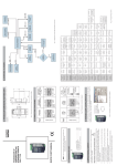
DATA LOGGER WITH WWW SERVER SM61 TYPE · Before switching the data logger on, one must check the correctness of connections of the network. · Before the remove of the casing one should switch off data logger power and measurement circuits. · The device is destined to be installed and used in industrial electro magnetic environment conditions. · A switch or a circuit - breaker should be located near the device, easy accessible by the operator and suitable marked. 3. DIMENSIONS AND FIXING WAY The SM61 data logger is fixing on rail bracket 35 mm. Dimensions and fixing way are shown at pic. 1. Data logger SM61 has four communication interfaces:: 1. PORT 1 - serial interface: · purpose - communication with Master device, · bus - RS-232, RS-485, · terminals - 14, 15, 16 (RS-485) and 12, 13, 14 (RS-232), · galvanically isolated from rest of the system, · maximum length of bus depends on the speed of transmission (for high speeds of up to severals tens of meters, for small, eg. 9600 bit/s to about 1.2 km). 2. PORT 2 - serial interface: · purpose - communication with Slave device, · bus - RS-485, · terminals - 5, 6, 7, 8, · galvanically isolated from rest of the system, · maximum length of bus depends on the speed of transmission (for high speeds of up to severals tens of meters, for small, eg. 9600 bit/s to about 1.2 km). Note: The full version of the user’s manual is inserted in the www.lumel.com.pl/en/ web site. 1. DATA ZESTAW REGULATORA 1. LOGGER SET 1. data logger SM61........................... 1 pc 2. quick start manual...........................1 pc 3. guarantee card............................... 1 pc 4. CD with the software and user’s manual..................................1 pc Power and external inputs should be connect according to the pic. 2 and table 1 in which is described destiny of the individual terminals in SM61 data logger. Port 1 on Supply dependent depend on the code version (85...230...253 V a.c./d.c. or 20...24...50 V a.c./d.c.) Table 1 Terminal 1 3 2. OPERATIONAL SAFETY 4 Symbols placed in the manual means: Especially important, you should know before you connect the data logger. Failure to follow the remarks could lead to damage of the data logger. LAN Notice: The removal of the data logger casing during the guarantee contract period lead to its cancellation. In the safety service scope, the meter meets to requirements of the EN 61010-1 standard. or INPUT · All operations concerning transport, installation and commissioning as well as maintenance must be carried out by qualified, skilled personnel, and national regulations for the prevention of accidents must be observed. Port 2 Pic.2. Electrical connections of SM61 data logger. Configuration of Ethernet settings Configuration of serial port settings Pic.3. Left menu of SM61Config After right - click on the selected device from the list a new menu shown in pic. 4. Pic.4. This menu is shown after right-click. Selecting option Change IP brings up a window allowing the configuration of the following settings as in pic. 5. IP address Subnet mask Gateway on/off DHCP After connection device to Ethernet network it is able to configure settings using HTTP protocol or Modbus TCP. The data logger set include CD with USB driver and software SM61Config, which is used to find devices in Ethernet network and configure them by Modbus RTU (USB) or Modbus TCP (Ethernet) protocol. 4. CONNECTION DIAGRAMS 2 Observations concerning the operational safety: The category of twisted pair according to European norm EN 50171 minimal: class D (category 5) – for fast local network, includes applications which uses the frequency band up to 100 MHz. Description of the connection is shown at table 2. · EIA/TIA 568A for both connectors in simple connections SM61 to a hub or switch, · EIA/TIA 568A for first connector and EIA/TIA 568B for second connector in connection with crossover (connection SM61 to a computer). Pic.1. Dimensions and fixing way Shown the list of found modules 3. USB - serial interface: · protocol of data exchange: Modbus RTU, · purpose - device configuration, · connection - mini USB. 4. LAN: · protocol of data exchange: Modbus TCP, · purpose - device configuration, · allow to connect device to Ethernet network, · connection - RJ-45. USER’S MANUAL QUICK START 7. ROZPOCZÊCIE PRACY Description Input line (positive terminal input 1) or line of alarm 1 Input line (negative terminal input 1) or line of alarm 1 Input line (positive terminal input 2) or line of alarm 2 Input line (negative terminal input 2) or line of alarm 2 5 GND line 6 Line B (RS-485) 7 Line A (RS-485) 8 Line 5 V d.c. 9 Line + supply 10 Line - supply 11 not used 12 Output TxD (RS-232) 13 Input RxD (RS-232) 14 Line GND 15 Line A (RS-485) 16 Line B (RS-485) Restart module after set configuration FTP server data port FTP server command port Notice: To get full resistance of data logger on electromagnetic interference one should follow these rules: · do not supply the data logger from the network which is near pulse noise generators (inverters) and do not use common with them grounding circuits, · use network filters, · all shields should be grounded or connected to the protective unit, one sided the nearest to the data logger, · use the general rule, the wires leading different signals should be carried out in the greatest distance from each other (no less then 30 cm), the intersection of these beams is performed at 90o. 5. DATA LOGGER CONFIGURATION 5.1. STARTING TO WORK The device need to set basic information about IP protocol at the first start (IP address, subnet mask, gateway). Needed information should be given from local network administrator in which device will be joined. Software SM61Config let the user configure settings using USB protocol or using Ethernet network. In the case of first configuration using Ethernet network please open the SM61Config application and show the list of found data loggers by choosing List of SM61 devices from the left menu as it’s shown in pic. 3. Web server port Modbus TCP port Pic.5. Change of settings IP After making changes please left - click on OK to close a window and save changes to the device. Configuration can be done also by USB. To connect with the device by UBS, please select from the software menu Options and choose type of communication as it’s shown at pic. 6. Pic.6. Selection of the type of communication. Then please go to the configuration by selection the option from left menu (see fig. 3). Selecting the option allow change the configuration. After changing the configuration one should save it and restart the device to set the new configuration. Notice: After changing the parameters the device should be reset. Language is changing by selection Option -> Language and then selection language from available positions. After that close the application and open again. Notice: For proper working of web site one need to have the browser with JavaScript enabled and compatible with XHTML 1.0 (all popular browsers, Internet Explorer version minimum 8). Access to the server is getting by writing IP address of the data logger in web browser e. g.: http://192.168.1.1 (where 192.168.1.1 is default IP address of the data logger). After loading the site the window with log in will show up. One should enter user’s login and password. The data logger has one default user: - login: root - password: dbps For security purpose after first start of browser the login and password should be changed to different than default, for security. To change login and password one should left-click on Administration and then left-click on Users from the menu. Right-click on user Administrator from the list of users and then left-click on Edit cause the window which allows to set changes. The structure of site menu is shown on pic. 7. 6. FTP CLIENT The SM61 allow communication by use of FTP protocol. Access to the file resources is possible through standard FTP client program. To connect to the device via an FTP client should be used: · IP address of the data logger (configured as shown in point 5.1 pic. 5), · FTP server command port (configured as shown in point 5.1 pic. 5), · FTP server data port (configured as shown in point 5.1 pic. 5), · login and password - default user (the same for the web site): login: root password: dbps Catalogs contains: · DATA - contains files with archival data, · LOG - contains files with logs, · SYSTEM - contains files with configuration, · WWW - contains files with web site. RATED OPERATING CONDITIONS 8. REGISTER MAP Map of the group records Type of value Description 4000 – 4615 16 bits registers that contain the device configuration, registers for reading and writing 16 bits registers only for reading, contain the static parameters and information about device 16 bits registers only for reading, contain the values from connected devices, values are placed one after the other from channel 1 to 100 8000 – 13000 20...24...50 V a.c./d.c. or 85...230...253 V a.c./d.c. 40...50/60...440 Hz Power consumption: < 4 VA Ambient temperature: work: 0...23...55o C storage: -20...70o C Relative humidity: < 95% inadmissible condensation Operating position: any External magnetic field: < 400 A/m Table 2 Range of addresses 5000 – 5455 Supply voltage: Notice: For the file transfer only one connection at the same time is possible. Copying should be done in binary mode. SAFETY AND COMPATIBILITY REQUIREMENTS In the data logger SM61 data are placed in 16 bits registers. Electromagnetic compatibility: - noise immunity acc. to EN 61000-6 -2 - noise emission acc. to EN 61000-6-4 Installation category: III Pollution grade: 2 Maximal phase-to-earth operating voltage - for the supply circuit - for the measuring input: 7. INTERNAL ARCHIVE Homepage Data presentation - channel values - synoptic map Configuration - channels - alarms - synoptic map - serial port - Ethernet Administration - general - date and time - users Pic.7. Structure of the menu The menu items shown on pic. 7: a) Data presentation - include following elements: - channels values - presents actual values from device (in table and in figure), - synoptic map - presents actual values from device on synoptic map. b) Configuration - include following elements: - channels - configuration of all channels and channels’ values, - alarms - configuration of both alarms, - synoptic map - configuration of synoptic map, - serial port - configuration of serial port settings, - Ethernet - configuration of Ethernet settings. c) Administration - include following elements: - general - set name and description of the device, set number of records in archive file and set archive mode, set starting page, - date and time - configuration of date and time in the device, - users - set user login and password and set the type of user account. Notice: After changing the parameters the device should be reset. Please remember, the configuration must be done before data presentation. The SM61 data logger enables to storage data read from Slave type devices. The parameter that is recorded to an archive file is a current data read from channel’s value or current data read and calculate using mathematical operations. Channel should be set on archive mode or full mode. Archive files are create in database DBF format in catalog DATA and sub - folder with name of year in which was created. Name of archive file include date and hour of creation, in form: MMDDHHMinMin.DBF. Files contains definite number of records and always have 31 columns. The files in row always have the following meaning: - INDEX_NO - index number of record in file; - CHAN_NO - channel number; - VAL_TYP - type of value, according to the type of register (char, unsigned char, short, unsigned short, long, unsigned long, float1234, float4321), - VAL_STAT - value status (where 1 means ok, and 0 means error or timeout), - DATE - date of recorded data, - TIME - time of recorded data ( hour, minute, second), - VAL_1,...,VAL_25 - recorded value. Archive files can be read, copy and delete. When file is deleted, new one is created with actual archive settings. The downloading archive data from the data logger can be done using FTP client. To download archive file you need to connect to the device via FTP client (point 6 FTP Client). 10. ORDERING CODES 9. TECHNICAL DATA Table 3 COMMUNICATIONS INTERFACE Interface Port 1:RS-485, RS-232, Port 2: RS485 USB Function communication with PC and HMI panels and other Master devices communication with Slave devices device configuration device communication and configuration Ethernet 10/100Base-T Baud rate 1200, 2400, 4800, 9600, 19200, 38400, 57600, 115200 bit/s 115200 bit/s 10, 100 Mbit/s Information unit 1 start bit, 7 or 8 data bits, 1 odd/even parity bit, 1 or 2 stop bits 1 start bit, 8 data bits, 1 even parity bit, 1 stop bit TCP/UDP Transmission protocol Remarks max. cable lenght: up to 2 m max. cable lenght: up to 100 m EXTERNAL FEATURES Weight: < 0.25 kg Dimensions: 45 x120 x 100 mm Protection grade (acc. to EN 60529): Fixing: The way of coding is given in the table 4. SM61 - ensured by the housing: IP40 from the terminal side: IP20 on a 35 mm rail Table 4 X X XX X X Supply voltage: 85...253 V a.c./d.c. 1 20...50 V a.c./d.c. 2 Input/Output: 2 relays outputs 1 2 binary inputs 2 Version: standard 00 custom-made* XX Language: Polish P English E other* X Acceptance tests: without extra requiremnt 0 with an extra Quality Inspection certificate 1 acc. to customer’s request* X TCP/IP, HTTP, ICMP, DHCP, ARP, Modbus TCP, FTP MODBUS RTU max. cable lenght depends on the baud rate 300 V 50 V * only after agreeing with the manufacturer Order exapmle: The code SM61 - 1-2-00-E-1 means data logger SM61: 1 - with supply voltage 85...253V a.c./d.c., 2 - with 2 binary inputs, 00 - standard version, E - user’s manual in english, 1 - with an extra Quality Inspection certificate. SM61-09/2 5.2. WEB BROWSER To access to the server the device must be connected to an Ethernet network operating in accordance with TCP/IP protocol. At the first start data logger require to set necessary IP information such as: IP address, subnet mask, gateway. Point 5.1 shows how to set configuration at first start.


![Manual[DOWNLOAD]](http://vs1.manualzilla.com/store/data/005897454_1-7b43247b19e54aa42c3777609ebafaf8-150x150.png)