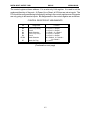
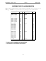
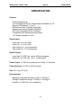
1
ACCES I/O PRODUCTS INC
10623 Roselle Street, San Diego CA 92121
Tel. (619)550-9559 FAX (619)550-7322
)550-7322
DIGITAL INPUT/OUTPUT CARD
IOD-24E
USER MANUAL
File: MIOD-24E.B2c
DIGITAL INPUT/OUTPUT CARD
IOD-24E
USER MANUAL
NOTICES
The information in this document is provided for reference only. ACCES does not assume
any liability arising out of the application or use of the information or products described
herein. This document may contain or reference information and products protected by
copyrights or patents and does not convey any license under the patent rights of ACCES,
nor the rights of others.
IBM PC, PC/XT, and PC/AT are registered trademarks of the International Business
Machines Corporation.
Printed in USA. Copyright 1994 by ACCES I/O PRODUCTS INC, 10623 Roselle Street,
San Diego,CA 92121. All rights reserved.
i
DIGITAL INPUT/OUTPUT CARD
IOD-24E
USER MANUAL
TABLE OF CONTENTS
INSTALLATION . . . . . . . . . . . . . . . . . . . . . . . . . . . . . . . . . . . . . . . . . . . . . . . . . . . . . iv
CD INSTALLATION . . . . . . . . . . . . . . . . . . . . . . . . . . . . . . . . . . . . . . . . . . . . iv
3.5-INCH DISKETTE INSTALLATION . . . . . . . . . . . . . . . . . . . . . . . . . . . . . . iv
DIRECTORIES CREATED ON THE HARD DISK . . . . . . . . . . . . . . . . . . . . . . v
INSTALLING THE CARD . . . . . . . . . . . . . . . . . . . . . . . . . . . . . . . . . . . . . . . 1-1
FUNCTIONAL DESCRIPTION . . . . . . . . . . . . . . . . . . . . . . . . . . . . . . . . . . . . . . . . .
FEATURES . . . . . . . . . . . . . . . . . . . . . . . . . . . . . . . . . . . . . . . . . . . . . . . . .
APPLICATIONS . . . . . . . . . . . . . . . . . . . . . . . . . . . . . . . . . . . . . . . . . . . . . .
DESCRIPTION . . . . . . . . . . . . . . . . . . . . . . . . . . . . . . . . . . . . . . . . . . . . . . .
BLOCK DIAGRAM . . . . . . . . . . . . . . . . . . . . . . . . . . . . . . . . . . . . . . . . . . . .
2-1
2-1
2-1
2-1
2-2
OPTION SELECTION . . . . . . . . . . . . . . . . . . . . . . . . . . . . . . . . . . . . . . . . . . . . . . . . 3-1
OPTION SELECTION MAP . . . . . . . . . . . . . . . . . . . . . . . . . . . . . . . . . . . . . 3-2
ADDRESS SELECTION . . . . . . . . . . . . . . . . . . . . . . . . . . . . . . . . . . . . . . . . . . . . . . 4-1
STANDARD ADDRESS ASSIGNMENTS FOR 286/386/486 . . . . . . . . . . . . . 4-1
SOFTWARE . . . . . . . . . . . . . . . . . . . . . . . . . . . . . . . . . . . . . . . . . . . . . . . . . . . . . . . 5-1
PROGRAMMING . . . . . . . . . . . . . . . . . . . . . . . . . . . . . . . . . . . . . . . . . . . . . . . . . . .
DEVELOPING YOUR APPLICATION SOFTWARE . . . . . . . . . . . . . . . . . . .
REGISTER ADDRESS ASSIGNMENTS . . . . . . . . . . . . . . . . . . . . .
CONTROL REGISTER BIT ASSIGNMENTS . . . . . . . . . . . . . . . . . .
PROGRAMMING EXAMPLE . . . . . . . . . . . . . . . . . . . . . . . . . . . . . . . . . . . .
6-1
6-1
6-1
6-2
6-3
CONNECTOR PIN ASSIGNMENTS . . . . . . . . . . . . . . . . . . . . . . . . . . . . . . . . . . . . . 7-1
SPECIFICATION . . . . . . . . . . . . . . . . . . . . . . . . . . . . . . . . . . . . . . . . . . . . . . . . . . . . 8-1
WARRANTY . . . . . . . . . . . . . . . . . . . . . . . . . . . . . . . . . . . . . . . . . . . . . . . . . . . . . . . 9-1
PPI DATA SHEETS . . . . . . . . . . . . . . . . . . . . . . . . . . . . . . . . . . . . . . . . . . . . . . . . . . A-2
ii
DIGITAL INPUT/OUTPUT CARD
IOD-24E
USER MANUAL
INSTALLATION
The software provided with this card is contained on either one CD or multiple diskettes
and must be installed onto your hard disk prior to use. To do this, perform the following
steps as appropriate for your software format and operating system. Substitute the
appropriate drive letter for your CD-ROM or disk drive where you see d: or a:
respectively in the examples below.
CD INSTALLATION
DOS/WIN3.x
1.
Place the CD into your CD-ROM drive.
2.
Type d:K to change the active drive to the CD-ROM
drive.
3.
Type installK to run the install program.
4.
Follow the on-screen prompts to install the software for
this card.
WIN95/98/NT
1.
Place the CD into your CD-ROM drive.
2.
The CD should automatically run the install program after 30 seconds.
If the install program does not run, click START | RUN and type
d:install, click OK or press K.
3.
Follow the on-screen prompts to install the software for this card.
4.
Click the “Go to ACCES Web” button to check for software updates.
3.5-INCH DISKETTE INSTALLATION
As with any software package, you should make backup copies for everyday use and store
your original master diskettes in a safe location. The easiest way to make a backup copy
is to use the DOS DISKCOPY utility.
In a single-drive system, the command is:
diskcopy a: a:K
You will need to swap disks as requested by the system.
In a two-disk system, the command is:
diskcopy a: b:K
iii
DIGITAL INPUT/OUTPUT CARD
IOD-24E
USER MANUAL
This will copy the contents of the master disk in drive A to the backup disk in drive B.
To copy the files on the master diskette to your hard disk, perform the following steps.
1.
Place the master diskette into a floppy drive
2.
Change the active drive to the drive that has the diskette installed. For
example, if the diskette is in drive A, type a:K.
3.
Type installK and follow the on-screen prompts.
DIRECTORIES CREATED ON THE HARD DISK
The installation process will create several directories on your hard disk. If you accept the
installation defaults, the following structure will exist.
[CARDNAME]
Root or base directory containing the SETUP.EXE setup program used
to help you configure jumpers and calibrate the card.
DOS\PSAMPLES: A subdirectory of [CARDNAME] that contains Pascal samples.
DOS\CSAMPLES: A subdirectory of [CARDNAME] that contains “C” samples.
WIN32\language
Subdirectories containing samples for Win95/98 and NT.
WinRisc.exe: A Windows dumb-terminal type communication program
designed for RS422/485 operation. Used primarily with
REMOTE ACCES Data Acquisition Pods and our RS422/485
serial communication product line. Can be used to say hello to
an installed modem.
ACCES32:
This directory contains the Windows 95/98/NT driver used to provide
access to the hardware registers when writing 32-bit Windows
software. Several samples are provided in a variety of languages to
demonstrate how to use this driver. The DLL provides four functions
(InPortB, OutPortB, InPort, and OutPort) to access the hardware.
This directory also contains the device driver for Windows NT,
ACCESNT.SYS. This device driver provides register-level hardware
access in Windows NT. Two methods of using the driver are available, through ACCES32.DLL (recommended) and through the
DeviceIOControl handles provided by ACCESNT.SYS (slightly faster).
SAMPLES: Samples for using ACCES32.DLL are provided in this
directory. Using this DLL not only makes the hardware
programming easier (MUCH easier), but also one source
file can be used for both Windows 95/98 and
iv
DIGITAL INPUT/OUTPUT CARD
IOD-24E
USER MANUAL
WindowsNT. One executable can run under both
operating systems and still have full access to the
hardware registers. The DLL is used exactly like any
other DLL, so it is compatible with any language capable
of using 32-bit DLLs. Consult the manuals provided with
your language’s compiler for information on using DLLs
in your specific environment.
VBACCES:
PCI:
This directory contains sixteen-bit DLL drivers for use with
VisualBASIC 3.0 and Windows 3.1 only. These drivers provide
four functions, similar to the ACCES32.DLL. However, this DLL
is only compatible with 16-bit executables. Migration from 16bit to 32-bit is simplified because of the similarity between
VBACCES and ACCES32.
This directory contains PCI-bus specific programs and information. If
you are not using an ACCES PCI card, this directory will not be
installed.
SOURCE:
A utility program is provided with source code you can
use to determine allocated resources at run-time from
your own programs in DOS.
PCIFind.exe A utility for DOS and Windows to determine what base
address and IRQ are allocated to installed PCI cards.
This program runs two versions, depending on the
operating system. Windows 95/98/NT displays a GUI
interface, and modifies the registry. When run from
DOS or Windows3.x, a text interface is used. For
information about the format of the registry key, consult
the card-specific samples provided with the hardware.
In Windows NT, NTioPCI.SYS runs each time the
computer is booted, thereby refreshing the registry as
PCI hardware is added or removed. In Windows
95/98/NT PCIFind.EXE places itself in the bootsequence of the OS to refresh the registry on each
power-up.
This program also provides some COM configuration
when used with PCI COM ports. Specifically, it will
configure compatible COM cards for IRQ sharing and
multiple port issues.
v
DIGITAL INPUT/OUTPUT CARD
IOD-24E
USER MANUAL
WIN32IRQ: This directory provides a generic interface for IRQ handling in
Windows 95/98/NT. Source code is provided for the driver, greatly
simplifying the creation of custom drivers for specific needs. Samples
are provided to demonstrate the use of the generic driver. Note that
the use of IRQs in near-real-time data acquisition programs requires
multi-threaded application programming techniques and must be
considered an intermediate to advanced programming topic. Delphi,
C++ Builder, and Visual C++ samples are provided.
Findbase.exe
DOS utility to determine an available base address for ISA bus , nonPlug-n-Play cards. Run this program once, before the hardware is
installed in the computer, to determine an available address to give
the card. Once the address has been determined, run the setup
program provided with the hardware to see instructions on setting the
address switch and various option selections.
Poly.exe
A generic utility to convert a table of data into an nth order polynomial.
Useful for calculating linearization polynomial coefficients for
thermocouples and other non-linear sensors.
Risc.bat
A batch file demonstrating the command line parameters of
RISCTerm.exe.
RISCTerm.exe
A dumb-terminal type communication program designed for
RS422/485 operation. Used primarily with REMOTE ACCES Data
Acquisition Pods and our RS422/485 serial communication product
line. Can be used to say hello to an installed modem. RISCTerm
stands for Really Incredibly Simple Communications TERMinal.
vi
DIGITAL INPUT/OUTPUT CARD
IOD-24E
USER MANUAL
INSTALLING THE CARD
Before installing the card carefully read the ADDRESS SELECTION and OPTION
SELECTION Sections of this manual and configure the card according to your requirements. Use the special software program called SETUP provided on the CD with the
card. It supplies visual aids to configure all areas of the board.
Be especially careful with address selection. If the addresses of two installed functions
overlap, you will experience unpredictable computer behavior. If unsure what locations
are available, you can use the FINDBASE program provided to locate blocks of
available addresses.
To install the card:
1. Remove power from the computer.
2. Remove the computer cover.
3. Remove blank I/O backplate.
4. Install jumpers for selected options. See OPTION SELECTION
5. Select the base address on the card. See ADDRESS SELECTION
6. Install the card in an I/O expansion slot.
7. Inspect for proper fit of the card and cables and tighten screws.
8. Replace the computer cover.
A 50-pin connector is provided on the mounting bracket for input/output connections.
To ensure that there is minimum susceptibility to EMI and minimum radiation, it is
important that the card mounting bracket be properly screwed into place and that there
be a positive chassis ground. Also, proper EMI cabling techniques (cable connect to
chassis ground at the aperture, shielded twisted-pair wiring, etc) must be used for the
input and output wiring.
1-1
DIGITAL INPUT/OUTPUT CARD
IOD-24E
USER MANUAL
FUNCTIONAL DESCRIPTION
FEATURES
24 Input/Output Lines
Four and Eight Bit Groups Independently Selectable for I/O
Bi-Directional Data Transfers Supported.
Supports PPI Modes 0, 1, and 2
Interrupt and Interrupt-Disable Capability
OPTO-22 Compatible 50-Pin Connector
Compatibility with Module Mounting Racks
+5 V Supply Available to User
APPLICATIONS
Automatic Test Systems
Security Systems, Energy Management
Relay Monitoring and Control
Robotics
Parallel Data Transfer to PC
Sensing Switches or Signals, or TTL, DTL, CMOS Logic
DESCRIPTION
Model IOD-24E is an economical 24-bit parallel digital input/output card. It is half size and
can be installed in either long or short expansion slots of IBM PC/XT/AT or compatible
computers.
The card contains a Programmable Peripheral Interface chip type 8255-5 (PPI) which
provides computer interface to 24 digital I/O lines. Three 8-bit ports A, B, and C can be
configured to function as either inputs, or as output latches. Port C can be also configured
as four inputs and four output latches. All 8255-5 PPI modes are supported by the
IOD-24E.
Two I/O lines can be used for interfacing User Interrupts to the computer. Interrupts are
buffered and are enabled by a digital input line. You can use Interrupt levels #2 through
#7.
Input/Output wiring connections are via a 50-pin connector at the rear of the computer.
This provides compatibility with industry-standard module mounting racks from OPTO-22,
Gordos, Potter & Brumfield, etc. Also, the connections are compatible with ACCES model
STA-50 Screw Terminal Accessory Boards. Every second conductor of the flat cable is
grounded to minimize the effect of crosstalk between signals.
2-1
DIGITAL INPUT/OUTPUT CARD
IOD-24E
USER MANUAL
If needed for external circuits, +5 VDC power is available at connector pin 49.
The IOD-24E occupies four consecutive bytes of I/O address space. The base address is
selectable via a DIP switch anywhere within the range of 000-3FF hex. If in doubt how to
select a base address, check your computer reference manual. For additional information
about setting the base address of IOD-24E, see the ADDRESS SELECTION section of this
manual and the setup software program supplied with the card.
Utility software is provided with the IOD-24E card. This software includes an illustrated
setup program, and sample programs in Quickbasic, C and Pascal.
IOD-24E BLOCK DIAGRAM
2-2
DIGITAL INPUT/OUTPUT CARD
IOD-24E
USER MANUAL
OPTION SELECTION
Refer to the OPTION SELECTION MAP on the next page, and the setup program on the
CD provided with the card when reading this section of the manual.
SLOT 8
Install this jumper when the card is located in a short slot of the host computer.
WAIT
Install this jumper when the host computer clock speed is 8Mhz or more. This will
automatically assert one wait state when the card is addressed.
INT 2,3,4,5,6,7
Install the appropriate jumper to select the interrupt level that the card will be working at.
The foregoing are the only manual setups necessary to use the IOD-24E. Input/Output
selection is done via software by writing to a control register in the PPI as described in the
PROGRAMMING section of this manual.
3-1
DIGITAL INPUT/OUTPUT CARD
IOD-24E
IOD-24E OPTION SELECTION MAP
3-2
USER MANUAL
DIGITAL INPUT/OUTPUT CARD
IOD-24E
USER MANUAL
ADDRESS SELECTION
The IOD-24E Digital Input/Output Card occupies four bytes of I/O address space. The base
address can be selected anywhere within an I/O address range 100-3FC hex in AT's
(except 1F0 through 1F8) and 200-3F0 in XT's. However, two installed options cannot
share the same address. If in doubt where to assign the base address, refer to the
following tables and the FINDBASE program to find an available address for your card.
STANDARD ADDRESS ASSIGNMENTS FOR 286/386/486 COMPUTERS
Hex Range
000-01F
020-03F
040-05F
060-06F
070-07F
080-09F
0A0-0BF
0C0-0DF
0F0
0F1
0F8-0FF
1F0-1F8
200-207
278-27F
2F8-2FF
300-31F
360-36F
378-37F
380-38F
3A0-3AF
3B0-3BF
3C0-3CE
3D0-3DF
3F0-3F7
3F8-3FF
Usage
DMA Controller 1
INT Controller 1, Master
Timer
8042 (Keyboard)
Real Time Clock, NMI Mask
DMA Page Register
INT Controller 2
DMA Controller 2
Clear Math Coprocessor Busy
Reset Coprocessor
Arithmetic Processor
Fixed Disk
Game I/O
Parallel Printer Port 2
Asynchronous Comm'n (Secondary)
Prototype Card
Reserved
Parallel Printer Port 1
SDLC or Binary Synchronous Comm'n 2
Binary Synchronous Comm'n 1
Monochrome Display/Printer
Local Area Network
Color/Graphic Monitor
Floppy Diskette Controller
Asynchronous Comm'n (Primary)
ADDRESS SETUP switches are marked A2-A9. In order to configure the desired address,
assign '1' to all ADDRESS SETUP switches turned OFF, and assign '0' to all ADDRESS
SETUP switches turned ON. These 1's and 0's are a binary representation of the base
address. This binary representation is then converted to hexadecimal.
Switch Identification
A9
A8
4-1
A7
A6
A5
A4
A3
A2
DIGITAL INPUT/OUTPUT CARD
IOD-24E
Address Line Controlled
A9
A8
A7
USER MANUAL
A6
A5
A4
A3
A2
The following example illustrates switch selection corresponding to hex 2DC (or binary 10
1101 11xx). The "xx" represents address lines A1, and A0 used on the card to select
individual registers at the PPI as described in Section 6, PROGRAMMING.
Switch ID
A9
A8
A7
A6
A5
A4
A3
A2
OFF
ON
OFF
OFF
ON
OFF
OFF
OFF
Binary Representation
1
0
1
1
0
1
1
1
Conversion Multipliers
2
1
8
4
2
1
8
4
Setup
Hex Representation
2
D
C
Carefully review the address selection reference Table on the preceding page before
selecting the card address. If the addresses of two installed functions overlap, you will
experience unpredictable computer behavior.
4-2
DIGITAL INPUT/OUTPUT CARD
IOD-24E
USER MANUAL
SOFTWARE
ACCES supplies several programs to support the IOD-24E digital I/O card and, also, to help
you to develop your applications program. The sample programs are in forms suitable for
use with, QuickBASIC, C, and Pascal. The programs as follows:
FINDBASE: Program locates active and available port addresses.
SETUP:
IOD-120 Board Setup Program
BSAMPLES: SAMPLE1
SAMPLE2
CSAMPLES: SAMPLE1
SAMPLE2
EVENT
PSAMPLES: SAMPLE1
EVENT
A Quickbasic program that writes a sequence of
values to Port A and reads and displays the values
in Ports A & B.
A Quickbasic program that displays the bits in Ports
A & B and, when an interrupt occurs, polls those
same bits.
A “C” program that writes a sequence of values to
Port A and reads and displays the values in Ports A
& B.
A "C" program that displays the bits in Ports A & B and,
when an interrupt occurs, polls those same bits.
A sample program demonstrating a security system that
monitors the status of 16 switches and automatically
triggers alarms.
A “Pascal” program that writes a sequence of values
to Port A and reads and displays the values in Ports
A & B.
A sample program demonstrating a security system that
monitors the status of 16 switches and automatically
triggers alarms. These programs are on a CD that
comes with your board.
SETUP
This program is supplied with the IOD-24E as a tool for you to use in configuring the
jumpers on the card. It is a menu-driven program that provides illustrations. You make
simple keystrokes to select functions. The illustrations then show how to place the jumpers.
The setup program is a stand-alone program that can be run at any time. It does not
require the IOD-24E to be plugged into the computer for any part of the setup. The
program is self explanatory with operation instructions and on-line help.
5-1
DIGITAL INPUT/OUTPUT CARD
IOD-24E
USER MANUAL
PROGRAMMING
The IOD-24E is an I/O mapped device that is easily configured from any language and any
language can easily perform digital I/O through the card's ports. This is especially true if
the form of the data is Byte or Word wide. All references to the I/O ports would be in
absolute port addressing. However, a table could be used to convert the Byte or Word data
ports to a logical reference.
DEVELOPING YOUR APPLICATION SOFTWARE
If you wish to gain a better understanding of the software in the previous section, then the
information in the following paragraphs will be of interest to you. Follow the 8255-5 PPI
specification to program the PPI on the IOD-24E card.
The PPI is addressed using address bits A1 and A0 (See Address Selection section of this
manual.) as follows:
REGISTER ADDRESS ASSIGNMENTS
ADDRESS
Base Address
Base Address +1
Base Address +2
Base Address +3
PORT ASSIGNMENT
OPERATION
PA Port
PB Port
PC Port
Control Register
Read/Write
Read/Write
Read/Write
Write Only
The IOD-24E card supports all three operating modes of the 8255-5 PPI.
Mode 0 is the most frequently used mode of operation wherein:
a. There are two 8-bit ports (A and B) and two 4-bit ports (C Hi and C Lo).
b. Any port can be configured as an input or an output.
c. Outputs are latched.
d. Inputs are not latched.
Mode 1 is used for strobed input/output. In this mode Port A and Port B use the lines of
Port C to generate and accept control signals associated with data transfer. See the
8255-5 PPI specification for control line assignments.
Mode 2 is used for bi-directional eight-bit bus applications. See the 8255-5 specification
and consult factory if this mode of operation is desired.
6-1
DIGITAL INPUT/OUTPUT CARD
IOD-24E
USER MANUAL
The control register at base address +3 is a write-only 8-bit register. It is used to set the
mode and direction of the ports. At Power-Up or Reset, all I/O lines are set as inputs. The
PPI should be configured during initializing by writing to the control register even if the ports
are only going to be used as inputs. Bit assignments in the control register are as follows:
CONTROL REGISTER BIT ASSIGNMENTS
Bit
D0
D1
D2
D3
D4
D5,D6
D7
Assignment
Port C Lo (C0-C3)
Port B
Mode Selection
Port C Hi (C4-C7)
Port A
Mode Selection
Mode Set Flag
Function
1 = Input, 0 = Output
1 = Input, 0 = Output
1 = Mode 1, 0 = Mode 0
1 = Input, 0 = Output
1 = Input, 0 = Output
00 = Mode 0, 01 = Mode 1
1X = Mode 2
1 = Active
(Continued on next page)
6-2
DIGITAL INPUT/OUTPUT CARD
IOD-24E
USER MANUAL
PROGRAMMING EXAMPLE
The following example in BASIC is provided as a guide to assist you in developing your
working software. In this example, the card address is 2D0 hex, operation is to be in Mode
0 and the I/O lines are to be set up as follows:
Port A . . . . Input
Port B . . . . Output
Port C Hi. . . Input
Port C Lo. . . Output
Configure bits of the control register as follows:
D7
D6
D5
D4
D3
D2
D1
D0
1
0
0
1
1
0
0
0
|
|
|
|
|
|
|
|
|
|
|
|
|
|
|
|__ Port C Lo = Output
|
|
|
|
|
|
|
|
|
|
|
|
|
|_______ Port B = Output
|
|
|
|
|
|
|
|
|
|
|
|____________ Mode 0
|
|
|
|
|
|
|
|
|
|_________________ Port C Hi = Input
|
|
|
|
|
|
|
|______________________ Port A = Input
|
|
|
|
|
|___________________________
l
l
} Mode 0
l
l________________________________
|
|_____________________________________ Active Mode Set
This corresponds to 98 hex. If the card base address is 2D0 hex, use the C command to
write to the control register as follows:
BASEADDR=0x2D0;
OUTPORTB(Baseaddr,0x98);
To read the inputs at Port A and the upper nybble of Port C, use the C INPUT command:
X=INP(BASEADDR)
//Read Port A
X= inportb(Baseaddr);
Y=INP(BASEADDR+2)/16
//Read Port C Hi
Y= inportb(Baseaddr+2)>>4;
To set outputs high (1) at Port B and the lower nybble of Port C:
OUTPORTB(Baseaddr +1,0xFF);
OUTPORTB(Baseaddr +2,0x0F);
//Turn on all Port B bits
//Turn on all bits of Port C Lo 50
6-3
DIGITAL INPUT/OUTPUT CARD
IOD-24E
USER MANUAL
CONNECTOR PIN ASSIGNMENTS
A 50-pin ribbon cable header is used for interfacing to I/O. For mating connector, use an
AMP type 1-746285-0 or equivalent. Connector pin assignments are listed below.
ASSIGNMENT
PIN
ASSIGNMENT
PIN
Port C Hi
Port C Hi
Port C Hi
Port C Hi
PC7*
PC6
PC5
PC4
1
3
5
7
Ground
"
"
"
2
4
6
8
Port C Lo
Port C Lo
Port C Lo
Port C Lo
PC3**
PC2
PC1
PC0
9
11
13
15
Ground
"
"
"
10
12
14
16
Port B
Port B
Port B
Port B
Port B
Port B
Port B
Port B
PB7
PB6
PB5
PB4
PB3
PB2
PB1
PB0
17
19
21
23
25
27
29
31
Ground
"
"
"
"
"
"
"
18
20
22
24
26
28
30
32
Port A
Port A
Port A
Port A
Port A
Port A
Port A
Port A
PA7
PA6
PA5
PA4
PA3
PA2
PA1
PA0
33
35
37
39
41
43
45
47
Ground
"
"
"
"
"
"
"
34
36
38
40
42
44
46
48
49
Ground
50
+5 VDC
* This line is an I/O port and also an Interrupt Disable
** This line is an I/O port and also a User Interrupt
7-1
DIGITAL INPUT/OUTPUT CARD
IOD-24E
SPECIFICATION
Features
24 Input/Output Lines
Four and Eight Bit Groups Independently Selectable for I/O
Supports PPI Modes 0, 1, ans 2
Bi-Directional Data Transfers Supported.
Interrupt and Interrupt-Disable Capability
OPTO-22 Compatible 50-Pin Connector
Compatibility with Module Mounting Racks
+5 V Supply Available to User
Digital Inputs
Logic High: 2.0 to 5.0 VDC.
Logic Low: -0.5 to 0.8 VDC.
Input Load (Hi): +10 microamperes.
Input Load (Lo): -10 microamperes.
Digital Outputs
Logic High: 2.5 VDC min.,source 200 microamperes.
Logic Low: 0.5 VDC max., sink 1.7 milliamperes.
Power Output: +5 VDC from computer bus, fused , 1A fast-blow.
Power Required: +5 VDC at 100 mA typical.
Size: 5.0" Long (127 mm).
Environmental
Operating Temperature Range: 0 degr. to 60 degr.C
Storage Temperature Range: -50 degr. to 120 degr.C.
Humidity: 0 to 90% RH, non-condensing.
8-1
USER MANUAL
DIGITAL INPUT/OUTPUT CARD
IOD-24E
USER MANUAL
WARRANTY
Prior to shipment, ACCES equipment is thoroughly inspected and tested to applicable
specifications. However, should equipment failure occur, ACCES assures its customers
that prompt service and support will be available. All equipment originally manufactured
by ACCES which is found to be defective will be repaired or replaced subject to the
following considerations.
TERMS AND CONDITIONS
If a unit is suspected of failure, contact ACCES' Customer Service department. Be
prepared to give the unit model number, serial number, and a description of the failure
symptom(s). We may suggest some simple tests to confirm the failure. We will assign a
Return Material Authorization (RMA) number which must appear on the outer label of the
package. All units/components should be properly packed for handling and returned with
freight prepaid to the ACCES designated Service Center, and will be returned to the customer's/user's site freight prepaid and invoiced.
COVERAGE
First Three Years: Returned unit/part will be repaired and/or replaced at ACCES option
with no charge for labor or parts not excluded by warranty. Warranty commences with
equipment shipment.
Following Years: Throughout your equipment's lifetime, ACCES stands ready to provide
on-site or in-plant service at reasonable rates similar to those of other manufacturers in the
industry.
EQUIPMENT NOT MANUFACTURED BY ACCES
Equipment provided but not manufactured by ACCES is warranted and will be repaired
according to the terms and conditions of the respective equipment manufacturer's
warranty.
GENERAL
Under this Warranty, liability of ACCES is limited to replacing, repairing or issuing credit
(at ACCES discretion) for any products which are proved to be defective during the
warranty period. In no case is ACCES liable for consequential or special damage arriving
from use or misuse of our product. The customer is responsible for all charges caused
by modifications or additions to ACCES equipment not approved in writing by ACCES or,
if in ACCES opinion the equipment has been subjected to abnormal use. "Abnormal use"
for purposes of this warranty is defined as any use to which the equipment is exposed
other than that use specified or intended as evidenced by purchase or sales representation. Other than the above, no other warranty, expressed or implied, shall apply
to any and all such equipment furnished or sold by ACCES.
9-1
DIGITAL INPUT/OUTPUT CARD
IOD-24E
USER MANUAL
APPENDIX A
PPI DATA SHEETS
The data sheets in this Appendix are provided to help your understanding of the 8255-5 PPI
which is made by a number of companies. These sheets are reprinted with permission of
Mitsubishi Electric Corp. (Copyright 1987).
The information, diagrams, and all other data included are believed to be correct and
reliable. However, no responsibility is assumed by Mitsubishi Electric Corporation for their
use, nor for any infringements of patents or other rights belonging to third parties which may
result from their use. Values shown on these data sheets are subject to change for product
improvement.
A-2