1
ACCES I/O PRODUCTS INC
10623 Roselle San Diego, CA. 92126-4414
Tel. (619)550-9559 FAX (619)550-7322
DIGITAL INPUT/OUTPUT CARD
IOD-96E
USER MANUAL
File: MIOD-96E.B3d
DIGITAL INPUT/OUTPUT CARD
IOD-96E
USER MANUAL
NOTICES
The information in this document is provided for reference only. ACCES does not assume
any liability arising out of the application or use of the information or products described
herein. This document may contain or reference information and products protected by
copyrights or patents and does not convey any license under the patent rights of ACCES,
nor the rights of others.
IBM PC, PC/XT, and PC/AT are registered trademarks of the International Business
Machines Corporation.
Printed in the USA. Copyright 1999 by ACCES I/O PRODUCTS INC, 10623 Roselle
Street, San Diego, CA 92121-1506. All rights reserved.
DIGITAL INPUT/OUTPUT CARD
IOD-96E
USER MANUAL
TABLE OF CONTENTS
INSTALLATION . . . . . . . . . . . . . . . . . . . . . . . . . . . . . . . . . . . . . .
CD INSTALLATION . . . . . . . . . . . . . . . . . . . . . . . . . . . . .
3.5-INCH DISKETTE INSTALLATION . . . . . . . . . . . . . . .
DIRECTORIES CREATED ON THE HARD DISK . . . . . .
INSTALLING THE CARD . . . . . . . . . . . . . . . . . . . . . . . . .
1-1
1-1
1-1
1-2
1-4
FUNCTIONAL DESCRIPTION . . . . . . . . . . . . . . . . . . . . . . . . . . .
FEATURES . . . . . . . . . . . . . . . . . . . . . . . . . . . . . . . . . . .
APPLICATIONS . . . . . . . . . . . . . . . . . . . . . . . . . . . . . . . .
DESCRIPTION . . . . . . . . . . . . . . . . . . . . . . . . . . . . . . . .
2-1
2-1
2-1
2-1
IOD-96E BLOCK DIAGRAM. . . . . . . . . . . . . . . . . . . . . . . . . . . . . 2-2
OPTION SELECTION . . . . . . . . . . . . . . . . . . . . . . . . . . . . . . . . . 3-1
OPTION SELECTION MAP . . . . . . . . . . . . . . . . . . . . . . . . . . . . . 3-1
SOFTWARE . . . . . . . . . . . . . . . . . . . . . . . . . . . . . . . . . . . . . . . . . 5-1
FINDBASE . . . . . . . . . . . . . . . . . . . . . . . . . . . . . . . . . . . . 5-1
SETUP . . . . . . . . . . . . . . . . . . . . . . . . . . . . . . . . . . . . . . . 5-1
PROGRAMMING . . . . . . . . . . . . . . . . . . . . . . . . . . . . . . . . . . . . .
DEVELOPING YOUR OWN APPLICATION SOFTWARE
PROGRAMMING EXAMPLE . . . . . . . . . . . . . . . . . . . . . .
SAMPLE PROGRAMS . . . . . . . . . . . . . . . . . . . . . . . . . . .
6-1
6-1
6-3
6-4
CONNECTOR PIN ASSIGNMENTS . . . . . . . . . . . . . . . . . . . . . . . 7-1
SPECIFICATION . . . . . . . . . . . . . . . . . . . . . . . . . . . . . . . . . . . . . 8-2
PPI DATA SHEETS . . . . . . . . . . . . . . . . . . . . . . . . . . . . . . . . . . . A-2
i
DIGITAL INPUT/OUTPUT CARD
IOD-96E
USER MANUAL
INSTALLATION
The software provided with this card is contained on either one CD or multiple diskettes
and must be installed onto your hard disk prior to use. To do this, perform the following
steps as appropriate for your software format and operating system. Substitute the
appropriate drive letter for your CD-ROM or disk drive where you see d: or a:
respectively in the examples below.
CD INSTALLATION
DOS/WIN3.x
1.
Place the CD into your CD-ROM drive.
2.
Type d:K to change the active drive to the CD-ROM
drive.
3.
Type installK to run the install program.
4.
Follow the on-screen prompts to install the software for this
card.
WIN95/98/NT
1.
Place the CD into your CD-ROM drive.
2.
The CD should automatically run the install program after 30 seconds.
If the install program does not run, click START | RUN and type
d:install, click OK or press K.
3.
Follow the on-screen prompts to install the software for this card.
4.
Click the “Go to ACCES Web” button to check for software updates.
3.5-INCH DISKETTE INSTALLATION
As with any software package, you should make backup copies for everyday use and store
your original master diskettes in a safe location. The easiest way to make a backup copy
is to use the DOS DISKCOPY utility.
In a single-drive system, the command is:
diskcopy a: a:K
You will need to swap disks as requested by the system.
In a two-disk system, the command is:
diskcopy a: b:K
1-1
DIGITAL INPUT/OUTPUT CARD
IOD-96E
USER MANUAL
This will copy the contents of the master disk in drive A to the backup disk in drive B.
To copy the files on the master diskette to your hard disk, perform the following steps.
1.
Place the master diskette into a floppy drive
2.
Change the active drive to the drive that has the diskette installed. For
example, if the diskette is in drive A, type a:K.
3.
Type installK and follow the on-screen prompts.
DIRECTORIES CREATED ON THE HARD DISK
The installation process will create several directories on your hard disk. If you accept the
installation defaults, the following structure will exist.
[CARDNAME]
Root or base directory containing the SETUP.EXE setup program used
to help you configure jumpers and calibrate the card.
DOS\PSAMPLES: A subdirectory of [CARDNAME] that contains Pascal samples.
DOS\CSAMPLES: A subdirectory of [CARDNAME] that contains “C” samples.
WIN32\language
Subdirectories containing samples for Win95/98 and NT.
WinRisc.exe: A Windows dumb-terminal type communication program
designed for RS422/485 operation. Used primarily with REMOTE
ACCES Data Acquisition Pods and our RS422/485 serial
communication product line. Can be used to say hello to an
installed modem.
ACCES32:
This directory contains the Windows 95/98/NT driver used to provide
access to the hardware registers when writing 32-bit Windows software.
Several samples are provided in a variety of languages to demonstrate
how to use this driver. The DLL provides four functions (InPortB,
OutPortB, InPort, and OutPort) to access the hardware.
This directory also contains the device driver for Windows NT,
ACCESNT.SYS. This device driver provides register-level hardware
access in Windows NT. Two methods of using the driver are available,
through ACCES32.DLL (recommended) and through the
DeviceIOControl handles provided by ACCESNT.SYS (slightly faster).
SAMPLES: Samples for using ACCES32.DLL are provided in this
directory. Using this DLL not only makes the hardware
programming easier (MUCH easier), but also one source
file can be used for both Windows 95/98 and WindowsNT.
1-2
DIGITAL INPUT/OUTPUT CARD
IOD-96E
USER MANUAL
One executable can run under both operating systems and
still have full access to the hardware registers. The DLL
is used exactly like any other DLL, so it is compatible with
any language capable of using 32-bit DLLs. Consult the
manuals provided with your language’s compiler for
information on using DLLs in your specific environment.
VBACCES:
PCI:
This directory contains sixteen-bit DLL drivers for use with
VisualBASIC 3.0 and Windows 3.1 only. These drivers provide
four functions, similar to the ACCES32.DLL. However, this DLL
is only compatible with 16-bit executables. Migration from 16-bit
to 32-bit is simplified because of the similarity between
VBACCES and ACCES32.
This directory contains PCI-bus specific programs and information. If
you are not using an ACCES PCI card, this directory will not be installed.
SOURCE:
A utility program is provided with source code you can use
to determine allocated resources at run-time from your
own programs in DOS.
PCIFind.exe A utility for DOS and Windows to determine what base
address and IRQ are allocated to installed PCI cards. This
program runs two versions, depending on the operating
system. Windows 95/98/NT displays a GUI interface, and
modifies the registry. When run from DOS or Windows3.x,
a text interface is used. For information about the format
of the registry key, consult the card-specific samples
provided with the hardware.
In Windows NT,
NTioPCI.SYS runs each time the computer is booted,
thereby refreshing the registry as PCI hardware is added
or removed. In Windows 95/98/NT PCIFind.EXE places
itself in the boot-sequence of the OS to refresh the registry
on each power-up.
This program also provides some COM configuration
when used with PCI COM ports. Specifically, it will
configure compatible COM cards for IRQ sharing and
multiple port issues.
WIN32IRQ: This directory provides a generic interface for IRQ handling in Windows
95/98/NT. Source code is provided for the driver, greatly simplifying the
creation of custom drivers for specific needs. Samples are provided to
demonstrate the use of the generic driver. Note that the use of IRQs in
1-3
DIGITAL INPUT/OUTPUT CARD
IOD-96E
USER MANUAL
near-real-time data acquisition programs requires multi-threaded
application programming techniques and must be considered an
intermediate to advanced programming topic. Delphi, C++ Builder, and
Visual C++ samples are provided.
Findbase.exe
DOS utility to determine an available base address for ISA bus , nonPlug-n-Play cards. Run this program once, before the hardware is
installed in the computer, to determine an available address to give the
card. Once the address has been determined, run the setup program
provided with the hardware to see instructions on setting the address
switch and various option selections.
Poly.exe
A generic utility to convert a table of data into an nth order polynomial.
Useful for calculating linearization polynomial coefficients for
thermocouples and other non-linear sensors.
Risc.bat
A batch file demonstrating the command line parameters of
RISCTerm.exe.
RISCTerm.exe
A dumb-terminal type communication program designed for RS422/485
operation. Used primarily with REMOTE ACCES Data Acquisition Pods
and our RS422/485 serial communication product line. Can be used to
say hello to an installed modem. RISCTerm stands for Really Incredibly
Simple Communications TERMinal.
INSTALLING THE CARD
Before installing the card carefully read the ADDRESS SELECTION and OPTION
SELECTION Sections of this manual and configure the card according to your requirements. Use the special software program called SETUP provided with the card. It supplies
visual aids to configure all areas of the board.
Be especially careful with address selection. If the addresses of two installed functions
overlap, you will experience unpredictable computer behavior.
To install the card:
1. Remove power from the computer.
2. Remove the computer cover.
3. Remove blank I/O backplate.
4. Install jumpers for selected options. See OPTION SELECTION,
section 3.
1-4
DIGITAL INPUT/OUTPUT CARD
IOD-96E
USER MANUAL
5. Select the base address on the card. See ADDRESS SELECTION,
section 4.
6. Loosen the nuts on the strain relief bar and swing the top end free.
7. Install the card in an I/O expansion slot. If convenient, select a slot adjacent
to a vacant slot because this will make cable installation easier.
8. Thread the I/O cables, one by one through the cutout in the mounting bracket
and plug them into the headers.
9. Smooth the cables as close as practicable to the card and, while holding
them close to the card surface, swing the strain relief bar into position
and tighten nuts.
10. Inspect for proper fit of the card and cables and tighten
screws. Make sure that the card mounting bracket is properly screwed
into place and that there is a positive chassis ground.
11. Replace the computer cover.
Input/Output connections are via four 50-pin headers on the card. A blank mounting
bracket is provided with units that are marked for CE (European) Certification and, for
these units, CE-certifiable cable and break-out methodology (cables connected to ground
at the aperture, shielded twisted pair wiring, etc.) must be used. Also, it is important that
the card mounting bracket be properly screwed into place and that there be a positive
chassis ground.
1-5
DIGITAL INPUT/OUTPUT CARD
IOD-96E
USER MANUAL
FUNCTIONAL DESCRIPTION
FEATURES
96 Channels of Digital Input/Output.
Four and Eight Bit Groups Independently Selectable for I/O.
Interrupt and Interrupt-Disable Capability.
+5V Supply Available to User.
Compatible with Industry Standard I/O Racks like Opto-22, Potter & Brumfield etc.
APPLICATIONS
Automatic Test Systems.
Security Systems, Energy Management.
Robotics
Relay Monitoring and Control.
Parallel Data Transfer to PC.
Sensing switch closures or TTL, DTL, CMOS Logic.
Driving Indicator Lights or Recorders.
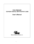
DESCRIPTION
The IOD-96E board was designed for industrial applications and should be installed in a
long slot of an IBM PC/XT/AT or compatible computer. The board contains four
Programmable Peripheral Interface chips type 8255-5 (PPI) to provide computer interface
to 96 digital I/O lines. Each PPI provides three 8-bit ports A, B, and C. Each 8-bit port can
be configured to function as either inputs or output latches. Port C can also be configured
as four inputs and four output latches.
Two I/O lines of each port can be used for interfacing User Interrupts to the computer.
Interrupts are enabled by jumper installation or by a combination of jumper installation and
a digital input line. You can use Interrupts #2 through #7. Interrupts of all ports (one per
port) are OR'ed together.
I/O wiring connections are via 50-pin headers on the board. Five flat I/O cables connect
IOD-96E to termination panels such as ACCES model STA-50. Also, this provides
compatibility with OPTO-22, Gordos, Potter & Brumfield, etc. module mounting racks.
Every second conductor of the flat cables is grounded to minimize the effect of crosstalk
between signals. If needed for external circuits +5VDC power is available on each I/O
connector pin 49. If you use this power, we recommend that you include a 1A fast blow
fuse in your circuits in order to avoid possible damage to the host computer.
2-1
DIGITAL INPUT/OUTPUT CARD
IOD-96E
USER MANUAL
The board occupies sixteen consecutive bytes within the I/O address space. The base
address is selectable via ADDRESS SETUP DIP switches (A5-A9) anywhere within the
hex 000-3FF range. Refer to the OPTION SELECTION Section of this manual for a
detailed description.
Utility software provided with the IOD-96E card is an illustrated setup program. Interactive
displays show locations and proper settings of DIP switches and jumpers to set up board
address, interrupt levels, and interrupt enable..
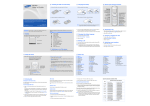
Fig.1 IOD-96E BLOCK DIAGRAM.
(Typical of Four Sections)
Figure 2
2-2
DIGITAL INPUT/OUTPUT CARD
IOD-96E
USER MANUAL
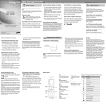
OPTION SELECTION
Refer to the illustrated setup programs on the CD provided with the card when reading
this section of the manual. Also, refer to the OPTION SELECTION MAP below. Base
address selection is covered both by the CD and in section 4 of this manual.
Interrupts are accepted on the I/O connector, pin 9 (port C3). The interrupt signal is
positive true. Interrupts are enabled if I/O connector pin 1 (port C) is held low. Interrupts
are disabled if I/O connector pin 1 (port C7) is held high. User interrupts are directed to
interrupts #2 through #7 by jumpers marked IN2, 3, 4, 5, 6, 7.
The foregoing are the only manual setups necessary to use the IOD-96E. Input/Output
selection is done, via software, by writing to the PPI 8255-5 Control Registers as described
in the PROGRAMMING section of this manual.
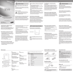
Fig.2 OPTION SELECTION MAP
3-1
DIGITAL INPUT/OUTPUT CARD
IOD-96E
USER MANUAL
ADDRESS SELECTION
The IOD-96E Input/Output Card occupies 16 bytes of I/O space. The card base address
can be selected anywhere within an I/O address range 000-3FF hex. However two
installed options can not share the same address. If in doubt where to assign the base
address of the IOD-96E, refer to the Table below for a list of standard address assignments.
TABLE 1.
Hex Range
000-00F
020-021
040-043
060-063
080-083
0AX
0CX
0EX
100-1FF
200-20F
210-217
220-24F
278-27F
2F0-2F7
2F8-2FF
300-31F
320-32F
378-37F
380-38C**
380-389**
3A0-3A9
3B0-3BF
3C0-3CF
3D0-3DF
3E0-3E7
3F0-3F7
3F8-3FF
Usage
DMA Chip 8237A-5
Interrupt 8259A
Timer 8253-5
PPI 8255A-5
DMA Page Register
NMI Mask Register
Reserved
Reserved
Not Usable
Game Control
Expansion Unit
Reserved
Reserved
Reserved
Asynchronous Comm'n (Secondary)
Prototype Card
Fixed Disk
Printer
SDLC Communications
Binary Synchronous Comm. (Secondary)
Binary Synchronous Comm. (Primary)
IBM Monochrome Display/Printer
Reserved
Color/Graphics
Reserved
Diskette
Asynchronous Comm'n (Primary)
** These options can not be used together - addresses overlap
To set desired board address, refer to the illustrated Board Address setup program on the
CD provided with the card. Type the desired address in hexadecimal code and the graphic
display shows you how to set the ADDRESS SETUP switches. These switches are
marked A4-A9 and form a binary representation of the address in negative-true logic.
Assign '0' to all ADDRESS SETUP switches turned ON, and assign '1' to all ADDRESS
SETUP switches turned OFF.
4-1
DIGITAL INPUT/OUTPUT CARD
IOD-96E
USER MANUAL
The following example illustrates switch selection corresponding to hex 2D0 (or binary 10
1101 xxxx) The "xxxx" represents address lines A3, A2, A1, and A0 used on the card to
select individual registers at the PPI's. See section 5, PROGRAMMING.
HexRepresentation
2
D
Conversion Multipliers
2
1
8
4
2
1
Binary Representation
1
0
1
1
0
1
Setup
OFF
ON
OFF
OFF
ON
OFF
Switch ID
A9
A8
A7
A6
A5
A4
CAUTION
Review the address selection reference table carefully before
selecting the card address. If the addresses of two installed
functions overlap you will experience unpredictable computer
behavior.
4-2
DIGITAL INPUT/OUTPUT CARD
IOD-96E
USER MANUAL
SOFTWARE
ACCES supplies several programs to support the IOD-96E Digital I/O card and, also, to
help you develop your applications software. These programs are on a CD that comes
with your card and consist of a Setup program and three sample programs. (Other
software included on the CD is described in the Installation section of this manual.) The
sample programs are in forms suitable for use with QuickBASIC, C, and Pascal. The
programs as follows:
*
FINDBASE. . Locates available I/O addresses
*
SETUP . . . Board Setup Program
FINDBASE
This DOS program provides means for you to select an I/O bus address that will not
conflict with other installed computer resources. When you select a base address, the
monitor displays a picture of the address-selection DIP switch that shows the correct
positions of the switches to select the base address you want.
SETUP
This menu-driven program provides a picture of the card on the computer monitor. You
make simple keystrokes to select the function you want and the picture changes to show
how the jumpers or switches should be placed to effect your choices.
These programs do not program the card. You must manually place the jumpers and
switches.
5-1
DIGITAL INPUT/OUTPUT CARD
IOD-96E
USER MANUAL
PROGRAMMING
,
The IOD-96E is an I/O mapped device that is easily configured from any language and any
language can easily perform digital I/O through the card's ports. This is especially true if
the form of the data is byte or word wide. All references to the I/O ports would be in
absolute port addressing. However, a table could be used to convert the byte or word data
ports to a logical reference.
DEVELOPING YOUR OWN APPLICATION SOFTWARE
If you wish to gain a better understanding of the programs listed in the previous section,
then the information in the following paragraphs will be of interest to you. Follow the
8255-5 Specification in APPENDIX A to program the PPI's on the IOD-96E Digital
Input/Output Card.
A total of 16 address locations are used by the IOD-96E for addressing the PPI's; four for
each PPI. The PPI's are addressed using address bits A3 through A0 (See Address
Selection, section 4 of this manual.) as follows:
CONTROL REGISTER ADDRESS SELECTION TABLE
Address
Base Address
Base Address +1
Base Address +2
Base Address +3
Base Address +4
Base Address +5
Base Address +6
Base Address +7
Base Address +8
Base Address +9
Base Address +A
Base Address +B
Base Address +C
Base Address +D
Base Address +E
Base Address +F
Port Assignment
Operation
PA Port 0
PB Port 0
PC Port 0
Control Port 0
PA Port 1
PB Port 1
PC Port 1
Control Port 1
PA Port 2
PB Port 2
PC Port 2
Control Port 2
PA Port 3
PB Port 3
PC Port 3
Control Port 3
Read/Write
Read/Write
Read/Write
Write Only
Read/Write
Read/Write
Read/Write
Write Only
Read/Write
Read/Write
Read/Write
Write Only
Read/Write
Read/Write
Read/Write
Write Only
The IOD-96E uses four 8255-5 PPI's to provide a total of 96 bits input/output capability.
The card is designed to use each of these PPI's in mode 0 wherein:
a.There are two 8-bit ports (A and B) and two 4-bit ports (C Hi and C Lo).
b. Any port can be configured as an input or an output.
c. Outputs are latched.
6-1
DIGITAL INPUT/OUTPUT CARD
IOD-96E
USER MANUAL
d. Inputs are not latched.
Each PPI contains a control register. This Write-only, 8-bit register is used to set the
mode and direction of the ports. At Power-Up or Reset, all I/O lines are set as inputs.
Each PPI should be configured during initialization by writing to the control registers even
if the ports are going to be used as inputs. Output buffers are automatically set by
hardware logic according to the control register. Control registers are located at base
addresses +03, +07, +0B, and +0F. Bit assignments in each of these control registers are
as follows:
CONTROL REGISTER BIT ASSIGNMENTS
Bit
Assignment
Function
D0
D1
D2
D3
D4
D5,D6
Port C Lo (C0-C3)
Port B
Mode Selection
Port C Hi (C4-C7)
Port A
Mode Selection
D7
Mode Set Flag
1 = Input, 0 = Output
1 = Input, 0 = Output
1 = Mode 1, 0 = Mode 0
1 = Input, 0 = Output
1 = Input, 0 = Output
01 = Mode 1, 00 = Mode 0
1X = Mode 2
1 = Active
NOTE: Contact ACCES for directions if you wish to operate this card in mode 1 or
mode 2.
(Continued on next page)
6-2
DIGITAL INPUT/OUTPUT CARD
IOD-96E
USER MANUAL
PROGRAMMING EXAMPLE
The following programming example is provided as a guide to assist you in developing
your working software. In this example, the card base address is 2D0 hex and I/O lines
of Port 0 are to be setup as follows:
port A = Input
port B = Output
port C hi = Input
port C lo = Output
Configure bits of the Control Register as:
D7 D6
D5
D4
D3
D2
D1
D0
1 0
0
1
1
0
0
0
|
|
|
|
|
|
|
|
|
|
|
|
|
|
| Port C Lo = output
|
l
|
|
|
|
|
|
|
|
|
|
l
l__________ Port B = output
|
|
|
|
l
|
|
|
|
|
|
|_________________ Mode 0
|
|
|
|
|
|
|
|
|
|_______________________ Port C Hi = input
|
|
|
|
|
|
|
|______________________________ Port A = input
|
|
|
|
|
|_____________________________________ Mode 0
|
|
|
|____________________________________________Mode 0
|
|_______________________________________________ Active Mode Set
This corresponds to 98 hex. If the card base address is 2D0 hex, use the C command to
write to the control register as follows:
Base=0x2D0;
outportb(Base+3,0x98);
To read the inputs at Port A and the upper nybble of Port C, use the C command:
x=inportb(Base);
//Read Port A
y=inportb(Base+2)/16;
//Read Port C Hi
To set outputs high ("1") at Port B and the lower nybble of Port C:
outportb(Base+1,0xFF);
//Turn on all Port B bits
outportb(Base+2,0xF);
//Turn on all bits of Port C Lo
6-3
DIGITAL INPUT/OUTPUT CARD
IOD-96E
USER MANUAL
SAMPLE PROGRAMS
The following sample programs are in TURBO-C and TURBO-PASCAL languages. They
cover a security system that allows you to monitor the status of 16 switches and to
automatically trigger four alarms that can be used to turn on lights, activate a siren, or
send a signal to a silent alarm. The alarm system in this demonstration has four arming
stations which toggle the alarm on or off. These programs are also provided on the CD
that ACCES supplied with your IOD card.
TURBO-PASCAL PROGRAM
CONST BASEADDR = $300;
CONST ON
= 1;
CONST OFF
= 0;
{declare base address for IOD card}
{declare some useful constants}
{ "
"
"
"
}
TYPE sensor_array = array[0..15] of integer;
{creates a type of variable used for sensor data}
VAR sensors_at_arm : sensor_array;
{bit-by-bit status of sensors when alarm is activated. Used to notify user of open windows, etc}
VAR sensors_now : sensor_now;
{bit-by-bit status of sensors at current time. When}
{compared against sensors_at_arm, indicates}
{break-in if there is a change.}
VAR arming_stations : integer;
{variables representing all four arming stations. If}
VAR old_arming_stations: integer;
{value changes toggle alarm on/off}
VAR hour, min., sec., hun. : word;
{variables used to retrieve time}
VAR key : char;
{useful temporary variable}
VAR i : integer;
{useful temporary variable, used in loops}
VAR j : integer;
{ "
"
"
"
"
" }
procedure initialize_board;
begin
port[BASEADDR+3] :=$93;
{this procedure sets MODE 0 as active and sets}
{Port A, B, and C LO as input and Port C HI as}
{output}
{port[X] is Pascal's method of accessing the port}
{memory. This code sets the port memory at}
{address 303 hex, the control register, and to 93}
{hex because the bit pattern to set the desired}
{mode and port designations is} 10010011 which}
{equals 93 hex}
end; {procedure initialize_board}
6-4
DIGITAL INPUT/OUTPUT CARD
IOD-96E
USER MANUAL
procedure read_sensors(VAR ary:sensor_ary);
VAR tempA : byte;
{this procedure fetches data from Ports A and B}
VAR tempB: byte;
{and returns a binary representation of each sensor}
begin
tempA := port[BASEADDR];
{this procedure loads tempA and tempB with corre
tempB:=port[BASEADDR+1]:
{sponding inputs
from the IOD card}
for i:= 0 to 7 do begin
if ((tempA shr i) AND ON) > 0 then {this tests to see if bit #i is ON and sets the}
ary[i]:=ON
{corresponding array element to ON if it is}
else
{.. else, the array element is set to OFF}
ary[i]:=OFF
end;
for i:=0 to 7 do begin
if ((tempB shr i) AND ON) > 0 then
ary[i+8]:=ON
{n order to get Port B into array, elements 8}
else
{ thru 15, we add 8 to the bit numbers in the}
ary[i+8]:=OFF;
{assignment}
end;
end;{procedure read_sensors}
function get_status:integer;
var temp:integer;
begin
temp:=port[BASEADDR+2];
get_status:=temp AND $0F;
end; {function get_arming_status
procedure ALARM
var temp:longint;
begin
sound(2000);
{this sets status to the lower nybble of Port}
{C;the half defined by Initialize to be input for}
{four arming switches}
{this starts the computer's speaker which}
{acts as siren for the alarm}
temp:=0
port[BASEADDR+2]:=$F;
{this sets Port C's lower nybble bits to ON}
repeat
arming_stations:=get_status
{this activates four alarm outputs and then}
if arming_stations <> old_arming_stations then
{toggles Port C hi's LSB which}
temp:=2000000000; {disarmed}
{might be used with external siren}
port[BASEADDR+2]:=port[BASEADDR+2] XOR $10;
temp:=temp+1;
until temp>=2000000000;
nosound;
end; {procedure ALARM}
6-5
DIGITAL INPUT/OUTPUT CARD
IOD-96E
USER MANUAL
begin
initialize_board;
clrscr;
gotoxy(5,5);
writeln('This is the IOD card demonstration program. This ');
writeln('program will simulate an alarm system program for ');
writeln('sixteen sensors and four arming stations, along with');
writeln('four separate alarm outputs which could be routed to');
writeln('a siren, lights, silent alarm,etc');
writeln;
writeln('THIS PROGRAM IS INTENDED FOR DEMONSTRATION PURPOSES,');
writeln('ONLY AND IS NOT MEANT TO BE USED AS AN ACTUAL ALARM ');
writeln('SYSTEM.');
writeln;writeln;
writeln('Press any key to begin program.');
key:readkey;
old_arming_stations:=get_status;
{this loads the status of the arming sitches}
repeat
{at the time the program is first activated.}
clrscr;
{A change in status indicates arming)
read_sensors(sensors_now);
{this reads the current status of the
sensors}
for i=0 to 15 do begin
{which is then displayed to indicate open}
if sensors_now[i]=OFF then
{windows, etc.}
writeln('Sensor #',i,'is open');
end;
writeln;
writeln('Press ESC to re-scan, RETURN to begin alarm scanning.');
key:=readkey;
until key=#13;
{the repeat/until loop gives the user an oppor-}
{tunity to shut open windows or doors, and then}
{re-scan the sensors}
clrscr;
WHILE TRUE do begin
{this WHILEis used to form an infinite loop}
Writeln('Waiting to be armed, or press any key to halt program.');
repeat
arming_stations:=get_status;
if key pressed then halt(1);
{this repeat/until-loop continues until arming}
{station status changes indicating arming or }
{until a key is pressed indicating program}
{termination}
6-6
DIGITAL INPUT/OUTPUT CARD
IOD-96E
USER MANUAL
until arming stations <> old arming stations;
sound(900);
{short tone indicating that alarm has been armed}
delay(300);
{ "
"
"
"
"
" " " }
nosound;
{ "
"
"
"
"
" " "}
writeln('Alarm system will activate in 15 seconds');
read_sensors(sensors_at_arm);
old_arming_stations : get_status;
gettime(hour,min,sec,hun);
{this code reads the system clock for the current}
i:=sec+15;
{time which is used to delay for 15 seconds}
if i > 60 then i :=i-60;
repeat
gettime(hour,min,sec,hun);
until sec = i;
{end of delay loop}
writeln;
writeln('ALARM SYSTEM ACTIVE AND ARMED');
sound(900);
{short tone indicating that alarm is fully activated}
delay(300);
no sound;
j:=0
{the following code compares current status of sen{sors against status when armed to determine if}
{break-in has occurred..any change indicates}
{break-in}
repeat
read_sensors(sensors_now);
for i:= 1 to 16 do begin
if sensors_now[i-1] <> sensors_at_arm[i-1]then
j:=1;
end;{for}
arming_stations: get_status;
if arming_stations <> old_arming_stations then
j:= -i;
{flag used to signal that alarm is de-activated}
until j <> 0;
if j = -1 then begin
{j was set to -1 in the above loop, then alarm is}
{de-activated}
gettime(hour,min,sec,hun);
writeln('Alarm deactivated at ', hour,':',min,':',sec);
sound(900);
{the following code chirps the speaker to indicate}
{disarming}
delay(100);
no sound;
delay(50);
sound(900);
6-7
DIGITAL INPUT/OUTPUT CARD
IOD-96E
USER MANUAL
delay(100);
nosound;
end
{end of disarming routine}
else {if alarm}begin
writeln('Sensor #', j,' has been activated!!');
gettime(hour,min,sec,hun);
writeln('The time of alarm is ',hour,':',min,':',sec);
ALARM;
end;
{else}
end;
{WHILE this "end" sends the program back to wait}
{to be re-armed}
end.
TURBO-C PROGRAM
#define BASEADDR 0x300
#define ON
1
#define OFF
0
#include "stdio.h"
#include "conio.h"
#include "time.h"
#include "dos.h"
int sensors_at_arm[15];
int sensors_now[15];
int arming_stations;
int_old_arming_stations;
char key;
int i;
int j;
initialize(){
outportb(BASEADDR+3,0x93);
/*declare base address for IOD card*/
/*create useful constant*/
/* " "
" */
/*bit-by-bit status of sensors at current time. When*/
/*compared against status of sensors at arm,*/
/*indicates break-in if there is a change.*/
/*variables representing all four arming stations.If*/
/*the value changes,toggle alarm ON/OFF.*/
/*useful temporary variable*/
/*useful temporary variable used in loops*/
/*useful temporary variable*/
/*outportb(addr,byte) is C's method of accessing
/* port memory. This procedure sets Port A, B,*/
/*and C LO as inputs and Port C hi as outputs */
/*Address 303 hex is the control register. The bit*/
/*pattern needed to set the desired mode and */
/*port designation is 10010011 = 93 Hex*/
} /*procedure initialize*/
read_sensors(int *ary){
6-8
DIGITAL INPUT/OUTPUT CARD
unsigned char tempA;
unsigned char tempB;
tempA = inportb(BASEADDR);
tempB = inportb(BASEADDR+1);
for(i-0;i<8;i++){
if((tempA>> i) & ON){
*ary++=ON;}
else{
*ary++=OFF;}
}
for(i=0;i<8;i++){
if((tempB>> i) & ON){
*ary++=ON; }
else
*ary++=OFF;}
}
} /*procedure read_sensors*/
get_status(){
int temp;
temp=inportb(BASEADDR+2);
return temp & 0x0F;
} /*function get_arming_status*/
ALARM(){
long int temp=0;
sound(2000);
outportb(BASEADDR+@,0xF0);
IOD-96E
USER MANUAL
/*this determines if bit #i is on and sets the corres-*/
/*ponding array element to ON if it is. If not, sets */
/*the array element to OFF */
/*this sets status to the lower half of Port C, the */
/*the half defined in Initialize to be input, for four */
/*four arming switches*/
/*this starts the computer's speaker*/
/*this sets Port C upper nybble bits to ON (1111 */
/*binary = F hex).*/
do{
arming_stations=get_status();
/*this activates 4 alarm outputs and then togles */
if(arming_stations !=old_arming_stations) /*Port C Hi LSB which might be used */
temp=2000000000; /*dis-armed*/
/*with an external speaker*/
outportb(BASEADDR+2,inportb(BASEADDR+2)^0x10);
}while(temp++ !=2000000000);
nosound();
}/*procedure ALARM*/
-=-=-=-=-=-=-=-=-=-=-=-=-=-=-=-=-=-=-=-=-=-=-=-=-=-=-=-=-=-=-=-=-=--=-=-=-=-=-=-=-=-=-=main()
{
time_t start;
initialize();
clscr();
goto(5,5);
6-9
DIGITAL INPUT/OUTPUT CARD
IOD-96E
USER MANUAL
printf("This IOD-card demonstration program simulates an alarm\n");
printf("system program for 16 sensors, four arming stations and\n");
printf("four separate alarm outputs which could be routed to a\n");
printf("siren, lights, silent alarm, etc.\n");
printf("\n");
printf("THIS PROGRAM IS FOR DEMONSTRATION PURPOSES ONLY, AND IS\n");
printf("NOT MEANT TO BE USED AS AN ACTUAL ALARM SYSTEM.\n");
printf("\n");printf("n");
printf("Press any key to begin program.\n");
key=getch();
old_arming_stations=get_status();
do{
clrscr();
read_sensors(sensors_now);
for(i=0;i<=15;i++){
if (!sensors_now[i]) printf("Sensor #%d %s\n,i,"is open");
}
printf("\n");
printf("Press ESC to re-scan, RETURN to begin alarm scanning.");
key=getch();
}while(key!=13);
clrscr();
for(;;)
{/*this creates an infinite loop*/
printf("Waiting to be armed. Press any key to halt program.\n");
do{
arming_stations=get_status();
if(kbhit()) abort(0);
}while(arming_stations== old_arming_stations);
sound(1000);
delay(300);
nosound();
printf("Alarm system will activate in 15 seconds");
read_sensors(sensors_at_arm);
old_arming_stations=get_status();
start=time(NULL);
do{
}while(difftime(time(NULL),start) !=15);
printf("\n");
printf("ALARM SYSTEM ACTIVE AND ARMED\n\n");
sound(900);
delay(300);
nosound();
j=0;
do{
6-10
DIGITAL INPUT/OUTPUT CARD
IOD-96E
USER MANUAL
read_sensors(sensors_now);
for(i=1;i<=16;i++){
if(sensors_now[i-1] !=sensors_at_arm[i-1])
j=i;
}
/*for*/
arming_stations = get_status();
if (arming_stations != old_arming_stations)
j=-1
/*flag used to signal alarm is de-activated*/
while(!j);
if(j == -1){
start=time(NULL);
printf("Alarm deactivated at %s,(asctime(gmtime(&start))));
sound(900); delay(300);
nosound(); delay(50);
sound(900); delay(100);
nosound();
}
else {
printf("Sensor #%d has been activated!!\n\n",j);
start=time(NULL);
printf("The time of alarm is %s", asctime(gmtime( &start)));
old_arming_stations=get_status();
ALARM();
}
/*else*/
}
/* for(;;) this "end" used to send program
back*/
/*to await re-arm*/
}
6-11
DIGITAL INPUT/OUTPUT CARD
IOD-96E
USER MANUAL
CONNECTOR PIN ASSIGNMENTS
Four 50-pin headers are provided on the IOD-96E card; one for each group of 24 I/O lines.
The mating connector is an AMP type 1-746285-0 or equivalent. Connector pin
assignments are listed below. Notice that every second line is grounded to minimize
crosstalk between signals.
Assignment
Pin
Assignment
Pin
Port C Hi PC7*
Port C hi PC6
Port C Hi PC5
Port C Hi PC4
1
3
5
7
Ground
"
"
"
2
4
6
8
Port C Lo PC3**
Port C Lo PC2
Port C Lo PC1
Port C Lo PC0
9
11
13
15
Ground
"
"
"
10
12
14
16
Port B
Port B
Port B
Port B
Port B
Port B
Port B
Port B
PB7
PB6
PB5
PB4
PB3
PB2
PB1
PB0
17
19
21
23
25
27
29
31
Ground
"
"
"
"
"
"
"
18
20
22
24
26
28
30
32
Port A
Port A
Port A
Port A
Port A
Port A
Port A
Port A
PA7
PA6
PA5
PA4
PA3
PA2
PA1
PA0
33
35
37
39
41
43
45
47
Ground
"
"
"
"
"
"
"
34
36
38
40
42
44
46
48
49
Ground
50
+5 VDC
Notes:
* This line is an I/O port and also an Interrupt Enable.
** This line is an I/O port and also a User Interrupt.
7-1
DIGITAL INPUT/OUTPUT CARD
IOD-96E
USER MANUAL
SPECIFICATION
Features
96 Input/Output lines
Pull-ups on I/O lines for CMOS and contact-closure compatibility.
Compatibility with module mounting racks
Digital Inputs
Logic High: 2.0 to 5.0 VDC.
Logic Low: -0.5 to +0.8 VDC.
Input Load (Hi): +10 uA.
Input Load (Lo): -10 uA.
Digital Outputs
Logic High: 2.5 VDC min., source 200 uA
Logic Low: 0.5 VDC max., sink 1.7 mA
Power Output: +5 VDC from computer bus (ext. 1A fast blow fuse recommended).
Power Requirements: +5 VDC at 400 mA typical.
Size: 7" long (178 mm).
Environmental
Operating Temperature Range: 0 degr. to 60 degr.C.
Storage Temperature Range: -50 degr. to +120 degr.C.
Humidity: 0 to 90% RH, non-condensing.
8-2
DIGITAL INPUT/OUTPUT CARD
IOD-96E
USER MANUAL
WARRANTY
Prior to shipment, ACCES equipment is thoroughly inspected and tested to applicable
specifications. However, should equipment failure occur, ACCES assures its customers that
prompt service and support will be available. All equipment originally manufactured by ACCES
which is found to be defective will be repaired or replaced subject to the following considerations.
TERMS AND CONDITIONS
If a unit is suspected of failure, contact ACCES' Customer Service department. Be prepared to
give the unit model number, serial number, and a description of the failure symptom(s). We may
suggest some simple tests to confirm the failure. We will assign a Return Material Authorization
(RMA) number which must appear on the outer label of the return package. All units/components
should be properly packed for handling and returned with freight prepaid to the ACCES
designated Service Center, and will be returned to the customer's/user's site freight prepaid and
invoiced.
COVERAGE
First Three Years: Returned unit/part will be repaired and/or replaced at ACCES option with no
charge for labor or parts not excluded by warranty. Warranty commences with equipment
shipment.
Following Years: Throughout your equipment's lifetime, ACCES stands ready to provide on-site
or in-plant service at reasonable rates similar to those of other manufacturers in the industry.
EQUIPMENT NOT MANUFACTURED BY ACCES
Equipment provided but not manufactured by ACCES is warranted and will be repaired according
to the terms and conditions of the respective equipment manufacturer's warranty.
GENERAL
Under this Warranty, liability of ACCES is limited to replacing, repairing or issuing credit (at
ACCES discretion) for any products which are proved to be defective during the warranty period.
In no case is ACCES liable for consequential or special damage arriving from use or misuse of
our product. The customer is responsible for all charges caused by modifications or additions
to ACCES equipment not approved in writing by ACCES or, if in ACCES opinion the equipment
has been subjected to abnormal use. "Abnormal use" for purposes of this warranty is defined as
any use to which the equipment is exposed other than that use specified or intended as evidenced by purchase or sales representation. Other than the above, no other warranty, expressed
or implied, shall apply to any and all such equipment furnished or sold by ACCES.
9-1
DIGITAL INPUT/OUTPUT CARD
IOD-96E
USER MANUAL
APPENDIX A
PPI DATA SHEETS
The data sheets in this Appendix are provided to help your understanding of the 8255-5
PPI which is manufactured by several companies. These data sheets are reprinted with
permission of Mitsubishi Electric Corporation. (Copyright 1987).
The information, diagrams, and all other data included are believed to be correct and
reliable. However, no responsibility is assumed by ACCES or Mitsubishi Electric Corp for
their use, nor for any infringements of patents or other rights belonging to other parties
which may result from their use. Values shown on these data sheets are subject to change
for product improvement.
A-2