1
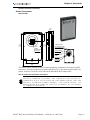
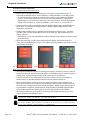
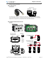
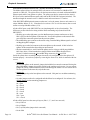
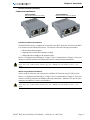
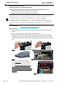
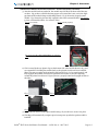
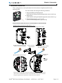
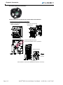
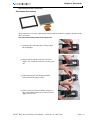
Accessories
Chapter
6
Chapter 6 – Accessories
Optional Accessories���������������������������������������������������������������������������������������������� 6–2
Finger Guards���������������������������������������������������������������������������������������������������������������� 6–2
Remote Touchscreen���������������������������������������������������������������������������������������������������� 6–3
RJ45 to RJ12 Adapter�������������������������������������������������������������������������������������������������� 6–5
Serial Modbus Communication Splitter���������������������������������������������������������������������� 6–5
Communication Modules �������������������������������������������������������������������������������������������� 6–7
Replacement/Spare Parts����������������������������������������������������������������������������������� 6–10
Replacement Cooling Fans ��������������������������������������������������������������������������������������� 6–11
Replacement Touchscreen����������������������������������������������������������������������������������������� 6–13
Stellar® SR55 Series Soft Starter User Manual – 1st Ed. Rev.A – 08/17/2015
Page 6–1
Chapter 6: Accessories
Optional Accessories
SR55 Optional Accessories
Part Number
Description
EtherNet/IP communication module, optional, for Stellar SR55 series soft starters, dual
RJ45 communication ports, complete EtherNet/IP adapter, TCP/IP socket interface,
SR55-CM-ENETIP
CIP parameter object support, explicit and implicit messaging (2 input words, 2 output
words), transformer isolated Ethernet interface, 10/100 Mbps full duplex.
Modbus TCP communication module, optional, for Stellar SR55 series soft starters, dual
RJ45 communication ports, complete Modbus TCP server, up to 256 bytes of I/O data
SR55-CM-MODTCP
in each direction, transformer isolated interface, 100 Mbps full duplex, TCP/IP socket
interface, capable of supporting 4 simultaneous (master) connections.
Finger guards, optional, for size 1 Stellar SR55 series soft starter power terminals.
SR55-FG-1
Provides IP20 protection rating. Package of 2.
Finger guards, optional, for size 2 Stellar SR55 series soft starter power terminals,
SR55-FG-2
Provides IP20 protection rating. Package of 2.
Touchscreen, optional remote, for Stellar SR55 series soft starters. Used to remotely
monitor, configure, and control SR55 series units without opening enclosures. Rated for
SR55-KPD-REM
IP55 enclosures, no external power wiring required. Includes 3m (9.8 ft.) Cat5e cable
and SR55-RJ45-RJ12 adapter.
Serial Modbus communication splitter, optional, for Stellar SR55 series soft starters.
Used for creating a Modbus network with multiple SR55 series soft starters. Uses 3
SR55-SPLT
serial RJ45 connectors for upstream/downstream connectivity and for connection to the
starter. Includes 3m (9.8 ft.) Cat5e cable and SR55-RJ45-RJ12 adapter.
RJ45 female to RJ12 male adapter, optional, for Stellar SR55 series soft starters.
SR55-RJ45-RJ12
For SR555
Models
all
all
-017 thru
-096
-124 thru
-180
all
all
all
Finger Guards
SR55-FG-1
SR55-FG-2
Install these optional finger guards on the power-circuit line and load side power terminals to
provide IP20 protection for soft starter sizes SR55-180 and below (frame sizes 1 and 2).
The addition of optional finger guards to size 1 and size 2 SR55
soft starters adds approximately 14mm [0.5in] to the vertical
dimension, but does NOT change the clearance distance.
Page 6–2
Stellar® SR55 Series Soft Starter User Manual – 1st Ed. Rev.A – 08/17/2015
Chapter 6: Accessories
Optional Accessories (continued)
Remote Touchscreen
SR55-KPD-REM
Ø1.69
[Ø43.0]
Diameter hole
cut in panel
5.30
[134.0]
4.80
[123.0]
1.36
[34.5]
0.90
[23.5]
4x Mounting Holes
No.6 self tapping screws
or M3.5 Machine screws
Neoprene Gasket
RJ45 Socket
(for connecting to
starter)
Reset Switch
2.50
[63.0]
3.70
[94.0]
USB Socket
(for firmware
updates only)
The optional remote touchscreen allows remote monitoring, configuration, and control of SR55
soft starters. Since the touchscreen is a master RS-485 device, it can control multiple SR55 soft
starters. Includes a 3m (9.8ft) Cat5e cable and an SR55-RJ45-RJ12 adapter cable.
How to connect and use remote touchscreen
The SR55-REM-KPD Remote Keypad is a Modbus master. If the Remote
Keypad is connected to an SR55, that starter will not be able to
communicate with a PLC or other 3rd party Modbus master (only one
master is allowed on a Modbus network). For similar reasons, the
Remote Keypad also cannot be used with the Modbus TCP or Ethernet
IP communication modules.
Stellar® SR55 Series Soft Starter User Manual – 1st Ed. Rev.A – 08/17/2015
Page 6–3
Chapter 6: Accessories
Optional Accessories (continued)
How to connect the remote touchscreen
• Ensure starter’s Modbus Network Settings are: Even parity and 19200 baud rate. If
connecting to multiple starters, set the Address to a unique number for each SR55 starter.
• If remote touchscreen start/stop control is desired, set the Control Method to Modbus
Control. If the remote touchscreen will only be used for monitoring or configuration
(digital input or local touchscreen start/stop control will be used), select the appropriate
setting (Local Touchscreen, User Programmable, 2-wire control, or 3-wire control).
• Connect remote touchscreen using the SR55-RJ45-RJ12 adapter and a standard Ethernet
patch cable. If connecting to multiple starters, a Modbus splitter (SR55-SPLT) will be
required for each starter.
• On the remote touchscreen go to Modbus Network Settings as shown in Fig 1. and select
Scan Bus. This will show all the SR55 starters on the bus Fig 2. Select which starter you
wish to connect to.
• Alternatively you can select the Address number and then select Connect to connect to that
particular starter.
• The status screen Fig 3 on the remote touchscreen will display the current starter it is
connected to by displaying the starter’s node address and serial number (EX: address 01 and
serial number A0167805)
Fig 1
Fig 2
Fig 3
How to use the remote touchscreen
• The remote touchscreen’s control for starting and stopping overrides the starter’s onboard
touchscreen when the starter’s Control Method is set to Modbus Control. Menu navigation,
configuration, and monitoring are still possible on the starter’s touchscreen.
• Press the starter icon box on the Status screen of the remote touchscreen to change to
another starter if controlling multiple starters from one remote touchscreen.
• When using the remote touchscreen for start/stop control the remote touchscreen has
full control, configuration, and monitoring capabilities, while the local touchscreen on the
starter only has configuration and monitoring capabilities. Digital outputs always function
as programmed, regardless of Control Mode. Digital inputs are disabled during Modbus
Control and Keypad Control Modes, but are active during all other Control Modes.
• The remote touchscreen can be used for monitoring and configuration during any other
control method besides Modbus Control.
The remote touchscreen cannot be used with a communication module
installed (SR55-CM-ENETIP or SR55-CM-MODTCP).
The remote touchscreen is a Modbus RTU master device. A PLC, HMI,
or other Modbus Master device cannot be used on the same network
while the remote touchscreen is connected.
Page 6–4
Stellar® SR55 Series Soft Starter User Manual – 1st Ed. Rev.A – 08/17/2015
Chapter 6: Accessories
Optional Accessories (continued)
RJ45 to RJ12 Adapter
SR55-RJ45-RJ12
SR55-RJ45-RJ12
Splitter End
Starter End
RJ45 Socket
RJ12 Plug
87654321
123456
This adapter allows connection of the Remote Touchscreen, Modbus Splitter, or other Modbus
master to the SR55 soft starter. The adapter plugs directly into the RJ12 port on top of the SR55,
and provides a receptacle for a communication cable with an RJ45 connector.
Serial Modbus Communication Splitter
SR55-SPLT
With front cover on
(4) screws to remove
front cover to access
configration jumpers
With front cover off
Pin-out same
for all 3 ports:
RJ45 ports
SR55-SPLT
8
1
1 = n/c
2 = n/c
3 = n/c
4 = TXD1-B
5 = TXD0-A
6 = n/c
7 = 24VDC
8 = GND
Single SR55 RS-485 network
(SR55-SPLT optional)
SR55-xxx
Multiple SR55 RS-485 network
(one SR55-SPLT per starter
recommended)
SR55-SPLT
SR55-xxx
SR55-xxx
SR55-xxx
Dimensions = in [mm]
Stellar® SR55 Series Soft Starter User Manual – 1st Ed. Rev.A – 08/17/2015
Page 6–5
Chapter 6: Accessories
Serial Modbus Communication Splitter – Optional Accessories (continued)
The Modus splitter allows for multiple SR55 soft starters to be connected to a Modbus RTU
network over RS-485. The splitter allows for the interconnections to be made with standard RJ45
Ethernet patch cables from splitter to splitter. The splitter can then be connected to the starter’s
RJ12 port with a standard Ethernet patch cable and an SR55-RJ45-RJ12 adapter (included). The
maximum length the network can be is 4000 feet total and a maximum of 31 starters.
If the SR55-KPD-REM optional remote touchscreen is to be the master, then set each starter to a
unique Modbus address (1-31). If another device such as a PLC is to be the master, then set each
starter to a unique Modbus address (2-31).
All three RJ45 ports on the SR55-SPLT are not interchangeable as far as functionality. The
differences are described below along with the BAG terminating strip (located inside the
SR55-SPLT).
• The RJ45 port on the right must go to the Modbus master (remote touchscreen or PLC).
This is only for the first splitter on the network. For all other splitters on the network this
port will be the connection point from the previous splitter.
• The middle RJ45 port connects to the starter using a standard RJ45 Ethernet patch cord and
an SR55-RJ45-RJ12 adapter.
• The RJ45 port on the left connects to the next splitter on the network. If this is the last
splitter on the network then leave this port unconnected.
• The three terminals B, A, and G inside the splitter are for wiring to a third party Modbus
RTU slave device. These terminals are simply TDX00-A and TDX01-B signal lines +
Ground. Use BAG term strip or the middle RJ45 connector; do not use both.
Inside the splitter there are multiple jumpers that need to be configured before the splitter will
function properly. Access these jumpers by removing the front cover, which is attached with four
screws.
• Jumper S6
For the first splitter on the network, jumper S6 inside the box must be connected if using the
SR55-KPD-REM. Jumper S6 provides 24VDC to the touchscreen for power. Do not connect
jumper S6 if using a different master as this could damage the master. Do not connect S6 for
all other splitters on the network, only the first one.
• Jumper S9
Connect jumper S9 on the last splitter on the network. This puts in a 120 Ohm terminating
resistor.
• No other jumper needs to be configured and should not be reconfigured. For reference, the
default settings for the remaining jumpers are:
S1 = open
S2 = open
S3 = closed
S4 = closed
S5 = closed
S7 = closed
S8 = open
S10 = open
S11 = closed
All three RJ45 ports have the same pin layout. (Pins 1, 2, 3, and 6 are not used.)
• Pin 4: TXD1-A
• Pin 5: TXD0B
• Pin 7: 24VDC (when jumper S6 is connected)
• Pin 8: GND
Page 6–6
Stellar® SR55 Series Soft Starter User Manual – 1st Ed. Rev.A – 08/17/2015
Chapter 6: Accessories
Optional Accessories (continued)
Communication Modules
SR55-CM-ENETIP
EtherNet/IP Communication Module
SR55-CM-MODTCP
Modbus TCP Communication Module
EtherNet/IP Communication Module
The EtherNet/IP interface is intended to be installed in the SR55 option slot, and allows the SR55
to be connected to an EtherNet/IP network. The interface offers the following functionality:
• CIP Parameter Object Support
• 2 Input Words from the network master to SR55
• 2 Output Words from SR55 to the network master
Refer to “Configuration and Parameters” Chapter 3 and “Communications” Chapter 5 of this user
manual for detailed parameter and EtherNet/IP network communications information.
Refer to the installation instructions in the following section. Great
care must be taken when inserting the communication module into the
SR55.
Modbus TCP Communication Module
Allows an SR55 soft starter to be connected to a Modbus TCP network using TCP/IP protocol.
Refer to “Configuration and Parameters” Chapter 3 and “Communications” Chapter 5 of this user
manual for detailed parameter and Modbus addressing information. (Modbus TCP uses the same
parameters and addresses as does serial Modbus.).
Refer to the installation instructions in the following section. Great
care must be taken when inserting the communication module into the
SR55.
Stellar® SR55 Series Soft Starter User Manual – 1st Ed. Rev.A – 08/17/2015
Page 6–7
Chapter 6: Accessories
Optional Accessories (continued)
Communication Module Installation Instructions
The following installation instructions apply to both network communication modules:
• EtherNet/IP Communication Module SR55-CM-ENETIP
• Modbus TCP Communication Module SR55-CM-MODTCP
These option modules are specifically designed to be used with the
SR55 range of soft-start products, and are intended for professional
incorporation into complete equipment or systems. Incorrect
installation may present a safety hazard. Before commencing
installation and commissioning, the user should ensure that they are
fully familiar with the SR55 unit, and in particular have read the
important safety information and warnings contained in this SR55 User
Manual.
Instructional Video
https://www.youtube.com/watch?v=ybqj_hwGrm8
Written Instructions
1) Ensure that all power is removed from the SR55 soft starter prior to installing the option
module.
2) Remove the blanking plate from the SR55 option module slot.
3) Carefully slide the communication module into the SR55’s communication slot applying
slight downward force and forward pitch as shown in Fig 1a and Fig 1b in order to ensure
the guide channels on the communication module Fig 2 align to the guide rails in the starter
Fig 3.
Fig.1b
Fig.1a
Fig.3
Fig.2
4) An image of the starter taken apart is
shown for reference of how the module fits
into these guide rails, see fig 4. Please
note: This view cannot be accessed on a
purchased SR55 unit. This picture was
taken on a unit that was taken apart beyond
repair for the purposes of illustrating this
procedure.
Fig.4
Page 6–8
Stellar® SR55 Series Soft Starter User Manual – 1st Ed. Rev.A – 08/17/2015
Chapter 6: Accessories
Communication Module Installation Instructions – Optional Accessories (continued)
5) After the module has been pushed in, the module may feel like it has been seated but may
not have. Fig 5a shows a module that may appear to be seated but is not, notice the slight
gap between the module flange and the SR55 chassis. Fig 5b shows the properly seated
module. Fig 6 shows the pins not fully engaged in this same unseated module. (Fig 6 view
is from a disassembled SR55; for reference only.)
Fig.5b (seated properly)
Fig.5a (not seated)
(Fig 6 view is from a disassembled SR55; for reference
only.)
Fig.6
6) This is caused by the two plastic clips on the bottom side of the module shown in fig 7 and
are responsible for holding the module firmly to the printed circuit board once installed.
These clips can get caught on the printed circuit board (Fig 8). To be seated properly and
fully engaged, the module will need to be pushed down in order to have the clips snap
around the printed circuit board. Figure 9 shows a properly seated and engaged module on
the SR55.
Fig.7
Fig.8
Fig.9
7) Tighten the two screws on the option module using a T9 torx driver to secure it in place.
8) The SR55 will automatically configure upon its next power-up after the option module is
installed.
Stellar® SR55 Series Soft Starter User Manual – 1st Ed. Rev.A – 08/17/2015
Page 6–9
Chapter 6: Accessories
Replacement/Spare Parts
SR55 Replacement Parts *
Part Number
Description
For SR555
Models
SR55-FAN-2 (1)
Cooling fan, replacement, for size 1 Stellar SR55 series soft starters, 60 x 60 x 15 mm
-017 thru -096
SR55-FAN-3 (1)
Cooling fan, replacement, for size 2 Stellar SR55 series soft starters, 80 x 80 x 15 mm
-124
SR55-FAN-6 (1)
Cooling fan, replacement, for size 2 Stellar SR55 series soft starters, 80 x 80 x 20 mm
-156 thru -180
SR55-FAN-7 (1)(2) Cooling fan, replacement, for size 3 Stellar SR55 series soft starters, 120 x 120 x 25 mm
SR55-FAN-8 (3)
-242 thru -361
Cooling fan, replacement, for size 3 Stellar SR55 series soft starters, 171 x 151 x 151 mm -414 thru -477
Touchscreen, replacement, for Stellar SR55 series soft starters
all
SR55-KPD
* These items are exact replacements for the comparable part that is originally installed on the applicable SR55.
(1) All fans (except SR55-FAN-8) come with 3 butt-splice terminals. If replacement terminals are needed, they can be
purchased from a third party distributor. PN: UY2; MFG: 3M.
(2) SR55-FAN-7 also comes with 4 push rivets. If replacement rivets are needed, they can be purchased from a third
party distributor. PN:SR-4070B; MFG: Essentra Components.
(3) SR55-FAN-8 uses 1/8” quick-connect terminals.
Page 6–10
Stellar® SR55 Series Soft Starter User Manual – 1st Ed. Rev.A – 08/17/2015
Chapter 6: Accessories
Replacement Cooling Fans
These cooling fans are exact replacements for the fans that are originally installed on the
applicable SR55.
The fans normally run during the following conditions:
1) During the Ramp and Dwell periods.
(Will continue running if heatsink temperature meets criteria #3)
2) During Stop.
(Will continue running if heatsink temperature meets criteria #3)
3) If heatsink temperature >45°C [113°F].
(Turns off when temperature <39°C [102°F])
Fan Replacement Instructions for soft starters SR55-017 through SR55-361
Fan Replacement Instructions for SR55-FAN-2, -3, -6, -7
1) Unscrew existing fan(s).*
3) Fit blue wires from new fan and
SR55 into connector (included).
6) Position fan(s) and connectors.*
2) Cut wires close to fan(s).
4) Push connector
shut with pliers.
5) Repeat with 2nd pair of blue,
then 2 pairs of red wires.
7) Fix new fan(s)
to SR55.*
Air flow
direction
* Soft starters SR55-242, -302, and -361 have metal fan guards fitted for safety reasons.
These must be removed before the fans can be taken off, and they MUST be refitted
using the supplied push rivets after the new fans have been attached.
Stellar® SR55 Series Soft Starter User Manual – 1st Ed. Rev.A – 08/17/2015
Page 6–11
Chapter 6: Accessories
Replacement/Spare Parts (continued)
Fan Replacement Instructions for soft starters SR55-414 and SR55-477
Fan Replacement Instructions for SR55-FAN-8
1) Remove 4 screws from
lower end molding.
2) Slide lower end molding
off of busbars.
3) Pull wires off of connectors.
4) Fans held with M4 screws in 2 positions.
5) Remove old fan.
Air flow
direction
6) Fit new fan.
7) Reassemble in reverse order. (Orientation of wires is not critical.)
Page 6–12
Stellar® SR55 Series Soft Starter User Manual – 1st Ed. Rev.A – 08/17/2015
Chapter 6: Accessories
Replacement/Spare Parts (continued)
Replacement Touchscreen
These touchscreens are exact replacements for the touchscreens that are originally installed on the
SR55 soft starters.
Touchscreen Replacement/Installation Instructions
1) Carefully remove the outer bevel casing around
the LCD display.
2) Remove the two plastic rivets below the LCD
display. Use a small screwdriver to pry the rivets
out.
3) When removing the LCD display and PCB,
slowly lift from the top left corner.
4) Gently remove the LCD and PCB at an angle, so
they can be lifted from the unit. Take care not to
apply excessive force.
Stellar® SR55 Series Soft Starter User Manual – 1st Ed. Rev.A – 08/17/2015
Page 6–13
Chapter 6: Accessories
Replacement/Spare Parts (continued)
Touchscreen Replacement/Installation Instructions (continued)
5) On the reverse side of the PCB, remove the FFC
cable from the socket (lift gray part from front
edge; do not force.)
6) Place the replacement screen FFC cable in
socket, making sure that it is correctly seated.
Push the gray part down to lock.
7) Once the socket is locked with the FFC cable
firmly connected, gently place the board back in
to the previous position, using the same angled
technique.
8) Place the PCB flat in position.
9) Make sure that the screen is correctly aligned,
and place the outer bevel back on the LCD
display.
10) Once you have placed the outer bevel back
on the LCD display, ensure that the two plastic
rivets below the LCD display are re-installed.
Page 6–14
Stellar® SR55 Series Soft Starter User Manual – 1st Ed. Rev.A – 08/17/2015