1
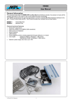
TCF-142-S, TCF-142-M RS-232/422/485 to Fiber Converter User's Manual Second Edition, December 2003 1. Auto Baud Rate Detection TCF-142 incorporates a method for automatically detecting the serial signal’s baud rate by hardware. This is an extremely convenient feature for the user. Even if a device’s baud rate changes, the signal will still be transmitted through the converter without any problem. 2. Features • • • • • • Extend RS-232/422/485 transmission distance: up to 20 km with Single mode—TCF-142-S up to 2 km with Multi-mode—TCF-142-M Convert RS-232/422/485 signal: to ST Single-mode fiber with TCF-142-S to ST Multi-mode fiber with TCF-142-M Plug & Play Compact size Decrease signal interference Protect against electronic degradation/chemical corrosion Support baud rate up to 230.4 Kbps 3. Package Checklist Overview Introduction The TCF-142 series converter is equipped with a multiple interface circuit that can handle RS-232, or RS-422/485 serial interfaces and multimode or single-mode fiber. TCF-142 converters are used to extend serial transmission distance up to 2 km (TCF-142-M multi-mode fiber) or up to 20 km (TCF-142-S single-mode fiber). RS-232 or RS-422/485 interfaces can’t be used to convert to Fiber on the same TCF-142 at the same time. Why convert serial to Fiber? Fiber communication not only extends the communication distance, but also provides many good features as follows: IMMUNE FROM ELECTRICAL INTERFERENCE: Fiber is not affected by electromagnetic interference or radio frequency interference. It provides a clean communication path and is immune to cross-talk. INSULATION: Optical fiber is an insulator; the glass fiber eliminates the need for electric currents for the communication path. SECURITY: Cannot be tapped by conventional electric means and is very difficult to tap onto optically. Furthermore, radio and satellite communication signals can easily be captured for decoding. RELIABILITY & MAINTENANCE: Fiber is immune to adverse temperature and moisture conditions, does not corrode or lose its signal, and is not affected by short circuits, power surges, or static electricity. Reverse Power Protection The Reverse Power Protection feature provides extra protection against accidentally connecting the power cables to the wrong terminal. The converter is designed to automatically detect which power wire is positive and which is negative, and then adjust the power supply accordingly. DIP Switch Selectable Terminator For many products of this type, the termination resistor is set by a jumper located inside the product’s casing, so that the user must open the casing to disable or change the resistor’s strength. MOXA offers a better solution. TCF-142’s terminator is set with a DIP Switch located on the outside of the converter’s casing. • Before installing the Converter, verify that the package contains the following items: Standard Accessory • The RS-232/422/485 to Fiber Converter • This User's Manual • 7-contact terminal block connector x 1 • 3-contact terminal block connector x 1 * Notify your sales representative immediately if any of the above items is missing or damaged. 4. Dimensions and Appearance Note: TCF-142 series are hot swappable. • Wear a grounding device for electrostatic discharge. • Install the media cable for network connection. Fig. 1: TCF-142’s dimensions and appearance 5. Wiring example: Connecting the Power Supply Before using the TCF-142, you need to connect the power supply. To do so, connect the power supply to the power supply terminal block located on the bottom side of TCF-142. Note: TCF-142 uses a DC power supply. Serial Device to PC Fig. 2: Connecting RS-232 device and PC —1— —2— —3— Fiber Communication Connector type Distance Support Cable Fig. 3: Connecting RS-422 or 4-wire RS-485 device and PC Wave length Min.TX Output Fig. 6: LED position figure Fig. 4: Connecting 2-wire RS-485 device and PC 8. Max.TX Output Environment Operating Temperature Storage Temperature Power Input Power Voltage Power Line Protection RS-422/485 circuit diagram VCC 6. Switch Settings U8 There are 3 sets of DIP switches on the top of the TCF-142. TXD0A TXD0B R31 R32 8 7 6 5 10Ω 10Ω VCC DD+ GND 1 2 3 4 R ENR ENT T FRXD EN485T0 Reverse Power Protection Over Current Protection SN75HVD07DR Power Consumption VCC VCC Mechanical Dimensions (WxDxH) R18 10K U7 Fig. 5: DIP Switch position figure Serial Connection RS-232 RS-422 RS-485 4-wire RS-485 2-wire SW1 ON OFF OFF OFF Built-in 120 Ω Terminator Enable Disable SW3 ON OFF 7. LED Fiber Tx Green Fiber Rx Orang e 8 7 6 5 VCC DD+ GND R ENR ENT T 1 2 3 4 FRXD TER_N0 150K R24 150K Material Gross Weight Regulatory Approvals CE FCC EMI EMS R23 120Ω R22 FTXD EN485R0 EN485R1 Free fall 0 - 60°C (32 - 142°F), 5 to 95 % RH -20 – 85°C (-4 - 185°F), 5 to 95 % RH 12 – 48 VDC 1 KV Burst (EFT), EN61000-4-4 1 KV Surge, EN61000-4-5 Protects against V+/V- reversal Protects against 2 signals shorted together: 1.1A TCF-142-M: 70mA at 12 VDC TCF-142-S: 145 mA at 12 VDC 67 x 100 x 22 mm 90 x 100 x 22 mm (including ears) Aluminum (1 mm) TCF-142-S: 140g TCF-142-M: 140g Class B Part 15 sub Class B EN55022 1998, Class B EN61000-4-2 (ESD), Criteria A, Level 2 EN61000-4-3 (RS), Criteria A, Level 2 EN61000-4-4 (EFT), Criteria A, Level 2 EN61000-4-5 (Surge), Criteria A, Level 3 EN61000-4-6 (CS), Criteria A, Level 2 IEC 60068-2-32 VCC TER_N1 Function Steady ON: Power is ON Blinking when fiber is transmitting data Blinking when fiber is receiving data —4— 10Ω 10Ω SN75HVD07DR 9. Color Red R29 R30 SW2 OFF OFF OFF ON LED Description PWR RXD0A RXD0B ST TCF-142-S: Single mode fiber for 20 km TCF-142-M: Multi mode fiber for 2 km TCF-142-S: 8.3/125, 8.7/125, 9/125 or 10/125µm TCF-142-M: 50/125, 62.5/125, or 100/140 µm TCF-142-S: 1310 nm TCF-142-M: 820 nm TCF-142-S: -9dBm TCF-142-M: -16 dBm TCF-142-S: -6 dBm TCF-142-M: -7 dBm Specifications Model Name Serial Communication Signals for RS-232 Signals for RS-422 Signals for 4-wire RS-485 Signals for 2-wire RS-485 Baud Rate Surge protection TCF-142-S, TCF-142-M TxD, RxD, SGND TxD+, TxD-, RxD+, RxD-, SGND TxD+, TxD-, RxD+, RxD-, SGND Data+, Data-, SGND 300 bps to 230.4 Kbps 15 KV ESD —5— Copyright 2003 Moxa Technologies Co., Ltd. All rights reserved. Reproduction without permission is prohibited. Tel: +866-2-8919-1230 Fax: +886-2-8919-1231 www.moxa.com [email protected] P/N: 18020014201 —6—