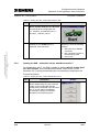
1
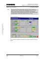
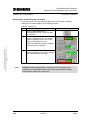
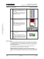
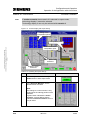
Application about Drive Technology
Technology CPU
Demonstration
Palletizer with simply 3D Interpolating Axes
Based on Cam Discs
Warranty, liability and support
Palletizer 3D – Demonstration
Copyright © Siemens AG 2007 All rights reserved
21062269_Technology_Palletizer3D_Demonstration_DOKU_v3
2_en.doc
Note
ID Number: 21062269
The Application Examples are not binding and do not claim to be
complete regarding the circuits shown, equipping and any eventuality.
The Application Examples do not represent customer-specific solutions.
They are only intended to provide support for typical applications. You
are responsible for ensuring that the described products are correctly
used. These Application Examples do not relieve you of the responsibility
of safely and professionally using, installing, operating and servicing
equipment. When using these Application Examples, you recognize that
Siemens cannot be made liable for any damage/claims beyond the
liability clause described. We reserve the right to make changes to these
Application Examples at any time without prior notice. If there are any
deviations between the recommendations provided in these Application
Examples and other Siemens publications – e.g. Catalogs – then the
contents of the other documents have priority.
Warranty, liability and support
We do not accept any liability for the information contained in this
document.
Any claims against us – based on whatever legal reason – resulting from
the use of the examples, information, programs, engineering and
performance data etc., described in this Application Example shall be
excluded. Such an exclusion shall not apply in the case of mandatory
liability, e.g. under the German Product Liability Act
(“Produkthaftungsgesetz”), in case of intent, gross negligence, or injury of
life, body or health, guarantee for the quality of a product, fraudulent
concealment of a deficiency or breach of a condition which goes to the root
of the contract (“wesentliche Vertragspflichten”). However, claims arising
from a breach of a condition which goes to the root of the contract shall be
limited to the foreseeable damage which is intrinsic to the contract, unless
caused by intent or gross negligence or based on mandatory liability for
injury of life, body or health. The above provisions do not imply a change in
the burden of proof to your detriment.
Copyright© 2007 Siemens A&D. It is not permissible to transfer or
copy these Application Examples or excerpts of them without first
having prior authorization from Siemens A&D in writing.
For questions about this document please use the following e-mail address:
mailto:[email protected]
V3.2
09/11/07
2/52
Foreword
Palletizer 3D – Demonstration
ID Number: 21062269
Foreword
The application described in this document deals with a “palletizer with
simply 3D interpolating axes”. It will be shown how a multidimensional
positioning as, for instance, required for a palletizer can be realized using
the technology CPU.
The core element is the “Move3D” technology template which generates
the cam discs necessary for a three-dimensional motion from an
interpolation point table and which moves the axes at a constant path
velocity.
If you want to obtain further information on the technology template, a
separate documentation is available. The reference data for this
documentation is listed in the appendix of this document.
Objective of the application
Copyright © Siemens AG 2007 All rights reserved
21062269_Technology_Palletizer3D_Demonstration_DOKU_v3
2_en.doc
This application shows the use of one of the technological functions or of a
technology template in the technology CPU.
In order to provide a compact and practical description, a function
frequently used in machines is used in a simple example with HMI
connection. This ensures that the application can also be used as a
demonstration model.
The application illustrates the following:
•
How the used components work together
•
Which technological functions are used
•
How the application is programmed and parameterized
•
How the application can be used as a demonstration system
Main contents of this application
The following main points are described in this application:
•
Use of the “Camming” technology function
•
Use of the “Move3D” technology template
Delimitation
This application does not include a description of…
•
…basic knowledge when using STEP 7
•
…basic knowledge in the field of motion control
•
...the use of technology functions of the technology CPU
•
...the general handling of the technology CPU
Basic knowledge of these topics is required.
V3.2
09/11/07
3/52
Foreword
Palletizer 3D – Demonstration
ID Number: 21062269
Document structure
The documentation of this application is divided into three documents:
•
Introduction
•
Extension
•
Demonstration
In addition, the STEP7 code is available.
The third document, Demonstration, which you are reading right now, is
intended for persons who want to install, test and present the application.
Copyright © Siemens AG 2007 All rights reserved
21062269_Technology_Palletizer3D_Demonstration_DOKU_v3
2_en.doc
Part
Description
Introduction
Application Description
and Principles of
Operation
This part provides a general overview of the
contents. You are informed on the used
components (standard hardware and software
components and the specially created user
software).
Extension
Principles of Operation in
Detail and Program
Structures
This part describes the detailed functional
sequences of the involved hardware and software
components, the solution structures and – where
useful – the specific implementation of this
application.
It is required to read this part if you want to
familiarize with the interaction of the solution
components to use these components, e.g., as a
basis for your own developments.
Demonstration
Structure, Configuration
and Operation of the
Application
This part takes you step by step through structure,
important configuration steps, startup and operation
of the application.
An additional component available is the S7 program code.
Part
S7 program code
Description
The S7 program code includes the code and a user
interface which is also suitable as a demonstration
system.
Reference to Automation and Drives Service & Support
This entry is from the internet application portal of Automation and Drives
Service & Support. The link below takes you directly to the download page
of this document.
http://support.automation.siemens.com/WW/view/en/21062269
V3.2
09/11/07
4/52
Table of Contents
Palletizer 3D – Demonstration
ID Number: 21062269
Table of Contents
1
1.1
1.2
Use of the Application Example .................................................................... 7
Application example with and without real drives ............................................. 7
Structure of this documentation ........................................................................ 7
Copyright © Siemens AG 2007 All rights reserved
21062269_Technology_Palletizer3D_Demonstration_DOKU_v3
2_en.doc
Configuration and Operation....................................................................................... 9
2
2.1
2.1.1
2.1.2
2.2
2.2.1
2.2.2
2.3
2.3.1
2.3.2
2.3.3
2.3.4
2.3.5
2.3.6
Hardware and Software Installation .............................................................. 9
Hardware configuration and installation............................................................ 9
Controller variant with CPU31xT 2DP .............................................................. 9
Embedded variant with Microbox 42x-T ......................................................... 10
SIEMENS standard software installation ........................................................ 10
Required versions........................................................................................... 11
Performing the installation .............................................................................. 11
Downloading user program............................................................................. 11
Preparing the STEP 7 project – controller variant .......................................... 11
Setting the interface on PG/PC and technology CPU – controller variant ...... 12
Downloading the S7 program to the technology CPU – controller variant...... 13
Preparing the STEP 7 project – embedded variant ........................................ 13
Setting the interface on PG/PC and Microbox 42x-T ...................................... 14
Downloading the S7 program to the Microbox 42x-T ..................................... 16
3
3.1
3.2
3.2.1
3.2.2
3.2.3
3.2.4
3.3
3.3.1
3.3.2
3.3.3
3.3.4
3.3.5
3.3.6
Operation of the Application with virtual Axes .......................................... 17
Requirements ................................................................................................. 17
Getting started on demonstrating and presenting........................................... 17
Starting the HMI – controller variant with CPU31xT-2DP ............................... 17
Starting the HMI – embedded variant with Microbox 42x-T ............................ 18
Operating the HMI .......................................................................................... 20
Process display............................................................................................... 22
Detailed operating instructions ....................................................................... 23
Overview of the structure................................................................................ 23
Start screen of the HMI................................................................................... 23
Operating the HMI .......................................................................................... 24
Operator functions in manual mode................................................................ 26
Operator functions in automatic mode ............................................................ 34
Monitoring the technological correlations ....................................................... 39
4
4.1
4.1.1
4.1.2
4.1.3
Connection of real Axes to the Application ............................................... 43
Connecting the SINAMICS S120 training case .............................................. 43
Requirements – SINAMICS S120 on technology CPU................................... 43
Connecting the “Axis” technology objects to the drives .................................. 44
Special parameter settings for the application example ................................. 48
Appendix and Bibliographic References.................................................................. 49
V3.2
09/11/07
5/52
Table of Contents
Palletizer 3D – Demonstration
ID Number: 21062269
Bibliographic References ............................................................................ 49
Bibliographic references ................................................................................. 49
Internet links ................................................................................................... 50
Related documentation................................................................................... 52
6
History ........................................................................................................... 52
Copyright © Siemens AG 2007 All rights reserved
21062269_Technology_Palletizer3D_Demonstration_DOKU_v3
2_en.doc
5
5.1
5.2
5.3
V3.2
09/11/07
6/52
Configuration and Operation
Use of the Application Example
Palletizer 3D – Demonstration
ID Number: 21062269
1
Use of the Application Example
1.1
Application example with and without real drives
This application example can be used to demonstrate and to learn the
functional correlations in the technology CPU as follows:
•
Application example with HMI and virtual axes
•
Application example with HMI and real axes
Copyright © Siemens AG 2007 All rights reserved
21062269_Technology_Palletizer3D_Demonstration_DOKU_v3
2_en.doc
By default, the application example is designed for operation as a
demonstration and example application with virtual axes.
With regard to the application example, the SINAMICS S120 training case
is intended for the connection of real axes to the technology CPU.
However, other drive systems can also be used which can be connected to
the technology CPU via the equidistant PROFIBUS of DP(Drive). For the
respective procedure, please refer to the documentation of the
corresponding drive system.
1.2
Structure of this documentation
Since there are different ways to use the application example with and
without real drives, the documentation is divided as follows:
•
Hardware and Software Installation
•
Operation of the Application with virtual Axes
•
Connection of real Axes to the Application
Hardware and Software Installation
You are provided with all information required for the installation of the
hardware and software components, enabling you to operate the
application example with virtual axes.
The information on the installation of the required hardware for operating
the application example with real axes is provided in the corresponding
section of this documentation.
Operation of the Application with virtual Axes
In this section, you learn how to operate the application example using the
HMI included in the delivery.
The description refers to the delivery status of the application example with
virtual axes.
V3.2
09/11/07
7/52
Configuration and Operation
Use of the Application Example
Palletizer 3D – Demonstration
ID Number: 21062269
Connection of real Axes to the Application
You learn how you can replace the virtual axes of the application example
by real axes and which hardware and software components are required. In
addition, you are provided with notes on the parameterizations necessary
to equip the application example with real axes.
This documentation describes in particular the connection of the SINAMICS
S120 training case to the technology CPU to enable the use of the axes of
the training case together with the application example.
Copyright © Siemens AG 2007 All rights reserved
21062269_Technology_Palletizer3D_Demonstration_DOKU_v3
2_en.doc
To connect other drive systems to the application example, the procedures
listed in this document can be used as a basis and transferred to the
desired drive system.
V3.2
09/11/07
8/52
Configuration and Operation
Hardware and Software Installation
Palletizer 3D – Demonstration
ID Number: 21062269
Configuration and Operation
2
Hardware and Software Installation
2.1
Hardware configuration and installation
2.1.1
Controller variant with CPU31xT 2DP
Operating the application example as a demonstration and sample
application with virtual axes requires a PG/PC and a technology CPU.
Copyright © Siemens AG 2007 All rights reserved
21062269_Technology_Palletizer3D_Demonstration_DOKU_v3
2_en.doc
Figure 2-1 Overview (without power supply)
MPI/DP
Table 2-1 Hardware configuration and installation
No.
V3.2
Instruction
Remark
1.
Mount the PS307 2A power supply
and the CPU on the DIN rail.
2.
Connect the corresponding output
terminals of the PS307 power
supply to the CPU terminals and
connect the mains voltage.
3.
Insert an empty Micro Memory Card
(MMC) into the technology CPU.
Micro Memory Cards which are not
empty have to be cleared in the
PG/PC before they can be used in
the CPU.
4.
Use a PROFIBUS cable to connect
the MPI/DP interface of your PG/PC
to the left MPI/DP interface (contact
X1) of the technology CPU and set
the terminating resistors in the two
terminating plugs of the cable to
“On”.
Do not use the standard MPI cable
delivered with the PG/PC for the
connection between PG/PC and
CPU!
Since the connection should be
operated at a baud rate of 12Mbps,
a PROFIBUS cable with activated
terminating resistors should be used
between PG/PC and CPU.
Otherwise, communication
problems may occur between
PG/PC and CPU.
5.
Switch on all devices.
09/11/07
9/52
Configuration and Operation
Hardware and Software Installation
Palletizer 3D – Demonstration
2.1.2
ID Number: 21062269
Embedded variant with Microbox 42x-T
Figure 2-2 Overview (without power supply)
Industrial Ethernet
Table 2-2 Hardware configuration
Copyright © Siemens AG 2007 All rights reserved
21062269_Technology_Palletizer3D_Demonstration_DOKU_v3
2_en.doc
No.
2.2
Instruction
Remark
1.
Mount the power supply and the
Microbox T on the DIN rail
The device must only be connected
to a 24VDC power supply that
meets safety extra-low voltage
(SELV) requirements.
2.
Before you connect the device to
the power supply, DVI or CRT
monitor, mouse and keyboard must
be connected to ensure that they
are correctly detected by the BIOS
and operating system during
startup.
3.
Connect the power supply via the
plug and switch on the device.
4.
After the startup routine the Logon
dialog box of the Windows XP
Embedded operating system
appears. Enter the user name.
5.
The Microbox 42x-T provides two
Ethernet interfaces.
Use a shielded twisted pair cable.
6.
Connect the Ethernet interface of
your PG/PC to the right Ethernet
port on the Microbox 42x-T (port 2).
In the application example, the
following subnet mask is used:
255.255.255.0.
The default address of Ethernet port
2 is 192.168.0.1.
This address is also used in the
example.
Use the plug included in the delivery
for the connection to the supply
voltage.
SIEMENS standard software installation
Note
V3.2
If you intend to use the application only for demonstration and
presentation purposes, the installation of WinCC flexible 2005 SP1 HF7
Runtime with 512 PowerTags is sufficient. It is not required to install the
engineering system.
09/11/07
10/52
Configuration and Operation
Hardware and Software Installation
Palletizer 3D – Demonstration
2.2.1
ID Number: 21062269
Required versions
The application example is designed and developed for use with the
software components listed in the following table:
Table 2-3 Required versions
Component
STEP 7
5.3 + SP3
S7 Technology
3.0 SP2
WinCC flexible Advanced (incl. Runtime)
2.2.2
Version
2005 SP1 HF7
Performing the installation
Copyright © Siemens AG 2007 All rights reserved
21062269_Technology_Palletizer3D_Demonstration_DOKU_v3
2_en.doc
Install the SIEMENS standard software in the described order and with the
listed options:
•
Step7 including service pack
•
S7 Technology including service pack
•
WinCC flexible Advanced (with the option: Integration in Step7)
or
WinCC flexible Runtime with 512 PowerTags
•
If Runtime is to run on the Microbox 42x-T, WinCC flexible Runtime with
512 PowerTags has to be installed on the Microbox.
Follow the instructions of the corresponding installation program.
2.3
Downloading user program
2.3.1
Preparing the STEP 7 project – controller variant
Prepare the STEP 7 project as follows:
V3.2
•
Open the SIMATIC Manager.
•
Retrieve the STEP 7 archive and then open the retrieved STEP 7
project in the SIMATIC Manager.
09/11/07
11/52
Configuration and Operation
Hardware and Software Installation
Palletizer 3D – Demonstration
2.3.2
ID Number: 21062269
Setting the interface on PG/PC and technology CPU –
controller variant
Since also the large system data blocks of the Runtime software for the
technology have to be transferred to the CPU when downloading the
STEP 7 program to the technology CPU, the interfaces should be set to a
baud rate of 12Mbps.
!
Copyright © Siemens AG 2007 All rights reserved
21062269_Technology_Palletizer3D_Demonstration_DOKU_v3
2_en.doc
Warning
Before changing the interface speed, you should check which
maximum baud rate is supported by your CP or adapter.
If a maximum baud rate of 12Mbps cannot be set and if you load the
application to the CPU without prior changes, you can no longer
access the CPU after downloading!
In this case, set the baud rate of the MPI/DP bus to the maximum
possible transmission rate before downloading.
Setting the PG/PC interface in the Simatic Manager – controller variant
Table 2-4 Setting the PG/PC interface
No.
V3.2
Instruction
1.
In the SIMATIC Manager, click
“Options / Set PG/PC Interface...” to
open the interface configuration.
2.
In the “Interface Parameter
Assignment Used” section, select
the “.....(Auto)” interface setting (e.g.
“CP5512(Auto)”).
3.
Click “Properties” and in the
“Automatic Bus Profile Detection”
tab, set address 0.
09/11/07
Remark
The “...(Auto)” setting should always
be selected for the PG/PC interface.
With this selection the interface
baud rate is automatically
determined and set so that the
module can be accessed without
changing the PG/PC interface
configuration also after the
configuration of the technology CPU
interface.
12/52
Configuration and Operation
Hardware and Software Installation
Palletizer 3D – Demonstration
ID Number: 21062269
Setting the technology CPU interface – controller variant
The interface of the technology CPU has to be set via the HW Config
hardware configuration in the STEP 7 project.
Table 2-5 Setting the technology CPU interface
Copyright © Siemens AG 2007 All rights reserved
21062269_Technology_Palletizer3D_Demonstration_DOKU_v3
2_en.doc
No.
2.3.3
Instruction
Remark
1.
In the SIMATIC Manager, doubleclick “Hardware” to open HW
Config.
2.
Double-click “MPI/DP” to open the
MPI/DP interface settings of the
CPU.
3.
In the “Interface” section, click the
“Properties” button.
4.
Select the corresponding subnet
and click the “Properties” button.
Select subnet MPI(1).
5.
Click “Network Settings” to display
the setting for the transmission rate.
Set the maximum possible baud
rate of your CP or adapter.
6.
Close all screen forms by clicking
OK.
7.
Save and compile the hardware
configuration and download it to the
CPU.
Downloading the S7 program to the technology CPU –
controller variant
To download the STEP 7 program of the sample application to the
technology CPU, proceed as follows:
Table 2-6 Downloading the application to the technology CPU
No.
2.3.4
Instruction
1.
In the SIMATIC Manager, select the
SIMATIC 300(1) station.
2.
Click the “Download” button to
download the entire STEP 7 project
to the technology CPU.
Remark
If prompted with regard to already
existing settings and blocks,
acknowledge by clicking “Yes”.
Preparing the STEP 7 project – embedded variant
Prepare the STEP 7 project as follows:
V3.2
•
Open the SIMATIC Manager.
•
Retrieve the STEP 7 archive and then open the retrieved STEP 7
project in the SIMATIC Manager.
09/11/07
13/52
Configuration and Operation
Hardware and Software Installation
Palletizer 3D – Demonstration
2.3.5
ID Number: 21062269
Setting the interface on PG/PC and Microbox 42x-T
To use the application example, it is not necessary to parameterize the
MPI/DP interface of the Microbox 42x-T. The communication of the
Microbox 42x-T is handled via Industrial Ethernet of the Microbox 42x-T.
However, you can also download the configuration to the Microbox 42x-T
via the MPI/DP interface. To do this, follow the instructions listed in chapter
Setting the interface on PG/PC and technology CPU.
Setting the IP addresses
To communicate via Ethernet, fixed IP addresses have to be set on the
PG and on the Microbox.
Setting the IP address on PG/PC and Microbox 42x-T
Copyright © Siemens AG 2007 All rights reserved
21062269_Technology_Palletizer3D_Demonstration_DOKU_v3
2_en.doc
Follow the steps listed in the table below (first on the SIMATIC Microbox
PC and subsequently the same steps on the programming device).
Table 2-7
No.
V3.2
Instruction
1.
Open the Properties dialog box of the LAN connection you are using by
selecting:
Start Æ Settings Æ Network and Dial-up Connections (in Windows XP:
Network Connections), right-click the LAN connection Æ Properties.
On the Microbox PC, the dialog box is displayed after selecting:
Start Æ Control Panel Æ Network Connections, right mouse click on
Local Area Connection 2 Æ Properties.
2.
In the list, select the “Internet
Protocol (TCP/IP)” entry and click
the “Properties” button.
09/11/07
14/52
Configuration and Operation
Hardware and Software Installation
Palletizer 3D – Demonstration
ID Number: 21062269
Copyright © Siemens AG 2007 All rights reserved
21062269_Technology_Palletizer3D_Demonstration_DOKU_v3
2_en.doc
No.
Instruction
3.
Select the “Use the following IP
address” option for both stations.
4.
Assign the following IP addresses:
SIMATIC Microbox PC: 192.168.0.1
Programming device:
192.168.0.3
Note: Basically, the IP addresses can be freely selected. However, the
addresses have to be different and must only differ in the last digit. They
must correspond to the configuration in the STEP 7 project.
If you are operating your PG on an intranet, you finally have to undo the
above-listed PG settings.
5.
Enter the subnet mask “255.255.255.0” for both stations. The fields for the
default gateway and the DNS servers remain empty.
6.
Confirm the opened dialog boxes with “OK”.
Setting the PG/PC interface in the SIMATIC Manager
Table 2-8 Setting the PG/PC interface
No.
V3.2
Instruction
1.
In the SIMATIC Manager, click
“Options / Set PG/PC Interface...” to
open the interface configuration.
2.
In the “Interface Parameter
Assignment Used” section, select
the “.....(Auto)” interface setting (e.g.
“TCP/IP(Auto)”).
3.
Confirm the settings with OK
09/11/07
Remark
The “...(Auto)” setting should always
be selected for the PG/PC interface.
With this selection the interface
baud rate is automatically
determined and set so that the
module can be accessed without
changing the PG/PC interface
configuration also after the
configuration of the Microbox 42x-T
interface.
15/52
Configuration and Operation
Hardware and Software Installation
Palletizer 3D – Demonstration
ID Number: 21062269
Setting the Microbox 42x-T interface in the hardware configurator
The interface of the Microbox 42x-T has to be set via the HW Config
hardware configuration in the STEP 7 project.
Table 2-9 Setting the Microbox 42x-T interface
Copyright © Siemens AG 2007 All rights reserved
21062269_Technology_Palletizer3D_Demonstration_DOKU_v3
2_en.doc
No.
2.3.6
Instruction
1.
In the SIMATIC Manager,
double-click “Hardware” to open
HW Config.
2.
Double-click “IE General” to open
the Industrial Ethernet module
settings.
3.
Select the Parameters section and,
if necessary, create a new subnet.
4.
Select the corresponding subnet
and enter IP address and subnet
mask.
5.
Close all screen forms by clicking
OK.
6.
Save and compile the hardware
configuration and download it to the
CPU.
Remark
In the example:
IP address 192.168.0.1
Subnet mask 255.255.255.0
Downloading the S7 program to the Microbox 42x-T
To download the STEP 7 program of the sample application to the
Microbox 42x-T, proceed as follows:
Table 2-10 Downloading the application to the Microbox 42x-T
No.
V3.2
Instruction
1.
In the SIMATIC Manager, select
PC Station.
2.
Click the “Download” button to
download the entire STEP 7 project
to the Microbox 42x-T.
09/11/07
Remark
If prompted with regard to already
existing settings and blocks,
acknowledge by clicking “Yes”.
16/52
Configuration and Operation
Operation of the Application with virtual Axes
Palletizer 3D – Demonstration
3
ID Number: 21062269
Operation of the Application with virtual Axes
The application can be used for presenting the technology CPU and the
used technology as well as for familiarizing with and testing the functions of
the CPU.
The following chapters provide a getting started for demonstrating and
presenting the application and an extensive description of all operator
displays and operating options.
3.1
Requirements
Copyright © Siemens AG 2007 All rights reserved
21062269_Technology_Palletizer3D_Demonstration_DOKU_v3
2_en.doc
The following requirements have to be met for operating the application
example with virtual axes:
Note
•
The STEP7 project is online in the technology CPU.
•
At least WinCC flexible 2005 SP1 HF7 Runtime is installed on the
PC/PG or on the Microbox 42x-T.
•
The PG/PC is connected to the technology CPU and the correct baud
rate for the communication is set.
•
The technology CPU is in RUN mode.
WinCC flexible 2005 SP1 HF7 Runtime requires an authorization.
An authorization for at least 512 PowerTags is necessary for the
application example.
Without authorization, a message box indicating the missing authorization
is displayed which can be acknowledged.
3.2
Getting started on demonstrating and presenting
This chapter provides a getting started which enables you to start the
application example as quickly as possible and to demonstrate and present
the essential functions of the application.
3.2.1
Starting the HMI – controller variant with CPU31xT-2DP
On the PG/PC, the HMI is started by starting WinCC flexible 2005 SP1
HF7 Runtime via the Windows “Start” button and by downloading the
corresponding configuration file.
Proceed as follows:
V3.2
09/11/07
17/52
Configuration and Operation
Operation of the Application with virtual Axes
Palletizer 3D – Demonstration
ID Number: 21062269
Table 3-1 Starting the HMI – variant with CPU31xT 2DP
Copyright © Siemens AG 2007 All rights reserved
21062269_Technology_Palletizer3D_Demonstration_DOKU_v3
2_en.doc
No.
3.2.2
Instruction
1.
Start
WinCC flexible 2005 SP1 HF7 Runtime
and download the configuration file:
“C:\...\Palletizer_3D\HmiEs\PROJECT_1\
PROJEKT_1.Palletizer_3D.fwx”
2.
If the connection to the CPU could be
established, the START button is
displayed. Click this button.
Remark
If the START button is not
displayed, check the following
settings:
• Baud rate of the MPI/DP
connection
• Bus connection PG/PC to
the technology CPU
• CPU mode
Starting the HMI – embedded variant with Microbox 42x-T
On the Microbox 42x-T, the HMI is started by starting WinCC flexible 2005
SP1 HF7 Runtime via the Windows Embedded “Start” button (on the
Microbox 42x-T) and by downloading the corresponding configuration file.
Proceed as follows:
Table 3-2 Starting the HMI – variant with Microbox 42x-T
No.
1.
V3.2
Instruction
Remark
Start
WinCC flexible 2005 SP1 HF7 Runtime
Loader. If the configuration file has
already been transferred to the Microbox
42x-T, you can start it immediately.
To transfer the project, proceed as
described in the following points.
09/11/07
18/52
Configuration and Operation
Operation of the Application with virtual Axes
Copyright © Siemens AG 2007 All rights reserved
21062269_Technology_Palletizer3D_Demonstration_DOKU_v3
2_en.doc
Palletizer 3D – Demonstration
V3.2
ID Number: 21062269
2.
In this example, use the following
settings for Channel2:
• Ethernet
• Ensure that Activate and Remote
Control are activated
3.
After you have made the settings, the
Microbox42x-T can be made ready to
receive by selecting the Transfer button.
4.
The WinCC flexible project must be
started on the configuration computer.
To transfer the project, the following
settings have to be made:
• Ethernet mode
• IP address of the Microbox 42x-T
The corresponding figure is
shown at the end of the table
(Figure 3-1).
5.
•
After it has been successfully
transferred, the project starts
automatically. The visualization
can be exited by closing the
window. Via Runtime Loader,
the visualization can be
restarted at any time.
The project can be transferred using
the Transfer button.
09/11/07
19/52
Configuration and Operation
Operation of the Application with virtual Axes
Palletizer 3D – Demonstration
ID Number: 21062269
Figure 3-1 Data transfer settings
Copyright © Siemens AG 2007 All rights reserved
21062269_Technology_Palletizer3D_Demonstration_DOKU_v3
2_en.doc
3.2.3
Operating the HMI
To perform a brief demonstration of the application example, proceed as
follows:
Table 3-3
No.
1.
Instruction
Remark
On the bottom right, please click STOP
and then click the manu
button on the left.
The application is now set to a defined
status and the screen shown on the right
is displayed.
V3.2
2.
Click acknowledge to confirm.
3.
The auto button is now available.
Click this button to change to automatic
mode.
Changing to automatic mode is only
possible if:
• No error is present
• The axes are enabled
• No manual function is activated for
both axes
09/11/07
20/52
Configuration and Operation
Operation of the Application with virtual Axes
Copyright © Siemens AG 2007 All rights reserved
21062269_Technology_Palletizer3D_Demonstration_DOKU_v3
2_en.doc
Palletizer 3D – Demonstration
V3.2
ID Number: 21062269
4.
If the axes are not in starting position,
click the …beam all axes to start
position button to set the
corresponding position value for all axes.
Note:
The button is only displayed when the
axes are not yet in starting position.
5.
In automatic mode, the process display
is displayed.
Click the start
and end buttons in the palletizing
section to turn the palletizing process on
and off.
Use the slider in the velocity section to
change the velocity of the palletizer. A
changed velocity is activated only when
picking up or putting down a box.
Use the slider in the override section to
directly influence the velocity of the
current motion in the range of 0…100%.
6.
Click technology
to show the technology displays. With
the aid of the technology displays, the
used functional mechanisms and
technologies can be explained.
Click technology again to go to the
second technology display. Click
operation
to return to the process display.
7.
In the view status axis / Move3D
section, the status of the axes or of the
technology template can be viewed.
8.
Click operation
to return to the process display.
09/11/07
21/52
Configuration and Operation
Operation of the Application with virtual Axes
Palletizer 3D – Demonstration
3.2.4
ID Number: 21062269
Process display
In automatic mode of the application example, the process display is the
main display for the operation of the palletizer.
Figure 3-2 Process display (automatic mode)
Placed box
Cartesian axis Z
Pallet
Copyright © Siemens AG 2007 All rights reserved
21062269_Technology_Palletizer3D_Demonstration_DOKU_v3
2_en.doc
Travel range
palletizer
Cartesian axis Y
Picking up a
new box
Emergency
stop
Cartesian axis X
Presetting the velocity Setting the override of
of the Cartesian axes the of the Cartesian
X, Y, Z
axes X, Y, Z
Starting and
exiting
expert mode
Starting and
stopping the
palletizing process
Calling the
technology
displays
In the process display, the motion of the palletizer and the palletizing
process can be started, stopped and monitored. In addition, the velocity
and the override of the palletizer can be changed.
Note
Travel range
The parameterization of the interpolation point table has been selected in
such a way that a uniform motion at a constant path velocity of the three
Cartesian axes X, Y and Z can be monitored.
In expert mode, different motion scenarios can be selected so that the
effects of different settings in the interpolation point table on the
application can be monitored.
V3.2
09/11/07
22/52
Configuration and Operation
Operation of the Application with virtual Axes
Palletizer 3D – Demonstration
3.3
ID Number: 21062269
Detailed operating instructions
The following instructions include a detailed and extensive description of
the application as required for familiarizing with and testing the CPU
functions.
3.3.1
Overview of the structure
The figure below shows the basic operating structure including all operator
displays of the application.
Figure 3-3 Overview of the structure
Copyright © Siemens AG 2007 All rights reserved
21062269_Technology_Palletizer3D_Demonstration_DOKU_v3
2_en.doc
Manual Mode
Status
Axes /
Template
Automatic Mode
Technology Mode
Expert Mode
3.3.2
Start screen of the HMI
To adjust the display of the screen form to the current mode of the
application in the controller when starting the HMI, the start screen was
inserted.
Click the Start button to check whether the application is currently in
manual or in automatic mode and subsequently the correct screen form for
the currently active mode is displayed on the HMI.
V3.2
09/11/07
23/52
Configuration and Operation
Operation of the Application with virtual Axes
Palletizer 3D – Demonstration
ID Number: 21062269
Copyright © Siemens AG 2007 All rights reserved
21062269_Technology_Palletizer3D_Demonstration_DOKU_v3
2_en.doc
Figure 3-4 Start screen
3.3.3
Operating the HMI
The basic functions of the application are operated using the buttons in the
bottom right corner of the screen forms (marked red in the screen shot
below) which can be found on almost all screen forms.
V3.2
09/11/07
24/52
Configuration and Operation
Operation of the Application with virtual Axes
Palletizer 3D – Demonstration
ID Number: 21062269
Copyright © Siemens AG 2007 All rights reserved
21062269_Technology_Palletizer3D_Demonstration_DOKU_v3
2_en.doc
Figure 3-5 General displays
The current status is displayed via the button of the respective function; this
is explained below using the example of the auto button:
Table 3-4 Display
Button
Status
Function available
Function activated
Function currently not available
The individual buttons are used to call the following functions:
V3.2
09/11/07
25/52
Configuration and Operation
Operation of the Application with virtual Axes
Palletizer 3D – Demonstration
ID Number: 21062269
Table 3-5 General buttons
Button
Function
Use the STOP button to simultaneously reset the enable for
all axes. All axis motions are immediately stopped and the
motion can only be continued after selecting the
acknowledge button.
Use the acknowledge button to confirm pending error
messages.
(This button is only available in manual mode)
Use the manu button to call setup mode (manual mode).
Use the auto button to call automatic mode.
Copyright © Siemens AG 2007 All rights reserved
21062269_Technology_Palletizer3D_Demonstration_DOKU_v3
2_en.doc
Use the operation button to call the process display in
automatic mode.
Use the technology button to call the technology display in
automatic mode.
With repeated clicks on this button you can change between
the available technology screen forms.
3.3.4
Operator functions in manual mode
In manual mode, you can manually move the axes X and Y of the palletizer.
Three different operator functions are available in this mode.
•
Synchronisation
Homing the axis or setting a specified position.
•
Jog
Manual moving of the axis in jog mode at a preset velocity.
•
Positioning
Positioning the axis to a defined position at a preset velocity.
The Z-axis cannot be accessed in manual mode. In automatic mode, it is
controlled directly via the technology template. A manual moving or homing
of this axis is thus not possible.
However, monitoring the status of the axes X, Y and Z via the
corresponding screen forms of the user interface is possible in all modes.
V3.2
09/11/07
26/52
Configuration and Operation
Operation of the Application with virtual Axes
Palletizer 3D – Demonstration
Note
ID Number: 21062269
Only one of the three manual operator functions can be activated for
each axis at a time. The button is then displayed in green (e.g. Jog).
Before another operator function can be activated, it is required to
terminate the currently activated operator function. This is done by again
clicking the button of the active operator function (e.g. Jog).
Copyright © Siemens AG 2007 All rights reserved
21062269_Technology_Palletizer3D_Demonstration_DOKU_v3
2_en.doc
Figure 3-6 Manual mode
The next section explains the handling of the different operator functions in
detail:
V3.2
09/11/07
27/52
Configuration and Operation
Operation of the Application with virtual Axes
Palletizer 3D – Demonstration
ID Number: 21062269
Enabling axis and monitoring axis status
In manual mode, you can acknowledge errors on the axes or directly
change to the status display of the respective axis.
Table 3-6 Enabling axis
Copyright © Siemens AG 2007 All rights reserved
21062269_Technology_Palletizer3D_Demonstration_DOKU_v3
2_en.doc
No.
Note
V3.2
Action
1.
Click the axis reset button to
acknowledge an error on this axis after
its correction.
2.
Click the enabled/disabled button to
enable or disable the axis. The desired
status is displayed as text, the current
status is indicated by the color.
Green indicates that the axis is enabled,
red shows that it is disabled.
3.
A click in the sensitive section shown in
the figure enables you to directly change
to the status display of the axis.
Remark
enabled is always displayed for virtual axes even if the axis is not
enabled since the display refers to the power section that is always
automatically enabled in virtual axes.
09/11/07
28/52
Configuration and Operation
Operation of the Application with virtual Axes
Palletizer 3D – Demonstration
ID Number: 21062269
Synchronizing or homing axis
Table 3-7 Synchronizing or homing axis
No.
Action
1.
Click the synchronisation button to
activate the synchronization.
2.
In the select mode drop-down list, select
the synchronization type. In the position
to set input box, enter the desired home
position.
Remark
Only one of the three operator
functions can be activated for
each axis at a time.
Copyright © Siemens AG 2007 All rights reserved
21062269_Technology_Palletizer3D_Demonstration_DOKU_v3
2_en.doc
The meaning of the individual modes is
explained in detail in the user manual of
the technology CPU.
To directly apply the entered value, we
recommend mode 3.
Note:
Please do not forget to press ENTER to
confirm the input of the position value.
V3.2
3.
Click the start button to start the
synchronization / homing of the axis.
4.
Click the synchronisation button to
deactivate the synchronization.
09/11/07
When the synchronization of
the axis has been successfully
completed, the done message
is displayed.
29/52
Configuration and Operation
Operation of the Application with virtual Axes
Palletizer 3D – Demonstration
ID Number: 21062269
Manual moving with a preset velocity (JOG)
Copyright © Siemens AG 2007 All rights reserved
21062269_Technology_Palletizer3D_Demonstration_DOKU_v3
2_en.doc
Table 3-8 Manual moving with a preset velocity (JOG)
V3.2
1.
Click the jog button to activate the mode
for manual axis motion.
2.
Use the slider to set the desired velocity.
The selected velocity is shown on the top
right in the display.
3.
Use the jog- or jog+ button to move the
axis in the corresponding direction.
4.
Click the jog button to deactivate the
mode for manual axis motion.
09/11/07
Only one of the three operator
functions can be activated for
each axis at a time.
The axis is moved as long as
the button remains clicked.
30/52
Configuration and Operation
Operation of the Application with virtual Axes
Palletizer 3D – Demonstration
ID Number: 21062269
Absolute positioning
Table 3-9 Absolute positioning
No.
Action
1.
Click the positioning button to activate
the positioning.
2.
Enter the desired position and the
velocity at which the position is to be
approached in the corresponding input
boxes.
If negative values are entered for
velocity, the default velocity defined in
the STEP7 project is used.
Remark
Only one of the three operator
functions can be activated for
each axis at a time.
Copyright © Siemens AG 2007 All rights reserved
21062269_Technology_Palletizer3D_Demonstration_DOKU_v3
2_en.doc
Note:
Please do not forget to press ENTER to
confirm your entries.
V3.2
3.
Click the start button to start the
positioning of the axis.
The axis automatically moves at the set
velocity until the defined target position is
reached.
4.
Click the positioning button to
deactivate the positioning.
09/11/07
Click the cancel button to
cancel the positioning. The
axis is then stopped
immediately.
31/52
Configuration and Operation
Operation of the Application with virtual Axes
Palletizer 3D – Demonstration
ID Number: 21062269
Access to technology parameters
With the technology parameter button you can open the display for
technology parameter access.
Figure 3-7 Technology parameters
Enter the parameter number and the number of the desired technology
data block, thus of the corresponding technology object, to check and
change the technological settings of the controller.
Copyright © Siemens AG 2007 All rights reserved
21062269_Technology_Palletizer3D_Demonstration_DOKU_v3
2_en.doc
Example: Check of the setpoint position of axis 2 via parameter 1 of
technology data block DB 2
Table 3-10 Changing technology parameters
No.
Note
Action
Remark
1.
Enter the number of the desired
parameter in the input box.
Note:
Please do not forget to press ENTER to
confirm your entries!
2.
Enter the number of the desired
technology data block in the input box.
3.
Click the read button to read the settings
of the selected parameter in the
indicated technology block.
The value of the parameter is output in
the display sections according to the
data format.
If reading the parameter has
been successfully completed,
the done message is
displayed, otherwise, an error
message is output.
4.
If you want to write a parameter, enter
the value of the parameter to be written
in the box of the corresponding data
format.
Click the write button to transmit the
write job.
If writing the parameter has
been successfully completed,
the done message is
displayed, otherwise, an error
message is output.
Parameter changes are only stored in the CPU RAM and lost when the
supply voltage is switched off.
A list of the available technology parameters is available in the appendix of
the technology CPU manual.
V3.2
09/11/07
32/52
Configuration and Operation
Operation of the Application with virtual Axes
Palletizer 3D – Demonstration
ID Number: 21062269
Status display of the axes
The status display includes some information from the technology data
block of the axis, e.g. the current velocity and position as well as the status
and error word of the axis.
An exact specification of warning and error messages on the axis is
possible via the ErrorID of the axis. In this display, warning messages are
displayed in yellow and error messages are indicated in red.
An individual status display via which the corresponding axis can be
monitored is available for each axis of the application example.
Copyright © Siemens AG 2007 All rights reserved
21062269_Technology_Palletizer3D_Demonstration_DOKU_v3
2_en.doc
Figure 3-8 Axis status
Use the operation button to return to the basic display of the currently
active mode.
Technology template status
The status display for the technology template displays some information
from the instance data block of the technology template such as status of
the input and output parameters of the function block and the current status
of the technology template.
In addition, an overview of the internal interconnection of the technology
template’s function blocks is provided and the effect of the technology
template’s input and output parameters is illustrated.
V3.2
09/11/07
33/52
Configuration and Operation
Operation of the Application with virtual Axes
Palletizer 3D – Demonstration
ID Number: 21062269
If an error has occurred on the technology template, the ErrorID and the
ErrorSource or the ErrorPoint can also be read in this screen form. After
correcting the error, Stop / Acknowledge can be used to reset the
technology template and the template can be restarted by the user
program.
Copyright © Siemens AG 2007 All rights reserved
21062269_Technology_Palletizer3D_Demonstration_DOKU_v3
2_en.doc
Figure 3-9 Technology template status
Use the operation button to return to the basic display of the currently
active mode.
3.3.5
Operator functions in automatic mode
In automatic mode, the palletizer can be operated in process mode, i.e.
automatically. In addition, different screen forms are available for
monitoring process mode.
V3.2
•
Process display
Monitoring process mode of the palletizer.
•
Expert settings
Option of changing different parameters for process mode.
•
Technology displays
Monitoring the technological correlations of the technology objects
during process mode.
The technology displays will be explained in detail in the next chapter.
09/11/07
34/52
Configuration and Operation
Operation of the Application with virtual Axes
Palletizer 3D – Demonstration
Note
ID Number: 21062269
Automatic mode is available only if there is no failure and if no manual
operator functions are active on the axes.
Process display
Copyright © Siemens AG 2007 All rights reserved
21062269_Technology_Palletizer3D_Demonstration_DOKU_v3
2_en.doc
Figure 3-10 Process display
Table 3-11 Operation in the process display
No.
V3.2
Action
1.
If the axes X, Y and Z are not in the
starting position, a message is displayed.
Click the “…beam all axis to start
position” button to set all axes to the
starting position 0.0.
2.
Click the start button in the palletizing
section to start the palletizer.
09/11/07
Remark
35/52
Configuration and Operation
Operation of the Application with virtual Axes
Palletizer 3D – Demonstration
ID Number: 21062269
3.
Use the velocity slider to set the desired
path velocity. A changed velocity is
activated only when picking up or putting
down a box.
Use the slider in the override section to
directly influence the current motion in
the range of 0…100%.
4.
Monitor the motion process in the
displayed top view or side view.
Copyright © Siemens AG 2007 All rights reserved
21062269_Technology_Palletizer3D_Demonstration_DOKU_v3
2_en.doc
Note:
It is also possible to change to other
operator displays to monitor selected
processes in greater detail while the
motion process is active.
5.
Click end in the palletizing section to
stop the palletizer.
Note:
An active palletizing process is not
interrupted. The palletizer first completes
the current palletizing process and then
stops at the starting position above the
conveyor.
Expert settings
Via the expert settings, different scenarios can be selected for the trajectory
of the palletizing process; the individual scenarios differ in the positions of
the interpolation points and in the definition of the tolerance ranges around
the interpolation points.
The interpolation point tables and radii of the individual scenarios are
permanently stored in the application in data blocks.
Scenario 5 additionally provides the option of temporarily changing
selected values of the interpolation point table by input. When exiting expert
mode or when selecting another scenario, however, the changes made are
lost.
V3.2
09/11/07
36/52
Configuration and Operation
Operation of the Application with virtual Axes
Palletizer 3D – Demonstration
Note
ID Number: 21062269
If another scenario than scenario 0 is selected in expert mode,
technology display 2 cannot be selected.
Technology display 2 can only be selected with scenario 0.
Figure 3-11 Process display with expert setting
Setting of the
interpolation points
Interpolation point
Copyright © Siemens AG 2007 All rights reserved
21062269_Technology_Palletizer3D_Demonstration_DOKU_v3
2_en.doc
Radius around the
interpolation point
Travel path of the
scenarios
Selection of the
scenarios
Table 3-12 Operating the expert settings
1.
Click the expert button in the expert
mode section to start expert mode.
2.
In the Scenario Manager, set the
desired motion scenario.
Note:
The change to a new scenario is only
performed in the starting position of the
palletizer.
A green button indicates the active
scenario. A green flashing button
indicates a selected scenario which is
not yet active.
V3.2
09/11/07
37/52
Configuration and Operation
Operation of the Application with virtual Axes
Copyright © Siemens AG 2007 All rights reserved
21062269_Technology_Palletizer3D_Demonstration_DOKU_v3
2_en.doc
Palletizer 3D – Demonstration
ID Number: 21062269
3.
In the display section, the coordinates of
the current interpolation point table are
displayed, which can vary depending on
the selected scenario.
Interpolation points 6 and 7 are
additionally influenced by the respective
put down position of the box on the
pallet.
4.
The current interpolation points from the
interpolation point table are also entered
in the display of the palletizer.
In addition, the currently active tolerance
radius from the interpolation point table
is visualized around the respective
interpolation point.
5.
In the picture section, a change to the
technology displays is also possible
while expert mode is active.
However, technology display 2 is only
displayed when scenario 0 is active.
6.
Click the expert button in the expert
mode section to exit expert mode.
When exiting expert mode, scenario 0 is
automatically activated when the next
box is picked up.
By selecting the scenario, the following motional sequences can be
selected:
Table 3-13 Possible scenarios
Scenario
V3.2
Description
Note
0
Motional sequence as in automatic mode.
Optimized motional sequence with a
tolerance radius of 50mm.
Optimum motion
control at a constant
path velocity
1
Motional sequence using the motion space
with a tolerance radius of 0mm.
Jerky motion by a
tolerance radius of
0mm.
2
Motional sequence using the motion space
with a tolerance radius of 100mm.
09/11/07
38/52
Configuration and Operation
Operation of the Application with virtual Axes
Palletizer 3D – Demonstration
3.3.6
ID Number: 21062269
3
Motional sequence using the motion space
with a tolerance radius of 250mm.
Optimum motion
control at a constant
path velocity
4
Optimized motional sequence with a
tolerance radius of 0mm.
Jerky motion by a
tolerance radius of
0mm.
5
Values of the interpolation point table that
can be changed as desired. The
changeable values are displayed in yellow
input boxes.
When selecting this
scenario, the settings
of scenario 0 are
loaded.
Monitoring the technological correlations
Copyright © Siemens AG 2007 All rights reserved
21062269_Technology_Palletizer3D_Demonstration_DOKU_v3
2_en.doc
In the picture section, click the technology button to change to the
technology view of the application.
With repeated clicks on the technology button you can change between
the individual technology displays.
Technology display 1: Program execution display
Figure 3-12 Technology display 1
Overview of
functions
Program step
V3.2
Change to
technology display 2
09/11/07
Interpolation
point of the
cam disc
Change to process or
setup display
39/52
Configuration and Operation
Operation of the Application with virtual Axes
Palletizer 3D – Demonstration
ID Number: 21062269
Technology display 1 shows the current status of the STEP7 program. The
overview of functions of the program is dynamically adapted to the current
operation phase of the palletizer or of the technology template. Active
program parts are highlighted, program parts which are not active are
hidden.
The table below lists the possible operation phases and their individual
functions.
Table 3-14 Displayed operation phases
Copyright © Siemens AG 2007 All rights reserved
21062269_Technology_Palletizer3D_Demonstration_DOKU_v3
2_en.doc
Status
V3.2
Remark
Error
An error has occurred in the application.
Check initial conditions
If the axes X, Y and Z are not at the starting
position, “Beam all Axes to Start Position” is used to
move them to this position.
The “Move3D” technology template is reset and
prepared for the start.
The currently selected scenario is checked and, if
required, the scenario is changed.
Use the Start button to restart the palletizer.
Prepare movement
The desired pallet position is determined and
entered in the interpolation point table.
The gripper picks up the box from the conveyor.
Move to target position
(end position)
The parameters for direction of motion, velocity and
override are transferred to the “Move3D” technology
template.
The “Move3D” technology template calculates the
cam discs and starts the travel motion of the axes.
Target reached
The gripper is opened at the desired pallet position
and the box is placed on the pallet.
The “Move3D” technology template is reset and
prepared for the motion to the starting position.
Move to target position
(start position)
The parameters for direction of motion, velocity and
override are transferred to the “Move3D” technology
template.
The “Move3D” technology template calculates the
cam discs for the return and starts the travel motion
back to the starting position.
Assigning scenario
If a new scenario for the motion control has been
selected in expert mode, the parameters for the
“Move3D” technology template are newly set and
the changed interpolation points are entered in the
interpolation point table.
09/11/07
40/52
Configuration and Operation
Operation of the Application with virtual Axes
Palletizer 3D – Demonstration
ID Number: 21062269
Figure 3-13 Possible operation phases of the application
2
Prepare
Movement
Start
3
Move to
Target Position
(End-Pos)
Box lifted
“Move3D” Done
“Move3D” Error
New Scenario
6
Assigning
Scenario
Axes at StartPos
No Error at “Move3D”
1
Initialize
New Scenario Ready
0
Error
4
Target
reached
Homing Error
Box stored
“Move3D” Error
Copyright © Siemens AG 2007 All rights reserved
21062269_Technology_Palletizer3D_Demonstration_DOKU_v3
2_en.doc
“Move3D” Done
5
Move to
Target Position
(Start-Pos)
Technology display 2: Cam disc display
Figure 3-14 Technology display 2
Cam disc
Y-axis
Current position
virtual master
Cam disc
X-axis
Cam disc
Z-axis
Technology display 2 shows the cam discs of the X-, Y- and Z-axis and the
current position of the virtual master. Each time a box is picked up, the cam
discs are recalculated by means of the interpolation point table. The display
of the cam discs enables the user to monitor how the target point on the
V3.2
09/11/07
41/52
Configuration and Operation
Operation of the Application with virtual Axes
Palletizer 3D – Demonstration
ID Number: 21062269
pallet is adjusted for each box while the starting position and the
interpolation points on the trajectory remain unchanged.
The setpoint position of the X-, Y- and Z axis of the palletizer is indicated by
the intersection of the virtual master (red straight line) with the cam disc of
the respective axis. This correlation can best be monitored in the user
interface for the Y-axis of the palletizer.
Figure 3-15 Determining the axis position from the cam disc
Current position
virtual master
Position of the Y-axis
of the palletizer.
Copyright © Siemens AG 2007 All rights reserved
21062269_Technology_Palletizer3D_Demonstration_DOKU_v3
2_en.doc
Cam disc
Y-axis
V3.2
09/11/07
42/52
Configuration and Operation
Connection of real Axes to the Application
Palletizer 3D – Demonstration
4
ID Number: 21062269
Connection of real Axes to the Application
To enable an operation of the application example with real axes, a drive
whose axes are to perform the desired motions can be connected to the
technology CPU.
This requires additional parameterizations in the application example which
will be explained in the following.
4.1
Connecting the SINAMICS S120 training case
For the presentation and operation of the application example with real
axes, the connection of the SINAMICS S120 training case to the
technology CPU will be described in the following sections.
Copyright © Siemens AG 2007 All rights reserved
21062269_Technology_Palletizer3D_Demonstration_DOKU_v3
2_en.doc
Figure 4-1 Technology CPU with HMI and drive
MPI/DP
DP (Drive)
The SINAMICS S120 training case has to be connected and commissioned
by you. For the operation of the application example with the drive, a
STEP 7 archive is not available for download.
Note
Note on the connection of a SINAMICS S120 to the Microbox 42x-T.
To operate the SINAMICS S120 on the Microbox42x-T, proceed as
described on the following pages since the connection of the drive to the
technology of the Microbox 42x-T is identical to the connection to the
technology CPU.
4.1.1
Requirements – SINAMICS S120 on technology CPU
To be able to operate the application example with the drives of the
SINAMICS S120 training case, it is required to include the SINAMICS S120
in the configuration of the application example.
For the connection of the SINAMICS S120 training case to the technology
CPU, an FAQ document can be downloaded from the internet with which
installation and startup of the SINAMICS S120 can be performed on the
technology CPU.
V3.2
09/11/07
43/52
Configuration and Operation
Connection of real Axes to the Application
Palletizer 3D – Demonstration
ID Number: 21062269
Use the following link to download the FAQ document from the internet:
http://support.automation.siemens.com/WW/view/en/21767896
The basic procedure for connecting the SINAMICS S120 training case to
the technology CPU is explained in the table below:
Table 4-1 Connecting the SINAMICS S120 training case to the technology CPU
Copyright © Siemens AG 2007 All rights reserved
21062269_Technology_Palletizer3D_Demonstration_DOKU_v3
2_en.doc
No.
Instruction
1.
Extract the STEP 7 archive of the
application example with virtual
axes.
2.
Open the STEP 7 project for the
application example in the SIMATIC
Manager.
3.
Now follow the instructions of the
FAQ document for the connection of
the SINAMICS S120 to the
technology CPU and use the
STEP 7 project of the application
example as a source project.
Note:
If you want to back up data on the
drive before connecting the
SINAMICS S120, follow the
instructions of the FAQ before
integrating the SINAMICS S120
drive system into the application
example.
4.
Back up the performed
configuration in the STEP 7 project
and in the SINAMICS S120
Remark
Sequence of the activities to be
performed:
• Creating the SINAMICS S120 in
HW Config with corresponding
firmware and connecting to
PROFIBUS DP(Drive).
• Activating the routing in NetPro
for the connection
establishment to the
SINAMICS S120
• Restoring the factory settings
on the SINAMICS S120 as an
initial situation.
• Automatic commissioning of the
Drive-CLiQ components.
• Manual commissioning of the
non Drive-CLiQ components.
Uploading the drive data to the PG
and backing up the data in the
actual drive by copying from RAM to
ROM.
The SINAMICS S120 training case is now prepared for the operation with
the technology CPU.
4.1.2
Connecting the “Axis” technology objects to the drives
In the second step, the “Axis” technology objects of the application example
have to be connected to the real drives of the SINAMICS S120 training
case instead of virtual drives.
V3.2
09/11/07
44/52
Configuration and Operation
Connection of real Axes to the Application
Palletizer 3D – Demonstration
ID Number: 21062269
Data to be set when configuring the technology objects
When configuring the technology objects, the following data has to be
entered in the screen forms in S7T Config.
The second part of this chapter describes how to access these screen
forms.
Table 4-2 Data to be set when configuring the technology objects
Parameter to be set
Technology object
shears axis
Technology object
material line
Axis_X
Axis_Y
Synchronized axis
Synchronized axis
SINAMICS_S120
SINAMICS_S120
SERVO_02
SERVO_03
Message frame
105
105
DSC
Yes
Yes
Maximum speed
6000
6000
Directly to SERVO_02
Directly to SERVO_03
105
105
Absolute value encoder
cyclically absolute
Incremental encoder
EnDat
Sine
Encoder system rotary
Encoder system rotary
Encoder pulses per
revolution
512
2048
Number of data bits
21
---
Multiplication factor
Gn_XIST2
0
---
Multiplication factor
Gn_XIST1
0
0
Encoder monitoring
active
Yes
---
General data
Name
Technology
Drive assignment
Drive unit
Copyright © Siemens AG 2007 All rights reserved
21062269_Technology_Palletizer3D_Demonstration_DOKU_v3
2_en.doc
Drive
Encoder assignment
Connection position
encoder
Message frame
Encoder type
Encoder mode
Measuring system
Encoder data
V3.2
09/11/07
45/52
Configuration and Operation
Connection of real Axes to the Application
Palletizer 3D – Demonstration
ID Number: 21062269
Connecting the technology objects
The connection of a technology object to a drive of the SINAMICS S120
training case is now shown in place of an axis:
Table 4-3 Additional inputs for connecting the axis to a drive
Copyright © Siemens AG 2007 All rights reserved
21062269_Technology_Palletizer3D_Demonstration_DOKU_v3
2_en.doc
No.
V3.2
Instruction
1.
In S7T Config, open the
configuration of the corresponding
axis and run the Wizzard until the
Drive assignment screen form is
displayed.
2.
If a drive unit is not yet offered for
selection in the screen form, click
the Align Sinamics devices…
button to perform an alignment with
the configured drives.
3.
Select the desired drive for the
alignment from the displayed list.
4.
You can now select the drive unit
you want to connect to the Axis
technology object from the
drop-down list.
09/11/07
Remark
46/52
Configuration and Operation
Connection of real Axes to the Application
Copyright © Siemens AG 2007 All rights reserved
21062269_Technology_Palletizer3D_Demonstration_DOKU_v3
2_en.doc
Palletizer 3D – Demonstration
Note
V3.2
ID Number: 21062269
5.
Select the corresponding drive of
the device, define the message
frame for the PROFIBUS
communication and set the
maximum speed of the connected
motor.
For optimum dynamics also activate
Dynamic Servo Control (DSC).
6.
Set Encoder type, Encoder mode
and Measuring system type at the
selected drive.
7.
Set the Encoder pulses per
revolution and the Multiplication
factor of the cyclic actual value of
the encoder.
8.
Click the Finish button to complete
the configuration of the material
axis.
If Dynamic Servo Control (DSC) is activated on the drive, at least
PROFIBUS message frame 105 has to be set for the communication
between technology CPU and drive.
09/11/07
47/52
Configuration and Operation
Connection of real Axes to the Application
Palletizer 3D – Demonstration
4.1.3
ID Number: 21062269
Special parameter settings for the application example
For the application example, the following additional parameter changes
have to be made on the SINAMICS S120 to ensure the operating capability
of the application example together with the drive.
Table 4-4 Special parameter settings on the SINAMICS S120
Parameter
to be set
Drive
SERVO_02
Drive
SERVO_03
Drives / … / open-loop control/closed-loop control / speed controllers
p1300[0]
21
speed control
(with encoder)
21
speed control
(with encoder)
P gain
p1460[0]
0.150
0.150
Reset time
p1462[0]
10.00
10.00
Copyright © Siemens AG 2007 All rights reserved
21062269_Technology_Palletizer3D_Demonstration_DOKU_v3
2_en.doc
Control mode
V3.2
09/11/07
48/52
Appendix and Bibliographic References
Bibliographic References
Palletizer 3D – Demonstration
ID Number: 21062269
Appendix and Bibliographic References
5
Bibliographic References
5.1
Bibliographic references
This list is by no means complete and only provides a selection of
appropriate sources.
Table 5-1
Copyright © Siemens AG 2007 All rights reserved
21062269_Technology_Palletizer3D_Demonstration_DOKU_v3
2_en.doc
Topic
V3.2
Title
/1/
STEP7
Automating with STEP7 in STL and SCL
Hans Berger
Publicis MCD Verlag - 2004
ISBN 3-89578-242-4
/2/
Technology
CPU
SIMATIC – S7-300 CPU Data: CPU 315T-2DP
Siemens Manual
Edition 11/2006
MLFB: A5E00427932-03
/3/
Technology
CPU
SIMATIC – S7-300 CPU Data: CPU 317T-2DP
Siemens Manual
Edition 11/2006
MLFB: A5E00251769-05
/4/
Technology
CPU
SIMATIC – S7 Technology
Siemens Manual
Edition 11/2006
MLFB: A5E00251797-05
/5/
Technology
CPU
Installing SIMATIC Microbox 420-T
Siemens Manual
Edition 06/2006
MLFB: A5E00495804-01
/6/
Technology
CPU
Operating SIMATIC Microbox 420-T
Siemens Manual
Edition 06/2006
MLFB: A5E00495966-01
/7/
Technology
CPU
CPU 317T-2DP: Controlling a SINAMICS S120
Getting Started
Edition 11/2006
MLFB: A5E00480390-02
/8/
Technology
CPU
CPU 317T-2DP: Controlling a virtual axis
Getting Started
Edition 11/2006
MLFB: A5E00266283-04
09/11/07
49/52
Appendix and Bibliographic References
Bibliographic References
Palletizer 3D – Demonstration
ID Number: 21062269
Copyright © Siemens AG 2007 All rights reserved
21062269_Technology_Palletizer3D_Demonstration_DOKU_v3
2_en.doc
Topic
5.2
Title
/9/
Technology
CPU
CPU 317T-2DP: Controlling a physical axis
Getting Started
Edition 11/2006
MLFB: A5E00251785-04
/10/
SINAMICS
S120
SINAMICS S120 – Installation and Start-Up Manual (IH1)
Manufacturer / Service Documentation
Edition 04/2006
MLFB: 6SL3 097-2AF00-0AP5
/11/
SINAMICS
S120
SINAMICS S120 – Equipment Manual (GH1)
Control Units and Additional System Components
Edition 03/2006
MLFB: 6SL3097-2AH00-0AP3
/12/
SINAMICS
S120
SINAMICS S120 – Equipment Manual (GH2)
Booksize Power Sections
Edition 03/2006
MLFB: 6SL3097-2AC00-0AP3
/13/
SINAMICS
S120
SINAMICS S – List Manual (LH1)
Manual
Edition 03/2006
MLFB: 6SL3 097-2AP00-0AP4
/14/
SINAMICS
S120
SINAMICS S120 – Function Manual (FH1)
Function Manual Drive Functions
Manufacturer / Service Documentation
Edition 03/2006
MLFB: 6SL3 097-2AB00-0AP2
Internet links
This list is by no means complete and only provides a selection of
appropriate sources.
Table 5-2
Topic
V3.2
Title
\1\
Reference to
the entry
http://support.automation.siemens.com/WW/view/en/21
062269
\2\
Siemens A&D
Customer
Support
www.ad.siemens.de/support
\3\
Siemens A&D
Applications &
Tools
http://support.automation.siemens.com/WW/view/en/20
208582
09/11/07
50/52
Appendix and Bibliographic References
Bibliographic References
Palletizer 3D – Demonstration
ID Number: 21062269
Topic
\4\
Application
examples for
the technology
CPU
(a selection)
Feeder for a Press:
http://support.automation.siemens.com/WW/view/en/21
363677
Flying Shears with Print-Mark Synchronization Based
on Gear Synchronism:
http://support.automation.siemens.com/WW/view/en/21
063352
\5\
Technology
CPU manual
http://www.ad.siemens.de/support
Select “Product Support”
Open the following directories in the
Product Information tree:
• Automation systems
• SIMATIC Industrial Automation Systems
• PLC
• SIMATIC S7
• S7-300/S7-300F
• CPUs
Click the Manual tab to open a list with related
documents or click the following links:
S7 Technology:
http://support.automation.siemens.com/WW/view/en/22
639716
CPU manual 317T-2 DP:
http://support.automation.siemens.com/WW/view/en/17
993483
CPU manual 315T-2 DP:
http://support.automation.siemens.com/WW/view/en/21
362915
Installing Microbox 420-T:
http://support.automation.siemens.com/WW/view/en/23
999776
Operating Microbox 420-T:
http://support.automation.siemens.com/WW/view/en/23
999030
\6\
SINAMICS
S120
instruction
manual
http://www.ad.siemens.de/support
Select “Product Support”
Open the following directories in the
Product Information tree:
• Drive technology
• AC Converter
• Low voltage converters
• Built-in and cabinet system SINAMICS S120
Click the Manual tab in the right window to open a list
with related documents
or select the following link:
http://www.automation.siemens.com/doconweb
Copyright © Siemens AG 2007 All rights reserved
21062269_Technology_Palletizer3D_Demonstration_DOKU_v3
2_en.doc
V3.2
Title
09/11/07
51/52
Appendix and Bibliographic References
Palletizer 3D – Demonstration
5.3
ID Number: 21062269
Topic
Title
\7\
FAQ
CPU 317T-2 DP
applicable
encoders
Applicable encoders for the technology CPU 31xT in
connection with the drive systems
SIMODRIVE 611U, MASTERDRIVES MC
http://support.automation.siemens.com/WW/view/en/19
968954
\8\
FAQ
technology CPU
version
overview
Which versions of the S7 Technology option package
are available and which SINAMICS S120 drive firmware
can you use with which of these versions?
http://support.automation.siemens.com/WW/view/en/23
411204
Related documentation
Copyright © Siemens AG 2007 All rights reserved
21062269_Technology_Palletizer3D_Demonstration_DOKU_v3
2_en.doc
This list includes a summary of related documentations which you can
obtain from Siemens Customer Support or your Siemens contact person.
Table 5-3
Topic
/A/
6
Technology
template
Title
“Move3D” Technology Template
Technology CPU – Documentation
ID number: 21364022
http://support.automation.siemens.com/WW/view/en/21
364022
History
Table 6-1 History
Version
V3.2
Date
Modification
V3.1
12/05/06
Adaptation of the documentation to the S7 Technology
V3.0 SP1 technology package.
Adding of the Microbox 420-T.
V3.2
09/11/07
Adaptation of the documentation to the S7 Technology
V3.0 SP2 technology package.
Adding of the Microbox 420-T.
Adding of Runtime.
09/11/07
52/52