1
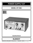
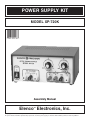
POWER SUPPLY KIT
MODEL XP-720K
Assembly Manual
Elenco Electronics, Inc.
TM
TM
Copyright © 2004, 1998 by Elenco Electronics, Inc. All rights reserved.
Revised 2004
REV-B
No part of this book shall be reproduced by any means; electronic, photocopying, or otherwise without written permission from the publisher.
753269
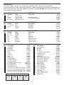
PARTS LIST
If you are a student, and any parts are missing or damaged, please see instructor or bookstore.
If you purchased this kit from a distributor, catalog, etc., please contact Elenco Electronics (address/phone/email is at the back of this manual) for additional assistance, if needed. DO NOT contact your place of purchase
as they will not be able to help you.
TM
RESISTORS
Qty.
1
2
2
2
Symbol
Value
R5
R3, R4
R1, R2
VR1, VR2
.18W 5% 3W
2.7W 5% 1/4W
150W 5% 1/4W
2kW Potentiometer
Color Code
Part #
red-violet-gold-gold
brown-green-brown-gold
101804
112701
131500
192422
Symbol
Value
Description
Part #
C1 - C4, C8
C5, C6
C7
10mF
2200mF
4700mF
Electrolytic
Electrolytic
Electrolytic
271045
292226
294744
Symbol
Value
Description
Part #
D1 - D4
D5 - D8
Q1
Q2
IC1
IC2
IC3
1N4001
1N5400
A70
2N6124
LM-317T
LM-337T
LM-7805CT
Diode
Diode
Transistor
Transistor
Integrated Circuit
Integrated Circuit
Integrated Circuit
314001
315400
320070
326124
330317
330337
337805
CAPACITORS
Qty.
5
2
1
SEMICONDUCTORS
Qty.
4
4
1
1
1
1
1
MISCELLANEOUS
Qty.
1
1
1
1
1
1
1
2
1
5
4
2
7
7
2
3
5
2
4
2
Description
Part#
Qty.
Transformer
440720
PC Board
512013
Fuse 1.25A
530125
Rocker Switch
541204
Cover
611120
Chassis
612012
Heat Sink
615010
Knob
622009
Strain Relief
624003
Insulator Washer
624007
PC Board Stand-off
625001
Black Binding Post
625031
Int. Lockwasher, Binding Post
625031LW
Nut, Binding Post
625031HN
Red Binding Post
625032
Yellow Binding Post
625034
Screw 6-32 x 3/8” Phillips, Pan, Machine 641640
Screw 8-32 x 3/8” Phillips, Pan, Machine 641840
Screw 6 x 3/8” black, AB, Phillips, Truss 642652
Screw 6 x 3/8” black, AB, Phillips, Pan 642660
4
2
2
1
2
2
2
4
1
1
1
1
3
1
6”
48”
48”
48”
1
2”
1.5”
1
Screw Identification
8-32 x 3/8” 6 x 3/8” Black 6 x 3/8” Black
6-32 x 3/8”
Phil., Pan, Machine Phil., Pan, Machine AB, Phillips, Pan AB, Phillips, Truss
-1-
Description
Nut 6-32 Small
Nut 8-32
Nut 7mm
Nut 6-32
Flat Washer 8mm x 14mm
Lockwasher 5/16”
Lockwasher #8
Rubber Feet
Fuse Holder (Upper Body)
Fuse Holder (Lower Body)
Fuse Holder (Hex Nut)
Fuse Holder (Washer)
Mica Insulator
Silicon Grease
20 Ga. Red Wire
22 Ga. Red Wire
22 Ga. Orange Wire
22 Ga. Blue Wire
Line Cord
Shrink Tubing 1/2” Dia.
Shrink Tubing 3/4” Dia.
Solder Tube
Part#
644601
644800
644101
644600
645101
646101
646828
662001
663005UB
663005LB
663005N
663005W
780002
790005
813210
814201
814310
814610
862105
891101
899110
9ST4
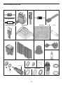
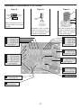
PARTS IDENTIFICATION
Resistor
W Potentiometer
2kW
Capacitor
Diode
Transistor
.18W 3W Resistor
Integrated Circuit
Transformer
Switch
Heatsink
PC Board
Knob
Fuse
Strain Relief
PC Board Stand-off
Binding Post Assembly
Nuts
Mica
Binding Post
6-32 / 8-32
7mm
Nut
Flat Washer
Lockwashers
Lockwasher
#8
-2-
5/16”
Fuse Assembly
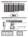
IDENTIFYING RESISTOR VALUES
Use the following information as a guide in properly identifying the value of resistors.
BAND 1
1st Digit
Color
Black
Brown
Red
Orange
Yellow
Green
Blue
Violet
Gray
White
Multiplier
BAND 2
2nd Digit
Digit
0
1
2
3
4
5
6
7
8
9
Color
Black
Brown
Red
Orange
Yellow
Green
Blue
Violet
Gray
White
Resistance
Tolerance
Color
Multiplier
Black
1
Brown
10
Red
100
Orange
1,000
Yellow
10,000
Green
100,000
Blue
1,000,000
Silver
0.01
Gold
0.1
Digit
0
1
2
3
4
5
6
7
8
9
Color
Silver
Gold
Brown
Red
Orange
Green
Blue
Violet
Tolerance
+10%
+5%
+1%
+2%
+3%
+0.5%
+0.25%
+0.1%
BANDS
1
2
Multiplier
Tolerance
IDENTIFYING CAPACITOR VALUES
Capacitors will be identified by their capacitance value in pF (picofarads), nF (nanofarads), or mF (microfarads). Most
capacitors will have their actual value printed on them. Some capacitors may have their value printed in the following
manner. The maximum operating voltage may also be printed on the capacitor.
Multiplier
For the No.
0
1
2
3
Multiply By
1
10
100
1k
4
5
8
10k 100k 0.01
9
0.1
Note: The letter “R” may be used at times
to signify a decimal point; as in 3R3 = 3.3
10mF 16V
First Digit
Second Digit
Multiplier
103K
Tolerance
100V
The letter M indicates a tolerance of +20%
The letter K indicates a tolerance of +10%
The letter J indicates a tolerance of +5%
Maximum Working Voltage
The value is 10 x 1,000 = 10,000pF or .01mF 100V
METRIC UNITS AND CONVERSIONS
Abbreviation
p
n
m
m
–
k
M
Means
Pico
nano
micro
milli
unit
kilo
mega
Multiply Unit By
.000000000001
.000000001
.000001
.001
1
1,000
1,000,000
Or
10-12
10-9
10-6
10-3
100
103
106
1. 1,000 pico units = 1 nano unit
2. 1,000 nano units = 1 micro unit
3. 1,000 micro units= 1 milli unit
4. 1,000 milli units = 1 unit
5. 1,000 units
= 1 kilo unit
6. 1,000 kilo units = 1 mega unit
-3-
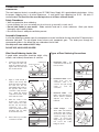
CONSTRUCTION
Introduction
The most important factor in assembling your XP-720K Power Supply Kit is good soldering techniques. Using
the proper soldering iron is of prime importance. A small pencil type soldering iron of 25 - 40 watts is
recommended. The tip of the iron must be kept clean at all times and well tinned.
Safety Procedures
• Wear eye protection when soldering.
• Locate soldering iron in an area where you do not have to go around it or reach over it.
• Do not hold solder in your mouth. Solder contains lead and is a toxic substance. Wash your hands
thoroughly after handling solder.
• Be sure that there is adequate ventilation present.
Assemble Components
In all of the following assembly steps, the components must be installed on the top side of the PC board unless
otherwise indicated. The top legend shows where each component goes. The leads pass through the
corresponding holes in the board and are soldered on the foil side.
Use only rosin core solder of 63/37 alloy.
DO NOT USE ACID CORE SOLDER!
What Good Soldering Looks Like
Types of Poor Soldering Connections
A good solder connection should be bright, shiny,
smooth, and uniformly flowed over all surfaces.
1.
Solder all components from
the copper foil side only.
Push the soldering iron tip
against both the lead and
the circuit board foil.
1. Insufficient heat - the
solder will not flow onto the
lead as shown.
Soldering Iron
Component Lead
Foil
Soldering iron positioned
incorrectly.
Circuit Board
2.
3.
4.
Apply a small amount of
solder to the iron tip. This
allows the heat to leave the
iron and onto the foil.
Immediately apply solder to
the opposite side of the
connection, away from the
iron.
Allow the heated
component and the circuit
foil to melt the solder.
Allow the solder to flow
around the connection.
Then, remove the solder
and the iron and let the
The
connection cool.
solder should have flowed
smoothly and not lump
around the wire lead.
Rosin
2. Insufficient solder - let the
solder flow over the
connection until it is
covered. Use just enough
solder
to
cover
the
connection.
Soldering Iron
Solder
Foil
Solder
Gap
Component Lead
Solder
3. Excessive solder - could
make connections that you
did not intend to between
adjacent foil areas or
terminals.
Soldering Iron
Solder
Foil
4. Solder bridges - occur
when solder runs between
circuit paths and creates a
short circuit. This is usually
caused by using too much
solder.
To correct this,
simply drag your soldering
iron across the solder
bridge as shown.
Here is what a good solder
connection looks like.
-4-
Soldering Iron
Foil
Drag
ASSEMBLE COMPONENTS TO PC BOARD
Figure A
Figure B
Figure C
Flat
Band
Polarity
Mark
1/4”
(–)
(+)
Diodes have polarity. Be sure
that the band is in the correct
direction.
Electrolytics have a polarity
marking indicating the (–)
lead. The PC board is marked
to show the lead position.
D5 - 1N5400 Diode
D6 - 1N5400 Diode
D7 - 1N5400 Diode
D8 - 1N5400 Diode
(see Figure A)
Mount the transistor with the
flat side as shown on the top
legend. Leave 1/4” between
the part and PC board.
D4 - 1N4001 Diode
D3 - 1N4001 Diode
D2 - 1N4001 Diode
D1 - 1N4001 Diode
(see Figure A)
R2 - 150W Resistor
R1 - 150W Resistor
(brn-green-brn-gold)
C1 - 10mF Electrolytic
C2 - 10mF Electrolytic
C3 - 10mF Electrolytic
C4 - 10mF Electrolytic
C8 - 10mF Electrolytic
(see Figure B)
C6 - 2200mF Electrolytic
C5 - 2200mF Electrolytic
(see Figure B)
R3 - 2.7W Resistor
R4 - 2.7W Resistor
(red-violet-gold-gold)
R5 - .18W Resistor
C7 - 4700mF Electrolytic
(see Figure B)
Q1 - A70 Transistor
(see Figure C)
-5-
PC BOARD WIRING
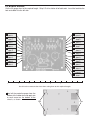
Cut the 22 gauge wires to the required length. Strip 1/4” of insulation off of both ends. Insert the lead into the
hole and solder it to the foil side.
4” Red
Hole K
4” Orange
Hole J
3” Red
Hole I
4” Blue
Hole H
3” Orange
Hole G
4” Blue
Hole F
4” Red
Hole E
6” Blue
Hole D
4” Red
Hole C
0
3 1/2” Red
Hole W
3” Orange
Hole V
3 1/2” Blue
Hole U
3” Blue
Hole T
3 1/2” Orange
Hole S
3” Red
Hole R
4 1/2” Blue
Hole Q
5” Orange
Hole P
4 1/2” Red
Hole O
5” Blue
Hole N
4 1/2” Orange
Hole M
5” Red
Hole L
1
2
3
4
5
6
7
Use this ruler to measure the wires when cutting them to their required lengths.
Peel off the protective paper from the
bottom of the rubber feet and apply one
to each corner on the bottom of the
chassis, as shown.
Feet
Feet
-6-
PANEL ASSEMBLY
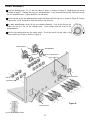
Install the binding posts 1-5 & 7 with the colors in order, as shown in Figure D. Binding post #6 will be
installed on page 7. Remove the large nut and lockwasher. Insert the post into the hole and fasten it with
the nut and lockwasher. Tighten down the nut with pliers.
Cut off the tabs on the two potentiometers and install them with the lugs up, as shown in Figure D. Secure
in place with a 5/16” lockwasher, 8mm flat washer and 7mm nut.
R EAS E
NC
I
Turn both potentiometer shafts all the way counter-clockwise. Line up the line on the
knobs with the first line on the voltage scale. Press knobs onto the shaft of the
potentiometers.
Note the lug configuration on the rocker switch. Push the switch into the hole in the
chassis with lug 1 on top as shown in Figure D.
Potentiometers
* Cut off tabs
5/16” Lockwashers
8mm Washers
7mm Nuts
Nut
Lockwasher
Yellow
1
Black
2
Red
3
Red
4
Yellow
5
Black
2
1
6
Yellow
Lug 1
7
Rocker Switch
3
Rear View of Rocker Switch
-7-
Figure D
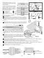
Carefully bend the leads of IC1, IC2,
IC3 and Q2 on the heat sink at right
angles with pliers.
Install IC1, IC2 and Q2 in the positions
shown in Figure E. Fasten in place
using the parts shown in Figure F.
Spread the silicon grease on the back
of the transistor and ICs.
IC1 - LM-317T IC
IC2 - LM-337T IC
Q2 - 2N6124 Transistor
Heatsink
Figure F
6-32 x 3/8”
Screw
2N6124
LM7805T
Mica
Silicon Grease
Small 6-32 Nut
Insulator Washer
IC1, IC2,
Q2
Heat Sink
Figure Fa
LM-317
LM-337T
6-32 x 3/8” Screw
Insulator Washer
Small 6-32 Nut
Mica
Install IC3 as shown in Figure Fa.
IC3 - LM-7805T IC
Figure E
Mount the fuse holder to the top hole in the back of the chassis,
with the side lug up, as shown in Figure G. Fasten in place with
the 3/8” nut. After the holder is secure, unscrew the top and insert
the fuse.
Insulator Washer
IC3
LM7805T
Heat Sink
Side Lug
Separate the wires of the line cord 3” from the end. Strip the
insulation off the end of all two end wires to expose 1/4” of bare wire.
1/4”
Insert 6” of the line cord into the bottom hole on the back of
the chassis, as shown in Figure G. Place the line cord into
the slot of the strain relief and squeeze the two sections
together with pliers. Then, insert the strain relief into the
hole.
One side of the transformer has only 2 black wires. Cut
these wires so that they are 4 1/2” in length (see Figure H).
Strip the insulation off the end of the wires to expose 1/4”
of bare wire. Tin the leads.
Pliers
Smooth
Ribbed
Figure G
Cut the red, blue and black wires on the other side of the transformer so that they are 4” in length. Strip the
insulation off the end of the wires to expose 1/4” of bare wire.
Cut the yellow wires to 6”. Strip the insulation off the end of the wires to expose 1/4” of bare wire.
Install the transformer with the black wires side as shown in Figure J. Use an 8-32 x 3/8” screw, #8
lockwasher and an 8-32 nut on each side to fasten in place, as shown in Figure I.
Install binding post #6 (see Figure D on page 6).
4” Red
4” Red
4” Blue
4 1/2” Black
8-32 Nut
6” Yellow
4” Black
6” Yellow
4” Blue
Figure H
#8 Lockwasher
8-32 x 3/8” Screw
Figure I
-8-
WIRING LINE CORD, FUSE, TRANSFORMER AND SWITCH
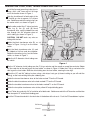
Install the line cord ground lug to the chassis
using a 6-32 x 3/8” screw and a 6-32 large
nut in the location shown in Figure J.
1/2” Tubing
Side Lug
End Lug
Strip the insulation off of both ends of the
6” red 20 ga. wire to expose 1/4” of bare
wire. Solder one end of the wire to lug 3 on
the rocker switch, as shown in Figure J.
Ribbed
Line Cord
U V W
T1CT1 T1
6-32
Large Nut
6-32 x 3/8”
Screw
Red
Red
Blue
Yellow
Black
(B) Black Yellow
Blue
6” 20 Ga.
Red
CAUTION: DO NOT touch any wires or
tubing with the iron.
Solder the black transformer wire (B), as 3/4” Shrink
shown in Figure J to lug 2 on the rocker
Tubing
switch.
Yellow
3
Slide the 3/4” diameter shrink tubing over
the switch.
1 2
Flat or Ribbed Line Cord
Yellow
K
Twist the black transformer wire (A) and
the ribbed or flat line cord wire together.
Solder the two wires to lug 1 on the rocker
switch, as shown in Figure J.
T2 T2
(A) Black
J
Slip the other end of the 6” strip of red wire
(from lug 3), the (A) and (B) black
transformer wire, and the ribbed line cord
wire through the 3/4” diameter piece of
shrink tubing (as shown in Figure J).
Smooth Line Cord
6” Blue
“D” Blue
AC Binding Posts
Figure J
Slip the 1/2” diameter shrink tubing over the 6” 20 ga. red wire and the smooth or round line cord wire. Solder
the line cord wire to the end lug on the fuse holder, as shown in Figure J. Solder the 6” 20 ga. red wire to the
side lug on the fuse holder. Slide the shrink tubing over the fuse holder, covering the two lugs.
Shrink the 1/2” and 3/4” tubings in place using a hair dryer, heat gun (at lowest setting or you will melt the
tubing), or the heat emitting from your soldering iron.
Solder the two red transformer wires to the holes marked T2 on the PC board.
Solder the black transformer wire to the hole marked CT1 on the PC board.
Solder the two blue transformer wires to the holes marked T1 on the PC board.
Solder the two yellow transformer wires to the yellow AC output binding posts.
Cut a 6” blue wire and strip 1/4” of insulation off of both ends. Solder one end of the 6” blue wire and the blue
wire from point “D” to the black binding post.
Push the PC board stand-offs in the four holes in the bottom of the chassis. Push the PC board down in place.
PC Board
Chassis
-9-
WIRE BINDING POSTS AND 317, 337
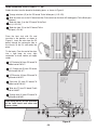
Solder the wires from the board to the binding posts, as shown in Figure K.
3” Orange wire from (G) on the PC board; To the Yellow post (-1.25-15V).
4” Blue wire from (H) on the PC board and the 6” blue wire from the black AC binding post; To the Black post
(common).
3” Red wire from (I) on the PC board; To the Red
post (+1.25-15V).
4” Red wire from (C) on the PC board; To the
Red post (+5V 3A).
Place the heat sink with ICs and
transistor in the position, as shown in
Figure K. Insert the wires from the PC
board, through the rectangular hole in
the chassis, to the ICs and solder into
place.
LM-337
LM-317
Tin the leads. Form the end of the wires
into a tight loop, for easy, tight
connection to leads, before you apply
solder.
3 1/2” Red wire (W) from PC board; To
middle lead of LM-317.
3 1/2” Orange wire (S) from PC board;
To left lead of LM-317.
3 1/2” Blue wire (U) from PC board; To
right lead of LM-317.
W V U T S R
ELENCO ELECTRONICS INC.
XP-620
3” Red
3 1/2” Orange
3” Blue
3 1/2” Blue
3” Orange
3 1/2” Red
3” Red wire (R) from PC board; To
middle lead of LM-337.
3” Blue wire (T) from PC board; To left
lead of LM-337.
3” Orange wire (V) from PC board; To
right lead of LM-337.
I
H G
D
After wiring the ICs, be sure that none
of the leads touch each other and
cause a short.
4” Red
6” Blue
Yellow
Post
C
3” Blue
3” Red
Black
Post
Yellow
Post
6” Blue
Black
Post
Red
Post
Figure K
-10-
Red
Post
3” Orange
Yellow
Post
WIRE 2N6124, 7805 & POTENTIOMETERS
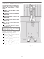
Insert the wires from the PC board through the
rectangular hole in the chassis to the 2N6124
and LM-7805, solder into place, as shown in
Figure L.
7805
2N6124
5” Red wire (L) from the PC board; To middle
lead 0f 2N6124.
5” Orange wire (P) from the PC board; to left
lead of 2N6124.
5” Blue wire (N) from the PC board; to right
lead of 2N6124.
4 1/2” Red wire (O) from PC board; to middle
lead of LM-7805.
4 1/2” Blue wire (Q) from PC board; to left
lead of LM-7805.
Q P O N M L
ELENCO ELECTRONICS INC.
XP-620
5” Red
4 1/2” Orange
5” Blue
4 1/2” Red
5” Orange
4 1/2” Blue
4 1/2” Orange Wire (M) from PC board; to
right lead of LM-7805.
After wiring, be sure that the leads do not touch
each other and cause a short.
4” Red
4” Blue
4” Red wire (E) from PC board; to middle lug
of the positive voltage pot.
4” Orange
4” Red
Solder the wires from the PC board to the
potentiometers, as shown in Figure L.
K J
F E
4” Blue wire (F) from PC board; to right lug
on the positive voltage pot.
4” Orange wire (J) from PC board; to middle
lug on the negative voltage pot.
Potentiometers
4” Red wire (K) from PC board; to right lug
on negative voltage pot.
Positive Voltage
Figure L
-11-
Negative Voltage
FINAL ASSEMBLY
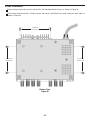
Fasten the heat sink to the chassis with two 6 x 3/8” black pan head screws, as shown in Figure M.
Fit the cover onto the chassis. Fasten in place with two 6 x 3/8” black truss head screws on each side, as
shown in Figure M.
6 x 3/8” Pan
Head Screws
6 x 3/8” Truss
Head Screws
6 x 3/8” Truss
Head Screws
Bottom View
Figure M
-12-
TESTING THE XP-720 POWER SUPPLY
Testing the XP-720 Power Supply is very simple. Before applying power to the unit, be sure that all wiring and
soldering is firm. If so, obtain a digital voltmeter.
1. Apply power to the XP-720 and measure the output voltages.
Output Voltages:
Positive Variable DC
1.25 - 16V
Negative Variable DC
–1.25 - –16V
+5VDC
4.50 - 5.50
12.6VAC
11 - 14
2. Short the output of each of the DC outputs to ground one at a time. ONLY SHORT THE DC OUTPUTS. They
should turn off and recover when the short is removed.
3. Load Test
In making these tests, the voltmeter leads should be clipped to the terminal directly and not the load, to prevent
errors in voltage drop due to contact resistance of the load.
You can use a lower wattage resistor, but only connect it for a few seconds.
Variable DC:
Set the voltage to 10V. Connect a 10W, 10W resistor from the output to ground. The output
should not change more than 0.20V.
+5VDC:
Connect a 2.5W, 12W resistor from the output to ground. The output should not change more
than 0.20V.
Should any of these tests fail, please refer to the troubleshooting guide.
TROUBLESHOOTING GUIDE
No 2 - 15V Output Voltage
1) Check the AC voltage at anode of D1. It should read about 17VAC. If not, check the fuse, transformer, ON/OFF
switch or line cord.
2) Measure voltage at output of D1. It should read about 24VDC. If not, check D1, D3 and C5.
3) If 20V is OK, check IC1.
No Negative Voltage Output
1) Check the voltage at the output of D4. It should be –24VDC. Check D2, D4 and C6 and make sure that they are
not in backwards.
2) If DC is OK, then check IC2.
No 5V Output
1) Check the voltage across the transformer winding. It should read about 12 volts. If not, check the diode bridge or C7.
2) Measure the DC voltage at the output of the diode bridge. It should read about 12 volts. If not, check the diode
bridge or C7.
3) If DC is OK, check IC3, Q1 and Q2.
Poor Regulation on any Supply
1) Check DC voltage at the input of the regulator. It should be greater than 18 for 2 - 15V output and 8V for 5V output.
2) Check AC ripple at the input of the regulator. It should be less than 5V for the variable supply and the 5V supply.
3) If the ripple is greater, then check the diodes and its filter capacitor.
Fails to Shut Down on 5V Overload
1) Check transistor Q1 and resistors R3, R4 and R5.
Unable to Draw 3 Amps at 5 Volts
1) Check transistor Q2 and resistors R3 and R4.
No AC Output
1) Check the power switch and fuse.
2) Check the solder connections to the binding posts.
-13-
CIRCUIT DESCRIPTION
Introduction
The Model XP-720 Power Supply features three solid-state DC power supplies and a 12.6VAC center tapped
output. The first two supplies consist of one positive and one negative 1.25 to 15 volts at 1 ampere. The third
has a fixed 5V at 3 amperes. All DC supplies are fully regulated. A special IC circuit keeps the output voltage
within .2V when going from no load to 1 ampere. The output is fully protected from short circuits. This supply
is ideal for use in school labs, service shops or anywhere a precise DC voltage is required. The AC section has
6.3VAC @ 1A and a 12.6 center tapped @ 1A.
The Positive 1.25-15V Power Supply
Figure 1 shows a simplified circuit diagram of the positive supply. It consists of a power transformer, a DC
rectifier stage and the regulator stage.
120VAC
Input
Transformer
120V to 17V
17VAC
AC to DC
Converter
20VDC
Voltage
Regulator
Simplified diagram of positive power supply
1.25 - 15V
Regulated
Output
Figure 1
Transformer
The transformer T1 serves two purposes. First, it
reduces the 120VAC input to 17VAC to allow the
proper voltage to enter the rectifier stages. Second, it
isolates the power supply output from the 120VAC
line. This prevents the user from dangerous voltage
shock should the user be standing in a grounded area.
Voltage Waveform for Supply
A) Transformer
Winding AB
B) Transformer
Winding BC
AC to DC Converter
The AC to DC converter consists of diodes D1 and D3
and capacitor C5. Transformer T1 has two secondary
windings which are 180 degrees out of phase. The AC
output at each winding is shown in Figure 2A and 2B.
C) Output of
diode D1.
D) Output of
diode D2.
Half Wave Rectifier
Figure 3
E) Total of diodes
D1 & D2.
Diodes are semiconductor devices that allow current
to flow in one direction. The arrow in Figure 3 points
20V
to the direction that the current will flow. Only when
F) Output of capacitor C1
the transformer voltage is positive will current flow
Ripple depends on load
current (expanded).
through the diodes. Figure 3 shows the simplest
Full Wave Rectifier
possible rectifier circuit. This circuit is known as a halfFigure 2
Figure 4
wave rectifier. Here the diode conducts only half of
the time when the AC wave is positive as shown in
Figure 2C. Use of this circuit is simple but inefficient. The big gap between cycles require much more filtering
to obtain a smooth DC voltage.
By addition of a second diode and transformer winding, we can fill in the gap between cycles as shown in
Figure 4. This circuit is called full-wave rectification. Each diode conducts when the voltage is positive. By
adding the two outputs, the voltage presented to capacitor C5 is more complete, thus easier to filter, as shown
in Figure 2E. When used in 60 cycles AC input power, the output of a full wave rectifier will be 120 cycles.
Capacitor C5 is used to store the current charges, thus smoothing the DC voltage. The larger the capacitor, the
more current is stored. In this design, 2200mF capacitors are used, which allows about 3 volts AC ripple when
one amp is drawn.
-14-
In practice, the current through the diodes is not as shown in Figure 2C. Because
capacitor C5 has a charge after the first cycle, the diode will not conduct until the
positive AC voltage exceeds the positive charge in the capacitor. Figure 5 shows
a better picture of what the current flow looks like, assuming no loss in the diode.
It takes a few cycles for the voltage to build up on the capacitor. This depends on
the resistance of the winding and diode. After the initial start-up, there will be a
charge and discharge on the capacitor depending on the current drawn by the
output load. Remember current only flows through the diode when the anode is
more positive than the cathode. Thus, current will flow in short bursts as shown
in Figure 5C.
A) Transformer
Winding
20V
Peak
B) Voltage C1
20V
C) Current
through diodes
Figure 5
The DC load current may be one ampere, but the peak diode current may be three times that. Therefore, the
diode rating must be sufficient to handle the peak current. The 1N4001 has peak current rating of 10 amps.
Regulator Circuit
The regulator circuit in the Model XP-720 power supply consists of a LM-317
integrated circuit. This IC is specially designed to perform the regulation
function. Figure 6 shows a simplified circuit of how the LM-317 IC works.
Transistors Q1 and Q2 form a circuit known as a differential amplifier.
Transistor Q1 base is connected to a stable 1.5V reference voltage. The base
of Q2 is connected to the regulator output circuit through a voltage divider
network. The collector of transistor Q2 is connected to a current source. This
basically is a PNP transistor biased to draw about 1mA of current. Transistor
Q2 sees the current source as a very high resistor of about 1 meg ohms. Thus,
the gain of transistor Q2 is extremely high.
Current
Source
Equalized
to 1 Meg.
Q5
Q3
2V
Output
R1
Q4
Q2
1.5V
R2
Q1
Divider
Figure 6
Transistor Q5 is called the pass transistor. It controls the current reaching the output. Transistors Q3 and Q4
are emitter followers. Their function is to raise the impedance of the pass transistor. Note that transistors Q2,
Q3, Q4 and Q5 and resistor R1 form a close loop. Also, note that the feedback to the base of Q2 is negative,
that is, when the base of Q2 goes positive, the output at emitter Q5 goes negative. Now if the 2V output voltage
goes down because of current drain at the output, the base of Q2 will drop forcing the collector voltage of Q2
to go higher. This will bring the output voltage back to 2V. This is the basis of all negative regulators.
Another feature of the LM-317 regulator is to protect the IC against overload and output shorts. If the IC is
overloaded, the junction of an overload transistor will overheat. A transistor will sense this overheating and shut
down transistor Q5.
-15-
The LM-317 IC is basically a 1.25V regulator. To be able to vary the output
2 - 15V, we stack the IC on a DC voltage as shown in Figure 6A. When VR1
equals 0, the output voltage is 2V as determined by the LM-317 IC. Note that
the voltage across R1 is always 2 volts. When R1 equals VR1, the voltage
across VR1 will equal the two volts across R1, therefore, the output voltage
will be four volts. When VR1 is 5 times R1, the output voltage is 12 volts. As
you can see, varying resistor VR1 will vary the voltage from 1.25V to 15V.
The Negative Voltage Regulator
LM-317
1.25 - 15V
R1
VR1
Figure 6A
The theory of the negative voltage regulator is the same as the previously
discussed positive regulator. The basic differences is that diodes D2 and D4 are reversed, producing a negative
voltage across capacitor C6. The LM-337 IC is designed to operate from a negative supply.
The 5 Volt Power Supply
In the previous discussion of the variable voltage regulators, the ICs can handle about 1A of current. In the
design of the 5V supply, we need 3A of current. To meet this current requirement we must add an external pass
transistor capable of delivering 3A.
Figure 7 shows a simplified 5V regulator with an external PNP pass
transistor. In this circuit, transistor Q1 is a power transistor capable of
delivering over 3A. Transistor Q2 is biased off until the LM-7805 IC
draws about .2A. When .2A is drawn by the LM-7805 IC, the voltage
drop across the 3 ohm resistor is .6V, enough to turn on transistor Q2.
Transistor Q2 takes over and delivers the current to the output. Note that
if the output voltage goes down, the LM-7805 regulator will draw more
current, forcing the output voltage back to 5V. Thus, the LM-7805
regulator controls the output voltage and keeps it at 5V.
Figure 7
Unfortunately, this circuit has no control of the output maximum current. If the output is shorted to ground
transistor Q2 will be overloaded and eventually be damaged. The LM-7805 IC will only draw the .2A it was
designed to handle and never heat up to turn itself off. Another transistor Q1 is added to limit maximum current.
Resistor R5 is added to sense the current in transistor Q2. When approximately 3A is drawn in transistor Q2,
the voltage drop in resistor R5 will turn on transistor Q1. This will force more current in the LM-7805 IC.
Eventually the LM-7805 IC will overheat turning itself off and thus limiting the circuit at about 3.2A.
The first .2A of current is drawn by the LM-7805 IC. The next 3A are drawn by transistor Q2. Thereafter, the
current is drawn by the LM-7805 IC until it overheats and turns itself off. This is a very effective circuit capable
of regulating the output voltage at a constant 5 volts and yet delivering over 3A of current.
AC Power Supply
The section features a 12.6VAC center tapped output. Two secondary windings from the transformer are
connected directly to the yellow binding posts. Connecting from one of the outputs to the center black binding
post will give you 6.3VAC. The maximum output current for 12.6VAC and 6.3VAC is 1A.
This concludes the discussion on the operation of the XP-720 Power Supply.
-16-
QUIZ
1. AC voltage is supplied to the rectifier stages by the . . .
A. step up transformer.
B. step down transformer.
C. 1 to 1 transformer.
D. AC to DC transformer.
2. The secondary windings of the transformer are . . .
A. 90O out of phase.
B. 180O out of phase.
C. 270O out of phase.
D. 320O out of phase.
3. Diodes allow current to flow . . .
A. when the anode is more negative than the cathode.
B. when the cathode is more positive than the anode.
C. in one direction.
D. when a negative or positive voltage is on the anode.
4. What circuit is more efficient for rectifying AC to DC?
A. Hartley oscillator.
B. Half-wave.
C. Schmitt trigger.
D. Full wave.
5. The DC voltage is smoothed by using a . . .
A. half-wave rectification circuit.
B. small value capacitor with a high voltage value.
C. Large value capacitor.
D. 90O out of phase rectification circuit.
6. An inefficient rectification circuit usually contains . . .
A. large gaps between cycles.
B. twice the AC voltage needed.
C. more diodes.
D. all of the above.
7. The maximum current that a diode can handle is determined by . . .
A. the transformer’s current rating.
B. the amount of AC ripple.
C. three times the diode rating.
D. peak current rating.
8. The LM-317 will shut down when . . .
A. the output voltage is too high.
B. no current is being drawn.
C. the junction overheats.
D. the output voltage drops to 1.25V.
9. The LM-317 regulator contains . . .
A. a pass transistor.
B. a constant current source.
C. a differential amplifier.
D. all of the above.
10. The LM-317 is basically . . .
A. a 1.25V regulator.
B. a 6.25V regulator.
C. a 2.5V regulator.
D. a negative voltage regulator.
Answers: 1. B, 2. B, 3. C, 4. D, 5. C, 6. A, 7. D, 8. C, 9. D, 10. A
-17-
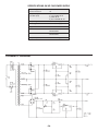
SPECIFICATIONS ON XP-720 POWER SUPPLY
Input Voltage
Current Protection
110-130VAC
1A
Output Voltage
(at 120V input)
1)
2)
3)
4)
1.25-15VDC @ 1A
1.25-15VDC @ 1A
5VDC @ 3A
6.3, 12.6CTAC @ 1A
Output Regulation
200mV each supply
Line Regulation
100mV each supply
Ripple Max
5mV rms
Current Protection
1A limit 2-15VDC
3A limit 5VDC
Short Protection
1A limit 2-15VDC
3A limit 5VDC
Output Impedance
.025W each supply
SCHEMATIC DIAGRAM
-18-
TM
Elenco Electronics, Inc.
150 W. Carpenter Avenue
Wheeling, IL 60090
(847) 541-3800
http://www.elenco.com
e-mail: [email protected]