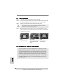
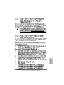
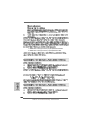
1
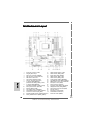
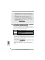
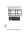
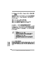
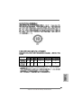
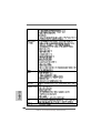
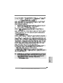
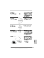
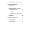
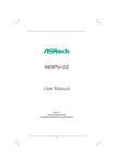
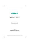
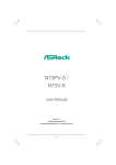
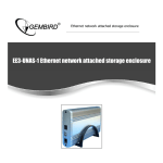
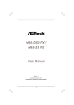
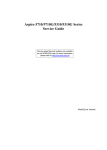
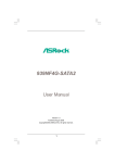
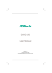
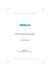
Copyright Notice:
No part of this installation guide may be reproduced, transcribed, transmitted, or translated in any language, in any form or by any means, except duplication of documentation by the purchaser for backup purpose, without written consent of ASRock Inc.
Products and corporate names appearing in this guide may or may not be registered
trademarks or copyrights of their respective companies, and are used only for identification or explanation and to the owners’ benefit, without intent to infringe.
Disclaimer:
Specifications and information contained in this guide are furnished for informational
use only and subject to change without notice, and should not be constructed as a
commitment by ASRock. ASRock assumes no responsibility for any errors or omissions
that may appear in this guide.
With respect to the contents of this guide, ASRock does not provide warranty of any kind,
either expressed or implied, including but not limited to the implied warranties or
conditions of merchantability or fitness for a particular purpose. In no event shall
ASRock, its directors, officers, employees, or agents be liable for any indirect, special,
incidental, or consequential damages (including damages for loss of profits, loss of
business, loss of data, interruption of business and the like), even if ASRock has been
advised of the possibility of such damages arising from any defect or error in the guide
or product.
This device complies with Part 15 of the FCC Rules. Operation is subject to the
following two conditions:
(1) this device may not cause harmful interference, and
(2) this device must accept any interference received, including interference that
may cause undesired operation.
CALIFORNIA, USA ONLY
The Lithium battery adopted on this motherboard contains Perchlorate, a toxic
substance controlled in Perchlorate Best Management Practices (BMP) regulations
English
passed by the California Legislature. When you discard the Lithium battery in
California, USA, please follow the related regulations in advance.
“Perchlorate Material-special handling may apply, see
www.dtsc.ca.gov/hazardouswaste/perchlorate”
ASRock Website: http://www.asrock.com
Published May 2007
Copyright©2007 ASRock INC. All rights reserved.
1
ASRock ALiveNF7G-HD720p Motherboard
Motherboard LLayout
ayout
1
2
3
4
5
6
7
8
English
9
10
11
12
13
14
15
16
Serial Port Connector (COM1)
PS2_USB_PW1 Jumper
ATX Power Connector (ATXPWR1)
ATX 12V Power Connector (ATX12V1)
AM2 940-Pin CPU Socket
CPU Heatsink Retention Module
CPU Fan Connector (CPU_FAN1)
2 x 240-pin DDRII DIMM Slots
(Dual Channel A: DDRII_1, DDRII_2; Yellow)
2 x 240-pin DDRII DIMM Slots
(Dual Channel B: DDRII_3, DDRII_4; Orange)
Primary IDE Connector (IDE1, Blue)
SPI Flash Memory (4Mb)
Clear CMOS Jumper (CLRCMOS1)
Fourth SATAII Connector (SATAII_4 (PORT3))
Chassis Fan Connector (CHA_FAN1)
Secondary SATAII Connector (SATAII_2 (PORT1))
Primary SATAII Connector (SATAII_1 (PORT0))
17
18
19
20
21
22
23
24
25
26
27
28
29
30
31
32
33
USB 2.0 Header (USB10_11, Blue)
USB 2.0 Header (USB8_9, Blue)
System Panel Header (PANEL1)
USB 2.0 Header (USB6_7, Blue)
USB 2.0 Header (USB4_5, Blue)
Chassis Speaker Header (SPEAKER 1)
Third SATAII Connector (SATAII_3 (PORT2))
NVIDIA GeForce 7050 / nForce 630A MCP
PCI Express x1 Slot (PCIE2)
Floppy Connector (FLOPPY1)
Front Panel Audio Header (HD_AUDIO1)
HDMI_SPDIF Header (HDMI_SPDIF1)
Internal Audio Connector: CD1 (Black)
PCI Slots (PCI1- 2)
PCI Express x16 Slot (PCIE1)
Infrared Module Header (IR1)
Game Port Header (GAME1)
2
ASRock ALiveNF7G-HD720p Motherboard
ASRock DVI/H I/O
1
2
3
4
5
6
PS/2 Mouse Port (Green)
Parallel Port
RJ-45 Port
Side Speaker (Gray)
Rear Speaker (Black)
Central / Bass (Orange)
7
Line In (Light Blue)
*8
9
10
11
12
13
14
Front Speaker (Lime)
Microphone (Pink)
USB 2.0 Ports (USB01)
USB 2.0 Ports (USB23)
VGA/D-Sub Port
VGA/DVI-D Port
PS/2 Keyboard Port (Purple)
* If you use 2-channel speaker, please connect the speaker’s plug into “Front Speaker Jack”. See
the table below for connection details in accordance with the type of speaker you use.
TABLE for Audio Output Connection
Audio Output Channels Front Speaker Rear Speaker
(No. 8)
(No. 5)
2
V
-4
V
V
6
V
V
8
V
V
Central / Bass
(No. 6)
--V
V
Side Speaker
(No. 4)
---V
* To enable Multi-Streaming function, you need to connect a front panel audio cable to the front
panel audio header. After restarting your computer, you will find “Mixer” tool on your system.
Please select “Mixer ToolBox”
, click “Enable playback multi-streaming”, and click
* The DVI-D port for the chipset adopted on this motherboard can support DVI/HDCP and HDMI
format signal. You may use the DVI to HDMI adapter to convert this DVI-D port to HDMI
interface. Please follow below steps to enable HDMI audio under Windows® VistaTM / VistaTM
64-bit.
A. Click “Start” button, select “Settings”, and then click “Control Panel”.
B. Click “Hardware and Sound”, and click “Sound”.
C. Change the default setting “Speaker” to “Digital Output Device (HDMI)”.
D. Click “OK” to finish the setting.
Since DVI to HDMI adapter is not bundled with our product, please refer to the adapter vendor for
further information.
ASRock ALiveNF7G-HD720p Motherboard
English
“ok”. Choose “2CH”, “4CH”, “6CH”, or “8CH” and then you are allowed to select “Realtek HDA
Primary output” to use Rear Speaker, Central/Bass, and Front Speaker, or select “Realtek HDA
Audio 2nd output” to use front panel audio.
3
1. Introduction
Thank you for purchasing ASRock ALiveNF7G-HD720p motherboard, a reliable
motherboard produced under ASRock’s consistently stringent quality control. It delivers excellent performance with robust design conforming to ASRock’s commitment to quality and endurance.
This Quick Installation Guide contains introduction of the motherboard and step-bystep installation guide. More detailed information of the motherboard can be found in
the user manual presented in the Support CD.
Because the motherboard specifications and the BIOS software might
be updated, the content of this manual will be subject to change without
notice. In case any modifications of this manual occur, the updated
version will be available on ASRock website without further notice. You
may find the latest VGA cards and CPU support lists on ASRock
website as well.
ASRock website http://www.asrock.com
1.1
Package Contents
1 x ASRock ALiveNF7G-HD720p Motherboard
(Micro ATX Form Factor: 9.6-in x 9.6-in, 24.4 cm x 24.4 cm)
1 x ASRock ALiveNF7G-HD720p Quick Installation Guide
2 x ASRock ALiveNF7G-HD720p Support CD
1 x Ultra ATA 66/100/133 IDE Ribbon Cable (80-conductor)
1 x 3.5-in Floppy Drive Ribbon Cable
1 x Serial ATA (SATA) Data Cable (Optional)
1 x Serial ATA (SATA) HDD Power Cable (Optional)
1 x HDMI_SPDIF Cable (Optional)
1 x ASRock DVI/H I/O Shield
1 x COM Port Bracket
English
4
ASRock ALiveNF7G-HD720p Motherboard
Specifications
Platform
CPU
Chipset
Memory
Hybrid Booster
Expansion Slot
Graphics
Audio
LAN
Rear Panel I/O
- Micro ATX Form Factor: 9.6-in x 9.6-in, 24.4 cm x 24.4 cm
- Socket AM2 for AMD AthlonTM 64FX / 64X2 / X2 / 64 and
Sempron processors
- AMD LIVE!TM Ready
- Supports AMD’s Cool ‘n’ QuietTM Technology
- FSB 1000 MHz (2.0 GT/s)
- Supports Untied Overclocking Technology (see CAUTION 1)
- Supports Hyper-Transport Technology
- NVIDIA® GeForce 7050 / nForce 630A MCP
- Dual Channel DDRII Memory Technology (see CAUTION 2)
- 4 x DDRII DIMM slots
- Support DDRII800/667/533
- Max. capacity: 8GB (see CAUTION 3)
- CPU Frequency Stepless Control (see CAUTION 4)
- ASRock U-COP (see CAUTION 5)
- Boot Failure Guard (B.F.G.)
- ASRock AM2 Boost: ASRock Patented Technology to boost
memory performance up to 12.5% (see CAUTION 6)
- 1 x PCI Express x16 slot
- 1 x PCI Express x1 slot
- 2 x PCI slots
- Integrated NVIDIA® GeForce7 Series (NV44)
- DX9.0 VGA, Pixel Shader 3.0
- Max. shared memory 256MB
- Dual VGA Output: support DVI-D and D-Sub ports by
independent display controllers
- Supports HDCP function with DVI-D port
- Supports 720p Blu-ray (BD) / HD-DVD playback
(see CAUTION 7)
- NVIDIA® PureVideoTM Ready
- 7.1 CH Windows® VistaTM Premium Level HD Audio
(ALC888 Audio Codec)
- Chipset embedded HDMI Audio
- Gigabit LAN 10/100/1000 Mb/s
- Giga PHY Realtek RTL8211B
- Supports Wake-On-LAN
ASRock DVI/H I/O
- 1 x PS/2 Mouse Port
- 1 x PS/2 Keyboard Port
- 1 x VGA/D-Sub Port
ASRock ALiveNF7G-HD720p Motherboard
English
1.2
5
Connector
BIOS Feature
Support CD
Hardware
Monitor
English
OS
Certifications
- 1 x VGA/DVI-D Port (see CAUTION 8)
- 1 x Parallel Port (ECP/EPP Support)
- 4 x Ready-to-Use USB 2.0 Ports
- 1 x RJ-45 Port
- HD Audio Jack: Side Speaker/Rear Speaker/Central/Bass/
Line in/Front Speaker/Microphone (see CAUTION 9)
- 4 x Serial ATAII 3.0Gb/s connectors, support RAID (RAID 0,
RAID 1, RAID 0+1, RAID 5, JBOD), NCQ, AHCI and “Hot Plug”
functions (see CAUTION 10)
- 1 x ATA133 IDE connector (supports 2 x IDE devices)
- 1 x Floppy connector
- 1 x IR header
- 1 x Game header
- 1 x COM port header
- 1 x HDMI_SPDIF header
- CPU/Chassis FAN connector
- 20 pin ATX power connector
- 4 pin 12V power connector
- CD in header
- Front panel audio connector
- 4 x USB 2.0 headers (support 8 USB 2.0 ports)
(see CAUTION 11)
- 4Mb AMI BIOS
- AMI Legal BIOS
- Supports “Plug and Play”
- ACPI 1.1 Compliance Wake Up Events
- Supports jumperfree
- SMBIOS 2.3.1 Support
- Drivers, Utilities, AntiVirus Software (Trial Version)
- CPU Internal Temperature Sensing
- CPU Ambient Temperature Sensing
- Chassis Temperature Sensing
- CPU Fan Tachometer
- Chassis Fan Tachometer
- CPU Quiet Fan
- Voltage Monitoring: +12V, +5V, +3.3V, Vcore
- Microsoft® Windows® 2000/XP/XP Media Center/XP 64-bit/
VistaTM/VistaTM 64-bit compliant (see CAUTION 12)
- FCC, CE, Microsoft® WHQL Certificated
6
ASRock ALiveNF7G-HD720p Motherboard
WARNING
Please realize that there is a certain risk involved with overclocking, including adjusting
the setting in the BIOS, applying Untied Overclocking Technology, or using the thirdparty overclocking tools. Overclocking may affect your system stability, or even
cause damage to the components and devices of your system. It should be done at
your own risk and expense. We are not responsible for possible damage caused by
overclocking.
CAUTION!
2.
3.
4.
5.
6.
7.
8.
9.
This motherboard supports Untied Overclocking Technology. Please read “Untied Overclocking Technology” on page 32 for details.
This motherboard supports Dual Channel Memory Technology. Before you
implement Dual Channel Memory Technology, make sure to read the
installation guide of memory modules on page 13 for proper installation.
Due to the operating system limitation, the actual memory size may be
less than 4GB for the reservation for system usage under Windows® XP
and Windows® VistaTM. For Windows® XP 64-bit and Windows® VistaTM 64bit with 64-bit CPU, there is no such limitation.
Although this motherboard offers stepless control, it is not recommended to
perform over-clocking. Frequencies other than the recommended CPU bus
frequencies may cause the instability of the system or damage the CPU.
While CPU overheat is detected, the system will automatically shutdown.
Before you resume the system, please check if the CPU fan on the motherboard
functions properly and unplug the power cord, then plug it back again. To
improve heat dissipation, remember to spray thermal grease between the
CPU and the heatsink when you install the PC system.
This motherboard supports ASRock AM2 Boost overclocking technology. If
you enable this function in the BIOS setup, the memory performance will
improve up to 12.5%, but the effect still depends on the AM2 CPU you adopt.
Enabling this function will overclock the chipset/CPU reference clock. However,
we can not guarantee the system stability for all CPU/DRAM configurations.
If your system is unstable after AM2 Boost function is enabled, it may not be
applicative to your system. You may choose to disable this function for
keeping the stability of your system.
720p Blu-ray (BD) / HD-DVD playback support on this motherboard requires
the proper hardware configuration. Please refer to page 9 and 10 for the
minimum hardware requirement and the passed 720p Blu-ray (BD) / HD-DVD
films in our lab test.
This DVI-D port for the chipset adopted on this motherboard can support
DVI/HDCP and HDMI format signal. You may use the DVI to HDMI adapter to
convert this DVI-D port to HDMI interface. DVI to HDMI adapter is not bundled
with our product, please refer to the adapter vendor for further information.
For microphone input, this motherboard supports both stereo and mono modes.
For audio output, this motherboard supports 2-channel, 4-channel, 6-channel,
and 8-channel modes. Please check the table on page 3 for proper connection.
English
1.
7
ASRock ALiveNF7G-HD720p Motherboard
10. Before installing SATAII hard disk to SATAII connector, please read the “SATAII
Hard Disk Setup Guide” on page 26 to adjust your SATAII hard disk drive to
SATAII mode. You can also connect SATA hard disk to SATAII connector
directly.
11. Power Management for USB 2.0 works fine under Microsoft® Windows®
VistaTM 64-bit / VistaTM / XP 64-bit / XP SP1 or SP2 / 2000 SP4.
12. Microsoft® Windows® VistaTM / VistaTM 64-bit driver keeps on updating now. As
long as we have the latest driver, we will update it to our website in the future.
Please visit our website for Microsoft® Windows® VistaTM / VistaTM 64-bit driver
and related information.
ASRock website http://www.asrock.com
1.3
Minimum Hardware R
equirement TTable
able for W
indows ®
Requirement
Windows
Vista TM Premium 2007 and Basic Logo
For system integrators and users who purchase this motherboard and
plan to submit Windows® VistaTM Premium 2007 and Basic logo, please follow
below table for minimum hardware requirements.
CPU
Memory
VGA
Sempron 2800+
512MB x 2 Dual Channel (Premium)
512MB Single Channel (Basic)
256MB x 2 Dual Channel (Basic)
DX9.0 with WDDM Driver
DVI with HDCP
English
* If you use onboard VGA with total system memory size 512MB and plan to
submit Windows® VistaTM Basic logo, please adjust the shared memory size of onboard
VGA to 64MB. If you use onboard VGA with total system memory size above 512MB
and plan to submit Windows® VistaTM Premium or Basic logo, please adjust the shared
memory size of onboard VGA to 128MB or above.
* If you plan to use external graphics card on this motherboard, please refer to Premium
Discrete requirement at http://www.asrock.com
* If the onboard VGA supports DVI, it must also support HDCP function to qualify for
Windows® VistaTM Premium 2007 logo.
* After June 1, 2007, all Windows® VistaTM systems are required to meet above
minimum hardware requirements in order to qualify for Windows® VistaTM Premium
2007 logo.
8
ASRock ALiveNF7G-HD720p Motherboard
Minimum Hardware Requirement for 720p Blu-ray (BD)
/ HD-DVD Playback Support
720p Blu-ray (BD) / HD-DVD playback support on this motherboard
requires the proper hardware configuration. Please refer to below table
for the minimum hardware requirement.
CPU
VGA
Memory
Suggested OS
AMD Athlon 64X2 5200+
Onboard VGA with DVI-D port
Dual Channel DDRII800, 1GB x 2
Windows® VistaTM or Windows® VistaTM 64
English
1.4
9
ASRock ALiveNF7G-HD720p Motherboard
1.5
Passed 720p Blu-ray (BD) / HD-DVD Films in Our Lab
T est
DVD
Film Name
Type
Blu-ray SWORDFISH
DVD
UNDERWORLD EVOLUTION
CASINO ROYALE
THE LAST STAND
SPEED
THE LEAGUE OF
EXTRAORDINARY GENTLEMEN
HDKING KONG
DVD
THE INTERPRETER
NEW ORLEANS CONCERT
ONE SIX RIGHT
Format
Producer
VC-1
MPEG-2
MPEG-4-AVC
MPEG-4-AVC
MPEG-4-AVC
MPEG-4-AVC
WB
SONY
SONY
FOX
FOX
FOX
VC-1
MPEG-4-AVC
MPEG-2
MPEG-2
UNIVERSAL
UNIVERSAL
WEA
TERWILLIGER
* MPEG-4-AVC mentioned above refers to the same format of H.264.
* Above passed films are tested under below configuration.
Items
Configurations
CPU
AMD Athlon 64X2 5200+
VGA
Onboard VGA with DVI-D port
Memory
Dual Channel DDRII800, 1GB x 2
OS
Windows® VistaTM or Windows® VistaTM 64
Playback Software
CyberLink PowerDVD Ultra
DVD Player
Pioneer BDR-101A / LG GBW-H10N (BD)
HP HD100 (HD-DVD)
English
10
ASRock ALiveNF7G-HD720p Motherboard
2. Installation
This is a Micro ATX form factor (9.6-in x 9.6-in, 24.4 cm x 24.4 cm) motherboard.
Before you install the motherboard, study the configuration of your chassis to ensure that the motherboard fits into it.
Pre-installation Precautions
Take note of the following precautions before you install motherboard
components or change any motherboard settings.
Before you install or remove any component, ensure that the
power is switched off or the power cord is detached from the
power supply. Failure to do so may cause severe damage to the
motherboard, peripherals, and/or components.
2.
3.
4.
5.
Unplug the power cord from the wall socket before touching any
component.
To avoid damaging the motherboard components due to static
electricity, NEVER place your motherboard directly on the carpet or
the like. Also remember to use a grounded wrist strap or touch a
safety grounded object before you handle components.
Hold components by the edges and do not touch the ICs.
Whenever you uninstall any component, place it on a grounded antistatic pad or in the bag that comes with the component.
When placing screws into the screw holes to secure the motherboard
to the chassis, please do not over-tighten the screws! Doing so may
damage the motherboard.
English
1.
11
ASRock ALiveNF7G-HD720p Motherboard
2.1
CPU Installation
Step 1.
Step 2.
Step 3.
o
Unlock the socket by lifting the lever up to a 90 angle.
Position the CPU directly above the socket such that the CPU corner with
the golden triangle matches the socket corner with a small triangle.
Carefully insert the CPU into the socket until it fits in place.
The CPU fits only in one correct orientation. DO NOT force the CPU
into the socket to avoid bending of the pins.
Step 4.
When the CPU is in place, press it firmly on the socket while you push
down the socket lever to secure the CPU. The lever clicks on the side tab
to indicate that it is locked.
Lever 90° Up
CPU Golden Triangle
Socker Corner Small Triangle
STEP 1:
Lift Up The Socket Lever
STEP 2 / STEP 3:
Match The CPU Golden Triangle
To The Socket Corner Small
Triangle
STEP 4:
Push Down And Lock
The Socket Lever
2.2 Installation of CPU Fan and Heatsink
After you install the CPU into this motherboard, it is necessary to install a
larger heatsink and cooling fan to dissipate heat. You also need to spray
thermal grease between the CPU and the heatsink to improve heat
dissipation. Make sure that the CPU and the heatsink are securely fastened and in good contact with each other. Then connect the CPU fan to
the CPU FAN connector (CPU_FAN1, see Page 2, No. 7). For proper
installation, please kindly refer to the instruction manuals of the CPU fan
and the heatsink.
English
12
ASRock ALiveNF7G-HD720p Motherboard
2.3 Installation of Memory Modules (DIMM)
This motherboard provides four 240-pin DDRII (Double Data Rate II) DIMM slots,
and supports Dual Channel Memory Technology. For dual channel configuration,
you always need to install identical (the same brand, speed, size and chiptype) DDRII DIMM pair in the slots of the same color. In other words, you have to
install identical DDRII DIMM pair in Dual Channel A (DDRII_1 and DDRII_2;
Yellow slots; see p.2 No.8) or identical DDRII DIMM pair in Dual Channel B
(DDRII_3 and DDRII_4; Orange slots; see p.2 No.9), so that Dual Channel Memory
Technology can be activated. This motherboard also allows you to install four
DDRII DIMMs for dual channel configuration, and please install identical DDRII
DIMMs in all four slots. You may refer to the Dual Channel Memory Configuration
Table below.
Dual Channel Memory Configurations
DDRII_1
(Yellow Slot)
Populated
Populated
(1)
(2)
(3)*
DDRII_2
(Yellow Slot)
Populated
Populated
DDRII_3
DDRII_4
(Orange Slot) (Orange Slot)
Populated
Populated
Populated
Populated
* For the configuration (3), please install identical DDRII DIMMs in all four slots.
2.
3.
4.
If you want to install two memory modules, for optimal compatibility
and reliability, it is recommended to install them in the slots of the
same color. In other words, install them either in the set of yellow
slots (DDRII_1 and DDRII_2), or in the set of orange slots (DDRII_3
and DDRII_4).
If only one memory module or three memory modules are installed
in the DDRII DIMM slots on this motherboard, it is unable to activate
the Dual Channel Memory Technology.
If a pair of memory modules is NOT installed in the same Dual
Channel, for example, installing a pair of memory modules in DDRII_1
and DDRII_3, it is unable to activate the Dual Channel Memory
Technology .
It is not allowed to install a DDR memory module into DDRII slot;
otherwise, this motherboard and DIMM may be damaged.
English
1.
13
ASRock ALiveNF7G-HD720p Motherboard
Installing a DIMM
Please make sure to disconnect power supply before adding or
removing DIMMs or the system components.
Step 1.
Step 2.
Unlock a DIMM slot by pressing the retaining clips outward.
Align a DIMM on the slot such that the notch on the DIMM matches the break
on the slot.
The DIMM only fits in one correct orientation. It will cause permanent
damage to the motherboard and the DIMM if you force the DIMM into the
slot at incorrect orientation.
Step 3.
Firmly insert the DIMM into the slot until the retaining clips at both ends fully
snap back in place and the DIMM is properly seated.
English
14
ASRock ALiveNF7G-HD720p Motherboard
2.4 Expansion Slots (PCI and PCI Express Slots)
There are 2 PCI slots and 2 PCI Express slots on this motherboard.
PCI slots: PCI slots are used to install expansion cards that have the 32-bit PCI
interface.
PCIE Slots: PCIE1 (PCIE x16 slot) is used for PCI Express cards with x16 lane
width graphics cards.
PCIE2 (PCIE x1 slot) is used for PCI Express cards with x1 lane
width cards, such as Gigabit LAN card, SATA2 card, etc.
Installing an expansion card
Step 2.
Step 3.
Step 4.
Before installing the expansion card, please make sure that the power
supply is switched off or the power cord is unplugged. Please read the
documentation of the expansion card and make necessary hardware
settings for the card before you start the installation.
Remove the bracket facing the slot that you intend to use. Keep the screws
for later use.
Align the card connector with the slot and press firmly until the card is
completely seated on the slot.
Fasten the card to the chassis with screws.
English
Step 1.
15
ASRock ALiveNF7G-HD720p Motherboard
2.5 Dual Monitor and Surround Display Features
Dual Monitor Feature
This motherboard supports dual monitor feature. With the internal dual VGA output
support (DVI-D and D-Sub), you can easily enjoy the benefits of dual monitor
feature without installing any add-on VGA card to this motherboard. This
motherboard also provides independent display controllers for DVI-D and D-Sub to
support dual VGA output so that DVI-D and D-sub can drive same or different
display contents. To enable dual monitor feature, please follow the below steps:
1. Connect the DVI-D monitor cable to the VGA/DVI-D port on the I/O panel of this
motherboard. Connect the D-Sub monitor cable to the VGA/D-Sub port on the I/O
panel of this motherboard.
VGA/DVI-D port
VGA/D-Sub port
2. If you have installed onboard VGA driver from our support CD to your system
already, you can freely enjoy the benefits of dual monitor function provided by
VGA/DVI-D and VGA/D-Sub ports with this motherboard after your system
boots. If you haven’t installed onboard VGA driver yet, please install onboard
VGA driver from our support CD to your system and restart your computer.
Then you can start to use dual monitor function provided by VGA/DVI-D and
VGA/D-Sub ports with this motherboard.
English
When you playback HDCP-protected video from Blu-ray (BD) or
HD-DVD disc, the content will be displayed only in one of the two
monitors instead of both monitors.
16
ASRock ALiveNF7G-HD720p Motherboard
English
Surround Display Feature
This motherboard supports surround display upgrade. With the internal dual VGA
output support (DVI-D and D-Sub) and the external add-on PCI Express VGA card,
you can easily enjoy the benefits of surround display feature. Please refer to the
following steps to set up a surround display environment:
1. Install the NVIDIA® PCI Express VGA card to PCI Express slot. Please refer to
page 15 for proper expansion card installation procedures for details.
2. Connect the DVI-D monitor cable to the VGA/DVI-D port on the I/O panel of this
motherboard. Connect the D-Sub monitor cable to the VGA/D-Sub port on the I/O
panel of this motherboard.
3. Boot your system. Press <F2> to enter BIOS setup. Enter “Share Memory”
option to adjust the memory capability to [32MB], [64MB], [128MB] or [256MB] to
enable the function of VGA/D-sub. Please make sure that the value you select
is less than the total capability of the system memory. If you do not adjust the
BIOS setup, the default value of “Share Memory”, [Auto], will disable
VGA/D-Sub function when the add-on VGA card is inserted to this
motherboard.
4. Install the onboard VGA driver and the add-on PCI Express VGA card driver to
your system. If you have installed the onboard VGA driver and the add-on PCI
Express VGA card driver already, there is no need to install them again.
5. Set up a multi-monitor display. Right click the desktop, choose “Properties”, and
select the “Settings” tab so that you can adjust the parameters of the multimonitor according to the steps below. (The item names and operation
procedures described in this step are under Windows® XP environment. If you
install other Windows® OS, the item names and operation procedures may be
similar.)
A. Click the “Identify” button to display a large number on each monitor.
B. Right-click the display icon in the Display Properties dialog that you wish to
be your primary monitor, and then select “Primary”. When you use multiple
monitors with your card, one monitor will always be Primary, and all
additional monitors will be designated as Secondary.
C. Select the display icon identified by the number 2.
D. Click “Extend my Windows desktop onto this monitor”.
E. Right-click the display icon and select “Attached”, if necessary.
F. Set the “Screen Resolution” and “Color Quality” as appropriate for the
second monitor. Click “Apply” or “OK” to apply these new values.
G. Repeat steps C through E for the diaplay icon identified by the number one,
two, three and four.
6. Use Surround Display. Click and drag the display icons to positions representing
the physical setup of your monitors that you would like to use. The placement
of display icons determines how you move items from one monitor to another.
17
ASRock ALiveNF7G-HD720p Motherboard
HDCP Function with DVI-D Port
HDCP function is supported with DVI-D port on this motherboard. To
use HDCP function with this motherboard, you need to adopt the
monitor that supports HDCP function as well. Therefore, you can
enjoy the superior display quantity with high-definition HDCP
encryption contents. Please refer to below instruction for more
details about HDCP function.
What is HDCP?
HDCP stands for High-Bandwidth Digital Content Protection, a
specification developed by Intel® for protecting digital entertainment
content that uses the DVI interface. HDCP is a copy protection
scheme to eliminate the possibility of intercepting digital data
midstream between the video source, or transmitter - such as a
computer, DVD player or set-top box - and the digital display, or
receiver - such as a monitor, television or projector. In other words,
HDCP specification is designed to protect the integrity of content as it
is being transmitted.
Products compatible with the HDCP scheme such as DVD players,
satellite and cable HDTV set-top-boxes, as well as few entertainment PCs requires a secure connection to a compliant display. Due
to the increase in manufacturers employing HDCP in their equipment,
it is highly recommended that the HDTV or LCD monitor you purchase
is compatible.
English
18
ASRock ALiveNF7G-HD720p Motherboard
2.6
Jumpers Setup
The illustration shows how jumpers are
setup. When the jumper cap is placed on
pins, the jumper is “Short”. If no jumper cap
is placed on pins, the jumper is “Open”. The
illustration shows a 3-pin jumper whose pin1
and pin2 are “Short” when jumper cap is
placed on these 2 pins.
Jumper
PS2_USB_PW1
Short
Open
Setting
Short pin2, pin3 to enable
+5VSB (standby) for PS/2 or
USB wake up events.
Note: To select +5VSB, it requires 2 Amp and higher standby current provided by
power supply.
(see p.2, No. 2)
Clear CMOS Jumper
(CLRCMOS1)
(see p.2, No. 12)
Default
Clear CMOS
English
Note: CLRCMOS1 allows you to clear the data in CMOS. The data in CMOS includes
system setup information such as system password, date, time, and system
setup parameters. To clear and reset the system parameters to default setup,
please turn off the computer and unplug the power cord from the power
supply. After waiting for 15 seconds, use a jumper cap to short pin2 and pin3
on CLRCMOS1 for 5 seconds. However, please do not clear the CMOS right
after you update the BIOS. If you need to clear the CMOS when you just finish
updating the BIOS, you must boot up the system first, and then shut it down
before you do the clear-CMOS action.
19
ASRock ALiveNF7G-HD720p Motherboard
2.7 Onboard Headers and Connectors
Onboard headers and connectors are NOT jumpers. Do NOT place
jumper caps over these headers and connectors. Placing jumper caps
over the headers and connectors will cause permanent damage of the
motherboard!
•
Floppy Connector
(33-pin FLOPPY1)
(see p.2 No. 26)
the red-striped side to Pin1
Note: Make sure the red-striped side of the cable is plugged into Pin1 side of the
connector.
Primary IDE connector (Blue)
(39-pin IDE1, see p.2 No. 10)
connect the black end
to the IDE devices
connect the blue end
to the motherboard
80-conductor ATA 66/100/133 cable
Note: Please refer to the instruction of your IDE device vendor for the details.
Serial ATAII Connectors
(SATAII_1 (PORT 0 ): see p.2, No. 16)
(SATAII_2 (PORT 1): see p.2, No. 15)
SATAII_4
(PORT 3)
SATAII_2
(PORT 1)
SATAII_3
(PORT 2)
SATAII_1
(PORT 0)
(SATAII_3 (PORT 2): see p.2, No. 23)
(SATAII_4 (PORT 3): see p.2, No. 13)
Serial ATA (SATA)
Data Cable
Either end of the SATA data cable
can be connected to the SATA /
SATAII hard disk or the SATAII
connector on the motherboard.
(Optional)
English
Serial ATA (SATA)
Power Cable
(Optional)
connect to the SATA
HDD power connector
These four Serial ATAII (SATAII)
connectors support SATAII
or SATA hard disk for internal
storage devices. The current
SATAII interface allows up to
3.0 Gb/s data transfer rate.
connect to the
power supply
Please connect the black end of
SATA power cable to the power
connector on each drive. Then
connect the white end of SATA
power cable to the power
connector of the power supply.
20
ASRock ALiveNF7G-HD720p Motherboard
USB 2.0 Headers
Besides four default USB 2.0
ports on the I/O panel, there are
four USB 2.0 headers on this
motherboard. Each USB 2.0
header can support two USB
2.0 ports.
(9-pin USB10_11)
(see p.2 No. 17)
(9-pin USB8_9)
(see p.2 No. 18)
(9-pin USB6_7)
(see p.2 No. 20)
(9-pin USB4_5)
(see p.2 No. 21)
This header supports an
optional wireless transmitting
and receiving infrared module.
(5-pin IR1)
(see p.2 No. 32)
Internal Audio Connectors
(4-pin CD1)
CD1
(CD1: see p.2 No. 29)
Front Panel Audio Header
(9-pin HD_AUDIO1)
(see p.2, No. 27)
This connector allows you
to receive stereo audio input
from sound sources such as
a CD-ROM, DVD-ROM, TV
tuner card, or MPEG card.
English
Infrared Module Header
This is an interface for the front
panel audio cable that allows
convenient connection and
control of audio devices.
21
ASRock ALiveNF7G-HD720p Motherboard
1. High Definition Audio supports Jack Sensing, but the panel wire on the
chassis must support HDA to function correctly. Please follow the
instruction in our manual and chassis manual to install your system.
2. If you use AC’97 audio panel, please install it to the front panel audio
header as below:
A. Connect Mic_IN (MIC) to MIC2_L.
B. Connect Audio_R (RIN) to OUT2_R and Audio_L (LIN) to OUT2_L.
C. Connect Ground (GND) to Ground (GND).
D. MIC_RET and OUT_RET are for HD audio panel only. You don’t
need to connect them for AC’97 audio panel.
E. Enter BIOS Setup Utility. Enter Advanced Settings, and then select
Chipset Configuration. Set the Front Panel Control option from
[Auto] to [Enabled].
F. Enter Windows system. Click the icon on the lower right hand
taskbar to enter Realtek HD Audio Manager.
For Windows® 2000 / XP / XP 64-bit OS:
Click “Audio I/O”, select “Connector Settings”
, choose
“Disable front panel jack detection”, and save the change by
clicking “OK”.
For Windows® VistaTM / VistaTM 64-bit OS:
Click the right-top “Folder” icon
, choose “Disable front
panel jack detection”, and save the change by clicking “OK”.
System Panel Header
This header accommodates
several system front panel
functions.
(9-pin PANEL1)
(see p.2 No. 19)
Chassis Speaker Header
Please connect the chassis
speaker to this header.
(4-pin SPEAKER 1)
(see p.2 No. 22)
English
Chassis Fan Connector
Please connect a chassis fan
cable to this connector and
match the black wire to the
ground pin.
(3-pin CHA_FAN1)
(see p.2 No. 14)
CPU Fan Connector
(4-pin CPU_FAN1)
(see p.2 No. 7)
1 2 3 4
Please connect the CPU fan
cable to this connector and
match the black wire to the
ground pin.
22
ASRock ALiveNF7G-HD720p Motherboard
Though this motherboard provides 4-Pin CPU fan (Quiet Fan) support, the 3-Pin
CPU fan still can work successfully even without the fan speed control function.
If you plan to connect the 3-Pin CPU fan to the CPU fan connector on this
motherboard, please connect it to Pin 1-3.
Pin 1-3 Connected
3-Pin Fan Installation
ATX Power Connector
(20-pin ATXPWR1)
Please connect an ATX power
supply to this connector.
(see p.2 No. 3)
ATX 12V Power Connector
(4-pin ATX12V1)
(see p.2 No. 4)
Game Port Header
(15-pin GAME1)
(see p.2 No. 33)
Serial port Header
(9-pin COM1)
Please note that it is necessary
to connect a power supply with
ATX 12V plug to this connector.
Failing to do so will cause power
up failure.
Connect a Game cable to this
header if the Game port bracket
is installed.
This COM1 header
supports a serial port module.
English
(see p.2 No.1)
23
ASRock ALiveNF7G-HD720p Motherboard
HDMI_SPDIF Header
HDMI_SPDIF header, providing
SPDIF audio output to HDMI VGA
card, allows the system to
connect HDMI Digital TV/
projector/LCD devices. Please
connect the HDMI_SPDIF
connector of HDMI VGA card to
this header.
(3-pin HDMI_SPDIF1)
(see p.2 No. 28)
HDMI_SPDIF Cable
(Optional)
C
B
A
A. black end
B. white end (2-pin)
Please connect the black end (A)
of HDMI_SPDIF cable to the
HDMI_SPDIF header on the
motherboard. Then connect the
white end (B or C) of
HDMI_SPDIF cable to the
HDMI_SPDIF connector of HDMI
VGA card.
C. white end (3-pin)
English
24
ASRock ALiveNF7G-HD720p Motherboard
2.8 HDMI_SPDIF Header Connection Guide
HDMI (High-Definition Multi-media Interface) is an all-digital audio/video specification,
which provides an interface between any compatible digital audio/video source,
such as a set-top box, DVD player, A/V receiver and a compatible digital audio or
video monitor, such as a digital television (DTV). A complete HDMI system requires a
HDMI VGA card and a HDMI ready motherboard with a HDMI_SPDIF header. This
motherboard is equipped with a HDMI_SPDIF header, which provides SPDIF audio
output to HDMI VGA card, allows the system to connect HDMI Digital TV/projector/
LCD devices. To use HDMI function on this motherboard, please carefully follow the
below steps.
•Step 1. Install the HDMI VGA card to the PCI Express Graphics slot on this
Step 2.
motherboard. For the proper installation of HDMI VGA card, please refer
to the installation guide on page 15.
Connect the black end (A) of HDMI_SPDIF cable to the
HDMI_SPDIF header (HDMI_SPDIF1, yellow, see page 2,
No. 28) on the motherboard.
Make sure to correctly connect the HDMI_SPDIF cable to the motherboard and the
HDMI VGA card according to the same pin definition. For the pin definition of
HDMI_SPDIF header and HDMI_SPDIF cable connectors, please refer to page 24. For
the pin definition of HDMI_SPDIF connectors on HDMI VGA card, please refer to the
user manual of HDMI VGA card vendor. Incorrect connection may cause permanent
damage to this motherboard and the HDMI VGA card.
Step 3.
Connect the white end (B or C) of HDMI_SPDIF cable to the HDMI_SPDIF
connector of HDMI VGA card. (There are two white ends (2-pin and 3-pin)
on HDMI_SPDIF cable. Please choose the appropriate white end according
to the HDMI_SPDIF connector of the HDMI VGA card you install.
white end
(2-pin) (B)
white end
(3-pin) (C)
Step 4.
Step 5.
English
Please do not connect the white end of HDMI_SPDIF cable to the wrong connector
of HDMI VGA card or other VGA card. Otherwise, the motherboard and the
VGA card may be damaged. For example, this picture shows the wrong
example of connecting HDMI_SPDIF cable to the fan connector of PCI
Express VGA card. Please refer to the VGA card user manual for
connector usage in advance.
Connect the HDMI output connector on HDMI VGA card to
HDMI device, such as HDTV. Please refer to the user manual
of HDTV and HDMI VGA card vendor for detailed connection
procedures.
Install HDMI VGA card driver to your system.
25
ASRock ALiveNF7G-HD720p Motherboard
2.9
SA
SATTAII Hard Disk Setup Guide
Before installing SATAII hard disk to your computer, please carefully read below
SATAII hard disk setup guide. Some default setting of SATAII hard disks may not be
at SATAII mode, which operate with the best performance. In order to enable SATAII
function, please follow the below instruction with different vendors to correctly
adjust your SATAII hard disk to SATAII mode in advance; otherwise, your SATAII hard
disk may fail to run at SATAII mode.
Western Digital
If pin 5 and pin 6 are shorted, SATA 1.5Gb/s will be enabled.
On the other hand, if you want to enable SATAII 3.0Gb/s, please remove the jumpers
from pin 5 and pin 6.
SAMSUNG
If pin 3 and pin 4 are shorted, SATA 1.5Gb/s will be enabled.
On the other hand, if you want to enable SATAII 3.0Gb/s, please remove the jumpers
from pin 3 and pin 4.
HITACHI
Please use the Feature Tool, a DOS-bootable tool, for changing various ATA features.
Please visit HITACHI’s website for details:
http://www.hitachigst.com/hdd/support/download.htm
The above examples are just for your reference. For different SATAII hard
disk products of different vendors, the jumper pin setting methods may not
be the same. Please visit the vendors’ website for the updates.
English
26
ASRock ALiveNF7G-HD720p Motherboard
2.10
Serial A
ATTA (SA
(SATTA) / Serial A
ATTAII (SA
(SATTAII) Hard Disks
Installation
This motherboard adopts NVIDIA® GeForce 7050 / nForce 630A MCP chipset that
supports Serial ATA (SATA) / Serial ATAII (SATAII) hard disks and RAID functions.
You may install SATA / SATAII hard disks on this motherboard for internal storage
devices. This section will guide you to install the SATA / SATAII hard disks.
STEP 1: Install the SATA / SATAII hard disks into the drive bays of your chassis.
STEP 2: Connect the SATA power cable to the SATA / SATAII hard disk.
STEP 3: Connect one end of the SATA data cable to the motherboard’s SATAII
connector.
STEP 4: Connect the other end of the SATA data cable to the SATA / SATAII hard
disk.
2.11 Hot Plug and Hot Swap FFunctions
unctions for SA
SATTA / SA
SATTAII
HDDs
This motherboard supports Hot Plug and Hot Swap functions for SATA / SATAII
Devices in RAID / AHCI mode. NVIDIA® GeForce 7050 / nForce 630A MCP chipset
provides hardware support for Advanced Host controller Interface (AHCI), a new
operation interface for SATA host controllers developed thru a joint industry effort.
AHCI also provides usability enhancements such as Hot Plug.
NOTE
What is Hot Plug Function?
If the SATA / SATAII HDDs are NOT set for RAID configuration, it is
called “Hot Plug” for the action to insert and remove the SATA / SATAII
HDDs while the system is still power-on and in working condition.
However, please note that it cannot perform Hot Plug if the OS has
been installed into the SATA / SATAII HDD.
What is Hot Swap Function?
English
If SATA / SATAII HDDs are built as RAID 1 or RAID 5 then it is called
“Hot Swap” for the action to insert and remove the SATA / SATAII
HDDs while the system is still power-on and in working condition.
27
ASRock ALiveNF7G-HD720p Motherboard
2.12 Driver Installation Guide
To install the drivers to your system, please insert the support CD to your optical
drive first. Then, the drivers compatible to your system can be auto-detected and
listed on the support CD driver page. Please follow the order from up to bottom
side to install those required drivers. Therefore, the drivers you install can work
properly.
2.13 Installing Windows ® 2000 / XP / XP 64-bit / Vista TM
/ Vista TM 64-bit Without RAID Functions
If you want to install Windows® 2000, Windows® XP, Windows® XP 64-bit, Windows®
Vista TM or Windows ® VistaTM 64-bit on your SATA / SATAII HDDs without RAID
functions, please follow below procedures according to the OS you install.
Before installing Windows® 2000 to your system, your Windows® 2000optical disk
is supposed to include SP4. If there is no SP4 included in your disk, please visit the
below website for proper procedures of making a SP4 disk:
http://www.microsoft.com/Windows2000/downloads/servicepacks/sp4/spdeploy.
htm#the_integrated_installation_fmay
2.13.1 Installing Windows ® 2000 / XP / XP 64-bit Without
RAID Functions
If you want to install Windows® 2000 / Windows® XP / Windows® XP 64-bit on your
SATA / SATAII HDDs without RAID functions, please follow below steps.
Using SATA / SATAII HDDs with NCQ and Hot Plug functions
English
STEP 1: Set Up BIOS.
A.
Enter BIOS SETUP UTILITY
Advanced screen
IDE Configuration.
B.
Set the “SATA Operation Mode” option to [AHCI].
STEP 2: Make a SATA / SATAII driver diskette.
A.
Insert the ASRock Support CD into your optical drive to boot your system.
(There are two ASRock Support CD in the motherboard gift box pack,
please choose the one for Windows® 2000 / XP / XP 64-bit.)
B.
During POST at the beginning of system boot-up, press <F11> key, and
then a window for boot devices selection appears. Please select CDROM as the boot device.
C.
When you see the message on the screen, “Generate Serial ATA driver
diskette [YN]?”, press <Y>.
28
ASRock ALiveNF7G-HD720p Motherboard
D.
Then you will see these messages,
Please choose:
1. Generate AHCI Driver diskette for Windows2000/XP
2. Generate RAID Driver diskette for Windows2000/XP
3. Generate AHCI Driver diskette for WindowsXP64
4. Generate RAID Driver diskette for WindowsXP64
5. Exit
Reboot system now
Press any key to continue
Please insert a floppy diskette into the floppy drive. Select your required
item on the list according to the mode you choose and the OS you install.
Then press any key.
E.
The system will start to format the floppy diskette and copy SATA /
SATAII drivers into the floppy diskette.
STEP 3: Install Windows® 2000 / XP / XP 64-bit OS on your system.
After making a SATA / SATAII driver diskette, you can start to install Windows® 2000
/ XP / XP 64-bit on your system. At the beginning of Windows® setup, press F6 to
install a third-party AHCI driver. When prompted, insert the SATA / SATAII driver
diskette containing the NVIDIA® AHCI driver. After reading the floppy disk, the driver
will be presented. Select the driver to install according to the OS you install. The
drivers are as below:
A. NVIDIA nForce Storage Controller (required) Windows XP/2000
B. NVIDIA nForce Storage Controller (required) Windows XP64
Please select A for Windows® 2000 / XP in AHCI mode. Please select B for Windows®
XP 64-bit in AHCI mode.
Using SATA / SATAII HDDs without NCQ and Hot Plug functions
English
STEP 1: Set Up BIOS.
A.
Enter BIOS SETUP UTILITY
Advanced screen
IDE Configuration.
B.
Set the “SATA Operation Mode” option to [non-RAID].
STEP 2: Install Windows® 2000 / XP / XP 64-bit OS on your system.
29
ASRock ALiveNF7G-HD720p Motherboard
2.13.2 Installing Windows ® Vista TM / Vista TM 64-bit Without
RAID Functions
If you want to install Windows® VistaTM / Windows® VistaTM 64-bit on your SATA /
SATAII HDDs without RAID functions, please follow below steps.
Using SATA / SATAII HDDs with NCQ and Hot Plug functions
STEP 1: Set Up BIOS.
A.
Enter BIOS SETUP UTILITY
Advanced screen
IDE Configuration.
B.
Set the “SATA Operation Mode” option to [AHCI].
STEP 2: Install Windows® VistaTM / VistaTM 64-bit OS on your system.
Insert the Windows® VistaTM / Windows® VistaTM 64-bit optical disk into the optical
drive to boot your system, and follow the instruction to install Windows® VistaTM /
Windows® VistaTM 64-bit OS on your system. When you see “Where do you want to
install Windows?” page, please insert the ASRock Support CD into your optical drive,
and click the “Load Driver” button on the left on the bottom to load the NVIDIA® AHCI
drivers. NVIDIA® AHCI drivers are in the following path in our Support CD:
(There are two ASRock Support CD in the motherboard gift box pack, please
choose the one for Windows® VistaTM / VistaTM 64-bit.)
.. \ I386 \ AHCI_Vista (For Windows® VistaTM OS)
.. \ AMD64\ AHCI_Vista64 (For Windows® VistaTM 64-bit OS)
After that, please insert Windows® VistaTM / Windows® VistaTM 64-bit optical disk into
the optical drive again to continue the installation.
Using SATA / SATAII HDDs without NCQ and Hot Plug functions
STEP 1: Set Up BIOS.
A.
Enter BIOS SETUP UTILITY
Advanced screen
IDE Configuration.
B.
Set the “SATA Operation Mode” option to [non-RAID].
STEP 2: Install Windows® VistaTM / VistaTM 64-bit OS on your system.
Insert the Windows® VistaTM / Windows® VistaTM 64-bit optical disk into the optical
drive to boot your system, and follow the instruction to install Windows® VistaTM /
Windows® VistaTM 64-bit OS on your system.
English
2.14 Installing Windows ® 2000 / XP / XP 64-bit / Vista TM
/ Vista TM 64-bit With RAID Functions
If you want to install Windows® 2000, Windows® XP, Windows® XP 64-bit, Windows®
VistaTM or Windows® VistaTM 64-bit on your SATA / SATAII HDDs with RAID functions,
please follow below procedures according to the OS you install.
30
ASRock ALiveNF7G-HD720p Motherboard
Before installing Windows® 2000 to your system, your Windows® 2000optical disk
is supposed to include SP4. If there is no SP4 included in your disk, please visit the
below website for proper procedures of making a SP4 disk:
http://www.microsoft.com/Windows2000/downloads/servicepacks/sp4/spdeploy.
htm#the_integrated_installation_fmay
2.14.1 Installing Windows ® 2000 / XP / XP 64-bit With RAID
Functions
If you want to install Windows® 2000 / Windows® XP / Windows® XP 64-bit on your
SATA / SATAII HDDs with RAID functions, please follow below steps.
STEP 1: Set Up BIOS.
A.
Enter BIOS SETUP UTILITY
Advanced screen
IDE Configuration.
B.
Set the “SATA Operation Mode” option to [RAID].
STEP 2: Make a SATA / SATAII driver diskette.
Please make a SATA / SATAII driver diskette by following section 2.13.1 step 2 on
page 28.
STEP 3: Use “RAID Installation Guide” to set RAID configuration.
Before you start to configure RAID function, you need to check the RAID installation
guide in the Support CD for proper configuration. Please refer to the BIOS RAID
installation guide part of the document in the following path in the Support CD:
.. \ RAID Installation Guide
STEP 4: Install Windows® 2000 / XP / XP 64-bit OS on your system.
After step1, 2, 3, you can start to install Windows® 2000 / Windows® XP / Windows®
XP 64-bit OS on your system. At the beginning of Windows® setup, press F6 to install
a third-party RAID driver. When prompted, insert the SATA / SATAII driver diskette
containing the NVIDIA® RAID driver. After reading the floppy disk, the drivers will be
presented. Select the drivers to install. The drivers are as below:
A. NVIDIA RAID Driver (required)
B. NVIDIA nForce Storage Controller (required)
Please select A and B for Windows® 2000 / XP / XP 64-bit in RAID mode. (There are
two RAID drivers needed for RAID mode, you have to select them separately. Please
specify the first RAID driver and then specify again for the second one.)
English
NOTE. If you install Windows® 2000 / Windows® XP / Windows® XP 64-bit on IDE
HDDs and want to manage (create, convert, delete, or rebuild) RAID functions
on SATA / SATAII HDDs, you still need to set up “SATA Operation Mode” to [RAID]
in BIOS first. Then, please set the RAID configuration by using the Windows RAID
installation guide part of the document in the following path in the Support CD:
.. \ RAID Installation Guide
NOTE. Currently, the RAID driver for Windows® 2000 / Windows® XP / Windows® XP 64-bit OS
is not ready yet. As long as we get the Windows® 2000 / Windows® XP / Windows®
XP 64-bit RAID driver, we will update it to our website in the future.
ASRock website http://www.asrock.com
31
ASRock ALiveNF7G-HD720p Motherboard
2.14.2 Installing Windows ® Vista TM / Vista TM 64-bit With RAID
Functions
If you want to install Windows® VistaTM / Windows® VistaTM 64-bit on your SATA /
SATAII HDDs with RAID functions, please follow below steps.
STEP 1: Set Up BIOS.
A.
Enter BIOS SETUP UTILITY
Advanced screen
IDE Configuration.
B.
Set the “SATA Operation Mode” option to [RAID].
STEP 2: Use “RAID Installation Guide” to set RAID configuration.
Before you start to configure RAID function, you need to check the RAID installation
guide in the Support CD for proper configuration. Please refer to the BIOS RAID
installation guide part of the document in the following path in the Support CD:
.. \ RAID Installation Guide
STEP 3: Install Windows® VistaTM / VistaTM 64-bit OS on your system.
Insert the Windows® VistaTM / Windows® VistaTM 64-bit optical disk into the optical
drive to boot your system, and follow the instruction to install Windows® VistaTM /
Windows® VistaTM 64-bit OS on your system. When you see “Where do you want to
install Windows?” page, please insert the ASRock Support CD into your optical drive,
and click the “Load Driver” button on the left on the bottom to load the NVIDIA® RAID
drivers. NVIDIA® RAID drivers are in the following path in our Support CD:
(There are two ASRock Support CD in the motherboard gift box pack, please
choose the one for Windows® VistaTM / VistaTM 64-bit.)
.. \ I386 \ RAID_Vista (For Windows® VistaTM OS)
.. \ AMD64\ RAID_Vista64 (For Windows® VistaTM 64-bit OS)
After that, please insert Windows® VistaTM / Windows® VistaTM 64-bit optical disk into
the optical drive again to continue the installation.
NOTE. If you install Windows® VistaTM / Windows® VistaTM 64-bit on IDE HDDs and want to
manage (create, convert, delete, or rebuild) RAID functions on SATA / SATAII HDDs,
you still need to set up “SATA Operation Mode” to [RAID] in BIOS first. Then, please set
the RAID configuration by using the Windows RAID installation guide in the following
path in the Support CD:
.. \ RAID Installation Guide
English
2.15 Untied Overclocking TTechnology
echnology
This motherboard supports Untied Overclocking Technology, which means during
overclocking, FSB enjoys better margin due to fixed PCI / PCIE buses. Before you
enable Untied Overclocking function, please enter “Overclock Mode” option of BIOS
setup to set the selection from [Auto] to [CPU, PCIE, Async.]. Therefore, CPU FSB is
untied during overclocking, but PCI / PCIE buses are in the fixed mode so that FSB can
operate under a more stable overclocking environment.
Please refer to the warning on page 7 for the possible overclocking risk before
you apply Untied Overclocking Technology.
32
ASRock ALiveNF7G-HD720p Motherboard
3. BIOS Information
The Flash Memory on the motherboard stores BIOS Setup Utility. When you start up
the computer, please press <F2> during the Power-On-Self-Test (POST) to enter
BIOS Setup utility; otherwise, POST continues with its test routines. If you wish to
enter BIOS Setup after POST, please restart the system by pressing <Ctl> + <Alt> +
<Delete>, or pressing the reset button on the system chassis. The BIOS Setup
program is designed to be user-friendly. It is a menu-driven program, which allows
you to scroll through its various sub-menus and to select among the predetermined
choices. For the detailed information about BIOS Setup, please refer to the User
Manual (PDF file) contained in the Support CD.
4. Software Suppor
Supportt CD information
English
This motherboard supports various Microsoft® Windows® operating systems: 2000 /
XP / XP Media Center / XP 64-bit / VistaTM / VistaTM 64-bit. The Support CD that came
with the motherboard contains necessary drivers and useful utilities that will enhance motherboard features. To begin using the Support CD, insert the CD into your
CD-ROM drive. It will display the Main Menu automatically if “AUTORUN” is enabled in
your computer. If the Main Menu does not appear automatically, locate and doubleclick on the file “ASSETUP.EXE” from the “BIN” folder in the Support CD to display the
menus.
33
ASRock ALiveNF7G-HD720p Motherboard
34
ASRock ALiveNF7G-HD720p Motherboard
™
‘ ’
™
®
®
®
®
35
ASRock ALiveNF7G-HD720p Motherboard
®
®
36
ASRock ALiveNF7G-HD720p Motherboard
®
®
®
®
®
®
®
®
®
37
ASRock ALiveNF7G-HD720p Motherboard
®
®
®
®
®
®
®
38
ASRock ALiveNF7G-HD720p Motherboard
39
ASRock ALiveNF7G-HD720p Motherboard
40
ASRock ALiveNF7G-HD720p Motherboard
DDRII_1
(
(1)
(2)
(3)
-
)
DDRII_2
(
)
DDRII_3
(
-
)
DDRII_4
(
-
)
-
41
ASRock ALiveNF7G-HD720p Motherboard
42
ASRock ALiveNF7G-HD720p Motherboard
43
ASRock ALiveNF7G-HD720p Motherboard
44
ASRock ALiveNF7G-HD720p Motherboard
®
®
®
45
ASRock ALiveNF7G-HD720p Motherboard
®
46
ASRock ALiveNF7G-HD720p Motherboard
47
ASRock ALiveNF7G-HD720p Motherboard
SATAII_4
(PORT 3)
SATAII_2
(PORT 1)
SATAII_3
(PORT 2)
SATAII_1
(PORT 0)
48
ASRock ALiveNF7G-HD720p Motherboard
CD1
®
®
49
ASRock ALiveNF7G-HD720p Motherboard
1 2 3 4
50
ASRock ALiveNF7G-HD720p Motherboard
C
B
A
51
ASRock ALiveNF7G-HD720p Motherboard
52
ASRock ALiveNF7G-HD720p Motherboard
53
ASRock ALiveNF7G-HD720p Motherboard
®
®
54
ASRock ALiveNF7G-HD720p Motherboard
®
®
®
®
®
®
®
®
®
®
®
®
55
ASRock ALiveNF7G-HD720p Motherboard
®
®
®
®
A. NVIDIA nForce Storage Controller (required) Windows XP/2000
B. NVIDIA nForce Storage Controller (required) Windows XP64
®
®
®
®
®
®
56
ASRock ALiveNF7G-HD720p Motherboard
®
®
®
®
®
®
®
®
®
®
®
®
®
®
®
®
®
®
®
®
®
®
®
®
57
ASRock ALiveNF7G-HD720p Motherboard
®
®
®
®
®
®
®
®
A. NVIDIA RAID Driver (required)
B. NVIDIA nForce Storage Controller (required)
®
®
®
®
®
®
®
®
®
58
ASRock ALiveNF7G-HD720p Motherboard
®
®
®
®
®
®
®
®
®
®
®
®
®
®
®
®
®
59
ASRock ALiveNF7G-HD720p Motherboard
®
®
60
ASRock ALiveNF7G-HD720p Motherboard
X
O
O
O
O
O
X
O
O
O
O
O
O:
X:
61
ASRock ALiveNF7G-HD720p Motherboard
62
ASRock ALiveNF7G-HD720p Motherboard
‘ ’
®
®
®
®
63
ASRock ALiveNF7G-HD720p Motherboard
®
64
ASRock ALiveNF7G-HD720p Motherboard
“
”
®
®
®
®
“
65
ASRock ALiveNF7G-HD720p Motherboard
®
®
®
®
®
®
®
®
®
®
®
66
ASRock ALiveNF7G-HD720p Motherboard
67
ASRock ALiveNF7G-HD720p Motherboard
68
ASRock ALiveNF7G-HD720p Motherboard
(1)
(2)
(3)
DDRII_1
(
DDRII_2
) (
-
-
DDRII_3
) (
-
“
DDRII_4
) (
-
)
”
69
ASRock ALiveNF7G-HD720p Motherboard
70
ASRock ALiveNF7G-HD720p Motherboard
71
ASRock ALiveNF7G-HD720p Motherboard
72
ASRock ALiveNF7G-HD720p Motherboard
®
“
”
“
”
“
”
“
”
®
®
“
”
“
”
“
”
“
”
“
”
“
“
”
”
“
”
73
ASRock ALiveNF7G-HD720p Motherboard
®
74
ASRock ALiveNF7G-HD720p Motherboard
“
”
“
“
”
”
“
”
75
ASRock ALiveNF7G-HD720p Motherboard
SATAII_4
(PORT 3)
SATAII_2
(PORT 1)
SATAII_3
(PORT 2)
SATAII_1
(PORT 0)
76
ASRock ALiveNF7G-HD720p Motherboard
CD1
77
ASRock ALiveNF7G-HD720p Motherboard
®
®
®
1 2 3 4
78
ASRock ALiveNF7G-HD720p Motherboard
C
B
A
79
ASRock ALiveNF7G-HD720p Motherboard
80
ASRock ALiveNF7G-HD720p Motherboard
81
ASRock ALiveNF7G-HD720p Motherboard
®
®
“
”
“
”
82
ASRock ALiveNF7G-HD720p Motherboard
®
®
®
®
®
®
®
®
®
®
83
ASRock ALiveNF7G-HD720p Motherboard
®
®
®
®
A. NVIDIA nForce Storage Controller (required) Windows XP/2000
B. NVIDIA nForce Storage Controller (required) Windows XP64
®
®
®
®
®
84
ASRock ALiveNF7G-HD720p Motherboard
®
®
®
®
®
®
\
\
®
\
®
\
®
®
®
®
®
®
®
®
®
®
®
85
ASRock ALiveNF7G-HD720p Motherboard
®
®
“
”
\
®
®
®
®
®
®
A. NVIDIA RAID Driver (required)
B. NVIDIA nForce Storage Controller (required)
®
®
“
®
®
”
\
®
®
®
®
®
®
86
ASRock ALiveNF7G-HD720p Motherboard
®
®
“
”
\
®
®
®
®
®
®
\
\
®
\
®
\
®
®
®
“
”
\
87
ASRock ALiveNF7G-HD720p Motherboard
“
”
88
ASRock ALiveNF7G-HD720p Motherboard
“
”
“
\
”
\
89
ASRock ALiveNF7G-HD720p Motherboard
90
ASRock ALiveNF7G-HD720p Motherboard
‘ ’
®
®
®
®
91
ASRock ALiveNF7G-HD720p Motherboard
92
ASRock ALiveNF7G-HD720p Motherboard
®
®
®
“
”
®
®
®
®
93
ASRock ALiveNF7G-HD720p Motherboard
®
®
TM
TM
®
®
TM
TM
®
®
®
TM
TM
TM
®
®
TM
TM
®
TM
94
ASRock ALiveNF7G-HD720p Motherboard
®
®
®
95
ASRock ALiveNF7G-HD720p Motherboard
96
ASRock ALiveNF7G-HD720p Motherboard
97
ASRock ALiveNF7G-HD720p Motherboard
98
ASRock ALiveNF7G-HD720p Motherboard
99
ASRock ALiveNF7G-HD720p Motherboard
100
ASRock ALiveNF7G-HD720p Motherboard
®
®
®
101
ASRock ALiveNF7G-HD720p Motherboard
®
102
ASRock ALiveNF7G-HD720p Motherboard
103
ASRock ALiveNF7G-HD720p Motherboard
SATAII_4
(PORT 3)
SATAII_2
(PORT 1)
SATAII_3
(PORT 2)
SATAII_1
(PORT 0)
104
ASRock ALiveNF7G-HD720p Motherboard
CD1
105
ASRock ALiveNF7G-HD720p Motherboard
®
®
®
1 2 3 4
106
ASRock ALiveNF7G-HD720p Motherboard
C
B
A
107
ASRock ALiveNF7G-HD720p Motherboard
108
ASRock ALiveNF7G-HD720p Motherboard
109
ASRock ALiveNF7G-HD720p Motherboard
®
®
110
ASRock ALiveNF7G-HD720p Motherboard
®
®
®
®
®
®
111
ASRock ALiveNF7G-HD720p Motherboard
Please choose:
1. Generate AHCI Driver diskette for Windows2000/XP
2. Generate RAID Driver diskette for Windows2000/XP
3. Generate AHCI Driver diskette for WindowsXP64
4. Generate RAID Driver diskette for WindowsXP64
5. Exit
Reboot system now
Press any key to continue
®
®
®
®
A. NVIDIA nForce Storage Controller (required) Windows XP/2000
B. NVIDIA nForce Storage Controller (required) Windows XP64
®
®
®
112
ASRock ALiveNF7G-HD720p Motherboard
®
®
®
®
®
®
®
®
\
\
®
\
®
\
®
®
®
®
113
ASRock ALiveNF7G-HD720p Motherboard
®
®
®
®
®
\
®
®
®
®
A. NVIDIA RAID Driver (required)
B. NVIDIA nForce Storage Controller (required)
114
ASRock ALiveNF7G-HD720p Motherboard
®
®
®
®
®
®
®
®
®
®
®
®
\
®
®
®
®
®
®
115
ASRock ALiveNF7G-HD720p Motherboard
\
\
®
\
®
\
®
®
®
116
ASRock ALiveNF7G-HD720p Motherboard
®
TM
®
TM
117
ASRock ALiveNF7G-HD720p Motherboard
NOTE 1.
Currently, the SATA AHCI driver for NVIDIA® GeForce 7050 / nForce 630A
MCP chipset is not ready yet; therefore, the AHCI function is not available
now. Please do not change the default SATA mode (non-RAID) to AHCI
mode on this motherboard. As soon as the AHCI driver is ready, we will
upload it to our website. Please visit our website for AHCI driver and related
information in the near future.
ASRock website: http://www.asrock.com
If you don’t plan to use AHCI mode on this motherboard, please ignore the
information above.
NOTE 2.
The current RAID driver does not support Hot Plug function. Please do not
insert or remove your SATA / SATAII HDDs while the system is power on and
in working condition. As soon as the RAID driver with Hot Plug function is
ready, we will upload it to our website. Please visit our website for RAID
driver update in the near future.
ASRock website: http://www.asrock.com
NOTE 3.
If you need to use CyberLink PowerDVD Ultra version 7.2 or 7.3, we
suggest to disable Hardware Acceleration function for better playback
performance and compatibility. After executing CyberLink PowerDVD Ultra
program, please follow below steps to disable Hardware Acceleration
function.
A. Right-click the main page of CyberLink PowerDVD Ultra program.
B. Click “Configuration”.
C. Select “Video”.
D. Click “Enable hardware acceleration (nVidia PureVideo)” to remove the
“V” mark in this item.
E. Click “OK” to save the change.