1
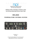
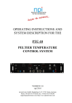
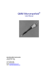
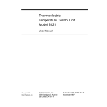
HCT-10 Temperature Controller User Manual June 2012 ALA Scientific Instruments Inc. 60 Marine Street Farmingdale, NY 11735 Voice: 631.393.6401 FAX: 631.393.6407 E-mail: [email protected] www.alascience.com Table of Contents: Page # INTRODUCTION ............................................................................................................. 3 Front Panel ................................................................................................................. 4 Rear Panel .................................................................................................................. 5 SETUP ............................................................................................................................ 5 FEATURES ..................................................................................................................... 7 Changing temperature ................................................................................................ 7 Heating/Cooling feature .......................................................................................... 7 Speed Feature ........................................................................................................ 8 Voltage Feature ...................................................................................................... 9 Set Feature ............................................................................................................. 9 Control Points ....................................................................................................... 10 EXTERNAL TEMPERATURE INPUT ........................................................................... 11 ERROR MESSAGES (ALARMS) ................................................................................. 11 SPECIFICATIONS ........................................................................................................ 12 USAGE EXAMPLES ..................................................................................................... 13 Introduction The HCT temperature controller was specifically designed for the demanding needs of the laboratory. Specifically built for use in electrophysiology it has features that make it a must for all types of labs where precision control of heated and/or cooled small apparatus is necessary. The HCT is a single channel controller in that it can control one heating and or cooling circuit. The system is designed to use two 2252 ohm thermistors. One thermistor is used to monitor the heating or cooling block (the component that does the heating or cooling itself), and the other sensor can be placed in the specimen. For example: The A sensor is built into the ALA HCPC (Heated/cooled perfusion cube) and the B sensor is placed in the recording bath. The control point for the temperature can be either sensor. A unique feature of the HCT is that it can sense if the B sensor has been removed from the bath chamber, or if the chamber has run dry. If that happens, the control point will automatically switch to the A sensor located within the heating/cooling block, and the block will not over heat or freeze as would happen if proper closed loop feedback is lost. Thus the specimen as well as the equipment is protected from damage. The HCT features a membrane display and 5 modes of operation which are simply selected with the up and down arrows on the front panel. Power is supplied by a 24V universal power supply. Components that are to be plugged in must have a 9 pin DIN connector. The B thermistor needs a 2mm standard mono jack. Accurate control is achieved via PID control. The HCT allows the user to select three speeds of operation, the slowest will result in the least overshoot of set point, the fastest the most overshoot. In the Alarm Mode, an alarm will sound, and the control point will be switched to the A sensor automatically. Please note that this feature is default off, and must be initiated each time the unit is turned on. Front Panel ‘A’- Display ‘B’- Change between modes ‘C’- Connector for external controller ‘D’- Connector to measure sensor A from an external source ‘E’- Connector to measure sensor B from an external source ‘F’- Option connector for an additional third external sensor ‘G’- Connector for Sensor A ‘H’- Connector for Sensor B Rear Panel ‘A’- Remote power supply input (24VDC) ‘B’- Power switch ‘C’- Internal cooling fan ‘D’- Fuse ‘E’- Grounding plug Setup To turn on the HTC-10, the 24-volt power supply must be plugged into the designated port labeled ‘A’ on the back panel. Once the power supply is plugged in, the switch ‘B’ on the back panel must be switched to the on position. Make sure you have plugged in at least one device into either port marked sensor A or sensor B before turning on, otherwise an alarm will sound and the HCT will not function. On Position A device must be plugged into Sensor A Output or the Alarm will sound. Upon power up, the display on the front panel will show: The device plugged into component ‘G’ on the front panel can to begin heat and/or cool. A ‘B’ sensor is optional and is used more for reading the temperature in a cell bath or elsewhere. When B is not being used, it will appear as X.X in the channel B reading on the display. High speed, heat, and 2V are the default settings when turned on. The mode and arrow buttons are used to control temperature and other features such as speed, output of voltage, and the heat/cooling feature. Data can be collected and temperature can be controlled through an external interface such as a computer. Output A and B will allow you to record data. Control temp. Externally Features Changing temperature When no item is highlighted, the temperature can be changed by using the up and down arrows. This change will be seen in “set”. Whichever device is in control, either A or B, will follow the temperature change in set. Heating/Cooling feature Heating and cooling can be set to just heat, cool, or both. Press mode until the heat is highlighted, as shown below. The default setting is heat. Using the arrows above and below mode, the heating and cooling function can be changed to the desired function. Note: The Heat/Cool feature is only applicable to devices that can either heat or cool. If the device being used only heats or cools, the h/c feature should not be used. Serious damage to your device can occur. Speed Feature The speed of response of the system can be adjusted with three levels. Pressing mode until the speed function with the three bars is highlighted can do this. The default setting is high. The slow setting gives the most accuracy to limit overshoot, the high setting gives the fastest response, but the most overshoot. Using the arrow keys above and below the mode can change the speed. The three speed functions are low, medium, and high. Set to medium Set to low Voltage Feature The maximum voltage that is output to the heated/cooled device can be changed by pressing mode until the ‘out’ is highlighted, and then using the arrow keys, the voltage can be altered. The voltage ranges from 2 to 12 Volts. Be aware of the maximum voltage your device can tolerate. Read the specifications of the devices being used and do not exceed the maximum voltage due to possible damage. For best results, heating and cooling, this setting should be set on the maximum voltage your device can handle. Set Feature To change the set point temperature, press mode until the set is highlighted. The system always defaults to “set’ mode. To change to external mode, press the arrows until it reads “EX”. Changing the set feature to ‘EX’, or external, means that by plugging in an external source such as a data acquisition system, you can control the set temperature from that external device instead of the HCT itself. The external device should be connected to the port labeled “COMMAND”. Each movement of 10mV will shift the control point 1°C. For best results set the rate of change to within the speed of response of your device. Control Points Feedback for temperature control can come from either sensor A or sensor B. It can also come from an external input (EXT SENSOR). To change the function, press mode until both A and B are highlighted, and then use the arrows to change the input source. Note that if Channel B is not being used (nothing is plugged in) then the B control will not work, and will appear as X.X°C, as seen below: Temperature is not only controlled for A but can be controlled for B as well when B is put in control mode. Once in control mode, you can change the temperature for B by using the arrows when no option is highlighted. ACM Mode: When B is selected as control point, the system is automatically set into ACM mode or Automatic Control Mode. This mode is designed to protect your sample and equipment from overheating or freezing. Since the B sensor is primarily used for measuring temperature in you cell bath, there is the possibility that it can fall out of the bath or that the bath can dry up, thus losing your feedback link with the set-up. This could cause your system to overheat as it tries to heat a dry bath and the sensor keeps reporting only room temperature. If the temperature difference between A and B is more than 7°C the system will sound and alarm and automatically switch control from B, at the B set point level back to Sensor A, which is usually mounted within the heated/cooled device and has assured feedback. External Temperature Input Temperature can also be read by an external source such as a computer or data acquisition system. By plugging into one of the designated ports for either A or B, and then switching the function to external control, data will no longer be displayed on the display but on the external interface that you are using. Error Messages (Alarms) An alarm will sound when the set point is set too high or too low. The range for the set point is from 0°C to 65°C. If the set point is set above or below this range, an alarm will sound and a message saying “over” will display on the screen. An alarm will sound when no device is plugged into either Sensor Ports. Once plugged in however, the alarm will turn off An alarm will sound when the mode for ‘set’ (set point) has been changed to external, and no external device has been plugged in. An alarm will sound if B has been put as control and there is no device plugged into the port for sensor B. An alarm will sound in ACM mode if the difference in temperature between A and B is greater than 7°C. The Alarm will stop after 10 seconds when the control point has been shifted to A automatically. Specifications Dimensions 8.50”L x 7.50”W x 3.75”H Weight 3.20 Lbs Max Voltage Output 12V Voltage Input 24V Max Amp Output 2A Amp Input 4A Sensor Type 2252 Thermistor Usage Examples Operating the HPC, Heated Perfusion Cube The heated Perfusion Cube (HPC) from ALA is a device for heating up a perfusion flow to a cell bath. It is typically used for a flow rate of up to 5ml/min and it is best at between 1 and 3ml/min. Suppose you want it to heat a 2ml/min flow into a 36°C 1.5ml cell bath. When the unit is powered on, heat and high speed will be the default settings. Do not adjust the set point until all features are adjusted to the desired settings. The instrument will respond as soon as the temperature is changed. To change output voltage, hit mode until out is highlighted, then use the arrows to change the voltage. The HPC works best at 12V. To change channel B to read a temperature: hit mode until the A and B Channels are highlighted, and then use the arrows. Once all the desired functions are set, make sure no function is highlighted and use the arrows to change the set point to the desired temperature. In this case the set-point temperature is 36°C. Using The Heat Cool Feature Certain devices can both heat and cool, like ALA’s Heating/Cooling MicroIncubation System (HCMIS). To set up the heat cool feature, plug in the device and turn the machine on. Then, press mode until the heat section is highlighted (heat is default). Press the arrows to change it from heat, cool, and H/C (heat cool). The heat cool feature is designed for keeping the cell bath around room temperature. To lower the temperature past room temperature of about - 5°C or more, use the cool feature, not H/C. Also, if the temperature oscillates too much, the speed may be too fast. If so, adjust the speed by pressing mode until speed is highlighted and use the arrows to adjust speed. When using a device like ALA’s Heated Cooled Perfusion Cube (HCPC) the maximum voltage will need to be set to 7V otherwise damage can occur to the thermoelectric module. Be sure to check the max voltage whenever using thermoelectrics as these are usually lower than heat-only devices with resistive heaters. Also, be sure your thermo-electric device has adequate heat sink to remove heat generated during cooling. (i.e. make sure water or coolant is flowing through the heat sink.) Warranty ALA Scientific Instruments, Inc. agrees to warranty this product against defects in material and workmanship for one year from date of shipment. Remedy shall be limited to replacement or repair of the item(s) at ALA’s discretion. The usage of this product by the user will indicate the users understanding of the use of this product as set forth in this manual. Neither ALA Scientific Instruments, Inc., nor any of its affiliates will be held responsible for damage to laboratory equipment, including microscopes, resulting from the use or misuse of this product, including damage resulting from inputs exceeding specified limits that result in malfunction. This warranty does not cover corrosion or failure of this device due to oxidation of wetted materials resulting from use. In the event that instrument repairs are necessary, shipping charges to the factory are the customer's responsibility. Return charges will be paid by ALA Scientific Instruments. This instrument is not for clinical use. It is strictly for basic research in a laboratory setting. It has no clinical application whatsoever and cannot be used on human subjects.