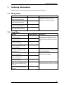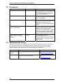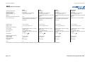
1
8-Channel Miniature Preamplifier
User Manual
Information in this document is subject to change without notice.
No part of this document may be reproduced or transmitted without the express written
permission of Multi Channel Systems MCS GmbH.
While every precaution has been taken in the preparation of this document, the publisher
and the author assume no responsibility for errors or omissions, or for damages resulting
from the use of information contained in this document or from the use of programs and
source code that may accompany it. In no event shall the publisher and the author be liable
for any loss of profit or any other commercial damage caused or alleged to have been
caused directly or indirectly by this document.
© 2002–2006 Multi Channel Systems MCS GmbH. All rights reserved.
Printed: 2006-02-06
Multi Channel Systems
MCS GmbH
Aspenhaustraße 21
72770 Reutlingen
Germany
Fon
+49-71 21-90 92 5 - 0
Fax
+49-71 21-90 92 5 -11
[email protected]
www.multichannelsystems.com
Table of Contents
1
Important Information and Instruction
1
1.1
Operator's Obligations
1
1.2
Guaranty and Liability
1
1.3
Important Safety Advice
2
2
Welcome to the MPA8I
3
3
Setting Up and Connecting the MPA
4
3.1
General Setup Recommendations
4
3.2
Connecting Michigan Probes
5
3.3
Connecting 8-Trodes
9
3.4
Testing the Noise Level of the Setup
5
3.4.1 Setting up MC_Rack
6
3.4.2 Typical Results
7
4
Service and Maintenance
11
4.1
Cleaning the Connectors
11
4.2
Sterilization
11
5
Pin Layout
12
5.1
Power Supply
12
5.2
Input Connector
12
5.3
Output Connector (Male, Front View)
12
5.4
Test Model Probe
13
6
Contact Information
14
7
Ordering Information
15
7.1
ME Systems
15
7.2
Amplifiers
15
7.3
Accessories
16
7.4
Multielectrode Arrays
16
7
Technical Specifications
Important Information and Instruction
1
Important Information and Instruction
1.1
Operator's Obligations
The operator is obliged to allow only persons to work on the device, who
•
are familiar with the safety at work and accident prevention regulations and have been
instructed how to use the device;
•
are professionally qualified or have specialist knowledge and training and have received
instruction in the use of the device;
•
have read and understood the chapter on safety and the warning instructions in this
manual and confirmed this with their signature.
It must be monitored at regular intervals that the operating personnel are working safely.
Personnel still undergoing training may only work on the device under the supervision of an
experienced person.
1.2
Guaranty and Liability
The General conditions of sale and delivery of Multi Channel Systems MCS GmbH always
apply. The operator will receive these no later than on conclusion of the contract.
Multi Channel Systems MCS GmbH makes no guaranty as to the accuracy of any and all tests
and data generated by the use of the device or the software. It is up to the user to use good
laboratory practice to establish the validity of his findings.
Guaranty and liability claims in the event of injury or material damage are excluded when
they are the result of one of the following.
•
Improper use of the device
•
Improper installation, commissioning, operation or maintenance of the device
•
Operating the device when the safety and protective devices are defective and/or
inoperable
•
Non-observance of the instructions in the manual with regard to transport, storage,
installation, commissioning, operation or maintenance of the device
•
Unauthorized structural alterations to the device
•
Unauthorized modifications to the system settings
•
Inadequate monitoring of device components subject to wear
•
Improperly executed and unauthorized repairs
•
Unauthorized opening of the device or its components
•
Catastrophic events due to the effect of foreign bodies or acts of God
1
8-Channel Miniature Preamplifier User Manual
1.3
Important Safety Advice
Warning: Make sure to read the following advices prior to install or to use the device and
the software. If you do not fulfill all requirements stated below, this may lead to
malfunctions or breakage of connected hardware, or even fatal injuries.
Warning: Obey always the rules of local regulations and laws. Only qualified personnel
should be allowed to perform laboratory work. Work according to good laboratory practice
to obtain best results and to minimize risks.
The product has been built to the state of the art and in accordance with recognized safety
engineering rules. The device may only
•
be used for its intended purpose;
•
be used when in a perfect condition.
•
Improper use could lead to serious, even fatal injuries to the user or third parties and
damage to the device itself or other material damage.
Warning: The device and the software are not intended for medical uses and must not be
used on humans.
•
Malfunctions which could impair safety should be rectified immediately.
•
Any physical damage of the cable, such as a broken cable, causes a physical damage of the
miniature preamplifier that cannot be repaired.
•
Protect the device from heat. Do not autoclave!
•
You can clean the connectors with distilled water in an ultra sonic bath, but keep the cable
away from the fluid. Dry the device with compressed air.
•
Use and keep the device always in a dry environment. Do not expose it to fluids or vapor for
a longer period of time.
2
Welcome to the MPA8I
2
Welcome to the MPA8I
The 8-Channel Miniature Preamplifier MPA8I is connected to the microelectrodes for
providing the initial tenfold amplification stage.
It has additional common ground and reference electrode inputs. The reference
electrode is ideally identical to the recording electrodes and placed into a comparable but
inactive area or tissue. Background or noise signals that are picked up by both the reference
electrode and the recording electrodes are removed.
The metal case provides electrical shielding. Electrode damage is prevented by the very
low bias current. The high input impedance ensures stable long-term recordings:
Ideally, the input impedance would be infinite. As low voltages are generally recorded, a
high current would flow if the input impedance were low. As a result, the amplifier would
not be able to deliver the current, and the voltage would break down. The miniature
preamplifier has a high input impedance to avoid this problem.
Adapters for all standard microelectrodes such as Michigan probes (from the Center for
Neural Communication Technology, University of Michigan) or the 8-Trode (from ALA
Scientific Instruments Inc., New York) for acute and chronic implantations ensure a close
proximity to the probe to minimize signal loss and cross talk. Adapters are not included in
the standard scope of delivery and have to be ordered separately. For custom adapters,
please ask your local retailer or contact Multi Channel Systems.
3
8-Channel Miniature Preamplifier User Manual
3
Setting Up and Connecting the MPA
3.1
General Setup Recommendations
In the following, you find general recommendations for the installation. If you are using
Michigan probe or 8-Trode adapters available from MCS, please refer to the following
chapters for more information.
Important: It is important that the complete setup refers to a single common ground.
The reference input has always to be connected. It is recommended to use a reference
electrode. However, if you are not using a reference electrode, connect the reference input
to ground (GND). Otherwise, noise picked up by the reference input will be subtracted from
the recording signals. This will either lead to signal loss or to a very high noise level.
1. Ground the animal with a ground electrode of large surface area, for example, a liquid
gel adhesive electrode, that is connected to the ground of the setup, for example, a
large metal table or a Faraday cage, to avoid pickup of noise from the environment. The
ground electrode is best positioned in an electrically inactive region (not near muscle, nor
heart), for example, at the belly.
2. Connect the GND input or the metal case of the miniature preamplifier to the common
ground of the setup. (The GND input is internally connected to the metal case.)
3. Connect the reference electrode to the reference input of the miniature preamplifier.
Generally, a reference electrode is inserted into non-active tissue of the experimental
model. The reference electrode should be identical to the recording electrode so that both
electrodes see the same background noise. This is necessary because despite the grounding,
the animal’s body often has not exactly a potential of zero, due to the electrode impedance,
for example. The background noise is then subtracted from the recording signal, increasing
the signal to noise ratio. Please note that this may not work if the complete setup is not
properly grounded.
4. Connect the recording electrodes to the recording channels of the miniature
preamplifier. You can either use single electrodes or multitrodes with the miniature
preamplifier. MCS provides adapters for standard probes.
5. Connect all unused recording channels to the REF input or to the reference electrode
(or to the amplifier’s ground if that is not possible) to avoid noise pickup. As the total
amplifier gain generally lies in the range of 1000, even very small noise signals may
generate high noise signals.
4
Setting Up and Connecting the MPA
6. If you are not using a Faraday cage, it might be necessary to shield the complete setup with
aluminum foil or similar to prevent electrical interference from the outside. Connect the
aluminum foil to the ground of the setup (for example, the metal table).
Troubleshooting: If you observe problems with noise, check that the ground of the setup is
connected to exactly the same ground as the data acquisition computer. For example,
connect the metal table to the ground/earth wire of a free power outlet (of the same
electrical system), as the computer is generally connected to ground/earth via the power
plug, too. Also, connect the data acquisition computer’s metal case with a thick
ground wire to the ground of the setup (for example, the metal table), preferably with a
4 mm plug.
3.2
Testing the Noise Level of the Setup
A termination plug that connects all inputs to ground,
and a model test probe that mimics the electrode
impedance are provided for testing the noise level of the
setup.Please note that all instruments were thoroughly
tested at the factory site before delivery. The suggested
tests are mainly intended for optimizing and
troubleshooting your setup, to exclude any damage that
might have occurred during transportation, or to fulfill
your own guidelines, for instance. It will take only a few
minutes time and can save you time and trouble in the
long run. Multi Channel Systems recommends running
these tests before you start your real experiments.
1. Connect the termination plug to one MPA8I, and the model test probe to the other as
shown in the picture (do not mismatch the polarity). If you have only one MPA8I, you can
perform the two tests consecutively.
2. Connect the MPA8I with test model probe to channels 1–8 of the signal collector.
3. Connect the MPA8I with termination plug to channels 9–16 of the signal collector.
4. Make sure that all other connections are appropriate, and that your setup has an
appropriate grounding and shielding as recommended in the chapter General Setup
Recommendations.
5
8-Channel Miniature Preamplifier User Manual
3.2.1 Setting up MC_Rack
Please refer to the MC_Rack User Manual for more information.
1. Start MC_Rack.
2. Open the file MPA8I_NoiseTest.rck on the installation volume (see folder Tutorial). This
rack contains the virtual MC_Card instrument with a continuous raw data display and an
Analyzer to measure the peak-to-peak amplitude.
3. Click Start to start the recording.
— OR — Set up the rack on your own:
1. Click Set Channel Layout on the Edit menu. Select a 1-dimensional layout. Select the
number of electrode channels (at least 16).
2. Add the MC_Card to your virtual rack.
3. In the tree view pane of the virtual rack, select the MC_Card, and click the Hardware tab.
Enter the total amplifier gain according to the specifications of the instruments. For
example, for a miniature preamplifier with a gain of 10 and a following filter amplifier with
a gain of 100, the total gain is 1000.
4. Select an input voltage range of –819.2–818.8 mV and a sampling rate of 10000 Hz.
5. On the Edit menu, click Add Data Display to add a raw data display to your virtual rack.
5. In the virtual rack tree view pane, select the Display 1 and click the Layout tabbed page.
Set up a channel map with channels 1–16.
6. Adjust the display ranges to 500 ms and +/–50 µV.
7. On the Edit menu, click Add Analyzer to add an Analyzer to the virtual rack. Select all or
two typical channels on the Channels tabbed page. Select the Peak-Peak Amplitude
parameter on the Analyzer tabbed page.
8. On the Edit menu, click Add Parameter Display to add a Parameter Display to the
virtual rack.
9. In the virtual rack tree view, select the Display 2 and click the Layout tabbed page. Set up
a channel map with all channels that were assigned to the Analyzer.
10. Click the Ranges tabbed page and enter 0–10 s for the x range and 0–100 µV for the
y range.
6
Setting Up and Connecting the MPA
3.2.2 Typical Results
Typical results of this test are shown in the following screen shot. The filter amplifier used
for this test had a gain of 100 and a bandwidth of 0.5–5000 Hz (FA64I-100-0.5-5000). If you
use a filter amplifier with a narrower bandwidth, you can generally expect a slightly lower
noise level.
Figure 1 Noise level test with MPA8I and FA64I-100-0.5-5000 filter amplifier.
The noise level is 60 µV peak to peak with the provided test model probe (channels 1–8) and
20 µV peak to peak with grounded inputs (channels 9–16). The top window shows raw data;
the bottom window shows the extracted peak-to-peak amplitudes of channels 1 and 9. (The
miniature preamplifier was shielded by a metal case connected to the ground/earth of the
test lab.)
7
8-Channel Miniature Preamplifier User Manual
3.3
Connecting Michigan Probes
→ Insert one pin array of the Michigan Probe adapter into one MPA8I, and the other into the
second MPA8I. Make sure that the orientation of the MPA8I is correct (see illustration).
The adapter’s ground input and reference input have been connected as factory-default
settings. You can change this connection to meet your requirements, but make sure that the
reference input is not open.
8
Setting Up and Connecting the MPA
3.4
Connecting 8-Trodes
The 8-Trode adapter allows a direct connection of the 8-Trode (from ALA Scientific
Instruments Inc., New York) for acute and chronic implantations to an 8-channel miniature
preamplifier (MPA8I).
→ Connect the 8-Trode adapter to the miniature preamplifier on one side and to the 8-Trode
on the other side.
9
8-Channel Miniature Preamplifier User Manual
The MPA8I has two ground inputs. The two ground outputs of the 8-Trode-adapter are only
required for connecting these two inputs to the ground of the adapter, they have no
additional function.
There is an optional 0 Ohm resistor that can be connected between the reference (R)
input and output. If this is not the case (the standard state of delivery), the input is
measured against the input of the R pin, that is, the noise measured with the R electrode is
subtracted from the input signals of the 8 channels.
It is possible to solder a 0 Ohm resistor onto the adapter. In this case, the reference input
will be connected to ground, that is, all signals would be measured against the general
ground of the setup. Please specify this option on your order.
10
Service and Maintenance
4
Service and Maintenance
4.1
Cleaning the Connectors
Warning: Make sure that only the connectors touch the liquid; do not submerge the
miniature preamplifier or the cable into cleaning solutions. Otherwise, you can fatally
damage the electronics. It is recommended to avoid the use of aqueous cleaning solutions to
avoid corrosion. If necessary, use distilled water.
→ Clean the connectors with 70 % alcohol and cotton swabs from time to time.
→ If this does not provide satisfying results, insert only the connectors into a small beaker with
acetone or alcohol and sonificate for 10–20 s in an ultrasonic bath. Air-dry the miniature
preamplifier for about 5 min before use.
→ You can clean the connectors with distilled water in an ultra sonic bath. Dry the connectors
with compressed air immediately after sonification and let the amplifier air dry for at least
6 h before use.
4.2
Sterilization
Warning: Do not autoclave or sterilize miniature preamplifiers by high heat (above 70 °C)
or vapor. The resin is not heat-stable and may deform under heat. Vapor can lead to a
corrosion of the electronics.
Miniature preamplifiers can be sterilized with standard methods that are not based on high
heat or vapor, for example, with 70 % ethanol, UV-light, or by thermal sterilization in an
oven at 56 °C with an incubation time of 8 hours.
11
8-Channel Miniature Preamplifier User Manual
5
Pin Layout
5.1
Power Supply
Supply voltage is applied to the output connector pins 8 and 15. The voltage source should
supply a stable noise-free voltage. Do not exceed the maximum voltage.
Pin 8: –3 V to –8 V
Pin 15: +3 V to +8 V
Warning: Do not mismatch the polarity of the power supply. A false connection may
damage the unit.
5.2
Input Connector
Please note that the black side is considered the top side.
1
Ground (GND)
2
Reference input
3 ... 10
Recording channels 1 to 8
11
5.3
Ground (GND)
Output Connector
1
3
2
9
10
4
11
Connector
5
6
13
12
Cable
7
14
8
15
Output
1
1
Ground (GND)
9
2
Signal ground*
2, 10, 3, 11, 4, 12, 5, 13
3 ... 10
Recording channels 1—8
6, 14, 7
11 ... 13
Ground (GND)
15
14
Positive supply voltage
8
15
Negative supply voltage
* = Connected to the ground of the amplifier. The signal ground is used as the reference for
the following filter amplifier.
12
Pin Layout
5.4
Test Model Probe
Test signal IN: You can use the jumper to connect the signal input pin (Signal IN) to
ground (standard situation for a noise level test), or you can connect a data source, for
example, a sine wave generator to the input (and the ground of the test signal to the signal
ground input) to test the signal distribution. The input signal is distributed across all
recording channels.
REF IN: The standard situation in an experiment should be that the reference electrode has
properties identical or close to the recording electrodes. You can remove the jumper to
connect the reference output of the test model probe to the same resistors as the recording
channels to mimic the experimental situation, or you can use the jumper to connect the
reference output to ground.
DC resistance
Dynamic resistance
Capacitance
4.7 MOhm
330 kohm
150 pF
13
8-Channel Miniature Preamplifier User Manual
6
Contact Information
Local retailer
Please see the list of official MCS distributors on the MCS web site.
User forum
The Multi Channel Systems User Forum provides an excellent opportunity for you to
exchange your experience or thoughts with other users worldwide.
Mailing list
If you have subscribed to the ME-System mailing list, you will be automatically informed
about new software releases, upcoming events, and other news on the product line. You
can subscribe to the list on the MCS web site.
www.multichannelsystems.com
14
Ordering Information
7
Ordering Information
Please contact your local retailer for pricing and ordering information.
7.1
7.2
ME Systems
Product
Product Number
Description
Data acquisition system
with 16 analog channels
ME16 System
Data acquisition system
with 32 analog channels
ME32 System
Complete with data acquisition
computer with MC_Card and
IPS10W, and software package
Data acquisition system
with 64 analog channels
ME64 System
Data acquisition system
with 128 analog channels
ME128 System
Amplifiers
Product
Product Number
Description
Miniature preamplifier with 2
electrode inputs
MPA2I
Miniature preamplifier with 8
electrode inputs
MPA8I
Small sized and light weight
headstage with common ground
and additional indifferent reference
electrode input, input type I, gain =
10
Miniature preamplifier with
32 electrode inputs
MPA32I
Miniature preamplifier with
32 electrode inputs for use
with FlexMEAs
MPA32IFLEX
Filter amplifiers with 4, 8, 16,
32, 48, or 64 channels and
input type S or I
FANNX
NN is the total number of channels, X
is the input type (S or I), with custom
gain and bandwidth
Amplifier with programmable
gain, 16 channels
PGA16
Gain programmable from 10 to 5000,
with custom bandwidth
Amplifier with programmable
gain, 32 channels
PGA32
Amplifier with programmable
gain, 64 channels
PGA64
Amplifier with programmable
gain, 16 input and 32 output
channels
PGA1632
Amplifier with programmable
gain, 32 input and 64 output
channels
PGA3264
Gain programmable from 10 to 5000,
with two different custom pass bands
15
8-Channel Miniature Preamplifier User Manual
7.3
7.4
Accessories
Product
Product Number
Description
Michigan Probe adapters
MP-ADPT-16
Allow a direct connection of
Michigan probes to two miniature
preamplifiers MPA8I. Available for
16, 32, and 64 channels.
8-Trode adapter
8-Trode adapter
Allows a direct connection of the 8Trode from ALA Scientic Instruments
Inc. to the MPA8I.
Signal collector for 8 x MPA8I
SC8x8
Collects the 8 channels from each of
the up to 8 miniature preamplifiers
MPA8I and leads them to the
amplifier via a 68-pin MCS standard
cable
Signal collector with blanking
circuit for 8 x MPA8I
SC8x8BC
Collects the 8 channels from each of
the up to 8 miniature preamplifiers
MPA8I and leads them to the
amplifier via a 68-pin MCS standard
cable, the voltage outputs are held
constant during the TTL blanking
signal, stimulus artifacts are avoided
Power supply with 20 W
power and +/– 7 V output
voltage
PS20W
For supplying power to
programmable gain amplifiers, for
custom setups that lack an internal
power supply, or for other custom
applications
Multielectrode Arrays
Multielectrode arrays are not available from Multi Channel Systems, but from several other
providers. The following are compatible with the miniature preamplifiers from Multi
Channel Systems. If you are interested in a particular probe that is not mentioned here,
please ask Multi Channel Systems or your local retailer for compatibility.
Product
Description
Michigan
probes
16-channel silicon probes
NeuroNexus Technologies
www.neuronexustech.com
8-Trode
Electrodes with eight pads, for in vivo
acute or chronic implantation
ALA Scientific Instruments,
Inc.
www.alascience.com
16
Supplier
Technical Specifications
Date of Print: 23.11.2005
MPA Miniature Preamplifier
MPA8I
0 °C to 50 °C
0 °C to 50 °C
10 % to 85 %, non-condensing
17 mm x 25 mm x 1.8 mm
1.3 g w/o cable and plug, 21 g with cable
and plug
2 kg
2 kg
Single-row precision sockets, 50 mil (1.27 Single-row precision sockets, 50 mil (1.27
mm) grid pattern, for 0.35-0.45 mm
mm) grid pattern, for 0.35-0.45 mm
round pins)
round pins)
MPA32I
0 °C to 50 °C
0 °C to 50 °C
10 % to 85 %, non-condensing
27 mm x 36 mm x 5 mm
7 g w/o cable and plug, 56 g with cable
and plug
2 kg
Dual-row precision sockets, 50 mil (1.27
mm) grid pattern, for 0.35-0.45 mm
round pins)
MPA32IFLEX
0 °C to 50 °C
0 °C to 50 °C
10 % to 85 %, non-condensing
27 mm x 34 mm x 5 mm
7 g w/o cable and plug, 56 g with cable
and plug
2 kg
Special input for use with FlexMEAs
Supply voltage
Supply current
± 3 V to ± 8 V DC
< ± 2 mA, typically ± 1 mA
± 3 V to ± 8 V DC
< ± 6 mA, typically ± 4 mA
± 3 V to ± 8 V DC
< ± 14 mA, typically ± 9 mA
± 3 V to ± 8 V DC
< ± 14 mA, typically ± 9 mA
Number of input channels
Input voltage
Noise density
2
0 to 500 mV (with respect to a supply
voltage of 5 V)
1012 Ω parallel to 10 pF
< 1.5 µV RMS (1 Hz to 5 kHz, inputs shortcircuited)
en = 15 nV / Hz
8
0 to 500 mV (with respect to a supply
voltage of 5 V)
1012 Ω parallel to 10 pF
< 1.5 µV RMS (1 Hz to 5 kHz, inputs shortcircuited)
en = 15 nV / Hz
32
0 to 500 mV (with respect to a supply
voltage of 5 V)
1012 Ω parallel to 10 pF
< 1.5 µV RMS (1 Hz to 5 kHz, inputs shortcircuited)
en = 15 nV / Hz
32
0 to 500 mV (with respect to a supply
voltage of 5 V)
1012 Ω parallel to 10 pF
< 1.5 µV RMS (1 Hz to 5 kHz, inputs shortcircuited)
en = 15 nV / Hz
Number of output channels
Output voltage
Output current
Output impedance
Bandwidth
2
= supply voltage
max ± 10 mA
0Ω
DC to 50 kHz
8
= supply voltage
max ± 10 mA
0Ω
DC to 50 kHz
32
= supply voltage
max ± 10 mA
0Ω
DC to 50 kHz
32
= supply voltage
max ± 10 mA
0Ω
DC to 50 kHz
Gain
10
10
10
10
Operating temperature
Storage temperature
Relative humidity
Dimensions (W x D x H)
Weight
Maximum tensile strength of cable
Input connector type
Input impedance
Input noise
MPA2I
0 °C to 50 °C
0 °C to 50 °C
10 % to 85 %, non-condensing
12 mm x 31 mm x 3 mm
Versions with 2, 8 and 32 channels available, MPA2I, MPA8I, and MPA32I, respectively. MPA 32IFLEX is a special version for use with Flex-MEAs.
Page 1 of 1
© 2003 Multi Channel Systems MCS GmbH