1
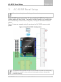
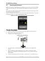
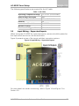
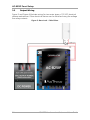
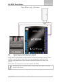
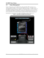
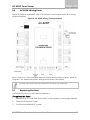
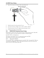
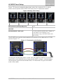
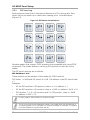
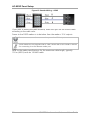
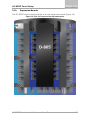
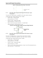
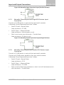
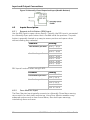
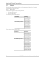
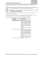
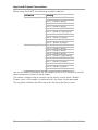
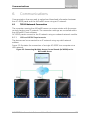
AC-825IP Networked Controller Hardware Installation and User Guide Copyright © 2015 by Rosslare. All rights reserved. This manual and the information contained herein are proprietary to ROSSLARE ENTERPRISES LIMITED and/or its related companies and/or subsidiaries’ (hereafter: "ROSSLARE"). Only ROSSLARE and its customers have the right to use the information. No part of this manual may be re-produced or transmitted in any form or by any means, electronic or mechanical, for any purpose, without the express written permission of ROSSLARE. ROSSLARE owns patents and patent applications, trademarks, copyrights, or other intellectual property rights covering the subject matter in this manual. TEXTS, IMAGES, AND ILLUSTRATIONS INCLUDING THEIR ARRANGEMENT IN THIS DOCUMENT ARE SUBJECT TO THE PROTECTION OF COPYRIGHT LAWS AND OTHER LEGAL RIGHTS WORLDWIDE. THEIR USE, REPRODUCTION, AND TRANSMITTAL TO THIRD PARTIES WITHOUT EXPRESS WRITTEN PERMISSION MAY RESULT IN LEGAL PROCEEDINGS. The furnishing of this manual to any party does not give that party or any third party any license to these patents, trademarks, copyrights or other intellectual property rights, except as expressly provided in any written agreement of ROSSLARE. ROSSLARE reserves the right to revise and change this document at any time, without being obliged to announce such revisions or changes beforehand or after the fact. Table of Contents Table of Contents 1. Introduction ....................................................................... 8 1.1 Features.............................................................................................. 9 1.2 AxTraxNG ......................................................................................... 10 1.3 Compatible Readers .......................................................................... 10 2. Technical Specifications ................................................. 11 2.1 AC-825IP Enclosures (ME-1525 and ME-1505) .................................. 11 2.2 Expansions for AC-825IP ................................................................... 12 3. AC-825IP Panel Setup ...................................................... 13 3.1 Powering the Enclosure..................................................................... 14 3.2 Input Wiring – Supervised Inputs ....................................................... 15 3.3 Output Wiring .................................................................................. 16 3.4 Open Supervised Device Protocol ...................................................... 17 3.5 Power Management ......................................................................... 18 3.6 AC-825IP Wiring Ports ...................................................................... 19 3.7 Replacing the Fuse ............................................................................ 19 3.8 R/S/D/P-805 Extension Board Setup ................................................... 20 3.9 Readers and Cable Length ................................................................ 23 3.10 Expansion Boards.............................................................................. 25 4. Input and Output Connections ...................................... 27 4.1 Input Types ....................................................................................... 27 4.2 Inputs Description ............................................................................. 30 4.3 Outputs ............................................................................................ 32 4.4 Card Readers and Keypads................................................................ 33 5. AC-825IP Hardware Settings .......................................... 35 5.1 DIP Switch Configuration .................................................................. 38 5.2 Setting AC-825IP Panel Type in AxTraxNG ......................................... 38 AC-825IP Hardware Installation and User Guide iii Table of Contents 6. Communications ............................................................. 39 6.1 TCP/IP Network Connection .............................................................. 39 A. Limited Warranty ............................................................ 41 iv AC-825IP Hardware Installation and User Guide List of Figures List of Figures Figure 1: Sample AC-825IP Configuration..................................................... 13 Figure 2: Location of the Maximum Power Rating Sticker .............................. 14 Figure 3: AC Power Wiring ........................................................................... 14 Figure 4: Input Wiring – Supervised Inputs .................................................... 15 Figure 5: Door Lock – Failed Close ................................................................ 16 Figure 6: Door Lock – Failed Open ................................................................ 17 Figure 7: AC-825IP in the ME-1525 Enclosure............................................... 18 Figure 8: AC-825IP Wiring Communications ................................................. 19 Figure 9: Fuse Cover ..................................................................................... 20 Figure 10: Daisy Chain Setup ........................................................................ 21 Figure 11: Termination with Resistor ............................................................. 21 Figure 12: DIP Switch Combinations ............................................................. 22 Figure 13: Connection using RS-485 Connectors .......................................... 23 Figure 14: Reader Wiring – Wiegand ............................................................ 23 Figure 15: Reader Wiring – OSDP ................................................................. 24 Figure 16: Slot for Expansion Board Attachment ........................................... 25 Figure 17: Normally Open Input Connection ................................................. 27 Figure 18: Normally Closed Input Connection ............................................... 28 Figure 19: Normally Open Supervised Input (Single Resistor).......................... 28 Figure 20: Normally Open Supervised Input (Double Resistor) ........................ 29 Figure 21: Normally Closed Supervised Input (Single Resistor)........................ 29 Figure 22: Normally Closed Supervised Input (Double Resistor) ...................... 30 Figure 23: Connecting Multiple Access Control Panels (AC-825IP) to the AxTraxNG Server ......................................................................... 39 AC-825IP Hardware Installation and User Guide v List of Tables List of Tables Table 1: AC Cable ........................................................................................ 15 Table 2: Possible Hardware Settings .............................................................. 35 vi AC-825IP Hardware Installation and User Guide Notice and Disclaimer Notice and Disclaimer This manual’s sole purpose is to assist installers and/or users in the safe and efficient installation and usage of the system and/or product, and/or software described herein. BEFORE ATTEMPTING TO INSTALL AND/OR USE THE SYSTEM, THE INSTALLER AND THE USER MUST READ THIS MANUAL AND BECOME FAMILIAR WITH ALL SAFETY REQUIREMENTS AND OPERATING PROCEDURES. The system must not be used for purposes other than those for which it was designed. The use of the software associated with the system and/or product, if applicable, is subject to the terms of the license provided as part of the purchase documents. ROSSLARE ENTERPRISES LIMITED and/or its related companies and/or subsidiaries’ (hereafter: "Rosslare") exclusive warranty and liability is limited to the warranty and liability statement provided in an appendix at the end of this document. This manual describes the maximum configuration of the system with the maximum number of functions, including future options. Therefore, not all functions described in this manual may be available in the specific system and/or product configuration you purchased. Incorrect operation or installation, or failure of the user to effectively maintain the system, relieves the manufacturer (and seller) from all or any responsibility for consequent non-compliance, damage, or injury. The text, images and graphics contained in the manual are for the purpose of illustration and reference only. In no event shall manufacturer be liable for any special, direct, indirect, incidental, consequential, exemplary, or punitive damages (including, without limitation, any and all damages from business interruption, loss of profits or revenue, cost of capital or loss of use of any property or capital or injury). All graphics in this manual are for reference only, some deviation between the image(s) and the actual product may occur. All wiring diagrams are intended for reference only, the photograph or graphic of the PCB(s) are intended for clearer illustration and understanding of the product and may differ from the actual PCB(s). AC-825IP Hardware Installation and User Guide vii Introduction 1. Introduction The AC-825IP is an advanced networked access controller and is the backbone of a medium-scale to high-scale security system that can handle up to 60,000 users and 500,000 events. Each AC-825IP access control unit (ACU) supports up to 6 doors (In/Out), each with 2 inputs and 1 output, and includes four additional auxiliary inputs and two auxiliary outputs. The number of supported doors, inputs, and outputs can be increased by using the onboard 10-pin expansion slot to connect any of the following expansion boards: R-805 – 16 outputs S-805 – 16 inputs D-805 – 4-door expansion P-805 – 16 inputs and 8 outputs The system currently supports 12 extension boards via RS-485 with OSDP, of any kind, in addition to the expansion board mounted on top of the AC-825IP panel. In the future, the system may support up to 16 extension boards. Driven by Rosslare’s powerful, flexible and easy to use AxTraxNG™ software, the system provides an ideal, modular and expandable solution for commercial and institutional needs. It provides seamless integration with Rosslare's range of RFID proximity, PIN, Proximity & PIN, smart card, and biometric readers with Rosslare’s selection of RFID credentials. The AC-825IP is ready for installation with a mountable and lockable metal enclosure (ME-1525) integrated with a switch, power management board/charger, sounder, and control panel. The R/S/D/P-805 expansion boards are ready for installation with a mountable and lockable metal enclosure (ME-1505) integrated with a switch, power management board /charger, sounder, and control panel. Using an onboard Ethernet TCP/IP, multiple local or remote site door subnetworks can connect to the AxTraxNG Client/Server PC software running ® ® on Microsoft Windows 7/8 operating systems. 8 AC-825IP Hardware Installation and User Guide Introduction The AC-825IP platform consists of the following components: AC-825IP networked access controller ME-1525 and ME-1505 metal enclosures with a detachable illumination bar Up to 4 A power management board VAC/VDC power switch Terminal block removal tool 1.1 12 x 2.2 kΩ and 12 x 8.2 kΩ resistors for the supervised inputs Features The AC-825IP is a powerful and adaptable access control solution with a range of powerful features: Controls 6 doors – 4 readers are connected via Wiegand format and 2 are connected via Open Supervised Device Protocol (OSDP) Controls an additional 4 doors connected via Wiegand when an D-805 is mounted (optional) Four IN/OUT readers, with tamper switch and LED control 12 supervised inputs, 28 when the S-805 or the P-805 expansions are installed 6 Form-C relay outputs, 22 when R-805 is installed Onboard TCP/IP communication, incorporated bi-directional push communication with AxTraxNG server for enhanced data transmission speed and reliability Uses an AES 128-bit encryption between the AC-825IP panel and the AxTraxNG server Supports up to 60,000 users Supports up to 500,000 history log entries (FIFO) per ACU Built-in sounder for chime, bell and siren signals Remote firmware upgrades Removable terminal blocks A real-time clock keeps time for up to 2 weeks without power and is backed up by a battery. AC-825IP Hardware Installation and User Guide 9 Introduction 1.2 AxTraxNG The AxTraxNG software is custom designed to set up, manage, and supervise all aspects of an access controller’s network. It offers the following capabilities: 1.2.1 Client-Server Structure AxTraxNG operates through a dedicated AxTraxNG server computer, which communicates with the access control panels and their expansions to serve an unlimited number of network clients. The server also runs the system's SQL database, which contains settings and definitions for access control across the entire facility. System users can define new users and credentials, and control access permissions. The system includes tools for database backup, input, and export of previous configurations and automatic backup on a periodic basis. AxTraxNG supports all panel types and offers scalability and flexibility in addition to a range of advanced control features. 1.2.2 Configurable Links The system's configurable links model makes it possible to trigger any chosen output automatically or report a configurable alarm, based on a selected input. This allows easy integration with other access systems such as intruder alarms, CCTV systems, and License Plate Recognition (LPR). AxTraxNG can also define a selected set of operations, which are defined in configurable links, when a panel registers a specified user or a group of users. This can be useful, for example, in access control systems. The system can assign users with counters, allowing a limited number of entries to each panel. 1.3 Compatible Readers The AC-825IP ACU provides support for most of the Wiegand formats, such as 26-bit, 30-bit, 32-bit, 35-bit, and 36-bit, as well as any OSDP readers that may be connected serially to the AC-825IP via RS-485 interface. 10 AC-825IP Hardware Installation and User Guide Technical Specifications 2. Technical Specifications 2.1 AC-825IP Enclosures (ME-1525 and ME-1505) ELECTRICAL SPECIFICATIONS Enclosure SMPS Input: 100 to 240 VAC, 1.6 A, 50–60 Hz, switch mode power management board Output: 12 VDC, 4 A PCBA Input Power Backup Battery (sold separately) 15 VDC, 2 A, regulated power management board 12 V sealed lead acid (SLA) up to 7 Ah, IEC62133 Relay Outputs 5 A DC, 150 W max. Auxiliary Outputs 12 VDC, 1.2 A typical (1.5 A max.) Fuse 250 V, 2.5 A OPERATIONAL SPECIFICATIONS Relays 5 A, Form-C 6 Supervised Inputs 12 Readers (Wiegand Format) 4 Readers (OSDP Format) 2 Expansion Ports 1 Connectivity TCP/IP, OSDP OPERATIONAL SPECIFICATIONS (AC-825IP only) Capacity Up to 60,000 users History Event Log Size Up to 500,000 entries Time Zones and Groups Special Features with AxTraxNG 256 multi-segment time zones, 64 holidays – each holiday can be multiple days Practically unlimited amount of access groups Interlock, first-person delay, auto-relock, scheduled outputs operation, 4 programmable site codes, extended unlocked time, fully interconnectedness, car parking management, antipassback (per reader, between readers) Security Modes Normal and Secure ENVIRONMENTAL SPECIFICATIONS Operating Temp. Range Storage Temp. Range Operating Humidity Range -5°C to 50°C (23°F to 122°F) -25°C to 50°C (-13°F to 122°F) 0 to 85% (non-condensing) AC-825IP Hardware Installation and User Guide 11 Technical Specifications MECHANICAL SPECIFICATIONS Enclosure Dimensions (H x W x D) 346 x 404 x 101 mm (13.6 x 15.9 x 4.0 in.) Enclosure Weight* 4.6 kg (10.1 lb) PCBA Dimensions (H x W) 224 x 164 mm (8.8 x 6.46 in.) PCBA Weight 400 g (14.1 oz) Backup Battery Dimensions (H x W x D) 95 x 150 x 65 mm (3.7 x 5.9 x 2.6 in.) Fuse Dimensions (H x W) * 20 x 5 mm (0.8 x 0.2 in.) For weight purposes, the ME-1525 and ME-1505 enclosures include the metal box, AC input, DC output and LED bar. 2.2 Expansions for AC-825IP Specification R-805 S-805 D-805 P-805 OPERATIONAL SPECIFICATIONS Relays 5 A, Form-C 16 N/A 4 8 Supervised Inputs N/A 16 8 16 Readers (Wiegand Format) N/A N/A 4 N/A Readers (OSDP Format) N/A N/A N/A N/A Connectivity OSDP ENVIRONMENTAL SPECIFICATIONS Operating Temp. Range -5°C to 50°C (23°F to 122°F) Storage Temp. Range -25°C to 50°C (-13°F to 122°F) Operating Humidity Range 0 to 85% (non-condensing) MECHANICAL SPECIFICATIONS Weight Dimensions (H x W x D) 12 230 g (8.1 oz) 150 g (5.3 oz) 200 g (7.1 oz) 178 x 87 x 30 mm (7.0 x 3.4 x 1.2 in.) AC-825IP Hardware Installation and User Guide AC-825IP Panel Setup 3. AC-825IP Panel Setup The unit should only be installed by a professional service person. Each AC-825IP panel controls 6 or 10 doors (with the D-805) (3 or 5 doors in double reader per door mode). The panels connect together in a network and are controlled by a central server computer, running the AxTraxNG software system. Figure 1 shows an example setup for a network of AC-825IP access control panels. Figure 1: Sample AC-825IP Configuration The highlited area indicates the use of OSDP readers and their I/O connectivity. Bushings are needed for any conductors leaving the enclosure through the provided openings. AC-825IP Hardware Installation and User Guide 13 AC-825IP Panel Setup 3.1 Powering the Enclosure Before wiring the AC-825IP board and expansions, you must first wire the ME1525 enclosure (and ME-1505 enclosure for expansions boards) using an AC cable. The maximum power rating and input allowed is indicated on the cover of the AC terminal inside the enclosure. Figure 2 indicates the location of the maximum power rating sticker. Once you remove the cover, you can find the terminal block. Figure 2: Location of the Maximum Power Rating Sticker To power the enclosure: 1. 2. 3. Locate the box labeled AC power in the left bottom of the enclosure. Remove the screws that hold the box. Connect the AC cable (Figure 3). Figure 3: AC Power Wiring 4. 5. 6. 14 Once the cable is connected properly, close the box and tighten the screws. Place the backup battery between the AC power and the DC power. Make sure the battery is positioned properly so it is secured by the two placeholders. Connect the battery to the DC power – red wire to ‘+’ and black wire to ‘–‘. AC-825IP Hardware Installation and User Guide AC-825IP Panel Setup The following specifications are required for the AC cable: Table 1: AC Cable Operating Temperature Range -5ºC to 70ºC (23ºF to 258ºF) 3.2 Rated Voltage Uo/U (µm) 300 V Conductor Cross-Section 0.75 mm2, 18 AWG Isolation PCV International Standard IEC 60227-5 Number of Cores 3 Recommended Type of Cable H03VV-F 3 G Input Wiring – Supervised Inputs When wiring the AC-825IP for supervised inputs, resistors should be placed on the input switch and not on the terminal block. Figure 4 presents a view of the inputs and their connection options. Figure 4: Input Wiring – Supervised Inputs For more details on reader connectivity, refer to Figure 14 and Figure 15 in Section 3.9. AC-825IP Hardware Installation and User Guide 15 AC-825IP Panel Setup 3.3 Output Wiring Figure 5 and Figure 6 illustrate wiring for two main types of 12 VDC electrical release mechanisms. Other electrical devices can be switched using the voltage free relay contacts. Figure 5: Door Lock – Failed Close 16 AC-825IP Hardware Installation and User Guide AC-825IP Panel Setup Figure 6: Door Lock – Failed Open 3.4 Open Supervised Device Protocol OSDP allows connecting control panels with various peripheral devices (card readers, control panels, and other security management systems) while unlocking the potential of the onboard computing resources within the system. Each panel can connect to up to two readers via OSDP. Any device that is connected to the AC-825IP panel via RS-485 must have a unique serial address. AC-825IP Hardware Installation and User Guide 17 AC-825IP Panel Setup 3.5 Power Management Figure 7 illustrates the AC-825IP ACU within the ME-1525 enclosure. It is recommended to add a 12 VDC lead acid backup battery in case the power management board fails (see Chapter 2). If the main input is 12 VDC, wire it to the power management board, which has a load rating of up to 4 A for lock connectivity (for battery installation instructions, please refer to Section 3.1). If 4 A is not sufficient, an external power supply should be added according to the electrical requirements. For more information, refer to Section 4.3. Figure 7: AC-825IP in the ME-1525 Enclosure 18 AC-825IP Hardware Installation and User Guide AC-825IP Panel Setup 3.6 AC-825IP Wiring Ports Figure 8 presents a detailed view of the access control panel with all it wiring communications. Figure 8: AC-825IP Wiring Communications AUX1 and AUX 2 are additional auxiliary inputs and auxiliary outputs. Refer to Chapter 2 for maximum power ratings and further information. The USB G-Bus ports and DIP switches are currently not functional. 3.7 Replacing the Fuse If a fuse burns out, you will need to replace it. To replace the fuse: 1. 2. Remove the AC cord from the socket, so the system is not being powered. Open the enclosure’s case. 3. Find the box labeled AC power. AC-825IP Hardware Installation and User Guide 19 AC-825IP Panel Setup 4. Open the screws and remove the cover (Figure 9). Figure 9: Fuse Cover 5. 6. 7. 8. Grab the top of the fuse and pull it out. Insert the new fuse. Make sure it clicks in when inserted. Close the cover of the AC power box and screw it shut. Connect the system to the power. 3.8 R/S/D/P-805 Extension Board Setup Each extension board must be located inside an ME-1505 enclosure. Each ME1505 can contain up to two extension boards of different types. Each ME-1505 is self-powered. The system can support up to 12 expansion boards via OSDP. We recommend using a daisy chain connection. 3.8.1 Daisy Chain System The first ME-1505 is connected directly to the ME-1525. All other ME-1505 are connected to another ME-1505 in that way transmission will flow across the chain to the AC-825IP panel and back. 20 AC-825IP Hardware Installation and User Guide AC-825IP Panel Setup Figure 10 shows an example daisy chain setup for a network of AC-825IP access control panels with 6 ME-1505 units and 12 expansion boards. Figure 10: Daisy Chain Setup Max Distance between ME units 1 km Max Distance from ME-1525 to the last ME-1505 1 km Recommended Cable Type STP cat5 (shielded twisted pair category 5). If the cable is not Category 5, we recommend using a 24-AWG cable with 100–120 Ω The RS-485 bus must be terminated at both ends of the cable with a 120 Ω resistor (Figure 11). Figure 11: Termination with Resistor If multi-pair twisted pair cable is used, one pair shall be used for A+ and Bsignals (blue and white/blue) and one pair for GND (orange + white/orange). Unused wires should be terminated with 100 Ω resistors to ground at both ends of the cable. AC-825IP Hardware Installation and User Guide 21 AC-825IP Panel Setup 3.8.2 DIP Switching Each expansion board has 4 switches to determine its ID in the system. Each switch can be set either up or down thus creating up to 16 combinations (Figure 12). Figure 12: DIP Switch Combinations Rosslare readers that support OSDP operation are compatible with most OSDP commands. The reader address is set using DIP switches on the back of the reader. The DIP switch settings are as follows: DIP Switches 1 to 4 These switches set the address of the reader for OSDP protocol. DIP Switch 1 is MSB and DIP Switch 4 is LSB. The address is the DIP switch state +1. Examples: All the DIP switches in Off position, state is = 0 => address = 1 All the DIP switches in On position, state is = 0x0F => address = 0x10 = 16 DIP switches 1, 3, 4 in On position and 2 in Off position, state is = 0x0B => address = 0x0C = 12 In every system, each board’s ID must be unique. The ID is set only in the initialzation phase. The system does not synchronize if an existing board’s ID is changed or if a board is added or removed. The system must be initialized to synchronize the IDs. 22 AC-825IP Hardware Installation and User Guide AC-825IP Panel Setup 3.8.3 Connecting the System via RS-485 Each AC-825IP panel or expansion board has an RS-485 connection designated as A, B, ’-’. When installing the system, note that connector A must be connected with its equivalent and connector B must be connected to a connector B. The connecter ‘-’ is the extension and must be connected accordingly in every one of the boards and panels. If the system’s topology is in the form of a daisy chain, the installer must add a 120 Ω resistor to the final RS-485 connector or panel. Figure 13 shows an example of connecting two expansion boards using the RS-485 connectors A, B and ‘–‘. Figure 13: Connection using RS-485 Connectors 3.9 Readers and Cable Length Readers are supplied with cables having a limited length. The color of the cable cover represents the cable’s functionality according to the Wiegand and OSDP standards (Figure 14 and Figure 15). Figure 14: Reader Wiring – Wiegand AC-825IP Hardware Installation and User Guide 23 AC-825IP Panel Setup Figure 15: Reader Wiring – OSDP If you wish to extend the cable distance, make sure you use the correct cable according to the cable color. Power to the OSDP readers is to be taken from the reader +12 V outputs. Do not connect more than two readers per each +12 V output. Some readers are not supplied with a cable. Please refer to the reader’s manual for connecting it to the relevant reader port. Refer to the reader specifications for the maximum cable length, typically 150 m (492 ft) with an 18 AWG cable. 24 AC-825IP Hardware Installation and User Guide AC-825IP Panel Setup 3.10 Expansion Boards The AC-825IP control panel provides a slot for expansion boards (Figure 16). Figure 16: Slot for Expansion Board Attachment AC-825IP Hardware Installation and User Guide 25 AC-825IP Panel Setup There are four types of expansion boards as follows: R-805 – The R-805 is an optional expansion board that adds 16 outputs to the access control panel. S-805 – The S-805 is an optional expansion board that adds 16 supervised inputs to the access control panel. D-805 – The D-805 is an optional door expansion board that adds 4 reader inputs, 4 outputs (Form C, 5 A), and 8 supervised inputs to the access control panel. P-805 – The P-805 is an optional expansion board that adds 16 supervised inputs and 8 outputs to the access control panel. 26 AC-825IP Hardware Installation and User Guide Input and Output Connections 4. Input and Output Connections This chapter describes the AC-825IP access control panel's input and output connections. 4.1 Input Types There are four input types: Normally Closed (N.C.) Normally Open (N.O.) Single EOL resistor Double EOL resistor Supervised inputs have three states: Normal Abnormal Trouble The Trouble state is caused by either tampering with the input circuit or by a faulty hardware installation. Once an input is configured as a supervised input, add a resistor of 2.2 kΩ, 8.2 kΩ, or both on the input circuit. See the following diagrams. 4.1.1 Normally Open Input Connection A Normally Open Input has 2 states: Switch Open – Normal State: Loop resistance = Infinite (open circuit) Switch Closed – Abnormal State: Loop resistance = 0 (short circuit) Figure 17: Normally Open Input Connection 4.1.2 Normally Closed Input Connection A Normally Closed Input has two states: Switch Closed – Normal State: Loop resistance = 0 (short circuit) Switch Open – Abnormal State: Loop resistance = Infinite (open circuit) AC-825IP Hardware Installation and User Guide 27 Input and Output Connections Figure 18: Normally Closed Input Connection 4.1.3 Normally Open Supervised Single EOL Resistor Input Connection Connect an 8.2 kΩ resistor in parallel to the input switch contacts. A Normally Open Supervised Input has 3 states: Switch Open – Normal State: Loop resistance = 8.2 kΩ Switch Closed – Abnormal State: Loop resistance = 0 (short circuit) Open circuit across input terminals – Trouble State: Loop resistance = Infinite (open circuit). Figure 19: Normally Open Supervised Input (Single Resistor) 4.1.4 Normally Open Supervised Double EOL Resistor Input Connection Connect a 2.2 kΩ resistor in series to the input switch contacts. Connect an 8.2 kΩ resistor parallel to the input switch contacts. A Normally Open Supervised Input has 3 states: Switch Open – Normal State: Loop resistance = 10.4 kΩ Switch Closed – Abnormal State: Loop resistance = 2.2 kΩ Open circuit (infinite loop resistance) or short circuit (0 resistance) across input terminals – Trouble State 28 AC-825IP Hardware Installation and User Guide Input and Output Connections Figure 20: Normally Open Supervised Input (Double Resistor) 4.1.5 Normally Closed Supervised Single EOL Resistor Input Connection Connect a 2.2 kΩ resistor in series to the input switch contacts. A Normally Closed Supervised Input has 3 states: Switch Closed – Normal State: Loop resistance = 2.2 kΩ Switch Open – Abnormal State: Loop resistance = Infinite (open circuit) Short circuit across input terminals – Trouble State: Loop resistance = 0 (short circuit) Figure 21: Normally Closed Supervised Input (Single Resistor) 4.1.6 Normally Closed Supervised Double EOL Resistor Input Connection Connect a 2.2 kΩ resistor in series to the input switch contacts. Connect an 8.2 kΩ resistor parallel to the input switch contacts. A Normally Closed Supervised Input has 3 states: Switch Closed – Normal State: Loop resistance = 2.2K Switch Open – Abnormal State: Loop resistance = 10.4 kΩ Open circuit (infinite loop resistance) or short circuit (0 resistance) across input terminals – Trouble State AC-825IP Hardware Installation and User Guide 29 Input and Output Connections Figure 22: Normally Closed Supervised Input (Double Resistor) 4.2 Inputs Description 4.2.1 Request-to-Exit Button (REX) Input Use the REX Input to open a door directly. Typically, the REX input is connected to a Normally Open push button that is located inside the premises. The push button is generally located in an easy-to-access position and opens a door without reading any credential. Scenario Setting Two Readers per Door Door 1 – IN 1A Door 2 – IN 3A Door 3 – IN 5A One Reader per Door Door 1 – IN 1A Door 2 – IN 2A Door 3 – IN 3A Door 4 – IN 4A Door 5 – IN 5A Door 6 – IN 6A REX Inputs functions when using D-805: Scenario Setting Two Readers per Door Door 4 – IN 1C One Reader per Door Door 7 – IN 1C Door 5 – IN 3C Door 8 – IN 2C Door 9 – IN 3C Door 10 – IN 4C 4.2.2 Door Monitor Input The Door Monitor Input typically connects to a Normally Closed door sensing micro-switch for door status monitoring. Using Door Monitor enables many advanced options such as door forced alarm, door held open warnings, interlocking doors and more. 30 AC-825IP Hardware Installation and User Guide Input and Output Connections Scenario Setting Two Readers per Door Door 1 – IN 1B Door 2 – IN 3B Door 3 – IN 5B One Reader per Door Door 1 – IN 1B Door 2 – IN 2B Door 3 – IN 3B Door 4 – IN 4B Door 5 – IN 5B Door 6 – IN 6B Two Readers per Door Door 4 – IN 1D Door 5 – IN 3D One Reader per Door Door 7 – IN 1D Door 8 – IN 2D Door 9 – IN 3D Door 10 – IN 4D 4.2.3 General Purpose Inputs These are free inputs that can be used for various functions. The following should be defined: Scenario Setting Two Readers per Door IN 2A IN 2B IN 4A IN 4B IN 6A IN 6B One Reader per Door (no general purpose inputs available) General purpose inputs are suitable for most uses. For example, they might be used to detect tampering, to activate alarm sensors, or to monitor a power management board failure. General purpose inputs functions when using S-805 or D-805: Unit Expansions S-805 P-805 IN 1S to IN 16S IN 1P to IN 16P D-805 IN 2C IN 2D IN 4C IN 4D AC-825IP Hardware Installation and User Guide 31 Input and Output Connections 4.3 Outputs Rosslare Security recommends the use of suppression diodes for all outputs that activate an inductive load. 4.3.1 Door Lock There are two types of door locking devices: Fail open (fail secure) Fail close (fail safe) The following should be defined: Scenario Setting Two readers per door Door 1 – OUT 1 Door 2 – OUT 3 Door 3 – OUT 5 One reader per door Door 1 – OUT 1 Door 2 – OUT 2 Door 3 – OUT 3 Door 4 – OUT 4 Door 5– OUT 4 Door 6 – OUT 6 Door outputs when using D-805: Scenario Setting Two Readers per Door Door 1 – OUT 1 Door 2 – OUT 3 Door 3 – OUT 5 Door 4 – OUT 1D Door 5 – OUT 3D One Reader per Door Door 1 – OUT 1 Door 2 – OUT 2 Door 3 – OUT 3 Door 4 – OUT 4 Door 5 – OUT 5 Door 6 – OUT 6 Door 7 – OUT 1D Door 8 – OUT 2D Door 9 – OUT 3D Door 10 – OUT 4D 32 AC-825IP Hardware Installation and User Guide Input and Output Connections The output can sink current from any power management board (see Section 3.4). For UL installations, the installer must configure the system as fail-safe to comply with NFPA (National Fire Protection Association) regulations. 4.4 Card Readers and Keypads Each access control panel can be connected to a maximum of 6 readers (or 10 readers when using D-805). A keypad is required for any reader mode that requires PIN code entries, such as "Card or PIN", "PIN Only" or "Card and PIN (Secured mode)". When connecting a reader, the following should be defined: Scenario Setting Two Readers per Door Door 1 – Reader 1 IN/OUT Door 1 – Reader 2 IN/OUT Door 2 – Reader 3 IN/OUT Door 2 – Reader 4 IN/OUT Door 3 – Reader 5 (OSDP) IN/OUT Door 3 – Reader 6 (OSDP) IN/OUT One Readers per Door Door 1 – Reader 1 IN/OUT Door 2 – Reader 2 IN/OUT Door 3 – Reader 3 IN/OUT Door 4 – Reader 4 IN/OUT Door 5 – Reader 5 (OSDP) IN/OUT Door 6 – Reader 6 (OSDP) IN/OUT AC-825IP Hardware Installation and User Guide 33 Input and Output Connections When using the D-805, the following should be defined: Scenario Setting Two readers per door: Door 1 – Reader 1 IN/OUT Door 1 – Reader 2 IN/OUT Door 2 – Reader 3 IN/OUT Door 2 – Reader 4 IN/OUT Door 3 – Reader 5 (OSDP) IN/OUT Door 3 – Reader 6 (OSDP) IN/OUT Door 4 – Reader 1D IN/OUT Door 4 – Reader 2D IN/OUT Door 5 - Reader 3D IN/OUT Door 5 - Reader 4D IN/OUT One readers per door: Door 1 – Reader 1 IN/OUT Door 2 – Reader 2 IN/OUT Door 3 – Reader 3 IN/OUT Door 4 – Reader 4 IN/OUT Door 5 – Reader 5 (OSDP) IN/OUT Door 6 – Reader 6 (OSDP) IN/OUT Door 7 – Reader 1D IN/OUT Door 8 – Reader 2D IN/OUT Door 9 – Reader 3D IN/OUT Door 10 – Reader 4D IN/OUT Use the AxTraxNG software to set the readers for IN or OUT use and to set the data transmission format for each reader. The reader’s tamper output connects to the access control panel's ReaderTamper input. If the reader is interfered with, an alarm can be generated. The controller activates the LED control for the time the door is open. 34 AC-825IP Hardware Installation and User Guide AC-825IP Hardware Settings 5. AC-825IP Hardware Settings Access control panels, configured as either single reader door or double reader door controllers, have two readers, IN or OUT. Expansion boards attached to the expansion slot of the panel must be configured the same as the panel (single or double door). Expansion boards connected via RS-485 standard can be configured independently of the panel. When configuring two readers per door, the two readers connected to a door must be using the same format (OSDP or Wiegand). Table 2: Possible Hardware Settings Connectors Description Setup Two Readers per Door: Outputs Inputs Door 1 Lock output (OUT 1) Door 2 Lock output (OUT 3) Door 3 Lock output (OUT 5) General purpose output (OUT 2) General purpose output (OUT 4) General purpose output (OUT6) Door 1: (IN 1A) Door 2: Door 3: Readers Request-to-Exit Door monitor input (IN 1B) Request-to-Exit (IN 3A) Door monitor input (IN 3B) Request-to-Exit (IN5A) Door monitor input (IN5B) Reader1 – Door1 Door Entry or Exit Reader2 – Door1 Door Exit or Entry Reader3 – Door2 Door Entry or Exit Reader4 – Door2 Door Exit or Entry Reader5 (OSDP) – Door3 Door Exit or Entry Reader6 (OSDP) – Door3 Door Exit or Entry One Reader per Door: Outputs Door1 Lock output (OUT 1) Door2 Lock output (OUT 2) Door3 Lock output (OUT 3) Door4 Lock output (OUT 4) Door5 Lock output (OUT 5) AC-825IP Hardware Installation and User Guide 35 AC-825IP Hardware Settings Connectors Description Inputs Readers Setup Door6 Lock output (OUT 6) Door1 Request-to-Exit (IN 1A) Door monitor input (IN 1B) Door2 Request-to-Exit (IN 2A) Door monitor input (IN 2B) Door3 Request-to-Exit (IN 3A) Door monitor input (IN 3B) Door4 Request-to-Exit (IN 4A) Door monitor input (IN 4B) Door5 Request-to-Exit (IN 5A) Door monitor input (IN 5B) Door6 Request-to-Exit (IN 6A) Door monitor input (IN 6B) Reader1 (Door1 IN/OUT) Reader2 (Door2 IN/OUT) Reader3 (Door3 IN/OUT) Reader4 (Door4 IN/OUT) Reader5 (Door5 IN/OUT) Reader6 (Door6 IN/OUT) Two Readers per Door with 10 Readers (D-805): Outputs Inputs Readers 36 Door1 Lock output (OUT 1) Door2 Lock output (OUT 3) Door3 Lock output (OUT 5) Door4 Lock output (OUT 1D) Door5 Lock output (OUT 3D) Door1 Request-to-Exit (IN 1A) Door1 monitor input (IN 1B) Door2 Request-to-Exit (IN 3A) Door2 monitor input (IN 3B) Door3 Request-to-Exit (IN 5A) Door3 monitor input (IN 5B) Door4 Request-to-Exit (IN 1C) Door4 monitor input (IN 1D) Door5 Request-to-Exit (IN3C) Door5 monitor input (IN3D) Reader1 (Door1 IN/OUT) Reader2 (Door1 OUT/IN) Reader3 (Door2 IN/OUT) AC-825IP Hardware Installation and User Guide AC-825IP Hardware Settings Connectors Description Setup Reader4 (Door2 OUT/IN) Reader5 (OSDP) (Door3 IN/OUT) Reader6 (OSDP) (Door3 OUT/IN) Reader1D (Door4 IN/OUT) Reader2D (Door4 OUT/IN) Reader3D (Door5 OUT/IN) Reader4D (Door5 OUT/IN) One Reader per Door with 10 Readers (D-805) Outputs Inputs Readers Door1 Lock output (OUT 1) Door2 Lock output (OUT 2) Door3 Lock output (OUT 3) Door4 Lock output (OUT 4) Door5 Lock output (OUT 5) Door6 Lock output (OUT 6) Door7 Lock output (OUT 1D) Door8 Lock output (OUT 2D) Door9 Lock output (OUT 3D) Door10 Lock output (OUT 4D) Door1 Request-to-Exit (IN 1A) Door2 Request-to-Exit (IN 2A) Door3 Request-to-Exit (IN 3A) Door4 Request-to-Exit (IN 4A) Door5 Request-to-Exit (IN 5A) Door6 Request-to-Exit (IN 6A) Door7 Request-to-Exit (IN 1C) Door8 Request-to-Exit (IN 2C) Door9 Request-to-Exit (IN 3C) Door10 Request-to-Exit (IN 4C) Reader1 (Door1 IN/OUT) Reader2 (Door2 OUT /IN) Reader3 (Door3 IN/OUT) Reader4 (Door4 OUT /IN) Reader5 (OSDP) (Door5 IN/OUT) Reader6 (OSDP) (Door6 OUT /IN) Reader1D (Door7 IN/OUT) Reader2D (Door8 OUT /IN) Reader3D (Door9 OUT /IN) Reader4D (Door10 OUT /IN) AC-825IP Hardware Installation and User Guide 37 AC-825IP Hardware Settings 5.1 DIP Switch Configuration Currently not used. 5.2 Setting AC-825IP Panel Type in AxTraxNG The AC-825IP panel type is defined using AxTraxNG. There are two panel types: a panel with one reader per each door or a panel with two readers per each door. Please refer to the AxtraxNG manual for further details. 38 AC-825IP Hardware Installation and User Guide Communications 6. Communications Communication lines are used to upload and download information between the AC-825IP panel and the AxTraxNG server using an IP network. 6.1 TCP/IP Network Connection The computer running the AxTraxNG server can communicate with the access control panels via an IP network. The connection settings are controlled within the AxTraxNG Client software. AC-825IP panels connect to the IP network using an onboard network module. 6.1.1 LAN and WAN Requirements The devices can be connected to an IP network using any valid network address. Figure 23 illustrates the connection of a single AC-825IP to a computer via a LAN network. Figure 23: Connecting Multiple Access Control Panels (AC-825IP) to the AxTraxNG Server AC-825IP Hardware Installation and User Guide 39 Communications The maximum distance from the Ethernet port of the panel to the LAN connection is 328 ft. (99.97 m). When the IP connection is implemented over a WAN, it is then possible to communicate with the panel via the Internet with an AxTraxNG client, allowing multiple access controllers worldwide to be reached. Before connecting a panel by an IP connection for the first time, the AxTraxNG software must configure the device. Settings are then stored in the device (see the AxTraxNG Software Manual for further details). 40 AC-825IP Hardware Installation and User Guide Limited Warranty A. Limited Warranty The full ROSSLARE Limited Warranty Statement is available in the Quick Links section on the ROSSLARE website at www.rosslaresecurity.com. Rosslare considers any use of this product as agreement to the Warranty Terms even if you do not review them. AC-825IP Hardware Installation and User Guide 41 AC-825IP Rosslare Enterprises Ltd. Kowloon Bay, Hong Kong Tel: +852-2795-5630 Fax: +852-2795-1508 [email protected] United States and Canada Rosslare Security Products, Inc. Southlake, TX, USA Toll Free: +1-866-632-1101 Local: +1-817-305-0006 Fax: +1-817-305-0069 [email protected] Europe Rosslare Israel Ltd. Rosh HaAyin, Israel Tel: +972-3-938-6838 Fax: +972-3-938-6830 [email protected] Latin America Rosslare Latin America Buenos Aires, Argentina Tel: +54-11-4001-3104 [email protected] China Rosslare Electronics (Shenzhen) Ltd. Shenzhen, China Tel: +86-755-8610-6842 Fax: +86-755-8610-6101 [email protected] India Rosslare Electronics India Pvt Ltd. Tel/Fax: +91-20-40147830 Mobile: +91-9975768824 [email protected] 0706-0960579+01 Asia Pacific, Middle East, Africa


![Intelligent Multi Door [4] Access Control Panel](http://vs1.manualzilla.com/store/data/005798503_1-5afef044e5faf65af74eeb67e2f6e9c7-150x150.png)