1
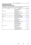
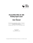
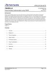
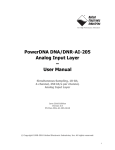
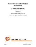
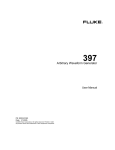
APPLICATION NOTE RX600 Series Hardware Data Collection and Filtering using the RX63N R01AN1430EU0100 Rev.1.00 Mar 22, 2013 Introduction The purpose of this application note is to show how to connect multiple peripherals in an application to “off-load” the simple work of periodically triggering the ADC and collecting the data into a buffer. In many applications it is necessary to collect Analog data from Sensors in real-time and process using complex filtering. Since many filters require multiple samples before any reasonable output can be expected, it is desirable to avoid all of the overhead of having interrupts and the CPU handling this data. It is preferred to handle one interrupt when the desired sample buffer size is ready. This Application note shows how to use 3 peripherals (MTU2, ADC and DMAC) in concert to analog data simultaneously and store in a memory buffer at rates up to ~300 kHz. In addition, it will show the filtering done by the Renesas Digital Signal Processing Library (DSP Lib) to increase the performance and reduce the work required for implementation of the filters. Target Device RX63N (R5F563NBDDFP) NOTE: This application note can be applied to other RX6x devices with minor changes. Basically, it will apply to any RX600 core device with the MTU2, 12 Bit ADC and DMAC, for example the RX62N. Contents 1. Demo Requirements ......................................................................................................................... 2 2. Building the Code .............................................................................................................................. 3 3. Hardware Set-up Description ............................................................................................................ 3 4. Software Demo Description .............................................................................................................. 4 5. Filtering .............................................................................................................................................. 6 6. Demo Debug/Runtime Hints, Tips and Tricks ................................................................................... 7 7. Limitations of Testing ...................................................................................................................... 11 8. References ...................................................................................................................................... 13 9. Glossary .......................................................................................................................................... 14 R01AN1430EU0100 Rev.1.00 Mar 22, 2013 Page 1 of 15 RX600 Series 1. Hardware Data Collection and Filtering using the RX63N Demo Requirements The following items are required in order to build and run this demonstration. 1.1 Required Renesas Development Tools (software) The following tools and their versions are required for building the demonstration and following the tutorial. Evaluation editions of these tools are all available for download from our website. • E2Studio version 1.1.1.7 (or later) http://www.renesas.com/download Web Search Keyword: “e2studio” • Renesas RX Standard Toolchain Version 1.2.1 Release 00 (or later) http://www.renesas.com/download Web Search Keyword: “RX Compiler” • Renesas DSP Library. Version 2.00 (or later). http://www.renesas.com/products/tools/middleware_and_drivers/c_splib/a_dsp/app_notes.jsp Select “Application Notes & Sample Code” Tab IMPORTANT: This project contains the correct version of the DSP binary and .h files to run this demo. The user is advised to go to the WEB and download the latest version and agree to the End-User-Licensing (EULA). This is important to get the latest documentation (not included in this app note) and bug-fixes (if any). 1.2 Required Hardware for Demo This application will run on either the RDK or the RSK platform. The following items are needed for the demo below. • • 1.3 RDK for RX63N (built-in debug feature). http://am.renesas.com/products/tools/introductory_evaluation_tools/renesas_demo_kits/yrdkrx63n/index.jsp 1 Analog Signal Source, OPTIONAL (i.e. Signal Generators, etc…) Demonstration Software The Demonstration software is intended for use with the Renesas RX63N RDK board. You will also need an analog signal source (optional) if you wish to sample real data. More detailed documentation on the RDK hardware is included with the kit or can be downloaded from the Renesas Web site. NOTE: The RDK has an “analog” source built-in (PWM with Low-pass filter) which can be used as the signal source. If not used, it may need to be disconnected (remove resistor) to attach an alternate source. R01AN1430EU0100 Rev.1.00 Mar 22, 2013 Page 2 of 15 RX600 Series 2. Hardware Data Collection and Filtering using the RX63N Building the Code Unzip the project into your workspace directory. The default workspace when unzipped to C: will be: C:\WorkSpace\an_r01an1430eu0100_rx63n_dsp\an_r01an1430eu0100_rx63n_dsp\Workspace After you unzip the project into the Workspace directory, the HardwareDebug should be the target when opening the e2Studio workspace. You can verify this by right clicking on the project in the e2Studio Explorer panel (rx_hw_datacollection) and then select : Build Configurations Set Active HardwareDebug. The demonstration software can then be built by using the “Build All” icon 3. . Hardware Set-up Description The demonstration is setup to collect data on ADC Unit 0, channel 3. The Hardware should be setup as shown in Figure 1 if using the optional signal generator. NOTE: You can pump the ADC Channel AN7 using a PWM timer which is passed through a Low-pass filter. CAUTION: Your analog sources should not violate the input specifications of the RX63N ADC channels found in the Hardware Manual. For example maximum VAN is listed as -0.3 to AVCC+0.3. See Absolute Maximum Ratings and ADC characteristics section of RX63N Hardware manual. AN71 Sig Gen J-Link RDK RX63N RS-232 LED5 LED6 PC.0 PC.1 TP0 TP1 Notes: 1.. Do not exceed the input specification of these ADC channels Figure 1: Hardware Setup Block Diagram NOTE: The J-Link debugger is built into the RDK, so it is not a separate item, just a region of the RDK as shown in the diagram. PC Communication port Settings: • • • • 115,200 baud 8 data bits 1 stop No Parity R01AN1430EU0100 Rev.1.00 Mar 22, 2013 Page 3 of 15 RX600 Series 4. Hardware Data Collection and Filtering using the RX63N Software Demo Description The following sections describe the Software’s operation. The demo does specific filtering on the collected data, but rather the user can easily modify the code in main() where the buffers are signaled as ready to do their own data processing. Please refer to Figure 2 for details on the peripheral signaling flow. MTU2 Channel 0 AD Trigger (160kHz) AD Complete Memory PING/PONG Buffer DMAC Channel ADC0 AN7 Data to Filter Task Complete Intr (PING/PONG Rdy)* * Change DMAC DST pointer to correct buffer in interrupt Figure 2: Peripheral Signaling Flow 4.1 PING/PONG Buffer Usage Many applications utilize complex filters to extract the required information from the Analog signals. These filters typically take multiple input samples to get usable outputs. In addition, these filters may require some extensive compute time. In this demonstration, we utilize a PING/PONG buffer scheme. We collect data into the PING buffer until it reaches the desired sample size. The software signals that the PING buffer is ready and continues to collect the samples in the PONG buffer. This gives the software enough samples and processing time to operate (i.e. run the filters) on the PING buffer while the hardware continues to collect data in the PONG buffer. Compute time allowed is then: Sample Rate Period * MIN_SAMPLE_SIZE before the next buffer is ready. See section 6.4, Buffer Size Considerations for the calculations for this demo. 4.2 MTU2 Setup The MTU2 is setup to create a periodic rate to the ADC Unit 0 to start a conversion. The sampling rate is set in MTU2.TGRA (compare A). This compare bit is used because it can trigger ADC start. The rate is based off the definition for sampling frequency in the common_def.h file. These are based on MACROs which define the CPU Clock, I clock, B clock and P clock (see the RX63N hardware manual for details on the clock structure). The maximum sample rate should not exceed the limits of the microcontroller. These limits are based on the various clock rates in the system, the number of channels converted, etc…. . For this demo, the RX63N is running at maximum clock on ADC and converting one channels, so the limit is ~312kHz . #define SAMPLING_FREQ 160000L // 160.0 kHz NOTE: If different crystal is installed the user will need to change the macros in r_bsp_config.h that set the crystal frequency. The PCLK driving the MTU2 basically is sourced by the CPU clock through some divider chains, so they are related. This is handled automatically by the build configurations for RDK. 4.3 ADC Setup This demo uses ADC controller 0. This converter was chosen because it has the ability to trigger the DMAC. It is set for a single scan with Channels 7 selected to convert. The ADC clock is programmed to maximum, 48MHz in the case of the default RDK for RX63N. R01AN1430EU0100 Rev.1.00 Mar 22, 2013 Page 4 of 15 RX600 Series 4.4 Hardware Data Collection and Filtering using the RX63N DMAC Setup We chose to use channel 3 of the DMAC controller. Although any DMAC channel can be used to do this ADC transfer, the designer must evaluate the system requirements when choosing channels to use. For example if you need to move data externally from and external ADC to memory using single cycle transfers, these are only supported by the EXDMAC. The DMAC is setup to operate as follows: • Triggered by ADC converter 0 complete • One word transfer per request • total transfers = MIN_SAMPLE_SIZE • Interrupt when complete R01AN1430EU0100 Rev.1.00 Mar 22, 2013 Page 5 of 15 RX600 Series 5. Hardware Data Collection and Filtering using the RX63N Filtering The Demo code uses the Renesas RX DSP Library (DSP Lib) to filter and separate the two frequencies into two buffers after the data is collected. For this demo we will show you the results based on “simulated” (mathematically generated) data. NOTE: This application note is not intended as a class in filtering. It is recommended the reader go to some of the references listed in the section 8 to review filter concepts. 5.1 Data Flow and Filter Construct The data flow for this demo is shown in Figure 3. The filters for this demo are “constructed” by creating handles for the various filters per the DSP Library Handle definitions. The reader is directed to the DSP Library Users Manual (included in the demo workspace) for reference to the content of the handles. 160kHz/unsigned 12Bit (ADC samples with offset) in_buff (ADC samples 20kHz/float 160kHz/float Float Conversion Boxcar N=8 nD = 8 5kHz/float High Pass FIR 31 Tap nD=4 result_buff1 Low Pass FIR 31 Tap nD=4 result_buff2 nD = decimation value Figure 3: Data Flow. The boxcar filter coefficients are as expected, 1/8 or .125. The FIR filter coefficients are calculated using ScopeFIR The low pass filter, 31 tap FIR, is set using pass band of 100Hz, stopband of 900Hz, 2dB of ripple and 30 dB of attenuation in the stopband. The Highpass filter, 31 tap FIR, is set using stopband upper of 100Hz, passband of 900Hz, 2dB of ripple and 40 dB of attenuation in the stopband. NOTE: The user is referred to section 8.2, ScopeFIR for additional information. 5.2 Generated Sample Data In the demonstration code, we use numerically generated sample data representing 50Hz and 1000Hz. The frequencies are defined at approximately line 50 of common_defs.h #define MY_HERTZ1 50.0f #define MY_HERTZ2 1000.0f The use of Generated data versus real ADC data is controlled by the define at line 40 of main.c #define GEN_DATA Please refer to section 6.2 to view the resulting sampled data. The demo code has the coefficients set up to do a low pass and a high pass and to separate these into two separate output buffers. To break on a complete pass of the filter (i.e. on full output buffer), you can add a breakpoint at the nop at line 472 of main.c as shown below: mtu2_ch0_ctl(OFF); // stop timer, stops all since it is trigger nop(); This will also stop data collection and let you prepare a log file to capture the result buffers. Please refer to section 6.3 to view the resulting filtered data R01AN1430EU0100 Rev.1.00 Mar 22, 2013 Page 6 of 15 RX600 Series 6. Hardware Data Collection and Filtering using the RX63N Demo Debug/Runtime Hints, Tips and Tricks The following section gives some tips on using this demo application. . 6.1 STOPPING Data Collection in Break As pointed out in earlier in this document, the data collection does not stop until told to do so by the processor. The easiest way to stop data collection is to just shutdown MTU2 Channel 0. The demo software provides a couple of methods to do this. It can be stopped by a function call to stop_data_collection(). It can be stopped at buffer boundaries by placing an eventpoint or breakpoint at the nop() at line 472 in check_for_break(). The stop_now variable is then set by pressing SW1 (stop_now is set in the Interrupt service routine of the switch). 6.2 Viewing Data in e2Studio using Excel In this section we are showing you how to view data using the e2studio Expressions window. Since most sample data will not look so clean coming out of your sensors, we will use the generated data for this exercise, but it works regardless of what is in the buffer. NOTE: The size of the buffer may affect the copy time. Other methods such as formatted memory save may also be used. So we add a breakpoint at a location where we want to sample / view some data, in this case we set a break at line 292 in main.c. In the expressions window we add big_sample_buff and expand the array as shown in Figure 4. Figure 4: Expressions Window Right Click the expressions window and “select all”, right click a second time and select copy expressions. You can now past the values into your favorite text editor window and remove any additional information that might prevent you for working with the data in subsequent “utility” programs such as ScopeDSP. NOTE: In the following sections we use this method to evaluate the output of the Filters. When we edit, we remove all but the actual values so we can read them into ScopeDSP (see section 8 ) for analysis. You can now import the text file into Excel and plot the values column. When plotting our MCU generated sample data, the resulting plot will look something like Figure 5 for the mixed sample data sine waves in this demo. You can see we’ve created data that goes from 0 to 4095, the full range of a 12 bit ADC. R01AN1430EU0100 Rev.1.00 Mar 22, 2013 Page 7 of 15 RX600 Series Hardware Data Collection and Filtering using the RX63N 4500 4000 3500 3000 2500 2000 Series1 1500 1000 500 1 70 139 208 277 346 415 484 553 622 691 760 829 898 967 1036 1105 1174 1243 1312 1381 1450 1519 1588 1657 1726 1795 1864 1933 2002 2071 2140 2209 2278 2347 2416 2485 2554 2623 2692 2761 2830 2899 2968 3037 3106 3175 0 Figure 5: Sample Excel Chart 6.3 Viewing filter results using ScopeDSP ScopeDSP is a low cost tool that can be used to quickly evaluate the results of your filter. In order to use it, you must first save the results into a file. We will save the memory contents and then with minor editing make it acceptable to ScopeDSP. This section shows you how to save the data for viewing in ScopeDSP; we will not give lessons in ScopeDSP. NOTE: For a step by step lab in generating filter coefficients and using ScopeDSP for analysis the user can refer to the DevCon Filter lab listed in section 8 of this document. The data can be captured by the serial port which logs the output when the SW1 is pressed. If you prefer that method, you can start a log on the serial console and capture the data when SW1 is pressed. NOTE: the data is output as High pass filter first and Low pass filter second. The alternate method is to use the Expressions window as described in section 6.3. If we save the filter output data into two files separate text files we can analyze them using ScopeDSP. IMPORTANT: The result buffer is the decimated output of the FIR / IIR filters. The FIR / IIR samples at 20kHz (box car output / boxcar decimate). We decimate by the value at line 45 of the common_def.h which is 4, so the result buffers represent a 20kHz/4 or 5kHz sample rate. The results of the two filters, high-pass and low pass are stored in buffers result_buff1 and result_buff2 respectively. result_buff1[result_buff_indx] = fir1_ptr[deci_cntr]; result_buff2[result_buff_indx++] = fir2_ptr[deci_cntr]; NOTE: Similar code is used for the IIR filter if you are running with USE_IIR uncommented. You can now read this “Time Data” into Scope DSP. Your resulting FFT should look like Figure 6. The sample data used to generate this plot is available in file HP_Sample_Data.txt in the DOCS directory of the project. You can now read this “Time Data” into Scope DSP. Your resulting FFT should look like Figure 7. The sample data used to generate this plot is available in file LP_Sample_Data.txt in the DOCS directory of the project. R01AN1430EU0100 Rev.1.00 Mar 22, 2013 Page 8 of 15 RX600 Series Hardware Data Collection and Filtering using the RX63N Figure 6: FFT of HP_Sample_Data.txt Figure 7: FFT of LP_Sample_Data.txt R01AN1430EU0100 Rev.1.00 Mar 22, 2013 Page 9 of 15 RX600 Series 6.4 Hardware Data Collection and Filtering using the RX63N Buffer Size Considerations The data rate at which you collect data along with the size of the buffer will affect the processing time you have in between the signaling of a “buffer ready” status. An example of this is the rate and buffer size used in this demo software. In this we collect 8*BOXCAR decimatevaule*FIR Decimate value. Example: MIN_SAMPLE_SIZE= 256 samples collected at a rate of 160kHz. Therefore you will get a BUFFER Ready status (PING or PONG) every (1/160kHz)*256 = 6.25µS*256 = 1.6mS. So you have 1.6mS to act on the 256 samples of data before the next buffer is ready. You can see this is verified by the scope shot in Figure 8. So it is important to validate that whatever you need to do with the data buffer (Filters, normalization, etc…) you have sufficient compute time to avoid the data collection buffer being overwritten by the incoming data (i.e. overwriting of the collected data by the hardware before the software has had time to “digest” it). 6.5 Buffer Usage Considerations The data that has been collected obviously must be processed. This data processing may be as simple as converting from raw ADC values to scaled values representing motor current, voltage, etc… to complex filtering. Since the hardware data collection does not stop, care should be taken that the data processing does not exceed the time calculated in section 6.3 In the demo code, the incoming data is “processed” in line 504 through 515. The code processes the data as follows: Lines 504 – Determines if data is in the PING or PONG buffer and sets index if in error. Line 508 – Calculates a pointer to the input buffer (PING or PONG)l Line 512 – scales the incoming data, converts to floats and copies to the floating point filter buffer. The code is written for clarity and may be optimized in your application. 6.6 Test Point Usage The Demo software provides two GPIO which can be used as test points for triggering or measurement points. These are declared (along with macros for setting and clearing) in the file common_def.h as follows: #define #define #define #define TRIGGER_PORT TRIGGER_PORT1 SET_TRIGGER_PORT(a) SET_TRIGGER_PORT1(a) LED5 LED6 TRIGGER_PORT = a TRIGGER_PORT1 = a The demo code as shipped is using the first test point, TRIGGER_PORT1 to indicate when data is being processed by the filter. The trigger port is set and cleared at lines 320 and 442 respectively. Scope shot shown in Figure 8. You can see that this combination of filters uses about 60% of the bandwidth at 160kHZ. Different combinations of Sample size and buffer sizes can be used to tune this usage. Figure 8: Trigger port 1 R01AN1430EU0100 Rev.1.00 Mar 22, 2013 Page 10 of 15 RX600 Series 7. Hardware Data Collection and Filtering using the RX63N Limitations of Testing This demo software combines the use of multiple peripherals and thus contains example code for these peripherals. 7.1.1 Alternate Filters The software has all the structures necessary to test and evaluate other filter forms, in this case IIR and Fixed Point IIIR. These are controlled by definitions at lines 35, 36 , and 37. Only one of these lines should be “uncommented “ at a time.. The demo comes with the USE_FIR uncommented. The floating point IIR filters are tested; the fixed point filters are left to the reader to validate. 7.1.2 DMAC Driver The demo code for the application note contains a mini-DMA Driver. It supports the programming of multiple channels on the DMAC, but all permutations have not been tested. It has only been used to the extent required by this application note, which is DMAC Channel 3 triggered by ADC0 Complete, Transfer Complete Interrupt enable. 7.1.3 ADC Driver The demo code for the application note contains a mini-ADC Driver. It supports the programming of multiple converters and channels on the ADC, but all permutations have not been tested. It has only been used to the extent required by this application note, that is ADC0, channels 0 enabled for conversion, single scan, and AD Start triggered by MTU2 channel 0. 7.1.4 MTU2 Channel 0 Usage MTU2 channel 0 was chosen to trigger the ADC, but any of the MTU2 channels that can create an ADST (A/D Conversion Start) can be used. In addition, you can save the timer and use /ADTRG (ADC trigger input) to start the process if you have some fixed rate hardware signal related to the analog sampling. 7.1.5 RSK Considerations Much of the demo is based on RDK demo code and as such should be very familiar to those who have built tutorials on the RSK or RDK. We have not endeavored to strip any of this so some functions are available to enhance this demo code (i.e. switch and LCD functions), but are not extensively used. SW1, SW2 and SW3: The switches are programmed and available for use to enahce the demo. We currently use SW1 to set the stop_now flag. So long as the breakpoint is left the check for break function, the program will stop on a filter processing boundary (i.e. a full result buffer). LED: The LED ports make nice trigger points. Currently we use only LED5 and LED6. LED5 is toggled every time the ADC Interrupt service routine is called, which should be sample rate/sample size. LED6 is tuned when a buffer is ready for processing and tuned off when the filter processing is done. The other LED are available for the user. LCD: The LCD is initialized as in RSK tutorials and a SPLASH screen is displayed before the Data collection is actually running. The display is updated with the message “Filter Running” once the Hardware collection and filters are actually running. Beyond that, the LCD may be used to post other messages if desired. CONSOLE: We have included code to enable stdin, stdout and stderr console operation. The Serial port may be connected to a terminal emulator set as follows: 115200 baud, 8 data, 1 stop, no Parity. We use the console to output sample and result data as part of the code and this data can be logged using the appropriate terminal emulation program ® such as TeraTerm or Hyperterm. CRYSTAL Selection: The demo program runs on both the RDK and the RSK. When connecting to the target using E1/J-Link debugger, the user should select 12.00 MHz crystal for the RDK. R01AN1430EU0100 Rev.1.00 Mar 22, 2013 Page 11 of 15 RX600 Series 7.1.6 Hardware Data Collection and Filtering using the RX63N Reducing / Expanding the concept This demo is written to fulfill a very specific data collection concept, one analog channels at a high rate and then post processed by some numerical function. To reduce this should be a very simple process (not undertaken here). The user can change the sample size, the sample rate, etc. by changing the specific definitions in common_def.h To expand the concept is just a little more difficult. You can select multiple channels for conversion. You will need to change the DMAC programming to move more of the result registers when making the transfer, which might require using adjacent channels of the ADC or use the DTC for non-adjacent channels. The DTC can be triggered by ADC1 and DTC operations can be chained to the transfer any number of ADC channels in the microcontroller. Of course the total data collection rate will be based on the ADC Clock, the number of channels and the size of the data buffer. This exercise is left to the reader. R01AN1430EU0100 Rev.1.00 Mar 22, 2013 Page 12 of 15 RX600 Series 8. Hardware Data Collection and Filtering using the RX63N References 8.1 Renesas References RX63N Group User’s Manuals: Hardware Manual, R01UH0041EJ0100 Renesas Demo Kit for RX63N Documents (available on RDK Installer) • User’s Manual • RDK Schematic • RDK Quick Start Guide RX63N Group Application Notes • Renesas Starter Kit Sample Code for RX63N, R01AN1396EG0100 Renesas RX DSP Library (DSP), Version 2.00 • RX DSP Library User’s Manual: Software, R01UW0096ES0100 • HEW / RXC Sample Project, R01AN1465ES0100 DevCon RX Labs (available on DevCon website) • • 8.2 DevCon 2012 Lab CL03I FPU Filter Lab Devcon 2012 Lab 1L01I, Optimizing RX Performance Lab External References Iowegian ScopeFIR, ScopeDSP, and Scope IIR tools available at http://www.iowegian.com/ DSP Guru http://www.dspguru.com/ WinFilter http://www.winfilter.20m.com The Scientist and Engineer's Guide to Digital Signal Processing, copyright ©1997-1998 by Steven W. Smith. For more information visit the book's website at: http://www.DSPguide.com Signal Processing for Communications: http://www.sp4comm.org/ C. E. Shannon, "Communication in the presence of noise", Proc. Institute of Radio Engineers, vol. 37, no. 1, pp. 10–21, Jan. 1949. Reprint as classic paper in: Proc. IEEE, vol. 86, no. 2, (Feb. 1998) R01AN1430EU0100 Rev.1.00 Mar 22, 2013 Page 13 of 15 RX600 Series 9. Hardware Data Collection and Filtering using the RX63N Glossary ADC – Analog to Digital Converter CMT – Compare Match Timer CPU – Central Processing Unit DMAC – Direct Memory Access Controller DSC – Digital Signal Controller DSP – Digital Signal Processor DTC – Data Transfer Controller FIR – Finite Impulse Response GPIO – General Purpose Input/Output IIR – Infinite Impulse Response LCD – Liquid Crystal Display MTU2 – Multifunction Timer Unit 2 PCLK – Peripheral Clock RSK - Renesas Starter Kit R01AN1430EU0100 Rev.1.00 Mar 22, 2013 Page 14 of 15 RX600 Series Hardware Data Collection and Filtering using the RX63N Website and Support Renesas Electronics Website http://www.renesas.com/ Inquiries http://www.renesas.com/inquiry All trademarks and registered trademarks are the property of their respective owners. R01AN1430EU0100 Rev.1.00 Mar 22, 2013 Page 15 of 15 Revision Record Rev. 1.00 Date Mar 22, 2013 Description Page Summary — First edition issued A-1 General Precautions in the Handling of MPU/MCU Products The following usage notes are applicable to all MPU/MCU products from Renesas. For detailed usage notes on the products covered by this document, refer to the relevant sections of the document as well as any technical updates that have been issued for the products. 1. Handling of Unused Pins Handle unused pins in accord with the directions given under Handling of Unused Pins in the manual. ⎯ The input pins of CMOS products are generally in the high-impedance state. In operation with an unused pin in the open-circuit state, extra electromagnetic noise is induced in the vicinity of LSI, an associated shoot-through current flows internally, and malfunctions occur due to the false recognition of the pin state as an input signal become possible. Unused pins should be handled as described under Handling of Unused Pins in the manual. 2. Processing at Power-on The state of the product is undefined at the moment when power is supplied. ⎯ The states of internal circuits in the LSI are indeterminate and the states of register settings and pins are undefined at the moment when power is supplied. In a finished product where the reset signal is applied to the external reset pin, the states of pins are not guaranteed from the moment when power is supplied until the reset process is completed. In a similar way, the states of pins in a product that is reset by an on-chip power-on reset function are not guaranteed from the moment when power is supplied until the power reaches the level at which resetting has been specified. 3. Prohibition of Access to Reserved Addresses Access to reserved addresses is prohibited. ⎯ The reserved addresses are provided for the possible future expansion of functions. Do not access these addresses; the correct operation of LSI is not guaranteed if they are accessed. 4. Clock Signals After applying a reset, only release the reset line after the operating clock signal has become stable. When switching the clock signal during program execution, wait until the target clock signal has stabilized. ⎯ When the clock signal is generated with an external resonator (or from an external oscillator) during a reset, ensure that the reset line is only released after full stabilization of the clock signal. Moreover, when switching to a clock signal produced with an external resonator (or by an external oscillator) while program execution is in progress, wait until the target clock signal is stable. 5. Differences between Products Before changing from one product to another, i.e. to a product with a different part number, confirm that the change will not lead to problems. ⎯ The characteristics of an MPU or MCU in the same group but having a different part number may differ in terms of the internal memory capacity, layout pattern, and other factors, which can affect the ranges of electrical characteristics, such as characteristic values, operating margins, immunity to noise, and amount of radiated noise. When changing to a product with a different part number, implement a system-evaluation test for the given product. Notice 1. Descriptions of circuits, software and other related information in this document are provided only to illustrate the operation of semiconductor products and application examples. You are fully responsible for the incorporation of these circuits, software, and information in the design of your equipment. Renesas Electronics assumes no responsibility for any losses incurred by you or third parties arising from the use of these circuits, software, or information. 2. Renesas Electronics has used reasonable care in preparing the information included in this document, but Renesas Electronics does not warrant that such information is error free. Renesas Electronics 3. Renesas Electronics does not assume any liability for infringement of patents, copyrights, or other intellectual property rights of third parties by or arising from the use of Renesas Electronics products or assumes no liability whatsoever for any damages incurred by you resulting from errors in or omissions from the information included herein. technical information described in this document. No license, express, implied or otherwise, is granted hereby under any patents, copyrights or other intellectual property rights of Renesas Electronics or others. 4. You should not alter, modify, copy, or otherwise misappropriate any Renesas Electronics product, whether in whole or in part. Renesas Electronics assumes no responsibility for any losses incurred by you or 5. Renesas Electronics products are classified according to the following two quality grades: "Standard" and "High Quality". The recommended applications for each Renesas Electronics product depends on third parties arising from such alteration, modification, copy or otherwise misappropriation of Renesas Electronics product. the product's quality grade, as indicated below. "Standard": Computers; office equipment; communications equipment; test and measurement equipment; audio and visual equipment; home electronic appliances; machine tools; personal electronic equipment; and industrial robots etc. "High Quality": Transportation equipment (automobiles, trains, ships, etc.); traffic control systems; anti-disaster systems; anti-crime systems; and safety equipment etc. Renesas Electronics products are neither intended nor authorized for use in products or systems that may pose a direct threat to human life or bodily injury (artificial life support devices or systems, surgical implantations etc.), or may cause serious property damages (nuclear reactor control systems, military equipment etc.). You must check the quality grade of each Renesas Electronics product before using it in a particular application. You may not use any Renesas Electronics product for any application for which it is not intended. Renesas Electronics shall not be in any way liable for any damages or losses incurred by you or third parties arising from the use of any Renesas Electronics product for which the product is not intended by Renesas Electronics. 6. You should use the Renesas Electronics products described in this document within the range specified by Renesas Electronics, especially with respect to the maximum rating, operating supply voltage range, movement power voltage range, heat radiation characteristics, installation and other product characteristics. Renesas Electronics shall have no liability for malfunctions or damages arising out of the use of Renesas Electronics products beyond such specified ranges. 7. Although Renesas Electronics endeavors to improve the quality and reliability of its products, semiconductor products have specific characteristics such as the occurrence of failure at a certain rate and malfunctions under certain use conditions. Further, Renesas Electronics products are not subject to radiation resistance design. Please be sure to implement safety measures to guard them against the possibility of physical injury, and injury or damage caused by fire in the event of the failure of a Renesas Electronics product, such as safety design for hardware and software including but not limited to redundancy, fire control and malfunction prevention, appropriate treatment for aging degradation or any other appropriate measures. Because the evaluation of microcomputer software alone is very difficult, please evaluate the safety of the final products or systems manufactured by you. 8. Please contact a Renesas Electronics sales office for details as to environmental matters such as the environmental compatibility of each Renesas Electronics product. Please use Renesas Electronics products in compliance with all applicable laws and regulations that regulate the inclusion or use of controlled substances, including without limitation, the EU RoHS Directive. Renesas Electronics assumes no liability for damages or losses occurring as a result of your noncompliance with applicable laws and regulations. 9. Renesas Electronics products and technology may not be used for or incorporated into any products or systems whose manufacture, use, or sale is prohibited under any applicable domestic or foreign laws or regulations. You should not use Renesas Electronics products or technology described in this document for any purpose relating to military applications or use by the military, including but not limited to the development of weapons of mass destruction. When exporting the Renesas Electronics products or technology described in this document, you should comply with the applicable export control laws and regulations and follow the procedures required by such laws and regulations. 10. It is the responsibility of the buyer or distributor of Renesas Electronics products, who distributes, disposes of, or otherwise places the product with a third party, to notify such third party in advance of the contents and conditions set forth in this document, Renesas Electronics assumes no responsibility for any losses incurred by you or third parties as a result of unauthorized use of Renesas Electronics products. 11. This document may not be reproduced or duplicated in any form, in whole or in part, without prior written consent of Renesas Electronics. 12. Please contact a Renesas Electronics sales office if you have any questions regarding the information contained in this document or Renesas Electronics products, or if you have any other inquiries. (Note 1) "Renesas Electronics" as used in this document means Renesas Electronics Corporation and also includes its majority-owned subsidiaries. (Note 2) "Renesas Electronics product(s)" means any product developed or manufactured by or for Renesas Electronics. SALES OFFICES http://www.renesas.com Refer to "http://www.renesas.com/" for the latest and detailed information. Renesas Electronics America Inc. 2880 Scott Boulevard Santa Clara, CA 95050-2554, U.S.A. Tel: +1-408-588-6000, Fax: +1-408-588-6130 Renesas Electronics Canada Limited 1101 Nicholson Road, Newmarket, Ontario L3Y 9C3, Canada Tel: +1-905-898-5441, Fax: +1-905-898-3220 Renesas Electronics Europe Limited Dukes Meadow, Millboard Road, Bourne End, Buckinghamshire, SL8 5FH, U.K Tel: +44-1628-651-700, Fax: +44-1628-651-804 Renesas Electronics Europe GmbH Arcadiastrasse 10, 40472 Düsseldorf, Germany Tel: +49-211-65030, Fax: +49-211-6503-1327 Renesas Electronics (China) Co., Ltd. 7th Floor, Quantum Plaza, No.27 ZhiChunLu Haidian District, Beijing 100083, P.R.China Tel: +86-10-8235-1155, Fax: +86-10-8235-7679 Renesas Electronics (Shanghai) Co., Ltd. Unit 204, 205, AZIA Center, No.1233 Lujiazui Ring Rd., Pudong District, Shanghai 200120, China Tel: +86-21-5877-1818, Fax: +86-21-6887-7858 / -7898 Renesas Electronics Hong Kong Limited Unit 1601-1613, 16/F., Tower 2, Grand Century Place, 193 Prince Edward Road West, Mongkok, Kowloon, Hong Kong Tel: +852-2886-9318, Fax: +852 2886-9022/9044 Renesas Electronics Taiwan Co., Ltd. 13F, No. 363, Fu Shing North Road, Taipei, Taiwan Tel: +886-2-8175-9600, Fax: +886 2-8175-9670 Renesas Electronics Singapore Pte. Ltd. 80 Bendemeer Road, Unit #06-02 Hyflux Innovation Centre Singapore 339949 Tel: +65-6213-0200, Fax: +65-6213-0300 Renesas Electronics Malaysia Sdn.Bhd. Unit 906, Block B, Menara Amcorp, Amcorp Trade Centre, No. 18, Jln Persiaran Barat, 46050 Petaling Jaya, Selangor Darul Ehsan, Malaysia Tel: +60-3-7955-9390, Fax: +60-3-7955-9510 Renesas Electronics Korea Co., Ltd. 11F., Samik Lavied' or Bldg., 720-2 Yeoksam-Dong, Kangnam-Ku, Seoul 135-080, Korea Tel: +82-2-558-3737, Fax: +82-2-558-5141 © 2013 Renesas Electronics Corporation. All rights reserved. Colophon 2.2