1
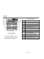
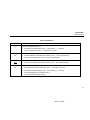
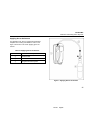
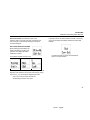
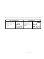
BW TECHNOLOGIES
GasAlertMax
Gas Detector
User Manual
D1430 (English)
JUNE 2001
© 2001 BW Technologies, All rights reserved. Printed in Canada
All product names are trademarks of their respective companies.
D1430
English
Limited Warranty & Limitation of Liability
BW Technologies warrants this product to be free from defects in material and workmanship under normal use and service for a period of two years, beginning
on the date of shipment. Parts, product repairs and services are warranted for 90 days. This warranty extends only to the original buyer or end-user customer of a
BW Technologies authorized reseller, and does not apply to fuses, disposable batteries or to any product which, in BW Technologies’ opinion, has been misused,
altered, neglected or damaged by accident or abnormal conditions of operation or handling. BW Technologies warrants that software will operate substantially in
accordance with its functional specifications for 90 days and that it has been properly recorded on non-defective media. BW Technologies does not warrant that
software will be error free or operate without interruption.
BW Technologies authorized resellers shall extend this warranty on new and unused products to end-user customers only but have no authority to extend a
greater or different warranty on behalf of BW Technologies. Warranty support is available if product is purchased through a BW Technologies authorized sales
outlet or Buyer has paid the applicable international price. BW Technologies reserves the right to invoice Buyer for importation costs of repair/replacement parts
when product purchased in one country is submitted for repair in another country.
BW Technologies’ warranty obligation is limited, at BW Technologies’ option, to refund of the purchase price, free of charge repair, or replacement of a defective
product which is returned to a BW Technologies authorized service center within the warranty period.
To obtain warranty service, contact your nearest BW Technologies authorized service center or send the product, with a description of the difficulty, postage and
insurance prepaid (FOB Destination), to the nearest BW Technologies authorized service center. BW Technologies assumes no risk for damage in transit.
Following warranty repair, the product will be returned to Buyer, transportation prepaid (FOB Destination). If BW Technologies determines that the failure was
caused by misuse, alteration, accident or abnormal condition of operation or handling, BW Technologies will provide an estimate of repair costs and obtain
authorization before commencing the work. Following repair, the product will be returned to the Buyer transportation prepaid and the Buyer will be billed for the
repair and return transportation charges (FOB Shipping Point).
THIS WARRANTY IS BUYER'S SOLE AND EXCLUSIVE REMEDY AND IS IN LIEU OF ALL OTHER WARRANTIES, EXPRESS OR IMPLIED, INCLUDING BUT
NOT LIMITED TO ANY IMPLIED WARRANTY OF MERCHANTABILITY OR FITNESS FOR A PARTICULAR PURPOSE. BW TECHNOLOGIES SHALL NOT BE
LIABLE FOR ANY SPECIAL, INDIRECT, INCIDENTAL OR CONSEQUENTIAL DAMAGES OR LOSSES, INCLUDING LOSS OF DATA, WHETHER ARISING
FROM BREACH OF WARRANTY OR BASED ON CONTRACT, TORT, RELIANCE OR ANY OTHER THEORY.
Since some countries or states do not allow limitation of the term of an implied warranty, or exclusion or limitation of incidental or consequential damages, the
limitations and exclusions of this warranty may not apply to every buyer. If any provision of this Warranty is held invalid or unenforceable by a court of competent
jurisdiction, such holding will not affect the validity or enforceability of any other provision.
BW Technologies Ltd.
nd
2840 – 2 Ave. SE
Calgary, AB T2A 7X9
Canada
BW Technologies Inc. (America)
2307 Oak Lane, Suite 2A100
Grande Prairie, TX 75051
USA
BW Europe Ltd.
101 Heyford Park,
Upper Heyford, Oxfordshire OX25 5HA
United Kingdom
05/01
D1430 (1084539)
English
Table of Contents
Title
Page
Introduction ...........................................................................................................................
Contacting BW Technologies ................................................................................................
Safety Information - Read First .............................................................................................
Getting Started......................................................................................................................
Activating the Detector ..........................................................................................................
User Downloadable Datalogger (Option) Test ..................................................................
Sensor Test......................................................................................................................
Self-Test Pass..................................................................................................................
Self-Test Fail....................................................................................................................
Sampling Pump Test ........................................................................................................
Battery Test......................................................................................................................
Deactivating the Detector ......................................................................................................
Confidence Beep...................................................................................................................
User Option Menu .................................................................................................................
Latched Alarms ................................................................................................................
Change the Date and Time ..............................................................................................
Alarms...................................................................................................................................
Gas Exposures Computed ...............................................................................................
Viewing Gas Exposures ...................................................................................................
Gas Alarm Setpoints ........................................................................................................
Resetting Gas Alarm Setpoints ........................................................................................
Stopping a Gas Alarm ......................................................................................................
Sensor Alarm ...................................................................................................................
Pump Alarms ...................................................................................................................
i
D1430 (108539)
English
1
2
2
6
10
11
11
12
12
12
12
13
14
14
15
15
16
20
21
21
22
22
23
23
GasAlertMax
Users Manual
Low Battery Alarm............................................................................................................
Automatic Shutdown Alarm ..............................................................................................
Calibration and Setting Alarm Setpoints ................................................................................
Guidelines ........................................................................................................................
Applying Gas to the Sensors............................................................................................
Calibration Procedure ......................................................................................................
Start Calibration ..........................................................................................................
Auto Zero and Oxygen Sensor Calibration ..................................................................
Pass Code Protect ......................................................................................................
Auto Span ...................................................................................................................
Alarm Setpoints................................................................................................................
Setting the Low Alarm Setpoint ...................................................................................
Setting the High Alarm Setpoint ..................................................................................
Setting the Remaining Alarm Setpoints .......................................................................
Maintenance .........................................................................................................................
Replacing the Battery.......................................................................................................
Pump Calibration..............................................................................................................
Replacing a Sensor, Pump or Pump Filter .......................................................................
User Option - Sensor Disable...........................................................................................
User Option - Pass Code Protection ................................................................................
If the Detector Does Not Work ..............................................................................................
Replacement Parts and Accessories.....................................................................................
Specifications........................................................................................................................
Appendix A............................................................................................................................
User Downloadable Datalogger Operation .......................................................................
E.D.N. (Excel Datalog Manager) ......................................................................................
Direct Import to Compatible Programs .............................................................................
ii
D1430
English
23
23
24
24
25
26
26
26
27
28
29
29
30
31
34
34
36
38
40
41
42
45
46
A
C
D
H
List of Tables
Table
1.
2.
3.
4.
5.
6.
7.
8.
9.
10.
11.
12.
13.
14.
A
Title
Page
Gases Monitored........................................................................................................................
International Symbols.................................................................................................................
GasAlertMax Detector ................................................................................................................
Display Elements .......................................................................................................................
Pushbuttons ...............................................................................................................................
Alarms........................................................................................................................................
Computed Gas Exposures .........................................................................................................
Gas Alarm Setpoints ..................................................................................................................
Factory Set Alarm Setpoints.......................................................................................................
Applying Gas to the Sensors......................................................................................................
Replacing the Battery.................................................................................................................
Replacing a Sensor, Pump or Pump Filter .................................................................................
Troubleshooting Tips..................................................................................................................
Replacement Parts and Accessories..........................................................................................
Direct Import Datalogger Status Codes......................................................................................
iii
D1430 (108539)
English
1
5
7
8
9
16
20
21
22
25
35
39
42
45
H
GasAlertMax
Users Manual
iv
D1430
English
List of Figures
Figure
1.
2.
3.
4.
5.
Title
Page
GasAlertMax Detector ................................................................................................................
Display Elements .......................................................................................................................
Applying Gas to the Sensors......................................................................................................
Replacing the Battery.................................................................................................................
Replacing a Sensor, Pump or Pump Filter .................................................................................
v
D1430 (108539)
English
7
8
25
35
39
GasAlertMax
Users Manual
CAUTION: FOR SAFETY REASONS THIS EQUIPMENT
MUST BE OPERATED AND SERVICED BY QUALIFIED
PERSONNEL ONLY. READ AND UNDERSTAND
INSTRUCTION MANUAL COMPLETELY BEFORE
OPERATING OR SERVICING.
GasAlertMax Multi-Gas Detector
GAMAX-4 (Serial numbers with prefix 3-######)
The detector comes complete with motorized sampling
pump.
GasAlertMax with Black Box Datalogger
Provides full time continuous datalogging while the detector
is operating. Wrap around memory ensures the most recent
data is always saved. Data cannot be accessed by the user.
Data is retrievable by an authorized BW factory service
center in the event of an incident or occurrence.
GasAlertMax 4-Gas Detector
Order Number
Description
GAMAX2-4
GasAlertMax Detector
GAMAX2-DL1
GasAlertMax with Black Box Datalogger
GAMAX2-DL2
GasAlertMax with User Downloadable
Datalogger
GasAlertMax with User Downloadable Datalogger
Provides full time continuous datalogging while the
instrument is operating. Data is saved on a convenient
MultiMediaCard and can be removed and downloaded by the
user. Data is imported into standard office software
(Microsoft® Excel, Access etc.)
vi
D1430
English
GasAlertMax
Table 1. Gases Monitored
Introduction
WWarning
Gas
Unit of Measure
To ensure your personal safety, read “Safety
Information” before you use the detector.
carbon monoxide
(CO)
parts per million (ppm)
The GasAlertMax gas detector (“the detector”) warns of
hazardous gas at levels above factory set alarm setpoints.
This product is a gas detector.
hydrogen sulfide
(H2S)
parts per million (ppm)
oxygen (O2)
percent by volume (%)
The detector is a personal safety device. It is your
responsibility to respond properly to the alarm.
combustible gases
(LEL)
percent of lower explosive
limit (% LEL)
Table 1 lists the gases monitored.
1
D1430
English
GasAlertMax
User Manual
Contacting BW Technologies
Safety Information - Read First
To contact BW Technologies, call:
Use the detector only as specified in this manual, otherwise
the protection provided by the detector may be impaired.
USA and Canada: 1-800-663-4164
BW America: 1-888-749-8878
Europe and U.K.: +44 (0) 1869-233004
Anywhere in the world: +1-403-248-9226
Address correspondence to:
BW Technologies Ltd.
2840 – 2 Avenue S.E.
Calgary, AB T2A 7X9
CANADA
Or visit us on the World Wide Web: www.gasmonitors.com
ISO 9001
A Warning identifies conditions and actions that pose
hazard(s) to the user; a Caution identifies conditions and
actions that may damage the detector.
International symbols used on the detector and in this manual
are explained in Table 2.
Read the Warnings and Cautions on the following pages
before using the detector.
v=Note
This instrument contains a rechargeable battery.
Do not mix with the solid waste stream. Spent
batteries should be disposed of by a qualified
recycler or hazardous materials handler.
2
D1430
English
GasAlertMax
Safety Information - Read First
WWarning
To avoid possible personal injury:
⇒
Substitution of components may impair Intrinsic Safety.
⇒
Do not use the detector if it is damaged. Before you use the detector, inspect the case. Look for cracks or
missing plastic.
⇒
If the detector is damaged or something is missing, contact BW Technologies immediately (see p. 2).
⇒
Make sure the back is closed and fastened, and the battery is locked in place before you operate the detector.
⇒
Use only a sensor specifically designed for your GasAlertMax model. (See the section, "Replacement Parts
and Accessories.")
⇒
Periodically test the sensor’s response to gas by exposing the detector to a targeted gas concentration that
exceeds the High Alarm setpoint. Manually verify that the audible and visual alarms are activated.
⇒
Prior to each day’s usage sensitivity must be tested on a known concentration of the target combustible gas
(methane, etc.) equivalent to 25-50% of full-scale concentration (accuracy must be within 0 to +20% of actual).
Accuracy may be corrected by recalibrating the instrument.
⇒
Calibrate the detector before first-time use, and then at least once every 90 days.
⇒
Do not turn off the detector during a work shift. Turning off the detector resets the TWA (time-weighted
average) and maximum gas exposure values to 0. (See the section, “Alarms.”)
⇒
It is recommended that the accuracy of the GasAlertMax be checked with known concentration calibration
gas before each day’s use and immediately after any known exposure to contaminants.
3
D1430
English
GasAlertMax
User Manual
WWarnings (cont.)
⇒
Make sure the pump filter is not blocked.
⇒
The LEL sensor is factory calibrated to methane. If monitoring a different combustible gas, calibrate the
sensor using the appropriate gas.
⇒
High off-scale % LEL readings may indicate an explosive concentration.
⇒
Protect the LEL sensor from exposure to lead compounds, silicones, and chlorinated hydrocarbons.
Although certain organic vapors (such as, leaded gasoline and halogenated hydrocarbons) may temporarily
inhibit sensor performance, in most cases, the sensor will recover after calibration.
⇒
Any rapid up-scaling reading followed by a declining or erratic reading may indicate a gas concentration
beyond upper scale limit, which may be hazardous.
⇒
Use only Black & Decker VersaPak batteries, properly charged and installed in the detector case. (See the
section, "Replacement Parts and Accessories.")
⇒
Only charge batteries using BW Technologies charger (such as the D4-VP130 and D4-VP140). Do not use any
other charger. Failure to observe this precaution could lead to fire or explosion.
⇒
Do not change or charge batteries in a hazardous location. Doing so will impair the Intrinsic Safety of the
unit, and may lead to fire or explosion.
⇒
Read and observe all instructions and precautions in the literature provided with the charger. Failure to do so
may result in fire, electric shock, or other forms of personal injury or property damage.
4
D1430
English
GasAlertMax
Safety Information - Read First
Caution
To avoid possible damage to the detector:
⇒
Extended exposure of the GasAlertMax to certain concentrations of combustible gases and air may stress a
detector element, which can seriously affect its performance. If an alarm occurs due to high concentration of
combustible gases, recalibration should be performed, or if needed the sensor replaced.
⇒
Do not test the combustible sensors response with a butane cigarette lighter; doing so will damage the sensor.
⇒
Do not expose the detector to electrical shock and/or severe continuous mechanical shock.
⇒
Do not attempt to disassemble, adjust, or service the detector unless instructions for that procedure are
contained in the manual and/or that part is listed as a replacement part. Use only BW Technologies
replacement parts.
⇒
Do not immerse the detector in liquids.
⇒
The detector Warranty will be voided if customer personnel or third parties damage the detector during repair
attempts. Non-BW Technologies repair/service attempts void this Warranty.
Table 2. International Symbols
Symbol
Meaning
Approved by Canadian Standards Association to both U.S. and Canadian Standards.
P
Conforms to European Union directives.
5
D1430
English
GasAlertMax
User Manual
Getting Started
The detector comes with sensors installed. The
"Maintenance" section describes how to install the batteries.
The items listed below are included with your detector. If the
detector is damaged or something is missing, contact the
place of purchase immediately.
To become familiar with the features and functions of the
detector, study the following figures and tables:
•
Black & Decker VersaPak Batteries (2 cells)
•
•
Figure 1 and Table 3 describe the detector’s
components.
VersaPak battery VAC charger
•
•
H2S/CO sensor (dual sensor)
Figure 2 and Table 4 describe the detector’s display
elements.
•
O2 sensor
•
Table 5 describes the detector’s pushbuttons.
•
LEL sensor
•
Calibration hose
•
Sampling hose
To order replacement parts, see the section "Replacement
Parts and Accessories."
6
D1430
English
GasAlertMax
Getting Started
Table 3. GasAlertMax Detector
Item
Function
A
Audible Alarm
B
Visual Alarm
C
Display
D
Pushbuttons
E
Accessory Output Jack
F
Pump and Pump Filter
G
Sensors
H
Battery
I
Datalogger (optional)
Figure 1. GasAlertMax Detector
7
D1430
English
GasAlertMax
User Manual
Table 4. Display Elements
Item
A
Set Value
B
Increment or Decrement Value
C
Gas Cylinder
D
Battery
E
Automatically Span the Sensor
F
Gas Identifier Bars
G
Alarm Setpoint or Alarm
H
Automatically Zero the Sensor
I
Pump
J
Multi-Gas Alarm Condition or
View TWA and Maximum Gas Exposure
K
Real Time Calendar (Date, Month, Year)
L
Optional Datalogger Card Indicator
M
Optional Datalogger FAIL Indicator
N
Other Symbols – future Use
Figure 2. Display Elements
Note
The display backlight automatically activates for
10 seconds whenever there is insufficient light to
view the display and during alarm conditions. Any
pushbutton reactivates the backlight.
Function
8
D1430
English
GasAlertMax
Getting Started
Table 5. Pushbuttons
Pushbutton
E
Description
To turn on the detector, press E.
•
To initiate the Confidence Beep, press B while pressing E at startup.
•
To turn off the detector, press E and hold for 5 seconds.
G
•
To decrement the displayed value, press G.
CAL
•
To initiate calibration and setting alarm setpoints, press B and G simultaneously.
•
To enter the user options menu, press F and G simultaneously.
F
•
To increment the displayed value, press F.
TWA
MAX
•
To view the TWA and maximum gas exposures, press B and F simultaneously.
B
•
To initiate calibration and setting alarm setpoints, press B and G simultaneously.
OK
•
To manually reset maximum (peak) hold, press B and hold for 5 seconds.
•
To initiate the Confidence Beep, press B while pressing E at startup.
•
To initiate Sampling Pump recalibration press B.
•
To acknowledge latched alarms press B.
9
D1430
English
GasAlertMax
User Manual
Activating the Detector
⇒
7.
The display shows the Low and High Alarm
setpoints.
8.
The display reads tESt (test) as the detector tests
the sensors.
9.
The oxygen sensor is calibrated automatically.
To activate the detector, press E in a normal
atmosphere (20.9% oxygen).
Self-Test
The detector performs the actions in steps 1-9. Manually
check that all actions occur.
1.
2.
If the battery is low, M LOW flashes, the display
reads OFF. Replace the battery and restart the
detector.
The display shows all elements.
3.
The detector beeps and flashes.
4.
The detector briefly turns on the backlight.
User Downloadable model only (5 and 6)
5.
The detector tests data card. Display advises if
card is present and ready for use (page 11).
6.
The display shows the time, day and date.
If the detector fails steps 1-9, see the section, “If the Detector
Does Not Work.”
10
D1430
English
GasAlertMax
Activating the Detector
MultiMediaCard icon
is displayed continuously on Black
Box Dataloggers and when card is present in User
Downloadable Dataloggers.
User Downloadable Datalogger (Option) Test
Sensor Test
The pump draws air over the sensors. If a sensor fails the
self-test, the audible alarm emits a slow modulating tone and
the visual alarm flashes slowly. Sensor fail display advises
failed sensor:
The detector tests the data card. The display advises if the
card is present and ready for use.
If the card is missing or malfunctioning, the detector beeps
and flashes quickly. The display
advises card error and the detector
continues the self-test and proceeds
to normal operation.
The detector does not require
the data card to be present
or functioning to operate.
Add or change the data card on User Downloadable units at
any time. The detector supports card insertion and removal
while instrument is active.
11
D1430
English
GasAlertMax
User Manual
Self-Test Pass
Sampling Pump Test
If the detector passes the self-test, the detector begins
normal operation. The display shows the ambient gas
readings:
The pump is tested continuously after activation. If the pump
fails the display will show:
Note
The detector starts recording the maximum gas exposure
and calculating the TWA (time-weighted average).
Self-Test Fail
If the detector fails the self-test, see the section, “If the
Detector Does Not Work.”
If Pump Alarm continues for more than 5 seconds
and the display advises Inlet Blocked, see “Pump
Calibration”.
Battery Test
The battery is tested on activation and continuously after
activation. If the battery is low, M LOW flashes.
Note
If the Confidence Beep is on, the audible alarm
beeps if the battery has sufficient power and stops
if the battery power is low. (See the section,
“Confidence Beep.”)
12
D1430
English
GasAlertMax
Deactivating the Detector
Deactivating the Detector
⇒
To turn off the detector, press E and hold for
5 seconds.
The audible alarm beeps four times, the visual alarm flashes
four times and then the display shows:
The display turns off and the detector stops normal
operation.
Note
If E is held down for less than 5 seconds, the
detector will not shut down.
13
D1430
English
GasAlertMax
User Manual
Confidence Beep
User Option Menu
The Confidence Beep tells you the battery has sufficient
power to appropriately respond to a hazardous level of gas
and emit an alarm. Instead of beeping when the battery’s
power is low, the audible alarm beeps to advise you the
battery has sufficient power. The Confidence Beep stops
when the battery power is low.
User options are:
You can only activate the Confidence Beep at startup.
To turn on the Confidence Beep:
1.
If the detector is on, deactivate the detector.
2.
Press E and B simultaneously.
After the self-test completes, the detector continuously beeps
once every 5 seconds.
⇒
To turn off the Confidence Beep, turn off, and then
restart the detector.
1.
2.
3.
4.
5.
Finish options and exit User Options Menu.
User Downloadable Datalogger model only:
Adjust real-time clock and calendar.
Disable operation of one or more sensors.
Enable or disable Pass Code Protection.
Set latching alarm function.
To access the options menu press
G and F simultaneously until the
display reads:
To choose the desired options
press G or F. Press B
to select the option.
To exit the options menu and return
to normal operation at any time,
press B when the display
shows Finish Options.
For options 3 and 4, see "Maintenance".
14
D1430
English
GasAlertMax
User Option Menu
Latched Alarms User Option
Change the Date and Time
The detector is shipped with the latching alarm function
disabled. If the gas alarms are set to latch, the audible and
visual alarms persist in the event of an alarm condition until
the alarm is acknowledged by pressing B.
Time and date adjustments apply only to the User
Downloadable Datalogger detectors.
To enable (or disable) the latching
alarm function press B when the
display advises Latching Alarms.
•
•
•
Detectors are set to Mountain Standard Time (standard).
Models ending with:
”-EU” are set to Paris, France time.
“-UK” are set to London, UK time
”-AU” are set to Sydney, Australia time.
To set the real-time clock calendar,
press B when the display advises
to Adjust Clock.
The display will advise latching
alarm function is ON.
Repeat above sequence to disable latched alarms. The
display will advise the latching function is OFF.
The order of the settings is:
Minutes, Hours, Day of the week,
Date, Month, Year. Use G and
F to adjust time and date. Press
B after each new setting.
15
D1430
English
GasAlertMax
User Manual
Alarms
Table 6 describes the detector alarms and shows how the
display looks for each alarm.
Table 7 describes the computed gas exposures.
During an alarm condition, the detector activates the
backlight and the display shows the current ambient gas
reading.
The High Alarm overrides a TWA Alarm and a TWA Alarm
overrides a Low Alarm.
Table 6. Alarms
Alarms
Display
Alarms
Low Alarm:
TWA Alarm:
• Slow modulating tone
and flash.
• Fast modulating tone
and flash.
• ALARM and target
gas bar flash.
• ALARM and target
gas bar flash.
Display
Latching Alarm User Option: If the Latched Alarm function is turned ON, the audible and visual alarms continue to sound and
flash until the Low or High Alarm condition is acknowledged. Press B to deactivate the audible and visual alarms when the current
ambient gas reading falls below the low alarm level. The alarms cannot be deactivated if an alarm condition is still present.
A TWA alarm condition will not reset.
16
D1430
English
GasAlertMax
Alarms
Table 6. Alarms (cont.)
Alarms
Display
Alarms
Display
High Alarm:
Multi-Gas Alarm:
• Fast modulating tone
and flash.
• Alternating Low and
High Alarm tone and
flash.
• ALARM and target
gas bar flash.
• ALARM and target
gas bars flash.
icon
Note:
displayed advises the
data card is present.
Over Range Alarm:
(Over Level Exposure)
• Fast modulating
tone and flash.
• ALARM and target
gas bar flash.
17
D1430
English
GasAlertMax
User Manual
Table 6. Alarms (cont.)
Alarms
Display
Alarms
Sensor Alarm:
Pump Alarm:
• Slow modulating tone
and flash.
• Slow modulating tone
and flash.
• ALARM and gas
bar(s) flash.
• ALARM and gas bars
flash.
Display
If LCD reads Inlet
Blocked, clear
obstruction (p. 23). If
alarm persists, see
"Pump Calibration".
Low Battery Alarm:
(Confidence Beep
disabled)
Confidence Beep:
• 1 beep every 5
seconds.
• 1 beep and 1 flash
every 5 seconds.
• M LOW flashes.
18
D1430
English
GasAlertMax
Alarms
Table 6 Alarms (cont.)
Alarms
Automatic Shutdown
Alarm:
• 8 beeps and flashes.
Display
Alarms
Display
Normal Shutdown:
• 4 beeps and flashes.
• M LOW displays
periodically.
19
D1430
English
GasAlertMax
User Manual
Gas Exposures Computed
Table 7. Computed Gas Exposures
WWarning
Gas Exposure
Description
To avoid possible personal injury, do not turn off
the detector during a workshift. The detector
automatically resets the TWA and maximum gas
exposures at startup. If you restart the detector
during a workshift, these values will not reflect
the entire workshift.
TWA
(CO and H2S
only)
Time-weighted average based on
an 8-hour work day. Accumulated
value.
Maximum*
(Peak)
For each gas level further from
the acceptable range, the
detector resets the maximum gas
exposure to the new level.
* Maximum gas exposure describes both very high and
very low levels of oxygen.
20
D1430
English
GasAlertMax
Alarms
Viewing Gas Exposures
Gas Alarm Setpoints
⇒
The detector's gas alarm setpoints trigger the gas alarms,
which are described in Table 8.
Press B and F simultaneously.
The display first shows the TWA gas exposure:
Table 8. Gas Alarm Setpoints
Alarm
The display then shows the maximum gas exposure:
Condition
Low Alarm
CO, H2S, and LEL: Ambient
gas level above Low Alarm
setpoint. (O2 below)
TWA Alarm
(CO and H2S
only)
TWA above Low Alarm
setpoint.
High Alarm
CO, H2S, and LEL: Ambient
gas level above High Alarm
setpoint. (O2 below)
Multi-Gas Alarm
Two or more gas alarm
conditions.
Oxygen Alarm Setpoints: User selectable for Low and High
Alarms in the 0-30.0% range. Set both below, or both above,
or one above and one below 20.9%, as desired
Press B and hold for 5 seconds to reset the maximum
exposures.
21
D1430
English
GasAlertMax
User Manual
Resetting Gas Alarm Setpoints
Stopping a Gas Alarm
Table 9 lists the factory set alarm setpoints.
The Low and High Alarms stop when the ambient gas level
returns to the acceptable range.
Table 9. Factory Set Alarm Setpoints
Gas
Low
High
CO
35 ppm
(parts per million)
200 ppm
H2S
10 ppm
15 ppm
O2
19.5%
23.5%
Combustible
Gases
10% LEL
20% LEL
Note
If alarms are set to latch, press B to reset the
audible and visual alarms.
The detector computes the TWA value based on an 8-hour
workday. Only deactivating the detector can stop the TWA
Alarm.
To change the factory-set alarm setpoints, refer to the section
“Calibration and Setting Alarm Setpoints.”
You can disable an alarm by setting the alarm setpoint to 0.
Setting the Low Alarm setpoint to 0 turns off the Low and
TWA Alarms.
The detector allows you to set the O2 alarm setpoints for Low
Alarm above or below 20.9% and to set High Alarm above or
below 20.9% as desired.
22
D1430
English
GasAlertMax
Alarms
Sensor Alarm
Low Battery Alarm
The detector tests for a missing or defective sensor during the
activation self-test. See the section, "If the Detector Does Not
Work."
The detector tests the battery on activation and continuously
thereafter. If the battery voltage is low, the detector activates
the Low Battery Alarm.
Pump Alarms
The Low Battery Alarm continues until you replace the battery
or the battery power is almost depleted. If the battery voltage
drops too low, the detector executes an Automatic Shutdown.
The internal pump draws air over the sensors. If the pump
stops working or the pump filter becomes clogged, the
detector activates the Pump Alarm.
Pump Alarm:
• Turn off the detector immediately
and clear the pump inlet, hose and
filter
Blocked Pump Alarm
• If the Pump Alarm continues and the
LCD advises the inlet is blocked,
see the “Pump Calibration” section.
Automatic Shutdown Alarm
If the battery voltage is in immediate danger of dropping
below the minimum operating voltage, the audible alarm
beeps 8 times and the visual alarm flashes 8 times. After 3
seconds, the display blanks out and the detector stops normal
operation. The display shows M LOW periodically until the
battery power is depleted.
Replace the battery. (See the section, "Replacing the
Battery.")
Note
Pump Failure Alarm: Activates if
• The pump calibration is incomplete.
• The pump is missing or broken
If the Confidence Beep is on, the audible alarm does
not beep during a Low Battery alarm. (See the
section, "Confidence Beep.")
Typically, the Low Battery Alarm continues for 30
minutes before Automatic Shutdown.
The pump may alarm when attaching a calibration hose,
replacing the filter, or applying calibration gas.
23
D1430
English
GasAlertMax
User Manual
Calibration and Setting Alarm Setpoints
•
Calibrate a new sensor before use. Allow the sensor to
stabilize before starting calibration (used: 60 seconds;
new: 5 minutes).
•
Calibrate the detector once every one to three months,
depending on use and sensor exposure to poisons and
contaminants.
•
Calibrate the detector if the ambient gas display varies at
startup.
•
It is best to calibrate the sensor before changing alarm
setpoints.
•
Calibrate only in a clean atmosphere, which is free of
background gas.
•
To disable an alarm, set its alarm setpoint to 0.
•
The LEL sensor is factory calibrated to methane. If
monitoring a different combustible gas, calibrate the
sensor using the appropriate gas.
•
The O2 sensor is automatically calibrated on activation.
Activate detector in a normal 20.9% O2 atmosphere.
•
If you require a certified calibration, contact BW
Technologies using one of the numbers on page 2.
Guidelines
Caution
The detector must be calibrated using the
following gas concentrations: H2S = 25 ppm,
CO = 100 ppm, Methane = 2.5 % (50 % LEL), and
balance air.
If you do not calibrate all of the sensors, use the
gas concentration listed above for the target
sensor being calibrated.
When calibrating the detector, adhere to the following
guidelines.
•
•
CG-Q58 Calibration Gas (four-gas mix) is available from
BW Technologies. (See the section "Replacement Parts
and Accessories.")
Calibration accuracy is never better than the calibration
gas accuracy. BW Technologies recommends a
premium-grade calibration gas. Gases with NIST
(National Institute of Standards and Technology)
traceable accuracy will improve the validity of the
calibration. Do not use a gas cylinder beyond its
expiration date.
24
D1430
English
GasAlertMax
Calibration and Setting Alarm Setpoints
Applying Gas to the Sensors
The calibration hose, which is shipped with the detector,
simplifies sensor testing and calibration. Table 10 and
Figure 3 show how to use it when applying gas to the
sensors.
Table 10. Applying Gas to the Sensors
Item
Description
A
Detector Back
B
Calibration Hose
C
Regulator and Gas Cylinder
Figure 3. Applying Gas to the Sensors
25
D1430
English
GasAlertMax
User Manual
Calibration Procedure
To calibrate the detector and set its alarm setpoints, perform
the following 7-step procedure.
Start Calibration
To quit at any point after auto zero, press E. The detector
retains any saved values, and the audible alarm beeps four
times before the detector returns to normal operation.
1.
The display flashes “auto zero” while the detector
automatically zeroes the H2S, CO and LEL sensors and
calibrates the oxygen sensor.
The audible alarm then beeps twice.
Auto Zero
Sensor Fail
Press B and G simultaneously.
The display shows:
The audible alarm beeps once.
Note
Do not apply the calibration gas until the display shows a
flashing gas cylinder; otherwise, the auto zero step will
fail.
If a sensor fails, the display advises error (ERR) and
skips the span for the failed sensor(s). Other sensors
span normally. Press E to exit. Then restart
calibration in an atmosphere that is clear of the targeted
gases. If the auto zero fails a second time, restart the
detector to test the sensors.
Auto Zero and Oxygen Sensor Calibration
26
D1430
English
GasAlertMax
Calibration and Setting Alarm Setpoints
Pass Code Protect: If the detector is pass code
protected, after a successful Auto Zero, the detector will
ask for the pass code before proceeding to Auto Span
and Alarm Setpoints.
If the pass code is not entered within 8 seconds or the wrong
pass code is entered, the detector advises the code is not
correct.
Pass Code Protect Activated
Before setting span the display will
advise if the detector is pass code
protected. The display will advise
Calibration is locked.
Then display requests the Pass Code.
The detector beeps four times and automatically
returns to normal operation.
The Set up/down arrow icon lights to prompt entry of the three
digit pass code. Enter the correct pass code using F and G
keys. Press B key to accept the displayed pass code.
If the correct code is entered the detector
automatically proceeds to auto span.
27
D1430
English
GasAlertMax
User Manual
Auto Span
•
You do not apply gas to the sensor.
The display shows a flashing gas cylinder, prompting you to
apply a calibration gas to the sensor or skip the span
(sensitivity adjustment):
•
The sensor fails to detect at least one-half of
the expected gas concentration in the first 30
seconds.
•
The gas concentration drops below one-half of
the expected gas level during the
2-minute span.
Use a calibration gas containing the gas concentrations listed
in the Guidelines.
2.
If you apply gas to a sensor and the detector fails to
span the sensor, repeat the calibration process
using a new gas cylinder. If the sensor fails the span
a second time, replace the sensor. (See the section,
“Replacing a Sensor or Pump Filter.”)
Apply gas to the sensor at a flow rate of 250 to
500 ml/min.
Or, press B now to skip the span.
When the detector senses approximately one-half of the
expected gas concentration (30 seconds), the audible alarm
beeps once. The detector then begins spanning the sensor
(2 minutes).
The audible alarm beeps three times at the end of the span.
Note
The detector will not span a sensor if:
28
D1430
English
GasAlertMax
Calibration and Setting Alarm Setpoints
Alarm Setpoints
Alarms may be set anywhere within the detection range for
the sensor (page 46), or set to zero for OFF.
Setting the Low Alarm Setpoint
Next set the Low and High Alarm setpoints for each sensor in
turn, starting with H2S.
The display shows the Low Alarm setpoint for H2S:
Note
If you do not press any pushbuttons within 10
seconds, the detector automatically retains the Low
Alarm setpoint.
If you change the displayed value but pause for 10
seconds before pressing B, the detector rejects the
new value. The display shows error (Err) and the
audible alarm beeps six times. The saved Low
Alarm setpoint is displayed.
The detector allows you to set both (Low and/or
High) O2 alarm setpoints below or above 20.9%, or
one below and one above 20.9%.
The Set up/down arrow icon lights, prompting you to input a
new Low Alarm setpoint. To accept the displayed value,
press B.
3.
To change the Low Alarm setpoint for this sensor, press
F or G until the display shows the new value. Press B
to save the displayed value.
29
D1430
English
GasAlertMax
User Manual
Setting the High Alarm Setpoint
The display shows the High Alarm setpoint for H2S:
Note
If you do not press any pushbuttons within 10
seconds, the detector automatically retains the High
Alarm setpoint.
If you change a High Alarm setpoint but pause for
10 seconds before pressing B, the detector rejects
the new value. The display shows no and the
audible alarm beeps six times. The display then
shows the unchanged High Alarm setpoint.
The Set up/down arrows lights, prompting you to input a new
High Alarm setpoint.
5.
To change the High Alarm setpoint for this sensor, press
F or G until the display shows the new value.
6.
Press B to save the displayed value.
30
D1430
English
GasAlertMax
Calibration and Setting Alarm Setpoints
Setting the Remaining Alarm Setpoints
Verification (optional)
The display shows the Low Alarm setpoint for the next sensor.
The Set up/down arrows lights, prompting you to input a new
Low Alarm setpoint.
Test the detector using a gas cylinder other than the one used
in the calibration steps. The gas concentration should not
exceed the sensor's detection range. Confirm that the display
shows the expected concentration.
7.
Repeat steps 3 through 6 to set alarm setpoints for CO,
O2 and LEL.
After all alarm setpoints are set, the audible alarm beeps four
times and the detector returns to normal operation.
31
D1430
English
GasAlertMax
User Manual
32
D1430
English
GasAlertMax
Instrument Maintenance
Pump Calibration
Pass Code Protect User Option
33
D1430
English
GasAlertMax
User Manual
Maintenance
To keep the detector in good operating condition, perform the
following basic maintenance as required:
•
Calibrate, test, and inspect the detector at regular
intervals.
•
Keep an Operations Log of all maintenance, calibrations,
and alarm events.
•
Clean the exterior with a soft damp cloth. Do not use
solvents, soaps, or polishes.
•
Do not immerse the detector in liquids.
Replacing the Battery
WWarning
To avoid personal injury:
⇒
Replace the battery as soon as the detector emits a
Low Battery Alarm.
⇒
Use only Black & Decker VersaPak batteries,
properly installed in the detector case.
⇒
Only charge batteries using a BW Technologies
VersaPak charger (such as the D4-VP130, and
D4-VP140). Do not use any other charger. Failure to
observe this precaution could lead to fire or
explosion.
⇒
Do not change or charge batteries in a hazardous
location. Doing so will impair the intrinsic safety of
the unit, and may lead to fire or explosion.
⇒
Before you use the detector for the first time, fully
charge the batteries, following the instructions
provided with the charger.
34
D1430
English
GasAlertMax
Maintenance
Table 11 and Figure 4 illustrate how to replace the battery. If
the detector is on, shut down the detector before replacing the
battery. Push the release button. The battery pulls out and
snaps in.
Table 11. Replacing the Battery
Item
Description
A
Detector Front
B
Release Button
C
Battery
To preserve battery life, turn the detector off when you are not
using it.
Figure 4 . Replacing the Battery
35
D1430
English
GasAlertMax
User Manual
Pump Calibration
Then, the audible alarm beeps twice, the pump icon stays lit,
the auto span icon flashes and the display shows:
The pump may need recalibration if the Pump Alarm
continues for more than 5 seconds and the display advises
the inlet is blocked.
To complete calibration, block the pump inlet (within 8
seconds) after the display shows Block InlEt.
Note: The pump can only be calibrated if the above
display is shown.
1.
Press B for 3 seconds until the audible alarm beeps.
Wait for the auto zero function to complete. The
display advises pump calibration.
36
D1430
English
GasAlertMax
Pump Calibration
Pump Calibration Successful
Pump Calibration Fail
•
3 beeps
•
6 fast beeps
•
Display reads success
•
Display reads failure
•
Pump Calibration complete
•
Returns to normal
operation
Try again. If pump
continues to fail, replace
the pump.
37
D1430
English
GasAlertMax
User Manual
Replacing a Sensor, Pump or Pump Filter
WWarning
To avoid personal injury, use only sensors
specifically designed for the detector. See the
section, "Replacement Parts and Accessories."
Each sensor has a high degree of resistance to common
vapors and gases. A sensor will most likely clear itself if you
remove the detector to a clean environment and wait 10 to 30
minutes.
Pump Filter
Check if the pump filter is clogged by viewing the pump filter
through the window on the back of the detector. Clean the
filter using a soft, clean brush and clean, warm water. Let the
filter dry before replacing it.
If the Pump Alarm activates a second time, insert a new
pump filter. If the alarm activates with the new filter in place,
contact BW Technologies. (See page 2.)
Do not expose a sensor to the vapors of inorganic solvents
(such as, paint fumes) or organic solvents.
The section “If the Detector Does Not Work” describes
problems caused by a sensor in need of calibration or
replacement.
The internal pump draws air over the sensors. If the pump
stops working or the pump filter becomes clogged, the
detector activates the Pump Alarm. Turn off the detector
immediately.
38
D1430
English
GasAlertMax
Replacing a Sensor, Pump or Pump Filter
Table 12 and Figure 5 illustrate how to replace a sensor or
pump filter. If the detector is on, shut down the detector. Use
a Phillips head screwdriver to loosen and tighten any screws.
Do not use excessive force when removing or inserting the
sensor, or the sensor may be damaged. Gently rocking the
sensor back and forth may help free a tightly held sensor.
Insert new sensor in the corresponding labeled compartment.
Table 12. Replacing a Sensor, Pump or Pump Filter
Item
Description
A
Detector Back Screws
B
Sensor and Pump Cover
C
Pump Filter Window
D
Pump Filter and O-Ring
E
Pump
F
Sensors
Figure 5. Replacing a Sensor, Pump or Pump Filter
39
D1430
English
GasAlertMax
User Manual
User Option - Sensor Disable
WWarning
Disabling a sensor configures the detector to a
one, two, or three gas unit. No protection is now
provided for the gas targeted by that sensor(s).
Disabling a sensor should be performed with extreme
caution. In the event a sensor fails, Sensor Disable can be
used to turn off the sensor fail alarm. The sensor should be
replaced and enabled as soon as possible.
To disable a Sensor enter the User Options Menu (page 14).
Disabling/Enabling a Sensor
Select the sensor H2S, CO, LEL, or O2 to be disabled. The
detector will function normally with remaining enabled
sensors. The sensor may be enabled again, at any time.
To disable (or enable) the H2S
sensor reading, press B when the
display advises:
The display then advises the H2S
Sensor is OFF.
To enable H2S sensor repeat above
sequence. The display advises H2S
Sensor is ON.
Repeat the sequence for CO, O2 and LEL (combustible).
40
D1430
English
GasAlertMax
User Option - Pass Code Protection
User Option - Pass Code Protection
The detector is shipped with the Pass Code protection OFF.
Pass Code protection prevents user access to the calibration
and adjust alarm setpoints functions.
The correct three digit factory Pass Code must be entered in
8 seconds or the display advises that the code is not correct
or error and returns to the options menu.
No code entered or
User Options Menu (page 14): To activate the Pass Code
Protect, press B when the screen displays PASS Lock.
Incorrect code entered and
confirmed
The screen advises Pass Code Lock protection is ON
(activated) and beeps 3 times.
•
Beeps and flashes
•
Returns to previous screen
Code entered, but not
confirmed.
If the detector is pass code protected, the display advises the
unit is locked and requests Pass Code. Enter correct code
and press B to confirm entry. Display advises Pass Lock is
OFF. Note: Factory Code is provided separately.
Pass Lock ON
Set Code
•
Display shows both LCD’s
•
Beeps and flashes
Pass Lock OFF
41
D1430
English
GasAlertMax
User Manual
If the Detector Does Not Work
The detector’s electronics are protected from variations in
humidity and corrosive atmospheres. If you encounter a
problem, try the solutions listed in Table 13.
If you still are unable to correct the problem, contact BW
Technologies using one of the numbers on page 2.
Table 13. Troubleshooting Tips
Problem
Detector does not turn on.
Detector enters alarm immediately
when turned on.
Possible Cause
Solution
No battery.
→
Install battery.
Depleted battery.
→
Replace battery.
Damaged or defective detector.
→
Contact BW. (See page 2.)
Sensor needs to stabilize.
→
Used sensor: wait 60 seconds
New sensor: wait 5 minutes
Low Battery alarm.
→
Replace battery.
Sensor Alarm.
→
Replace sensor.
Pump Alarm.
→
If the sampling hose is attached,
determine if it is obstructed.
If it is not, clean or replace the pump
filter. If this does not work, see page 30
or contact BW.
42
D1430
English
GasAlertMax
If the Detector Does Not Work
Table 13. Troubleshooting Tips (cont.)
Problem
Possible Cause
Solution
Activation self-test fails during one of
the first five steps.
General fault.
→
Contact BW. (See page 2.)
Detector does not display normal
ambient gas reading after activation
self-test.
Sensor not stabilized.
→
Used sensor: wait 60 seconds
New sensor: wait 5 minutes
Detector requires calibration.
→
Calibrate detector.
Target gas is present.
→
Detector is operating properly. Use
caution in suspect areas.
Detector does not respond to
pushbuttons.
Battery is depleted.
→
Replace battery.
Detector is performing operations
that do not require user input.
→
Pushbutton operation restored
automatically when the operation
ends.
Detector does not accurately
measure gas.
Detector requires calibration.
→
Calibrate sensor.
Detector is colder/hotter than
ambient gas.
→
Allow detector to acquire ambient
temperature before use.
Sensor screen is blocked.
→
Clean sensor screen.
43
D1430
English
GasAlertMax
User Manual
Table 13. Troubleshooting Tips (cont.)
Problem
Possible Cause
Solution
Alarm setpoint(s) are set incorrectly.
→
Reset alarm setpoints.
Alarm setpoint(s) set to zero.
→
Reset alarm setpoints.
Detector is in calibration mode.
→
Complete the calibration procedure.
Ambient gas levels are near alarm
setpoint or the sensor is exposed to a
puff of the target gas.
→
Detector is operating normally. Use
caution in suspect areas. Check
maximum gas exposure reading.
Alarms set incorrectly.
→
Reset alarm setpoints.
Missing or faulty sensor.
→
Replace sensor.
Detector automatically shuts off.
Automatic Shutdown feature
activated due to weak battery.
→
Replace battery.
Unit will not auto zero or calibrate.
O2 sensor reading is erratic.
O2 sensor replacement may not be
compatible.
→
Change O2 sensor. Use SR-X10
two year replacement sensor.
Detector does not enter alarm.
Detector intermittently enters alarm
without apparent reason.
44
D1430
English
GasAlertMax
Replacement Parts and Accessories
Replacement Parts and Accessories
Model No.
WWarning
To avoid personal injury or damage to the
detector, use only the specified replacement
parts.
To order parts or accessories listed in Table 14, contact BW
Technologies. (See page 2.)
Description
Qty
Qty
MMC16
MultiMediaCard 16 MB
1
MMC32
MultiMediaCard 32 MB
1
M2457-K10
GAMAX2-DL2 Single Use
Card Lock door
GA-RPMAX
Replacement Pump
1
D4-RHM04
Replacement H2S/CO sensor
1
SR-X10
O2 (2 Year) Replacement
Sensor
1
D4-RW90
Replacement LEL sensor
1
Table 14. Replacement Parts and Accessories
Model No.
Description
10
D4-VP130
110 VAC Battery Charger
D4-HSP-10
Sampling Hose
1
D4-VP130-(UK)
230 VAC Charger U.K.
CG-Q58
GasAlertMax Calibration Gas
1
D4-VP130-(EU)
230 VAC Charger Europe
CG-Q34
GasAlertMax Calibration Gas
1
D4-VP130-(AU)
230 VAC charger Australia
REG-0.5
Regulator (0.5 L/min)
1
1
GA-VP110
D4-VP100
VersaPak battery,
Rechargeable:
NiMH (worldwide)
NiCad (Europe, U.K., Australia)
GA-HMAX
Holster
1
GA-BMAX
Boot carrying case
1
GA-PFMAX
Pump Filter
5
1
45
D1430
English
GasAlertMax
User Manual
Specifications
(Detectors with Serial No.prefix "3-")
Operating temperature: -20 °C to +50 °C
Operating humidity: 5 % to 95 % relative humidity (noncondensing)
Alarm setpoints: User settable
Factory settings:
CO: 35 ppm and 200 ppm
H2S: 10 ppm and 15 ppm
O2: 19.5% and 23.5%
LEL: 10% LEL and 20% LEL
Sensor type:
H2S/CO: Twin plug-in electrochemical cell
O2: Plug-in electrochemical cell
LEL: Plug-in catalytic bead
Pump flow rate: 200 ml/min (minimum)
Detection techniques:
H2S and CO: Low, TWA, and High Alarms
O2 and LEL: Low and High Alarms
Alarm Conditions: Low Alarm, TWA Alarm, High Alarm,
Multi-Gas Alarm, Sensor Alarm, Pump Alarm, Low Battery
Alarm, Confidence Beep, Automatic Shutdown Alarm
Audible alarm: 95 dB at 1 ft (0.3 m) variable pulsed beeper
Detection range:
CO: 0 - 500 ppm in 1 ppm increments
H2S: 0 - 100 ppm in 1 ppm increments
O2: 0 - 30 % in 0.1% increments
LEL: 0 - 100 % LEL in 1% LEL increments
Visual alarm: Red light-emitting diode (LED)
46
D1430
English
GasAlertMax
Specifications
Display: Alphanumeric liquid crystal display (LCD)
Batteries: Two Black & Decker VersaPak batteries
Backlight: Automatically activates whenever there is
insufficient light to view the display and during alarm
conditions
Battery Charger: Black & Decker VersaPak VP130 charger
Battery operating time: NiMH: 10-12 hours
NiCad: 7-8 hours
Self-test: Initiated at activation
First-time charge:
Calibration: Automatic Zero and Automatic Span
Oxygen Sensor: On Activation (auto)
User Enable/Disable Options:
Confidence Beep, Latching Alarms, Password Protect,
Sensor Disable
NiMH: 9 hours for 2 batteries
NiCad: 6 hours for 2 batteries
Normal Charge: NiMH: 9 hours for 2 batteries
NiCad: 3-4 hours for 2 batteries
Intrinsic safety:
Approved by CSA to both U.S. and Canadian Standards.
Approved: Class I, Division 1, Group A, B, C, and D;
Class I, Zone 0, Group IIC
Cenelec (DEMKO) EExia IIC
47
D1430
English
GasAlertMax
User Manual
General Specifications for Datalogger Units
GasAlertMax with Black Box Datalogger
Media Type: MMC (MultiMediaCard)
Operation: Requires no user intervention
Size: 16 MB (standard); 8, 16, 32 and 64 MB cards available
Continuous: Full time continuous datalogging while the
detector is operating
Storage: 250,000 lines of data (16 MB)
2.2 months (based on a normal work week)
Access: Data cannot be accessed or manipulated by the
user
Memory Type: Wrap-around memory ensures most recent
data is always saved
Data Retrieval: Authorized factory representative if required
Sample Rate: One reading every 5 seconds (standard)
Advise Indicators: Icon advises datalogger operating status
Data recorded: All sensor readings, all alarm conditions,
calibrations, event flags, battery status, sensor status,
confidence activation, sampling pump status, and product
status along with the time and date for each reading and unit
serial number.
MMC Card Test: Automatically on activation
48
D1430
English
GasAlertMax
Specifications
GasAlertMax with User Downloadable
Datalogger
Operation: Requires no user intervention (automatic)
Indicators: Icon advises Datalogger is operating normally,
MMC card missing / malfunction advise and Card In/Out
advise
Support:
BW E.D.M (Excel Datalog Manager): E.D.M. is an Excel
software add-in that enhances the abilities of Microsoft Excel
when handling GasAlertMax User Downloadable Datalogger
data files.
Compatible with: Desktop PC Computer or Laptop
Operating System: Windows 95 or higher
Download via: USB, parallel port, floppy disk or PC card
adapter
Software required: Spreadsheet or database compatible
with comma-separated-value (CSV) text files
(Excel, Access, Quattro, etc.)
49
D1430
English
User Downloadable Datalogger Operation
Appendix A
Datalogger Operation
User Downloadable Datalogger Support CD
Installing Excel Datalog Manager
Importing Data Files
A
GasAlertMax
User Manual
B
Appendix A
User Downloadable Datalogger Operation
User Downloadable Datalogger
Operation
The “Fail”, “Alarm” and card icons will blink if the card
malfunctions, and the low-battery alarm will sound. This also
occurs on black-box models if the data card is removed.
Datalogger operation is automatic and requires no settings.
The interval is factory set at 1 sample each 5 seconds
(standard) and may not be changed. Special sample rates
may be requested at time of order.
Cards are PC and Macintosh compatible with appropriate
adapters; data for user-accessible models is commaseparated-values (CSV) format. The data order is:
The card icon is displayed on all screens if a card is present
and functioning. Cards are not present for non-datalogger
models, always present on black-box models, and optionally
present on user-downloadable models.
For user-downloadable models only, removing the memory
card will cause a “Card Out” message and a brief alarm.
Inserting the card will cause a “Card In” message and a
beep.
•
Date, day, time
•
H2S, CO, LEL, O2
•
H2S TWA, CO TWA
•
Status Codes, serial number
Recorded data includes eight single-character unit status
codes. The eight characters represent codes for the H2S,
CO, LEL, and O2 sensors, sample pump, datalogger, unit
battery status, and unit alarm status. A summary of most of
the available codes can be seen in table A.
C
D1430 (1084539)
English
GasAlertMax
User Manual
Excel Datalog Manager (E.D.M.)
The Support CD for the User Downloadable Datalogger
Detectors contains:
•
BW Technologies Excel Datalog Manager (E.D.M.)
software plug-in.
•
GasAlertMax Datalogger example data files and
spreadsheets.
•
Installation and Use Instructions
Excel Datalog Manager (E.D.M.) Software plug-in
Data import is fully automated and allows Excel to load files
larger than 65,535 lines. The E.D.M. program will
automatically create additional worksheets for larger files.
Recommended E.D.M. system: 750 MHz Pentium (or
equivalent), 100 MB hard disk space, Microsoft
Windows 2000, Microsoft Excel 2000
Minimum E.D.M. system requirements: 300 MHz
Pentium (or equivalent), 30 MB free hard disk space,
Windows 95, Microsoft Excel 95
Sample data files and spreadsheets
D
Sample data files and spreadsheets are available on CD.
Sample data files help you become familiar with the software
Files with the .CSV extension are samples of actual data files
downloaded from GasAlertMax Dataloggers. CSV files may
be imported into Excel using the E.D.M. wizard or loaded
directly into Excel or any desired compatible spreadsheet,
word processor, database or text editor.
Appendix A
Excel Datalog Manager (E.D.M.)
Installing Excel Datalog Manager (E.D.M.):
•
Place the GasAlertMax Datalogger Support CD in
the middle of the CD-ROM tray and close.
Follow the instructions given on screen; the Installation
Wizard will guide you through the setup.
•
Open My Computer by double clicking the icon on
your desktop.
•
In the My Computer window find the icon for your
CD-ROM drive (the drive should now be labeled
BW Technologies), open the CD by double clicking
on the icon.
After the setup is complete and you have restarted your
computer you will find a new item listed in your start menu
called BW Technologies, which contains:
•
Open the folder called EDM.
•
Now start the installation by double clicking on the
file "Setup".
•
EDM Help – (Use instructions & Help information)
•
Excel Datalog Manager (Starts the Excel Datalog
Manager software)
It’s recommended that you read the help information before
using EDM to review GasAlertMax Datalogger information.
Install MultiMediaCard Reader
Install MultiMediaCard Reader or Disk Adaptor on your
computer to transfer data to your computer. Follow
manufacturer’s instructions.
E
D1430 (1084539)
English
GasAlertMax
User Manual
Start Excel Datalog Manager
Double click on the E.D.M. icon on the
desktop to start the Excel Datalog
Manager Wizard. This provides a
simple method of transferring data
®
from the datalogger system to Microsoft Excel.
Import Your Data File.
After starting the E.D.M. wizard you are required to select a
few options telling the wizard where to find the data file:
1. Start: The first screen asks you to click ‘Next’ to begin the
data file import.
2. File Location: Click ‘Browse’ to locate your data file.
Once located, highlight the file and Click ‘Open’, then Next’
to move to the next option.
Data files may be imported from the hard disk, or directly from
the MultiMediaCard containing the data. The import process
does not modify or erase the original data.
F
3. Archive Back-up of Data File:
This option enables you to create a complete backup copy of
the original card data. Click the 'Browse' button to select the
location to place the backup data file. Once finished click
‘Next’.
Backups can be loaded into Excel or other
compatible programs at any time.
4. Location Of Final File: Use this step to select the location
of the finished Excel data workbook. The data file will be
sorted, imported into Excel, formatted, and saved as an
Excel workbook file. Once finished click ‘Next’.
Note
The data file may take several minutes to transfer from the
card, read and sort in E.D.M.
Appendix A
Excel Datalog Manager (E.D.M.)
5. Select Filter: This step allows the user to filter the
original files down to a convenient, manageable size
without losing any critical information.
Select all logged data, or select to include only every 2,
3 or etc. entry without losing any critical information.
6. Finish: Click on ‘Finish’ to import the data into Excel
and open the Finished Excel data workbook.
Once finished click ‘Next’.
Note:
This option does not remove or delete data from the
original data file or any archived file; only the final
Excel workbook is affected. Records involving
alarm conditions, failures, calibrations, battery
warnings or other important events will not be
filtered and will appear in the final Excel Workbook
in their entirety. If the confidence beep is used on
the datalogging instrument, this step has no effect;
EDM will not filter out records where the confidence
beep is active.
G
D1430 (1084539)
English
GasAlertMax
User Manual
Direct Import to Compatible Programs
Information from this point on only applies to users who are not using the E.D.M. plug-in. The following information applies to direct
data import into Excel and other compatible programs. To use the datalogger data, insert the data card into a computer adapter and
open the data file LOGFILE0.CSV using spreadsheet or database software. Word processors and text editors may also be used,
but performance may be poor, since the datalogger file is at least 8 megabytes in size.
Table A: DATALOGGER STATUS CODES
Character
Meaning
Explanation
No code
Normal operation – nothing to report
L
Low
Sensor low alarm is active
H
High
Sensor high alarm is active
T
TWA
Sensor TWA alarm is active
U
Dual alarm
Low and TWA alarms are active
V
Dual alarm
High and TWA alarms are active
General codes
—
Sensor codes
O
Over range
Sensor is over-ranged
C
Calibration
Sensor is being calibrated
F
Failure
Sensor has failed self-tests
1
Alarm setpoint 1
Recorded reading is the alarm 1 setpoint
2
Alarm setpoint 2
Recorded reading is the alarm 2 setpoint
H
Appendix A
Direct Import to Compatible Programs
Table A: DATALOGGER STATUS CODES (cont.)
Pump codes
P
Plugged
Pump alarm is active
F
Failure
Pump has failed
Unit battery status codes
—
Silent
Unit is not alarming
B
Battery
Low battery alarm is active
C
Confidence
Confidence beep is active
L
Low
Unit is sounding low alarm
H
High
Unit is sounding high alarm
T
TWA
Unit is sounding TWA alarm
M
Multi-alarm
Unit is sounding multi-alarm
Unit alarm status codes
C
Calibration
Unit is being calibrated
P
Pump
Unit is sounding a pump alarm
S
Shutdown
Unit is performing an automatic shutdown
F
Failure of self-test
Unit is sounding self-test failure alarm
I
D1430 (1084539)
English
GasAlertMax
User Manual
Note:
When datalogger information is imported into most
spreadsheet software, it will appear similar to the example
below; line numbers are included here for clarity.
Some compatible software packages have an
internal file size limit of and may not load the entire
file. Check your software limits.
Use of WordPad for loading datalogger files is
possible but not recommended.
J
Line
Date
Day
Time
H2S
CO
LEL
O2
H2S
CO
Status
Serial
1
7/2/00
#3
18:20:04
10
35
10
19.5
--
--
1111----
0521871
2
7/2/00
#3
18:20:09
15
200
20
23.5
--
--
2222----
0521871
3
7/2/00
#3
18:20:37
0
0
0
20.9
0
0
--------
0521871
4
7/2/00
#3
18:20:41
0
0
5
20.9
0
0
--------
0521871
5
7/2/00
#3
18:20:44
12
21
7
20.9
0
0
L------L
0521871
6
7/2/00
#3
18:20:47
16
30
9
20.9
0
0
H------H
0521871
7
7/2/00
#3
18:20:50
20
37
10
20.9
0
0
HLL----M
0521871
8
7/2/00
#3
18:20:55
--
---
--
--.-
-
-
----P--P
0521871
9
7/2/00
#3
18:20:52
0
0
0
20.9
0
0
------B-
0521871
10
7/2/00
#3
18:20:57
0
0
0
20.9
0
0
------BS
0521871
Appendix A
Direct Import to Compatible Programs
In this example:
Line 1 shows the alarm 1 setpoints (code ‘1’) for all 4
sensors.
Line 2 shows the alarm 2 setpoints (code ‘2’) for all 4
sensors. Alarm points are only recorded when the unit is
turned on, indicating the unit has just been activated.
Lines 3 and 4 show normal operation – no gas readings or
alarms.
Line 5 shows an H2S low alarm. CO and LEL gases are
present below alarm levels. The unit is in low alarm.
Line 6 shows the H2S sensor in high alarm. The unit is
sounding high alarm.
Line 7 shows the H2S in high alarm, and CO and LEL in low
alarm. The unit is sounding multi-alarm.
Line 8 shows the unit in pump alarm. The sampling pump
has been blocked, and gas readings are not available. The
unit is sounding pump alarm.
Line 9 shows the unit emitting a low-battery alarm. There are
no gas alarms.
Line 10 shows the unit automatically shutting down because
of a low battery. The battery is low, and the unit is sounding
an automatic shutdown alarm.
K
D1430 (1084539)
English


![121290 CR-4000 Controller User Manual [English].pub](http://vs1.manualzilla.com/store/data/005770288_1-ff1b31ed544f6d88740c7f5db9da46b2-150x150.png)