1
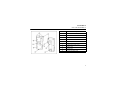
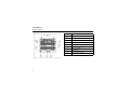
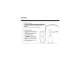
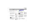
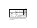
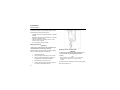
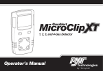
1, 2, 3, and 4-Gas Detector
iERP: 125741
D6171/0 [English]
© BW Technologies 2008. All rights reserved.
Operator’s Manual
Limited Warranty and Limitation Liability
BW Technologies LP (BW) warrants the product to be free from defects in material and workmanship under normal use and service for a period of two
years, beginning on the date of shipment to the buyer. This warranty extends only to the sale of new and unused products to the original buyer. BW’s
warranty obligation is limited, at BW’s option, to refund of the purchase price, repair or replacement of a defective product that is returned to a BW
authorized service center within the warranty period. In no event shall BW’s liability hereunder exceed the purchase price actually paid by the buyer for
the Product.
This warranty does not include:
a) fuses, disposable batteries or the routine replacement of parts due to the normal wear and teat of the product arising from use;
b) any product which in BW’s opinion, has been misused, altered, neglected or damaged, by accident or abnormal conditions of operation,
handling or use;
c) any damage or defects attributable to repair of the product by any person other than an authorized dealer, or the installation of unapproved parts
on the product; or
The obligations set forth in this warranty are conditional on:
a) property storage, installation, calibration, use, maintenance and compliance with the product manual instructions and any other applicable
recommendations of BW;
b) the buyer promptly notifying BW of any defect and, if required, promptly making the product available for correction. No goods shall be returned
to BW until receipt by the buyer of shipping instructions from BW; and
c) the right of BW to require that the buyer provide proof of purchase such as the original invoice, bill of sale or packing slip to establish that the
product is within the warranty period.
THE BUYER AGREES THAT THIS WARRANTY IS THE BUYER ’S SOLE AND EXCLUSIVE REMEDY AND IS IN LIEU OF ALL OTHER WARRANTIES, EXPRESS OR IMPLIED,
INCLUDING BUT NOT LIMITED TO ANY IMPLIED WARRANTY OF MERCHANTABILITY OR FITNESS FOR A PARTICULAR PURPOSE. BW SHALL NOT BE LIABLE FOR ANY
SPECIAL, INDIRECT, INCIDENTAL, OR BASED ON CONTRACT, TORT OR RELIANCE OR ANY OTHER THEORY.
Since some countries or states do not allow limitation of the term of an implied warranty, or exclusion or limitation of incidental or consequential
damages, the limitations and exclusions of this warranty may not apply to every buyer. If any provision of this warranty is held invalid or unenforceable
by a court of competent jurisdiction, such holding will not affect the validity or enforceability of any other provision.
Contacting BW Technologies by Honeywell
USA: 188-749-8878
Europe: +44(0) 1295 700300
Canada: 1-800-663-4164
Other countries: +1-403-248-9226
Email us at: [email protected]
Visit BW Technologies by Honeywell website at: www.gasmonitors.com
GasAlertMax XT
Introduction
Safety Information - Read First
The operator’s manual provides basic information to operate
Use the detector only as specified in this operator’s manual and
the GasAlertMax XT gas detector. For complete operating
the technical reference guide, otherwise the protection provided
instructions, refer to the GasAlertMax XT Technical Reference
by the detector may be impaired.
Guide provided on the CD-ROM. The GasAlertMax XT gas
Read the following Cautions before using the detector.
detector (“the detector”) is designed to warn of hazardous gas
levels above user-defined alarm setpoints.
The detector is a personal safety device. It is your responsibility
to respond properly to the alarm.
Note
The detector is shipped with English as the default
displayed language. Additional languages provided
are French, German, Spanish, and Portuguese. The
screens for the additional languages are displayed on
the detector and in the corresponding operator’s
manual.
a Cautions
• Warning: Substitution of components may impair Intrinsic
Safety.
• Caution: For safety reasons, this equipment must be
operated and serviced by qualified personnel only. Read
and understand the technical reference guide completely
before operating or servicing.
• Charge the detector before first-time use. BW recommends
the detector be charged after every workday.
• Calibrate the detector before first-time use and then on a
regular schedule, depending on use and sensor exposure
to poisons and contaminants. The sensors must be
calibrated regularly and at least once every 180 days
(6 months).
1
GasAlertMax XT
Operator’s Manual
• Calibrate only in a safe area that is free of hazardous gas.
• The combustible sensor is factory calibrated to 50% LEL
methane. If monitoring a different combustible gas in the
% LEL range, calibrate the sensor using the appropriate
gas.
• Only the combustible gas detection portion of this
instrument has been assessed for performance by CSA
International.
• Protect the combustible sensor from exposure to lead
compounds, silicones, and chlorinated hydrocarbons.
Although certain organic vapors (such as leaded gasoline
and halogenated hydrocarbons) may temporarily inhibit
sensor performance, in most cases, the sensor will recover
after calibration.
• BW recommends that the combustible sensor be checked
with a known concentration of calibration gas after any
exposure to contaminants/poisons such as sulfur
compounds, silicon vapors, halogenated compounds, etc.
• BW recommends to bump test the sensors before each
day’s use to confirm their ability to respond to gas by
exposing the detector to a gas concentration that exceeds
the alarm setpoints. Manually verify that the audible and
visual alarms are activated. Calibrate if the readings are not
within the specified limits.
• Caution: High off-scale LEL readings may indicate an
explosive concentration.
• Any rapid up scaling reading followed by a declining or
erratic reading may indicate a gas concentration beyond
upper scale limit, which can be hazardous.
2
• For use only in potentially explosive atmospheres where
oxygen concentrations do not exceed 20.9% (v/v).
• Extended exposure of the GasAlertMax XT to certain
concentrations of combustible gases and air may stress the
detector element that can seriously affect its performance. If
an alarm occurs due to a high concentration of combustible
gases, recalibration should be performed, or if needed, the
sensor replaced.
• The BW pump (XT-RPUMP-K1) is certified for use with the
GasAlertMax XT only.
• Warning: The lithium battery (MX-BAT01) may present a risk
of fire or chemical burn hazard if misused. Do not
disassemble, heat above 212°F (100°C), or incinerate.
• Warning: Do not use any other lithium batteries with the
GasAlertMax XT detector. Use of any other cell can cause
fire and/or explosion. To order and replace the MX-BAT01
lithium battery, contact BW Technologies by Honeywell.
• Warning: Lithium polymer cells exposed to heat at 266°F
(130°C) for 10 minutes can cause fire and/or explosion.
• Dispose of used lithium cells immediately. Do not
disassemble and do not dispose of in fire. Do not mix with
the solid waste stream. Spent batteries must be disposed of
by a qualified recycler or hazardous materials handler.
• Keep lithium cells away from children.
• All calibration cylinders must be used with a demand flow
regulator and must meet the following maximum inlet
pressure specifications:
• Disposable cylinders 0-3000 psig/70 bar
• Refillable cylinders 0-3000 psig/70 bar
GasAlertMax XT
Parts of the GasAlertMax XT
Parts of the GasAlertMax XT
Item
Description
1
Visual alarm indicators (LEDs)
2
Pump quick connector
3
Pump filter and moisture filter
4
Pushbutton
5
Alligator clip
6
Charging connector and IR interface
7
Diffusion cover locking screw (1)
8
Diffusion cover
9
Audible alarm
10
Liquid crystal display (LCD)
3
GasAlertMax XT
Operator’s Manual
Display Elements
Item
4
Description
1
Alarm condition
2
Automatically zero sensor
3
Numeric values
4
Battery life indicator
5
Pump indicator
6
Heartbeat indicator
7
Gas type identifiers
8
Gas cylinder
9
Automatically span sensor
GasAlertMax XT
Pushbutton
Pushbutton
Pushbutton
Description
• To activate the detector, press C.
• To deactivate the detector, press and hold C until the OFF countdown is complete.
• To view the date/time, TWA, STEL, and maximum (MAX) readings, press C twice rapidly. To clear
the TWA, STEL, and MAX readings, press C when the LCD displays CLEAR ALL.
C
• To initiate calibration, press and hold C while the detector performs the OFF countdown. Continue
holding C while the LCD briefly deactivates and then reactivates to begin the CAL countdown.
Release C when the CAL countdown is complete.
• To activate the backlight, press C and release.
• To acknowledge latched and pump alarms, press C.
• To acknowledge a low alarm and disable the audible alarm, press C.
The Low Alarm Acknowledge option must be enabled in Fleet Manager II.
• To acknowledge any of the Due Today alarms (calibration, bump test, block test) and disable the
audible alarm, press C.
5
GasAlertMax XT
Operator’s Manual
Connecting the Gas Cylinder to the Detector
6
GasAlertMax XT
Calibration
Calibration
a Caution
Calibrate only in a safe area that is free of hazardous gas.
Do not calibrate the detector during or immediately after
charging is complete.
Note
The maximum hose length for calibration is 3 ft. (1 m).
1. Press and hold C as the detector
performs the OFF countdown. Continue
to hold C when the detector briefly
deactivates.
2. The detector activates again and
performs the CAL countdown. Continue
to hold C until the countdown is
complete to enter calibration.
3.
flashes while the detector
zeroes all of the sensors.
If a sensor fails to auto zero, it cannot be
spanned. When auto zero is complete,
the LCD displays APPLY GAS.
4. Refer to Connecting the Gas Cylinder to
the Detector (page 7). Attach the demand
flow regulator and apply gas.
Note
The diffusion cover must be attached
to the detector to calibrate.
K flashes on the LCD. After a sufficient
amount of gas has been detected
(30 seconds), the detector beeps.
flashes while the detector
completes the span.
The LCD displays CAL DUE. Next, a
screen displays showing the number
of days remaining before calibration is
due for each sensor. Last, the LCD
displays (e.g.) CAL DUE 180 d. As
some sensors require more frequent
calibrations, the LCD displays the
earliest calibration that must be
performed.
Note
Calibration can be aborted at any time. To abort
calibration, press C. The CAL ABORTED screen
displays.
7
GasAlertMax XT
Operator’s Manual
Alarms
Refer to the following table for information about alarms and corresponding screens.
Alarm
8
Screen
Alarm
Low Alarm
• Slow siren
• Slow alternating flash
• L and target gas bar flash
• Vibrator alarm activates
TWA Alarm
• Fast siren
• Fast alternating flash
• L and target gas bar flash
• Vibrator alarm activates
High Alarm
• Fast siren
• Fast alternating flash
• L and target gas bar flash
• Vibrator alarm activates
STEL Alarm
• Fast siren
• Fast alternating flash
• L and target gas bar flash
• Vibrator alarm activates
Multi-Gas Alarm
• Alternating low and high alarm siren
and flash
• L and target gas bars flash
• Vibrator alarm activates
Over Limit (OL) Alarm
• Fast siren
• Fast alternating flash
• L and target gas bar flash
• Vibrator alarm activates
Screen
GasAlertMax XT
Alarms
Alarm
Screen
Alarm
Screen
Sensor Alarm
• ERR displays
Automatic Deactivation Alarm
• Eight beeps and eight flashes
• LOW BATTERY and L display
• Vibrator alarm temporarily activates
• OFF displays before deactivating
Low Battery Alarm
(Confidence beep disabled)
• One beep and one flash every
10 seconds
•
and L flashes
Confidence Beep
• One beep every 1-120 seconds
(user-defined in Fleet Manager II)
Heartbeat
Pump Alarm
• Two beeps and two flashes
• J and L flashes
• HIGH displays
• The vibrator alarm activates
•
flashes once every second to
verify detector is operating correctly
Note
If the Low Alarm Acknowledge option is enabled in Fleet
Manager II, the low alarm can be acknowledged and the
audible alarm deactivated by pressing C. If the alarm
escalates to a high, STEL, TWA, or multi-gas alarm, the
audible alarm reactivates.
Note
If enabled, during an alarm condition the Latched Alarms option causes the low and high gas alarms (audible, visual, and
vibrator) to persist until the alarm is acknowledged and the gas concentration is below the alarm setpoint. The audible alarm can
be temporarily deactivated for 30 seconds by pressing C, but the LCD continues to display the high peak concentration until the
alarm condition no longer exists. Enable/disable Latching Alarms in Fleet Manager II. Local regulations may require the
Latching Alarms option be enabled.
9
GasAlertMax XT
Operator’s Manual
Options Menu
The detector, IR Link adapter, and Fleet Manager II software
are required to define options. Refer to the GasAlertMax XT
Technical Reference Guide and Fleet Manager II Operator’s
Manual. For user and sensor options, refer to the following:
Device Configuration
• Startup Message Top Line: Enter a line of text to display
on the LCD during startup (maximum 25 characters).
• Startup Message Bottom Line: Enter a line of text to display on the LCD during startup (maximum 25 characters).
• Lockout on Self-Test Error (sensor alarm lock): If a
sensor fails during startup and the Lockout on Self-Test
option is enabled, Safety Lock On displays on the LCD
and the detector deactivates.
• Safe Mode: If enabled, SAFE displays continuously on the
LCD unless an alarm condition occurs.
• Confidence Beep: If enabled, the confidence beep
provides continuous confirmation that the detector is
operating correctly. To define how often the detector beeps
(every 1-120 seconds), enter the value in the
Confidence Interval field. Confidence beep is
automatically disabled during a low battery alarm.
• Latching Alarms: Enable to ensure an alarm persists
until the alarm is acknowledged and the gas concentrations are below the alarm setpoint. The audible alarm
can be temporarily deactivated for 30 seconds by
pressing C, but the LCD continues to display the high
10
•
•
•
•
•
•
•
•
peak concentration until the alarm condition no longer
exists.
Force Calibration: If enabled, the detector must be
calibrated if a sensor is overdue upon startup. User
defined (0-365 days) in the Calibration Interval field.
Cal IR Lock (must use IR device to calibrate): If enabled,
the detector automatically auto zeros, but the sensors
must be spanned using the IR Link or MicroDock II
station with Fleet Manager II.
Force Bump: If enabled, a bump test must be performed
to ensure the sensor(s) are responding correctly to the test
gas. User defined (0-365 days) in the Bump Interval field.
Location Logging: If enabled, a series of numbers
(1-999) can be entered on the detector to identify gas
wells, plants, and other areas that identify the location
where the detector is being used.
Force Block Test: If enabled, a pump block test must
be performed during the startup tests.
Datalog Interval (seconds): Define how often the
detector records a sample (every 1-120 seconds).
Confidence Interval (seconds): Define how often the
detector beeps (1-120 seconds) when the Confidence
Beep option is enabled.
Language: The LCD displays the screens in English,
Français (French), Deutsch (German), Español
(Spanish), or Português (Portuguese). Select the
language from the drop-down menu in Fleet Manager II.
GasAlertMax XT
Options Menu
Sensor Configuration (H2S, CO, LEL, and O2)
• Sensor Disabled: Enables/disables the selected sensor.
• Calibration Gas (ppm): Define the span gas concentration for each sensor. The span gas concentration must
match the span value on the gas cylinder.
• Calibration Interval (days): Define the number of days
(0-365) when the next calibration is due.
• Bump Interval (days): Define the number of days (0-365)
when the next bump test is due.
• Low Alarm (ppm): Define the low alarm setpoint for each
sensor.
• High Alarm (ppm): Define the high alarm setpoint for
each sensor.
• TWA Alarm (ppm): Define the time-weighted average
(TWA) alarm setpoint (toxic sensors only).
• STEL Alarm (ppm): Define the short-term exposure limit
(STEL) alarm setpoint (toxic sensors only).
• STEL Interval (minutes): Define the short-term exposure
limit (STEL) from 5-15 minutes (toxic sensors only).
• TWA Period hours (TWA moving average (hours): The
TWA Period option is used to define a time-weighted
moving average of accumulated gases over a period of
4-16 hours, to ensure the worker leaves the area when
the defined maximum average is accumulated.
• Correction Factor (%): Enter the compensation factors
for hydrocarbons other than methane. The factor can only
be applied if the LEL sensor has been calibrated with
methane (LEL only).
• 50% LEL = (%CH4): Enter a percentage value to display
the LEL reading as %vol., assuming a methane environment (LEL only).
• Auto-Zero on Startup: Enable/disable the detector to
automatically zero the sensor(s) during startup (H2S, CO,
LEL, and O2).
• LEL by Volume CH4: If enabled, the detector operates
assuming a methane (CH4) calibration. Enable to read and
display %CH4 values. Disable to read and display %LEL
values.
• 5% LEL Over-span: If enabled, the detector automatically
over-spans the LEL sensor by 5% LEL above the
determined span gas concentrations to ensure the span
surpasses CSA standards.
• 20.8% Base Reading: When enabled, the detector is
configured to detect 20.8% O2 as ambient air. When
disabled, the detector is configured to detect 20.9% O2
as ambient air.
• Low Alarm Acknowledge: If enabled, the audible
alarm can be temporarily disabled during a low alarm
by pressing C. The vibrator, alarm LEDs, and LCD
remain operational (toxic and LEL only).
11
GasAlertMax XT
Operator’s Manual
Maintenance
To maintain the detector in good operating condition, perform
the following basic maintenance as required.
• Calibrate, bump test, and inspect the detector on a regular
schedule.
• Maintain an operations log of all maintenance, bump tests,
calibrations, and alarm events.
• Clean the exterior with a soft damp cloth. Do not use
solvents, soaps, or polishes.
• Do not immerse the detector in liquids.
Charging the Detector
a Warning
Charge only in a safe area that is free of hazardous gas
within temperatures of 32°F-113°F (0°C-45°C).
Charge the battery after each workday. To charge the battery,
refer to the following procedures and illustration:
12
1.
Deactivate the detector.
2.
Insert the charging adapter plug into an AC outlet.
3.
Connect the charging adapter to the detector IR
receptacle. Refer to the following illustration.
4.
Allow the battery to charge for 6 hours.
5.
To reach full battery capacity, allow a new battery to
fully charge and discharge three times.
Replacing a Sensor or Sensor Filter
a Warning
To avoid personal injury and/or property damage, only
use sensors that are specifically designed for the
detector.
Note
Detectors that are configured for 1, 2, or 3 gases may
contain a dummy sensor in one of the four sensor
locations.
To replace a sensor or sensor filter, refer to the following figure,
table and procedures #1-13.
GasAlertMax XT
Maintenance
13
GasAlertMax XT
Operator’s Manual
Item
14
shell by lifting upward and tilting to the left. Both the
rear and front shell are laying flat side by side.
Description
1
Front shell
2
LEL sensor
3
PCB
4
PCB screws (2)
5
Pump
6
Rear shell
7
Machine screws (6)
8
Pump inlet
9
Pump filter (particulate)
10
Moisture filter
11
CO sensor
5.
Remove the two PCB screws.
12
H2S sensor
6.
13
O2 sensor
Lift the PCB upward and tilt to the left. Lay the PCB
(sensors facing up) onto the rear shell.
14
Sensor filter
1.
Deactivate the detector.
2.
Remove the pump inlet screw and the pump inlet.
7.
Slide the sensor(s) outward to remove (O2 lift out).
8.
Insert the new sensor(s) and replace the sensor filter.
9.
Reassemble the detector and replace the two PCB
screws.
3.
Remove the six machine screws from the rear shell.
10. Replace the six machine screws.
4.
Because the pump hose is connected to the rear
shell and front shell pump, carefully remove the rear
11. If required, replace the pump and moisture filter.
12. Replace the pump inlet and the pump inlet screw.
GasAlertMax XT
Specifications
13. Activate the detector and then calibrate the new
sensor(s). Refer to Calibration.
Specifications
Instrument dimensions: 13.1 x 7.0 x 5.2 cm
(5.1 x 2.8 x 2.0 in.)
Weight: 300 g (10.6 oz.)
Operating temperature: -20°C to +50°C (-4°F to +122°F)
Storage temperature: -40°C to +60°C (-40°F to +140°F)
Alarm conditions: TWA alarm, STEL alarm, low alarm, high
alarm, multi-gas alarm, over limit (OL) alarm, low battery alarm,
confidence beep, automatic deactivation alarm, and pump
alarm
Audible alarm: 95 dB+ at 30 cm variable pulsed beeper with
full battery charge
Visual alarm: Red light-emitting diodes (LEDs)
Display: Alphanumeric liquid crystal display (LCD)
Operating humidity: 10% to 100% relative humidity
(non-condensing)
Backlight: Activates upon startup and when the pushbutton is
pressed; deactivates after 10 seconds. Also activates during an
alarm condition and remains lit until alarm ceases
Dust and moisture ingress: IP66/67
Self-test: Initiated at activation and tests continuously
Alarm setpoints: May vary by region and are user-defined
Calibration: Automatic zero and automatic span
Detection range:
User field options: Startup message, lockout on self-test error,
safe mode, confidence beep, latching alarms, force calibration,
cal IR lock, force bump, location logging, force block test,
set datalog interval, set confidence interval, language selection
H2S: 0 - 200 ppm (1 ppm increments)
CO: 0 - 1000 ppm (1 ppm increments)
O2: 0 - 30.0% vol. (0.1% vol. increments)
Combustible (LEL): 0 - 100% (1% LEL increments) or
0 - 5.0% v/v methane
Sensor type:
H2S, CO, O2: Single plug-in electrochemical cell
Combustibles: Plug-in catalytic bead
O2 measuring principle: Capillary controlled concentration
sensor
Sensor options: Sensor enable/disable, set span calibration
values, set calibration interval, set bump interval, set alarm
setpoints, set STEL interval, set TWA period, auto zero at
startup enable/disable, 5% over span, low alarm acknowledge,
oxygen measurement, and combustible gas measurement
Battery operating time:
One rechargeable lithium polymer: 13 hours (typical)
15
GasAlertMax XT
Operator’s Manual
Year of manufacture: The detector's year of manufacture is
determined from the serial number. The second and third number after the second letter determines the year of manufacture.
E.g., MA 108-000001 = 2008 year of manufacture
Approved batteries:
North America
Approved batteries for GasAlertMax XT product:
Lithium-ion polymer battery as per standards EN50020, UL913,
C22.2 No. 157
Rechargeable battery (MX-BAT01)
Lithium polymer -20°C
Ta
+50°C
Temperature code
T4
Battery charger: charging adapter
First-time charge: 6 hours
Normal charge: 6 hours
Warranty: 2 years including sensors
Approvals:
Approved by CSA to both U.S. and Canadian Standards
CAN/CSA C22.2 No. 157 and C22.2 152
ANS/UL - 913 and ANSI/ISA - S12.13 Part 1
Class I, Division 1, Group A, B, C, and D
CSA
ATEX
CE 0539 g II 1 G Ga Ex ia IIC T4
IECEx
16
KEMA 08 ATEX 0001
Ga Ex ia IIC T4
This equipment has been tested and found to comply with the
limits for a Class B digital device, pursuant to Part 15 of the
FCC Rules and ICES-003 Canadian EMI requirements. These
limits are designed to provide reasonable protection against
harmful interference in a residential installation. This equipment
generates, uses and can radiate radio frequency energy and, if
not installed and used in accordance with the instructions, may
cause harmful interference to radio communications. However,
there is no guarantee that interference will not occur in a particular installation. If this equipment does cause harmful interference to radio or television reception, which can be
determined by turning the equipment off and on, the user is
encouraged to try to correct the interference by one or more of
the following measures:
• Reorient or relocate the receiving antenna.
• Increase the separation between the equipment and
receiver.
• Connect the equipment into an outlet on a circuit different
from that to which the receiver is connected.
• Consult the dealer or an experienced radio/TV technician
for help.
Corporate Headquarters
Calgary, Alberta
127324
GasAlertMax XT
Errata Card
Regulators Used For the GasAlertMax XT Detector
Calibrations and bump tests can be performed
using either of the following regulators:
Replacement Parts and Accessories
Model No.
• 0.5 l/min regulator
• Demand flow regulator
3¾ in.
Description
Qty
REG-0.5
0.5 l/min regulator
1
REG-DF-1
Demand flow regulator
1
a Warning
Calibration cylinders that are used with a
demand flow regulator must meet the
following maximum inlet pressure
specifications:
• Disposable cylinders 0-1000 psig/70 bar
• Refillable cylinders 0-3000 psig/207 bar
5½ in.
Printing Information
iERP #
127324
Size:
3¾ x 5½ inches
Stock:
80 lb cougar cover card stock
Print Color:
Black
DTN:
Temporary (no DTN)
Language:
English
1, 2, 3, and 4-Gas Detector
iERP: 125741
D6171/0 [English]
© BW Technologies 2008. All rights reserved.
Operator’s Manual