1
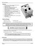
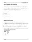
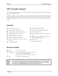
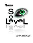
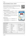
Phason SSV-DC user manual The SSV-DC has a 0 to 10 VDC signal output and a disconnect relay that allows you to easily and effectively control up to 10 variable frequency drives, slave units, modulating valves, or other equipment that requires a DC signal. The knob allows you to easily move between and adjust settings, while the programming lights show which settings you are editing. The two LED displays show temperatures, signal output, programming information, and alarm codes. Features Automatic temperature-based control with extended range: -13 to 125°F (-25 to 51°C) Variable 0 to 10 V output Capacity for up to 10 devices Disconnect relay for start/stop signal Alarm relay (for external alarm system or siren) Three-second full-power-turn-on to minimize fan ice-up Three-character LED display Status and programming LEDs Error code display Power-failure protection (will not lose settings) Six-foot temperature probe, extendable to 500 feet Rugged NEMA 4X enclosure (corrosion resistant, water resistant, and fire retardant) cCSAus approval Limited warranty, two years Electrical ratings Input power 120/230 VAC, 50/60 Hz Signal output 0 to 10 VDC, 2K Ω load Disconnect relay 5A at 250 VAC; 5A at 30 VDC, resistive load 2A at 250 VAC; 2A at 30 VDC, inductive load Alarm relay 0.4 A at 125 VAC; 2 A at 30 VDC, resistive load 0.2 A at 125 VAC; 1 A at 30 VDC, inductive load 32740003 1 SSV-DC user manual Phason Common applications The SSV-DC has applications in livestock, greenhouse, and light industrial buildings. Ventilation systems that use three-phase motors often use a variable frequency drive (VFD). The SSV-DC can control VFDs with its 0 to 10 VDC output. For applications that use single-phase, permanent split capacitor (PSC) motors, the SSV-DC can control the motors using a triac-based slave with DC input, such the Phason FanDRIVE. The SSV-DC can also control electronically commutated motors (ECMs) using its 0 to 10 VDC output. Installing the SSV-DC 1 2 3 6 5 4 5 6 Power terminal: connect the incoming power (120/230 VAC, 50/60 Hz) to this terminal. Temperature terminal: connect the temperature probe to this terminal. 0 to 10 terminal: connect variable frequency drives, modulating valves, or other equipment that requires a 0 to 10 VDC input signal. Disconnect terminal: if the equipment connected to #3 requires a disconnect switch, connected to this terminal. Alarm terminal: connect an external alarm system or alarm siren to this terminal. Temperature selector: place the jumper on the top two pins for Celsius, or on the bottom two pins for Fahrenheit. 1 2 3 4 Before connecting the incoming power, switch OFF the power at the source. Do not switch ON the power until you have finished all wiring and verified all equipment is properly connected and free of obstructions. Replace damaged probes as soon as possible. If there is no probe present or working properly, the SSV-DC displays either p d or p s and the 0 to 10 V output operates at 20%. 2 2015-11-27 Phason SSV-DC user manual Mounting the SSV-DC 1. Loosen the screws from the front cover and then lift it off. 2. Mount the enclosure to a wall using the four screws provided with the control. Insert the screws into the holes in the mounting tabs at the top and bottom of the enclosure and then tighten. Selecting the temperature unit The SSV-DC can operate in either degrees Fahrenheit (°F) or degrees Celsius (°C), but not both at the same time. The default is Fahrenheit. Locate the UNITS pins in the top-left corner of the circuit board. For Celsius, place the jumper on the top two pins. For Fahrenheit, place the jumper on the bottom two pins Connecting equipment to the SSV-DC The SSV-DC has a 0 to 10 VDC signal output and disconnect relay for controlling variable frequency drives, modulating valves, or other equipment requiring a 0 to 10 V DC signal. The disconnect relay is not for controlling fans, heaters, or other equipment. When the 0 to 10 VDC signal output is at 0, the relay sends a stop signal (closes the disconnect relay) to the equipment you are controlling with the variable output. You can connect up to 10 devices (variable frequency drives, modulating valves, or similar equipment) to a single SSV-DC. Connect the equipment as shown below. 32740003 3 SSV-DC user manual Phason Connecting an alarm system An alarm system can be a siren, an alarm panel, or an auto-dialer. See your alarm siren’s installation guide for installation instructions and information about the type of system, normally open or normally closed. The descriptions for the alarm terminal are as follows: CC–common connection, CA–closed on alarm, OA–open on alarm. If you are connecting the alarm system to a network of controls and your system uses a normally open connection (closes on alarm), connect the system as shown in the normally open diagram. Join all the common (CC) connections together and all the closed-on-alarm (CA) connections together. The SSV-DC alarm relays must be in parallel with each other so any control can trigger the alarm system when an alarm condition occurs. If you are connecting the alarm system to a network of controls and your system uses a normally closed connection (opens on alarm), connect the system as shown in the normally closed diagram. Join the alarm relays in a continuous loop. The SSV-DC alarm relays must be in series with each other so any control can trigger the alarm system when an alarm condition occurs. Normally closed system (open on alarm) 4 Normally open system (closed on alarm) 2015-11-27 Phason SSV-DC user manual Programming the SSV-DC If you are connecting a variable frequency drive (VFD) that has a programmable startup ramp and want to take advantage of the deicing feature (three-second fullpower-turn-on), you must set the ramp duration as short as possible, preferably less than 0.1sec. How the SSV-DC operates When the temperature is below the idle range, the fan (in other words, DC output) is off. When the temperature is below the low alarm, the alarm relay activates, the Alarm LED lights up, and the display flashes between the temperature and Lo . When the temperature reaches the idle range, the fan runs at the idle speed. The fan continues to run at the idle speed until the temperature rises to the set point. When the temperature is between the set point and differential, fan speed increases or decreases proportionally with the temperature. When the temperature is at or above the differential, the fan runs at full speed. When the temperature is above the high alarm, the alarm relay activates, the Alarm LED lights up, and the display flashes between the temperature and HI . The alarm relay activates when the temperature is above the temperature. High alarm temperature The fan runs at full speed. Differential temperature Fan speed increases as the temperature rises, or decreases as the temperature falls. Set point temperature The fan runs at . The temperature band between the idle range temperature and the is sometimes called the “ ”. Idle range temperature The fan is off when the temperature is below the temperature. Idle speed Fan speed The alarm relay activates when the temperature is below the 32740003 temperature. Low alarm temperature 5 SSV-DC user manual Phason To program the control 1. Press the encoder knob until P a r displays. 2. Turn the knob clockwise until the LED for the setting you want to program is lit. 3. Press the knob to select the setting. The control enters edit mode and the LED for the setting flashes. 4. Turn the knob clockwise to increase, or counterclockwise to decrease the value. 5. Press the knob to save the setting and leave edit mode. The display shows p a r . 6. Repeat steps 2 to 5 for each setting you want to program. 7. When finished, press the knob to return to the temperature display. Factory defaults Setting Stage 1 idle speed (%) Stage 1 idle range (°F/°C) Stage 1 set point (°F/°C) Stage 1 differential (°F/°C) High temperature alarm (°F/°C) Low temperature alarm (°F/°C) Default 20 80.0 85.0 86.5 95.0 80.0 Range/options 0 to 100 % -13 to 125°F (-25 to 51°C) -13 to 125°F (-25 to 51°C) -13 to 125°F (-25 to 51°C) Low temp alarm to 125°F (51°C) -13°F (-25°C) to high temp alarm Using manual mode Manual mode allows you to override the automatic settings. Manual mode is useful for testing equipment or other special situations. 1. Press the encoder knob until P a r displays. 2. Turn the knob clockwise until the LED for Alarm is lit. 3. Press the knob. The control enters manual mode and the LED for Alarm flashes. 4. Turn the knob clockwise to increase, or counterclockwise to decrease the output. 5. Press the knob to leave manual mode. The display shows p a r . 6. Press the knob to return to the temperature display. 6 2015-11-27 Phason SSV-DC user manual Troubleshooting When there is an alarm condition, the Alarm LED flashes, an error code displays, and the alarm relay activates. When the condition goes away, the alarm relay deactivates and the Alarm LED switches off, but the message continues to display until acknowledged by pressing the knob. When there is a probe damage or short condition, the control operates at 20%. If you are having a problem using the SSV-DC, check if the problem is described in the following table, and then follow the directions for correcting the problem. Problem/alarm code Hi Lo pd ps Possible cause High temperature alarm Low temperature alarm Probe damage alarm Probe short alarm Power supply components blown out, burn marks on boards and components Motors and fans slow down or stop No power/display Display showing unusually high or low temperature 32740003 Possible solution Ambient temperature is too high Increase ventilation/cooling. High temperature alarm setting is Increase the high temperature alarm setting. For more information, read Programming the too low SSV-DC on page 5. Ambient temperature is too low Decrease ventilation/cooling, increase heating. Low temperature alarm setting is Decrease the low temperature alarm setting. too high For more information, read Programming the SSV-DC on page 5. The temperature probe is damaged, Check the wire between the control and the missing, or the connecting wire is probe. Wire damage can cause the alarm. broken. The temperature probe Replace or reconnect the temperature probe. circuit is open. The control should recover automatically. The temperature probe is damaged. Check the wire between the control and the The temperature probe circuit is probe. Wire damage can cause the alarm. closed. Replace the temperature probe. The control should recover automatically. Power surge, brownout, or power outage A circuit breaker at service panel is off or tripped. Incorrect incoming power wiring The probe is not a Phason probe. The extension cable connected to the temperature probe is providing a poor connection Damaged probe Avoid the problem in future by providing proper voltage and surge protection for the control. Reset the circuit breaker. Correct the wiring. Remove the probe and then install a Phason probe. Check the extension cable connection and resolder it if necessary. Replace the temperature probe. 7 SSV-DC user manual Phason Problem/alarm code Variable fan runs at maximum Variable fan not running Possible cause Possible solution Incorrect wiring Idle speed is too high Incorrect wiring Idle speed setting is too low Idle range temperature setting is too high Temperature set point is above room temperature Correct the wiring. For more information, read Connecting equipment to the SSV-DC on page 3. Decrease the idle speed setting. For more information, read Programming the SSV-DC on page 5. Correct the wiring. For more information, read Connecting equipment to the SSV-DC on page 3. Increase the idle speed setting. For more information, read Programming the SSV-DC on page 5. Decrease the idle range temperature setting. For more information, read Programming the SSV-DC on page 5. Adjust the set point to the desired temperature. For more information, read Programming the SSV-DC on page 5. Switch on the power. Replace the equipment. Reset the breaker. No power to the fan Faulty fan Circuit breaker open Service and technical support Phason will be happy to answer all technical questions that will help you use your SSV-DC. Before contacting Phason: Read the manual for information about the feature with which you are having trouble. If the control is not operating properly, read Troubleshooting on page 7, and then follow the directions to correct the problem. Phason controls are designed and manufactured to provide reliable performance, but they are not guaranteed to be 100 percent free of defects. Even reliable products can experience occasional failures and the user should recognize this possibility. If Phason products are used in a life-support ventilation system where failure could result in loss or injury, the user should provide adequate back up ventilation, supplementary natural ventilation, or an independent failure-alarm system. The user’s lack of such precautions acknowledges their willingness to accept the risk of such loss or injury. Phason Inc. 2 Terracon Place Winnipeg, Manitoba, Canada R2J 4G7 8 Phone: Fax: 204-233-1400 204-233-3252 E-mail: Web site: [email protected] www.phason.ca 2015-11-27