1
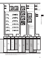
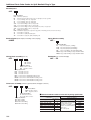
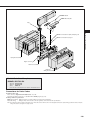
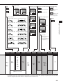
CAD drawing data catalog
is available.
VALVES GENERAL CATALOG
INDEX
Features
Handling Instructions and Precautions
Disassembly Diagram of Split Manifold
Detailed Diagram of Wiring Block Internal Connections
Serial Transmission Block Specifications
Operating Principles and Symbols
Order Codes
Pin Locations by Wiring Specification
Cable Assemblies by Wiring Specification
Pin Numbers and Corresponding Solenoids
Specifications
Dimensions of Single Valve Unit
Dimensions of Monoblock Manifold
Dimensions of Split Manifold Non-Plug-in Type
Dimensions of Split Manifold Plug-in Type
Dimensions of Serial Transmission Type
Caution
175
177
181
184
185
186
188
205
206
208
213
216
218
219
220
227
Before use, be sure to read the “Safety Precautions” on p. 31.
174
SOLENOID VALVES JA SERIES
SOLENOID VALVES
SERIES
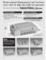
We have achieved “Miniaturization” and “Low Power
3-port valves for high value-added new generation
New Valves for the New Century
Solenoid Valves
Thin and compact
Series
Low power consumption
●Valve width of only 10.5 mm [0.41in.] achieves a
thin and compact size valve, enabling space
saving in equipment design.
2
●Effective area : 3.5mm〔
Cv: 0.19〕
Suitable for operating up toφ40 [1 1/2in.] bore
size cylinders.
●Standard: 0.5W (21mA at DC24V, 42mA at DC12V)
●Low current type: 0.25W (10.5mA current at DC24V) Note
Note: When using power saving circuit
(Starting current is 21mA.)
Negative common is available
●Positive or negative common is selectable on
connector side using the same valve type.
(Excluding serial transmission type)
Manifold
height
50mm
[2in.]
Photo shows split type manifold plugin type with flat cable and 20-pin
connector with built-in muffler on
exhaust port in the piping block.
Wide
Product Range
Select from a choice of five types
for customers’ applications.
Split Manifold Non-Plug-in Type
175
Sub-base
Monoblock Manifold Type
Split Manifold Plug-in Type
Serial Transmission Type
Consumption” as well as the addition of Tandem
valves.
Tandem 3-port, 4-position valve
4(A) side 2(B) side
Symbol
Normally Normally
closed
closed
(NC)
(NC)
12
(SB)
Normally Normally
open
open
(NO)
(NO)
12
(SB)
Normally Normally
open
closed
(NO)
(NC)
12
(SB)
(
2 B)
(
4 A)
14
(SA)
(
3 R2)(
5 R1)
1 P) (
(
2 B)
(
4 A)
14
(SA)
(
3 R2)(
5 R1)
1 P) (
(
2 B)
(
4 A)
14
(SA)
(
3 R2)(
5 R1)
1 P) (
Wire saving is possible
●Common terminal pre-wired type (available for monoblock manifold and split manifold non-plug-in type)
●Flat cable connector and D-sub connector (available for split manifold plug-in type)
●Conforming to serial transmission (Conforming to CC-Link, DeviceNet, and CompoBus/S)
Common terminal prewired plug connector
Flat cable connector
on top surfaceNote
Flat cable connector
on side surfaceNote
D-sub connector on
top surfaceNote
D-sub connector on
side surfaceNote
Serial transmission type
Note: Connector mounting direction can be changed. But in the -D370U, D-sub connector on top surface is only available.
Back pressure prevention valve (optional)
This prevents erratic operation occuring from back
pressure, in such as single acting cylinder applications.
Supply and exhaust piping block
You can select either quick fitting type or built-in muffler type for
exhaust port except for monoblock type manifold.
Back pressure
prevention valve
Withφ8mm quick fitting type
With 1/4 inch quick fitting type
With 3/8 inch quick fitting type
Built-in muffler type
Individual air supply spacer (optional)
By installing dedicated air
supply spacer between the
manifold and the valve,
individual air supply is
possible.
Individual air supply spacer
176
SOLENOID VALVES JA SERIES
●Two 3-port valve functions in one valve body.
Model
●The same 3-port valve operation with half the number of
the current valves. Two 3-port valves can be operated JA10□AA
independently in the same valve.
●3 valve types are available.
JA10□AA:Normally closed & Normally closed type JA10□AB
JA10□AB:Normally open & Normally open type
JA10□AC:Normally closed & Normally open type
JA10□AC
●The same valve operation is possible as 3-position
valve.
JA10□AA works as exhaust center valve
JA10□AB works as pressure center valve
Handling Instructions and Precautions
Solenoid
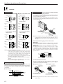
Wiring instructions (When using as a single unit or non-plug-in type manifold)
Internal circuit
● Positive common(DC24V, DC12V)
● Negative common(DC24V, DC12V)
Single solenoid
Single solenoid
(Inside connector)
Lead wire
(+)
Red A
(Inside connector)
Lead wire
(+)
Red A
(Red) 14
(SA)
Lead wire
Black A(−)
(Red) 14
(SA)
Lead wire
Black A(−)
Double solenoid
1. Attaching and removing plug connector
Use fingers to insert the connector into the pin, push it in until the
lever claw latches onto the protruded section of the connector housing, and complete the connection.
To remove the connector, squeeze the lever along with the connector, lift the lever claw up from the protruded section of the connector
housing, and pull it out.
Double solenoid
(Inside connector)
(Inside connector)
Lead wire
(+)
Red A
Lead wire
(−)
Black A
(Red)
(Red) 14
(SA)
14
(SA)
Lead wire
Red COM(+)
Lead wire
COM(−)
Black
(Green)
12
(SB)
Lead wire
(−)
White B
12
(SB)
(Green)
Lead wire
White B(+)
Lever
Housing
〈Low current type〉
(DC24V)
Protruded section
〈Low current type〉
(DC24V)
Single solenoid
Pin
Single solenoid
Plug connector
Contact
(Inside connector)
Lead wire
(+)
Red A
Timer
circuit
Lead wire
Black A(−)
14
(SA)
(Red)
(Inside connector)
Lead wire
(+)
Red A
Lead wire
Black A(−)
Double solenoid
(Inside connector)
Lead wire
(−)
Black A
(Red)
14
(SA)
(Red)
Caution: When removing the connector, confirm that the lever claw is completely disengaged from the protruded section before pulling out. The housing may be damaged if it is pulled out while engaging with the protruded section.
Double solenoid
2. Attaching and removing plug connector and contact
(Inside connector)
Lead wire
(+)
Red A
Timer
circuit
Timer
circuit
14
(SA)
14
(SA)
(Red)
Lead wire
COM(−)
Black
Lead wire
COM(+)
Red
Timer
circuit
Lead wire
(−)
White B
Lead wire
Timer
circuit
12
(SB)
(Green)
(Green)
Lead wire
White B(+)
Timer
circuit
12
(SB)
Cautions: 1. Do not apply megger between the pins.
2. Leakage current inside the circuit could result in failure of the solenoid
valve to return to the rest position or in other erratic operation. Always
use it at less than the allowable leakage current shown in the solenoid
specifications on p.213. If circuit conditions, etc. cause the leakage current to exceed the maximum allowable leakage current, consult us.
3. For the double solenoid specification, avoid energizing both solenoids
simultaneously. (Excluding the tandem 3-port valve)
4. The standard housing type is colored blue, while the low current type is
light blue.
5. The low current type will not activate if the power supply voltage is
raised slowly. Always apply the appropriate voltage.
Operating principles of low current type
The low current type uses a timer circuit, as shown above, that
achieves power savings by switching to holding operations mode after
a certain period of time to operate at about 1/2 of the starting power
consumption.
●Attaching
Insert the contact with lead wire into a plug connector □ hole until
the contact hook latches on and is secured to the plug connector.
Confirm that the lead wire cannot be easily pulled out. (See below)
●Removing
To remove it, insert a tool with a fine tip (such as a small
screwdriver) into the rectangular hole on the side of the plug
connector to push up on the hook, and then pull out the lead wire.
When re-using the contacts, restore the hook back so that they
spread outward.
Plug connector
Hook
Contact
Indication of polarity(DC)
Lead wire
3. Common terminal and short bar
A short bar is attached to the plug connector to ensure that the
wiring of solenoid A and B become positive common or negative
common. Do not remove the short bar.
● For positive common
● For negative common
Plug connector
(Gray)
Plug connector
(Ivory)
● Power waveform
Power
consumption
Solenoid
valves
ON
Short bar
0.5W
Reduced power
consumption
0.25W
Start-up time(50ms)
177
OFF
Contact (without lead wire)
Short bar
Contact (without lead wire)
Caution: The plug connectors for positive common and negative common
differ in shape.
4. Crimping of connecting lead wire and contact
Insulation crimp holder
For common connector assembly, order the common connector
assemblies listed below.
● For positive common
A type Model:JAZ-PA□※
Red : Common wire(+)
Black : A side(−)
White : B side(−)
(Insert when using as double solenoid)
Exposed wire 4mm [0.16in.]
Exposed wire crimping section
Contact
Lead wire
Applicable wire
AWG#24∼#30
Hook
Insulation
(Maximum outer diameter:φ1.5 [0.06in.])
Cautions: 1. Do not pull the lead wire too hard.
2. Always use a dedicated tool for crimping of connecting lead wire
and contact.
Contact: Model 706312-2MK Manufactured by Sumiko Tech, Inc.
Crimping tool: Model F1 (For 706312-2MK) Manufactured by
Sumiko Tech, Inc.
5. Common connector assembly for manifold
Using common connector assembly for the solenoid valve for manifold provides common wiring for all solenoid valves and greatly
reduces wiring work.
The common connector types are determined by the location
viewed from the lead wire side, the right end one is A type, the left
end one is C type, and all others are B type. (See below)
B type Model:JAZ-PB□※
Red : Common wire(+)
Black : A side(−)
White : B side(−)
(Insert when using as double solenoid)
C type Model:JAZ-PC□※
Red
Black
White
Red
: Common wire(+)
: A side(−)
: B side(−)
(Insert when using as double solenoid)
: Common wire(+)
※Lead wire length Blank : 300mm[11.8in.]
3 : 3000mm[118in.]
● For negative common
A type Model:JAZ-MA□※
Black : Common wire(−)
Red : A side(+)
White : B side(+)
(Insert when using as double solenoid)
B type Model:JAZ-MB□※
Black : Common wire(−)
Red : A side(+)
White : B side(+)
(Insert when using as double solenoid)
● For positive common
Single solenoid valve
C type Model:JAZ-MC□※
Black
Red
White
Black
Double solenoid valve
B type
A type
: Common wire(−)
: A side(+)
: B side(+)
(Insert when using as double solenoid)
: Common wire(−)
※Lead wire length Blank : 300mm[11.8in.]
3 : 3000mm[118in.]
Common wire(+)
(Red)
Common wire(+)
(Red)
C type
)B
● For negative common
A
BA
A
)
(―
A
Common wire(+)
(Red)
Manual override
Manual override (Blank: Non-locking type, -83: Locking protruding type)
To lock the locking protruding type, use a small screwdriver to push down on the
manual override all the way and turn it clockwise 90 degrees. When locked, turning the manual override 90 degrees in the counterclockwise direction releases a
spring on the manual override, returns it to the original position, and releases the
lock. When the manual override is not turned, this type acts just like the non-locking type, like the valve energizing status as long as the manual override is
pushed down, and returning to the rest position upon release.
(―
Single solenoid valve
Double solenoid valve
SB side
manual override
(Green)
B type
A type
SA side
manual override
(Pink)
Common wire(―)
(Black)
Common wire(―)
(Black)
C type
(+
)B
A
BA
A
+
A(
)
Common wire(―)
(Black)
PUSH
Non-locking type
Locking protruding type
Cautions: 1. The JA series valves are pilot type solenoid valves. As a result, the manual
override cannot switch the main valve without air supplied from the 1(P) port.
2. Always release the lock on the locking protruding type manual overrides
before commencing normal operation.
3. Do not attempt to operate the manual override with a pin or other object
having an extremely fine tip. It could damage the manual override button.
178
SOLENOID VALVES JA SERIES
To crimp lead wires into contacts, strip off 4mm [0.16in.] of the insulation from the end of the lead wire, insert it into the contact, and
crimp it. Be sure to avoid catching the insulation on the exposed
wire crimping section.
Handling Instructions and Precautions
Manifold
Fittings
Replacement of fittings
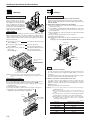
Installing and removing valves
1. Replacement of delivery port fittings for monoblock manifolds
To remove the valve body from the subbase or manifold, loosen the valve
mounting screws (2 places), and pull the
valve straight out in the direction of the
arrow (see illustration to the right). For
mounting, perform the same procedure in
reverse. The recommended tightening
torque for the valve mounting screw is
17.6N・cm {1.8kgf・cm} [1.56in・lbf].
Port isolator
In the split manifold, inserting port isolators into the 1(P), 3(R2), and
5(R1) ports between each of the stations isolates the air path between
stations equipped with port isolators and stations with smaller station
numbers. Care should be taken, however, that a piping block must be
placed on both ends.
● Port isolator for 1(P) port
(Model: JAZ-S1)
Can supply two different pressures.
● Port isolator for 3(R2) and 5(R1) ports
(Model: JAZ-S3)
Can isolate exhaust air.
(prevents exhaust interference)
● Port isolator for 1(P), 3(R2) and
5(R1) ports
(Model: JAZ-SA)
Can supply two different pressures,
and can isolate exhaust air.
(prevents exhaust interference)
Remove the fitting to be replaced, attach a gasket to the new fitting, and tighten.
Tightening torque:196N・cm{20kgf・cm} [17.3in・lbf] (Fitting single unit model:
JAZ-J4K, JAZ-J6K)
2. Replacement of delivery port fittings for split manifolds
q Loosen the mounting screws of the valve for the fitting to be replaced,
and remove the valve.
w Use a flatblade screwdriver (blade width 2mm [0.08in.]) to remove the
stopper pin holding the fitting to the valve base from the valve base
hook, and pull it out.
e Remove the fitting to be replaced, and push in and attach the new fitting
as far as it will go.
r Push in the stopper pin until it hooks onto the valve base.
t Mount the valve back into place.
Note: Ensure that the fitting and the stopper pin mounting in place are firmly
secured.
(Fitting single unit model: JAZ-J4, JAZ-J6, JAZ-J1/8, JAZ-J1/4 )
Stopper pin
Hook
Fitting
Release ring
-S1:Port isolator for
1(P) port
Tube
1. Attaching and removing tubes
-S3:Port isolators for 3(R2)
and 5(R1) ports
Caution: Mounting port isolators requires disassembly and re-assembly of manifolds.
See the disassembly diagram, unit adding procedure, and cautions on p.181
∼183.
For tube connection, insert an appropriate size tube unitl it comes
into contact with the tube stopper, and lightly pull it to check the
connection.
For tube removal, push the tube against the tube stopper, then push
the release ring and at the same time pull the tube out.
2. Either a nylon tube or urethane tube can be used.
Replacement of muffler
When using a piping block with built-in muffler, follow the below procedure to replace the muffler. (Muffler single unit model: JAZ-M)
q Remove the mounting screws (2 pcs.) holding the cover on top of
the piping block.
w Remove the muffler to be replaced.
e Insert the new muffler so that it reaches the bottom of the groove.
r Reinstall the cover, and tighten the mounting screws.
Tightening torque: 49N・cm {5kgf・cm} [4.3in・lbf]
Cover
Muffler(JAZ-M)
Use tubes with an outer diameter tolerance within ±0.1mm
[±0.004in.] of the nominal diameter, and ensure the ovalness
(difference between large diameter and small diameter) is 0.2mm
[0.008in.] or less.
(Using a Koganei tube is recommended.)
Cautions: 1. Do not use extra-soft tubes since their pull-out strength is
significantly reduced.
2. Only use tubes without scratches on the outer surfaces. If a
scratch occurs during repeated use, cut off the scratched
section.
3. Do not bend the tube excessively near the fittings.The minimum
bending radius for nylon tubes is as shown in the table below.
4. When attaching or removing tubes, always stop the air supply.
In addition, always confirm that air has been completely
exhausted from the manifold.
mm [in.]
179
Tube size
Minimum bending radius
φ4[0.157in.]
20 [0.8]
φ6[0.236in.]
30 [1.2]
φ8[0.315in.]
50 [2.0]
1/8 in.
20 [0.8]
1/4 in.
30 [1.2]
3/8 in.
50 [2.0]
Mounting the back pressure prevention valve on the manifold enables
users to prevent erratic cylinder operation due to exhaust from other
valves. This is particularly effective when using single acting cylinders
or exhaust center valves. Care should be taken, however, that the
effective OUT-EXH area is reduced to 2.5mm2〔Cv:0.14〕when using
the back pressure prevention valve. In addition, do not let the manifold’s exhaust port throttle the exhaust air, since the back pressure
prevention valve allows leaks in back pressure. When mounting additional back pressure prevention valves to existing units, observe the
following items:
q Loosen the valve mounting screws used to install the back pressure
prevention valve, and remove the valve.
w For the monoblock manifold, temporarily remove the gasket from
between the valve and manifold, insert the back pressure prevention valve into the exhaust port, place the gasket, and then mount
the valve.
Precautions for use of individual air supply spacer
By mounting an individual air supply spacer on the manifold, air supply can be
provided individually on the unit. Care should be taken that when spacers are
used, the effective area is reduced by about 20%. When mounting additional
spacers to existing units, observe the following items.
●Procedure for mounting spacers
q Loosen the valve mounting screws for the added individual air supply spacer,
and remove the valve.
w Install the gaskets provided with the individual air supply spacer, and use the
mounting screws provided to mount the valve and spacer on the manifold.
(See below)
For plug-in type, also install the provided connector Ass’y. Tightening torque of
the mounting screw: 17.6N・cm {1.8kgf・cm} [1.56in・lbf]
(Individual air supply spacer single unit model: JAZ-NPM, JAZ-PPM)
Mounting screw
Mounting screw
(Illustration shows the split manifold plug-in type)
Gasket
Gasket
Individual air
supply spacer
Back pressure
prevention valve
Connector Ass’y
●Dimensions mm [in.]
For non-plug-in type
For plug-in type
JAZ-NPM
JAZ-PPM
M5X0.8
1
Back pressure
prevention valve
1
Dedicated gasket
9[0.354] 10[0.394]
M5X0.8
42.5[1.673]
Connector Ass’y
42.5[1.673]
14.8[0.583]
15.4[0.606] 10[0.394]
Mounting screw
9[0.354] 10[0.394]
For the split type manifold, remove the gasket from between the
valve and manifold, insert the back pressure prevention valve into
the exhaust port, mount the dedicated gasket provided, and then
install the valve.
Remark: When attaching fittings to the Individual air supply spacer, use the recommended fittings shown below.
TSH4-M5M, TSH4-M5, TSH6-M5M, TS4-M50, TS4-M5M
However, only the TSH4-M5M can be attached to JA10A7, A8, and A9
(3-position valve).
Changing the direction of the connector bracket
Change the connector from upward facing to side facing by removing the
wiring block mounting screws, setting the connector bracket in the position
shown in the illustration, and then turning the connector 90 degrees so that it
faces to the outside.
Connector bracket
Tightening torque of mounting screw : 17.6N・cm {1.8kgf・cm}
[1.56in・lbf]
〔Back pressure prevention valve single unit model: JAZ-E1 (for
monoblock type), JAZ-E2 (for split type)〕
Tightening torque of mounting screw:
49N・cm {5kgf・cm} [4.3in・lbf]
Mounting screw
Caution: The direction of the -D370U connector cannot be changed, D-sub on
top is the only option.
180
SOLENOID VALVES JA SERIES
Precautions for use of back pressure prevention valve
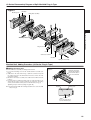
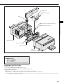
JA Series Disassembly Diagram of Split Manifold Non-Plug-in Type
Figure 1
Mounting screw
End block
Piping block assembly
Valve base assembly
End block
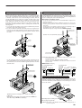
Manifold Unit Adding Procedure (JA Series Non-Plug-in Type)
■Adding valve base unit
Use the valve base assembly for adding valve base units.
q Loosen the mounting screw on the end block until it can slide (see
Fig.1).
w Disconnect the link between the valve base assembly’s bases
where the new unit is to be added.
e Mount the valve base assembly to be added on the DIN rail shown
in Fig. 2.
r Press the bases together from both sides to ensure that there is no
gap between them, and then tighten the end block mounting
screws, and install the units in place on the DIN rail (see Fig. 3).
Tightening torque: 147N・cm {15kgf・cm} [13in・lbf]
Note: Confirm that the DIN rail mounting bracket hooks secure the DIN
rail (see Fig. 3).
Figure 2
First let the hook latch
onto this side, and then
press down the base to
secure it onto the DIN
rail.
Figure 3
End block
Mounting screw
【 Caution】
● Always cut off the power and air supply before working. In addition,
always confirm that air has been completely exhausted from the
manifold.
● Care should be exercised not to become trapped or lose gaskets.
● Before supplying air to the manifold, always confirm that the bases
are connected and the end block mounting screws are tightened,
etc. Supplying air when either of the end blocks is not securing the
DIN rail could result in air leaks or separate manifold bases.
● When there are a large number of valves simultaneously delivering
air to the secondary side, or when there is a large number of valves
overall, we recommend using two air supplies and exhausts (on
each side).
Adding units of the piping block assembly is performed in the same
way as adding units of the valve base assembly.
181
Use hooks on both sides to
secure the DIN rail in place.
JA Series Disassembly Diagram of Split Manifold Plug-in Type
Figure 1
Mounting screw
End block
SOLENOID VALVES JA SERIES
Piping block assembly
Addition position
Plug-in connector
Cover
Valve base assembly
End block
Piping block assembly
Manifold Unit Adding Procedure (JA Series Plug-in Type)
■Adding valve base unit
Use the valve base assembly for adding manifold units.
q Loosen the mounting screw on the end block until it can slide (see
Fig.1).
w Add units on the side shown in Fig. 1 (with the solenoid on top and
the right). Disconnect the link between the bases where the new
unit is to be added.
e Mount the valve base assembly to be added on the DIN rail shown
in Fig. 2.
r Press the bases together from both sides to ensure that there is no
gap between them, and then tighten the end block mounting
screws, and install the units in place on the DIN rail (see Fig. 3).
Tightening torque: 147N・cm {15kgf・cm} [13in・lbf].
Note: Confirm that the DIN rail mounting bracket hooks secure the DIN
rail (see Fig. 3).
Figure 2
First let the hook latch
onto this side, and then
press down the base to
secure it onto the DIN
rail.
Figure 3
End block
Mounting screw
Use hooks on both sides to
secure the DIN rail in place.
182
JA Series Disassembly Diagram of Split Manifold Plug-in Type
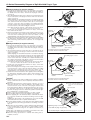
■Wiring Procedure (for positive common)
q Press down the upper part of the cover, and open it. Loosen the
mounting screws of the valves next to the valve base assemblies to
be added, remove the valves, and remove the plug-in connector
(see Fig. 4).
w The end terminal lead wire (short, red wire) is inserted into the pin
insert section (No.4) of the plug-in connectors that were removed in
step q (see Fig. 5).
(When shipping, the end terminal lead wire is inserted into the plugin connector of the end unit valve.) Remove this end terminal lead
wire, and insert it into the insertion section (No. 4) of the plug-in
connector of the valve base assembly to be added. Afterward,
insert the common wire (red) of this plug-in connector into the insertion section (No.4) of the removed plug-in connector.
Note: When inserting the lead wire, confirm that the short bar of the plug-in
connector’s common wire insertion section has been attached.
e Install each of the wired plug-in connectors in step w to the valve
base, and mount the valve.
r Remove the wiring block mounting screws and place them in the positions shown in Fig. 7, then connect the lead wire (white) of the added
valve base after confirming the pin location (For details, see the
detailed diagram of the wiring block internal connections on p.184).
t Return the connector brackets to their original position, and tighten
the wiring block mounting screws in place, then install the cover
while exercising caution that the lead wires are not trapped by
the cover.
Figure 4
Plug-in connector
Pull straight out
Figure 5 ● For positive common
Newly adding plug-in connector
End terminal
lead wire (Red)※1
Lead wire (White)※2
Lead wire (White)※2
Common wire (Red)
■Wiring Procedure (for negative common)
q Press down the upper part of the cover, and open it. Loosen the
mounting screws of the valves next to the valve base assemblies to
be added, remove the valves, and remove the plug-in connectors
(see Fig. 4).
w The end terminal lead wire (short, black wire) is inserted into the pin
insert section (No.3) of the plug-in connectors that were removed in
step q (see Fig. 6).
(When shipping, the end terminal lead wire is inserted into the plugin connector of the end unit valve.) Remove this end terminal lead
wire, and insert it into the insertion section (No.3) of the plug-in connector for the valve base assembly to be added. Afterward, insert
the common wire (black) of this plug-in connector into the insertion
section (No.3) of the removed plug-in connector.
Note: When inserting the lead wire, confirm that the short bar of the plug-in
connector’s common wire insertion section has been attached.
e Install each of the wired plug-in connectors in step w to the valve
base, and mount the valve.
r Remove the wiring block mounting screws and place them in the positions shown in Fig. 7, then connect the lead wire (white) of the added
valve base after confirming the pin location (For details, see the
detailed diagram of the wiring block internal connections on p.184).
t Return the connector brackets to their original position, and tighten
the wiring block mounting screws in place, then install the cover
while exercising caution that the lead wires are not trapped by
the cover.
【 Caution】
● Always cut off the power and air supply before working. In addition,
always confirm that air has been completely exhausted from the
manifold.
● When removing lead wires from the plug-in connector, use a tool
with a fine tip (such as a small screwdriver) to press lightly on the
contact hook from a hole on the side of the plug-in connector, and
pull out the lead wire. When re-inserting the lead wire to the connector, spread the contact hooks so that they face outward, and then
insert into the plug-in connector. At this time, pull the lead wire lightly to confirm that it is securely inserted.
● Always connect the end terminal lead wire. (see Figs. 5 and 6)
● Care should be taken not to become trapped or lose gaskets.
● Before supplying air to the manifold, always confirm that the bases
are connected, and that the end block mounting screws are tightened, etc.
Supplying air when either of the end blocks do not secure the DIN
rail could result in air leaks or separate manifold bases.
● Be aware that the number of valve units that can be added is limited
in the manifold, by the wiring specifications and wiring connection
type, etc.
● When there are large number of valves simultaneously delivering air
to the secondary side, or when there is a large number of valves
overall, we recommend using two air supplies and exhausts (on
each side).
Adding units of the piping block assembly is performed in the same
way as adding units of the valve base assembly.
● When the wiring specification is -D370U and adding units is
required, consult us.
183
Contact
Common wire (Red)
Replace the end terminal
lead wire.
End terminal lead wire
(Short, red wire)
※1: Always insert the end terminal lead wire.
※2: Shows when both A and B are used.
Figure 6 ● For negative common
Newly adding plug-in connector
End terminal
lead wire (Black)※1
Common wire (Black)
Lead wire (White)※2
Lead wire (White)※2
Common wire (Black)
Contact
Replace the end terminal
lead wire.
End terminal lead wire
(Short, black wire)
※1: Always insert the end terminal lead wire.
※2: Shows when both A and B are used.
Figure 7
Note: For the serial transmission type,
remove the serial transmission
block.
Connector bracket
Tightening torque of mounting
screw:49N・cm {5kgf・cm} [4.3in・lbf].
Mounting screw
See “Detailed Diagram of Wiring Block Internal Connections” on p.184.
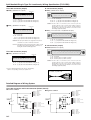
Detailed Diagram of Wiring Block Internal Connections
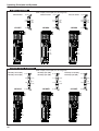
Flat cable connector 20, 26 pins
Note: As shown on the left, remove the connector
and then perform the wiring.
● For -F201□
Connection to power
supply terminals(+)
Pin locations with protruded
part upward.
15
13 6
1
11
9 2 14
7 0 1
1
5
8
3
6
1
4
2
Connection to power supply
terminals(−)
To plug-in
connector
Insert the contact so that the protruded
part latches.
Regarding the position
shown in the above
illustration, for the upper
part, insert the contact facing
upward, and for the lower part, insert the
contact facing downward.
● For -F260□
Pin locations with protruded
part upward.
Connection to power supply
terminals(+)
Pin locations with protruded
part upward.
1
2 1
3 1 1
4 1 2
1
3
15
4
16
5
17
18 7 6
8
C
9 N
Connection to power supply
7 1 NC
5 1 20
terminals(−)
1
8
3
1
1
6
Unused
pin
1
11
9 2 14
7
0 1
5
8 1
3
6
1
4
2
Connection to power
supply terminals
(−)
Connection to power supply
terminals(+)
To plug-in
connector
To plug-in
connector
D-sub connector
● For -D250□
Unused pins
● For -D370U
● For -D251□
5
7
9 6 4
1
3 1 8
5 1 12 10
1
NC 4
NC 16 1
NC
3
1
2
Unused pin
Insert the pin into
the additional locations
Connection to power supply
terminals(−)
2
3 14
4
5 16 15
6 17
7
8 19 18
9
0 21 2 0
1
NC 22
23
1
Unused pin
Insert the pin into
the additional locations
To plug-in connector
7
5
3
4
1
2
6
1
31 8
5 1 10
7 1 14 12
1
9
1 1 16
3 2 18
5 2 20
7 2 24 22
2
29
31 8 26
Insert the pin into
NC 30 2
32
the additional locations
COM(For negative common)
Connection to power supply
terminals(+)
Connection to power supply
terminals(−)
Connection to power supply
terminals(+)
9
COM(For positive common)
To plug-in connector
To plug-in connector
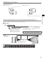
Serial transmission block
Pin locations with protruded
part upward.
8
9
0
0
1 1 1
1
2
2
3 1 3
1
4
14
15 6 5
NC
NC C 7
N
Unused pins
Note: As shown in the illustration above, remove the connector and then perform the wiring.
Note: Serial transmission blocks compatible with 8output cannot use pin Nos. 8∼15.
Insert the contact so that the protruded
part latches.
Regarding the position
shown in the left
illustration, for the upper
part, insert the contact facing
upward, and for the lower part, insert the
contact facing downward.
To plug-in connector
184
SOLENOID VALVES JA SERIES
● For -F200□
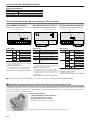
Serial Transmission Block Specifications
General Specifications
Voltage
DC24V ±10%
Operating temperature range
5∼50°C [41∼122°F]
Vibration resistance
49.0m/s2 {5.0G} (Conforms to JIS C 0911)
Shock resistance
98.1m/s2 {10.0G} (Conforms to JIS C 0912)
●For details of specifications, see the user’s manual. (See below)
Serial Transmission Block and Terminal Block (LED) Part Names
●For OMRON CompoBus/S
●For Mitsubishi Electric CC-Link
● For DeviceNet (OMRON CompoBus/D)
Transmission block specification: -A1 (16 outputs), -A2 (8 outputs)
Transmission block specification: -B1
Transmission block specification: -D1
Dip switch for various settings
L RUN L ERR.
O
N
PW
O
N
RD
1
2
3
4
5
6
7
8
9
0
PWR COMM ERR
MS
NS
1
2
3
4
5
6
O
N
O
N
SD
Dip switch for various settings
1
2
3
4
5
6
7
8
9
0
Dip switch for various settings
LED indicator
Indicator
PWR
COMM
ERR
State
Lights up
Shut off
Lights up
Shut off
Lights up
Shut off
LED indicator
color
Green
Yellow
Red
Description
Indicator
PW
•During power supply
•Power is not supplied
L RUN
•During normal communication
V+
Drain
V−
CAN H
0V (FG)
0V
24V
(FG)
SLD
DB
DG
24V
CAN L
BDL BS−
DA
BS+ BDH
LED indicator
Description
Indicator
State
•Lights up when power is turned on
Lights up
•Lights up when normal data is
•received from a master station
Flashing
MS
Lights up
color
Green
Description
•Normal status
•No setting status
Red
•Serious breakdown
•Communication fault, or standby
SD
•Lights up during sending data
Flashing
•Minor breakdown
•Communication fault occurred
RD
•Lights up during receiving data
Shut off
•No power supply
•Lights up during transmission errors, and shuts off when time is over.
Lights up during a station number setting error or transmission speed
setting error
Lights up
•During normal communication, or standby
L ERR.
Remarks
※ For details about CompoBus/S, see the OMRON
catalog, user’s manual, etc.
● Number of outputs per block
16 solenoids (transmission block specification: -A1)
8 solenoids (transmission block specification: -A2)
● Related materials: User’s manual, document No.HV030
Remarks
NS
※ For details about CC-Link, see the Mitsubishi
Electric catalog, user’s manual, etc.
● Number of outputs per block
16 solenoids (transmission block specification: -B1)
※ Since the block occupies one station, if the block
is entirely composed of remote I/O stations, a
maximum of 64 units can be connected to one
master station.
Green
Flashing
Lights up
•Communication connection achieved
•No communication connection
Red
•Serious communication fault
Flashing
•Minor communication fault
Shut off
•No power supply
Remarks
※ Conforms to DeviceNet (CompoBus/D)
● Number of outputs per block
Maximum of 16 solenoids
● Related materials: User’s manual, document No.HV032
● Related materials: User’s manual, document No.HV031
■For details about specifications and handling, see the above-listed user’s manuals (Document No. HV030∼HV032).
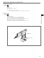
■Application Examples for Serial Transmission Block of General Purpose Type
If manifolds with flat cable connectors released previously have F201 wiring specifications (with positive common specifications only), the
serial transmission blocks (general purpose type with F201 compatible flat cable) YS5□U can be connected to the manifold to convert it
into a serial transmission-compatible manifold.
●Connectable Manifolds
・FM-SOLID MANIFOLD X80M, X88M Series
・Koganei Solenoid Valves F series
・Koganei Solenoid Valves JA series
※ Voltage should meet DC24V specifications.
(Flat cable length approximately 90mm [3.5in.], DIN rail length 75mm [3in.])
185
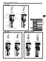
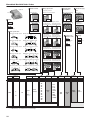
Operating Principles and Symbols
2-port
Normally closed (NC)
4(A)
Column
Normally open (NO)
1(P)
2(B)
1(P)
JA10A1
JA10A2
De-energized
De-energized
Plunger spring
Plunger
Piston
Manual override
Major Parts and Materials
Exhaust valves
Parts
Materials
Body
Aluminum alloy (anodized)
Stem
Aluminum alloy
Exhaust valve
Flapper
Lip seal
(
4 A)
Valve
(
1 P)
(
1 P)
(
2 B)
Valve body
Stem
End cover
Sub-base
Aluminum alloy (anodized)
Plunger
Column
Magnetic stainless
steel
End cover
Plastic
Monoblock Aluminum alloy (anodized)
Body
Lip seal
Manifold
Split type Plastic
Block-off plate Mild steel (nickel plated)
Seal
3-port
Synthetic rubber
5-port, 2-position
Normally closed (NC)
Normally open (NO)
Single solenoid
14(SA)
4(A)
Synthetic rubber
Flapper
1(P)
5(R1)
2(B)
1(P)
3(R2)
4(A)
2(B)
Double solenoid
14(SA)
5(R1)
1(P)
3(R2)
4(A)
2(B)
5(R1)
1(P)
3(R2)
12(SB)
JA10A3
JA10A4
JA10A5
De-energized
De-energized
De-energized
JA10A6
De-energized condition after
energizing solenoid 12(SB)
(
5 R1)
(
5 R1)
(
5 R1)
(
4 A)
(
4 A)
(
4 A)
(
1 P)
(
1 P)
(
1 P)
(
2 B)
(
2 B)
(
2 B)
(
3 R2)
(
3 R2)
(
3 R2)
(
1 P)
186
SOLENOID VALVES JA SERIES
Molded solenoid
Operating Principles and Symbols
5-port, 3-position
〔Both 14 (SA) and 12 (SB) are de-energized〕
Closed center
Exhaust center
14(SA)
4(A)
2(B)
JA10A7
5(R1)
1(P)
3(R2)
4(A)
2(B)
JA10A8
12(SB)
Pressure center
14(SA)
14(SA)
5(R1)
1(P)
3(R2)
4(A)
2(B)
JA10A9
12(SB)
5(R1)
1(P)
3(R2)
12(SB)
(
5 R1)
(
5 R1)
(
5 R1)
(
4 A)
(
4 A)
(
4 A)
(
1 P)
(
1 P)
(
1 P)
(
2 B)
(
2 B)
(
2 B)
(
3 R2)
(
3 R2)
(
3 R2)
Tandem 3-port, 4-position
〔Both 14 (SA) and 12 (SB) are de-energized〕
Normally closed (NC),
Normally closed (NC)
Normally open (NO), 14(SA)
Normally open (NO)
14(SA)
4(A)
5(R1)
4(A)
1(P)
2(B)
JA10AA
187
12(SB)
Normally closed (NC), 14(SA)
Normally open (NO)
5(R1)
4(A)
1(P)
2(B)
3(R2)
JA10AB
12(SB)
5(R1)
1(P)
2(B)
3(R2)
JA10AC
12(SB)
(
5 R1)
(
5 R1)
(
5 R1)
(
4 A)
(
4 A)
(
4 A)
(
1 P)
(
1 P)
(
1 P)
(
2 B)
(
2 B)
(
2 B)
(
3 R2)
(
3 R2)
(
3 R2)
3(R2)
Series Order Codes
SOLENOID VALVES JA SERIES
The Solenoid Valves JA series order codes are
classified into the following 5 categories.
For details of order codes, see the designated
pages.
JA10A□:Single valve unit
p. 189
JAM□AJ:Monoblock manifold
p. 191
JAM□NJ:Split manifold non-plug-in type
p. 193
JAM□PJ:Split manifold plug-in type
p. 197
JAM□SJ:Serial transmission type
p. 201
188
Single Valve Unit Order Codes
■Sub-base
■Wiring specification
Without sub-baseNote1
Blank
JA10
Standard type
JA10L
Low current type
-PN
Blank
With sub-baseNote2
■Model
S type plug connector
Without connector and leads
Plug-in
Positive common
Positive common
S type plug connector
S type plug connector
Lead wire 300mm [11.8in.] Lead wire 3000mm [118in.]
■Valve specification
A1:2-port normally closed
(A)
4
(B)
(A)
2 4
(SB)
12
1
(P)
-PS
(SA)
14
3 1 5
(R2)
(P)
(R1)
A2:2-port normally open
(B)
2
■ Manual override
A8:3-position, exhaust center
(B)
(A)
2 4
(SB)
12
1
(P)
Non-locking type
-PS3
Negative common
Negative common
S type plug connector
S type plug connector
Lead wire 300mm [11.8in.] Lead wire 3000mm [118in.]
(SA)
14
3 1 5
(R2)
(P)
(R1)
A3:3-port normally closed
(A)
4
A9:3-position, pressure center
(B)
(A)
2 4
(SB)
12
A4:3-port normally open
(B)
2
3 1
(P)
(R2)
(B)
(A)
2 4
(SA)
14
Valve specification
JA10
JA10L
A1
A2
A3
A4
A5
A6
A7
A8
A9
AA
AB
AC
(A)
4
(SA)
14
■Voltage
5
(R1)
-83
-D4
(A)
4
DC24V
-D5
(SA)
14
Note3
DC12V
5
(R1)
AC:Tandem 3-port
(normally closed & normally open)
(B)
2
(SB)
12
3 1 5
(R2)
(P)
(R1)
Model
(B)
2
(SB)
12
3
1
(R2) (P)
A6:5-port 2-position,
double solenoid
Locking protruding type
AB:Tandem 3-port
(normally open & normally open)
3 1 5
(R2)
(P)
(R1)
(B)
(A)
2 4
(B)
2
3
1
(R2) (P)
(SA)
14
-MS3
AA:Tandem 3-port (normally closed & normally closed)
(SB)
12
A5:5-port 2-position,
single solenoid
-MS
Blank
(SA)
14
3 1 5
(R2)
(P)
(R1)
5 1
(R1)
(P)
(SB)
12
-25
A7:3-position, closed center
3
1
(R2) (P)
Sub-base
(A)
4
(SA)
14
5
(R1)
Manual override
Wiring specification
Voltage
Blank Note2
Blank
-25 Note2
Blank
-83
-PN
-PS
-PS3
-MS
-MS3
-D4
-D5 Note3
Notes: 1. Cannot be used as a single valve unit. Two manifold mounting screws are provided.
2. When ordering with a sub-base, the “Blank (plug-in)” cannot be selected as the wiring specification. Select from among -PN, -PS, -PS3, -MS or -MS3.
3. -D5(DC12V) is not available in the low current type.
189
Additional Parts Order Codes for Single Valve Unit
Parts for single valve unit
JAZ Parts content
25 : Sub-base (sub-base and gasket) Note 1
GS1 : GasketNote 2
Notes: 1. Valve mounting screws are not included.
2. Care should be taken that this gasket is different from the GS2 gasket for the split manifolds.
Connector-related
SOLENOID VALVES JA SERIES
JAZ Connector specification
CP : Positive common plug connector, lead wire length 300mm [11.8in.]
CP3 : Positive common plug connector, lead wire length 3000mm [118in.]
CPN : Positive common plug connector, without lead wire (short bar and contacts included)
CM : Negative common plug connector, lead wire length 300mm [11.8in.]
CM3 : Negative common plug connector, lead wire length 3000mm [118in.]
CMN : Negative common plug connector, without lead wire (short bar and contacts included)
JAZ-GS1:Gasket
JAZ-25:Sub-base
190
Monoblock Manifold Order Codes
■Manual override
■Manifold fitting
specification
■Wiring specification
Right side
S type plug connector
Without connector and leads
Non-locking type
Left side
JA10
With φ4[0.157in.] fittings
-PN
Blank
■Model
Without spacer
-J4K
Positive common
Negative common
S type plug connector
S type plug connector
Lead wire 300mm [11.8in.] Lead wire 300mm [11.8in.]
Locking protruding type
Standard type
■ Individual air supply
spacer
Blank
With φ6[0.236in.] fittings
With individual
air supply spacer
JA10L
Low current type
-83
-J6K
■Valve specification
-PS
A1:2-port normally closed
(A)
4
A7:3-position, closed center
(B)
(A)
2 4
(SB)
12
1
(P)
-NPM
-MS
Positive common
Negative common
S type plug connector S type plug connector
Lead wire 3000mm [118in.] Lead wire 3000mm [11.8in.]
(SA)
14
3 1 5
(R2)
(P)
(R1)
A2:2-port normally open
(B)
(A)
2 4
(SB)
12
1
(P)
(A)
4
-PS3
(B)
(A)
2 4
(SA)
14
DC24V
-D5
Note2
DC12V
-E1
-MS3
Positive common pre-wired terminal Negative common pre-wired terminal
S type plug connector
S type plug connector
Lead wire 300mm [11.8in.] Lead wire 300mm [11.8in.]
A9:3-position, pressure center
(SB)
12
-D4
Without back pressure
prevention valve
(SA)
14
3 1 5
(R2)
(P)
(R1)
A3:3-port normally closed
■Voltage
Blank
A8:3-position, exhaust center
(B)
2
■Back pressure
prevention valve
With back pressure
prevention valve
3 1 5
(R2)
(P)
(R1)
5 1
(R1)
(P)
A4:3-port normally open
AA:Tandem 3-port (normally closed & normally closed)
(B)
2
(SB)
12
3 1
(P)
(R2)
(B)
2
3
1
(R2) (P)
(A)
4
(SA)
14
-CPS
5
(R1)
Positive common pre-wired terminal Negative common pre-wired terminal
S type plug connector S type plug connector
Lead wire 3000mm [118in.] Lead wire 3000mm [118in.]
A5:5-port 2-position, single sol. AB:Tandem 3-port (normally open & normally open)
(B)
(A)
2 4
(SB)
12
(SA)
14
3 1 5
(R2)
(P)
(R1)
(B)
2
3
1
(R2) (P)
(A)
4
-CMS
(SA)
14
5
(R1)
A6:5-port 2-position, double sol. AC:Tandem 3-port (normally closed & normally open)
(SB)
12
(B)
(A)
2 4
(SB)
12
(SA)
14
3 1 5
(R2)
(P)
(R1)
Model
(B)
2
3
1
(R2) (P)
Number of
units
Station
(A)
4
(SA)
14
-CPS3
Model
Valve
specification
Manual
override
Manifold model
JAM
2
・
・
・
20
-CMS3
5
(R1)
Wiring
specification
Manifold
Back pressure
Individual air
fitting specification prevention valve supply spacer
Mounting valve model
AJ
stn. 1
・
・
・
stn.□
Note1
JA10
JA10L
A1
A2
A3
A4
A5
A6
A7
A8
A9
AA
AB
AC
Blank
-83
-PN
-PS
-PS3
-CPS
-CPS3
-MS
-MS3
-CMS
-CMS3
JABP (for block-off plate)
Notes: 1. Valve mounting location is from the left, with the solenoid on top, and the 4(A) and 2(B) ports in front.
2. -D5 (DC12V) is not available in the low current type.
191
Voltage
Blank
-J4K
-J6K
Blank
-E1
-NPM
-D4
-D5Note2
Additional Parts Order Codes for Monoblock Manifold
Manifold parts
JAZ Parts description
GS1 : Gasket
E1 : Back pressure prevention valve (2 pcs. for monoblock type)
J4K :φ4 fitting (2 pcs. for monoblock type, and 1 pc. gasket)
J6K :φ6 fitting (2 pcs. for monoblock type, and 1 pc. gasket)
NPM: Individual air supply spacer
(Spacer body, gasket and 2 mounting screws)
JAZ-GS1:Gasket
JABP:Block-off plate
SOLENOID VALVES JA SERIES
Block-off plate (block-off plate and 2 mounting screws)
JABP
Connector-related
JAZ Connector specification
CP : Positive common plug connector, lead wire length 300mm [11.8in.]
CP3 : Positive common plug connector, lead wire length 3000mm [118in.]
CPN : Positive common plug connector, without lead wire (short bar and contacts included)
PA : Positive common A type, plug connector lead wire length 300mm※ [11.8in.]
PA3 : Positive common A type, plug connector lead wire length 3000mm※ [118in.]
PB : Positive common B type, plug connector lead wire length 300mm※ [11.8in.]
PB3 : Positive common B type, plug connector lead wire length 3000mm※ [118in.]
PC : Positive common C type, plug connector lead wire length 300mm※ [11.8in.]
PC3 : Positive common C type, plug connector lead wire length 3000mm※ [118in.]
CM : Negative common plug connector, lead wire length 300mm [11.8in.]
CM3 : Negative common plug connector, lead wire length 3000mm [118in.]
CMN : Negative common plug connector, without lead wire (short bar and contacts included)
MA : Negative common A type, plug connector lead wire length 300mm※ [11.8in.]
MA3 : Negative common A type, plug connector lead wire length 3000mm※ [118in.]
MB : Negative common B type, plug connector lead wire length 300mm※ [11.8in.]
MB3 : Negative common B type, plug connector lead wire length 3000mm※ [118in.]
MC : Negative common C type, plug connector lead wire length 300mm※ [11.8in.]
MC3 : Negative common C type, plug connector lead wire length 3000mm※ [118in.]
※For details, see p.178.
Manifold Order Code Example (6 units of JA
series)
JAM6AJ
stn.1∼2 JA10A5-PS-J4K-D4
stn.3∼5 JA10A6-PS-J6K-D4
stn.6
JABP-J6K
Note: This order code example has no relation to the illustration above.
Precautions for Order Codes
● Order for valves only
Place orders by “Single Valve Unit Order Codes” on p.189.
For common terminal wiring connections, order separately the common connector assemblies listed above.
192
Split Manifold Non-Plug-in Type Order Codes
■Piping block specification (air supply and exhaust)
Right side
Left side
-JR
-JL
-JD
-JR1/4
-JL1/4
-JD1/4
-JR3/8
-JL3/8
-JD3/8
:1(P) and 3, 5(R) ports φ8 [0.315in.] fitting right-side mounting
:1(P) and 3, 5(R) ports φ8 [0.315in.] fitting left-side mounting
:1(P) and 3, 5(R) ports φ8 [0.315in.] fitting both-side mounting
:1(P) and 3, 5(R) ports 1/4 inch fitting right-side mounting
:1(P) and 3, 5(R) ports 1/4 inch fitting left-side mounting
:1(P) and 3, 5(R) ports 1/4 inch fitting both-side mounting
:1(P) and 3, 5(R) ports 3/8 inch fitting right-side mounting
:1(P) and 3, 5(R) ports 3/8 inch fitting left-side mounting
:1(P) and 3, 5(R) ports 3/8 inch fitting both-side mounting
■Model
JA10
Standard type
JA10L
Low current type
■Valve specification
A1: 2-port normally closed
(A)
4
The photo shows the -JR type.
-MR
-ML
-MD
-MR1/4
-ML1/4
-MD1/4
-MR3/8
-ML3/8
-MD3/8
A7: 3-position, closed center
(SB)
12
1
(P)
:1(P) port φ8 [0.315in.] fitting, 3, 5(R) ports built-in
muffler right-side mounting
:1(P) port φ8 [0.315in.] fitting, 3, 5(R) ports built-in
muffler left-side mounting
:1(P) port φ8 [0.315in.] fitting, 3, 5(R) ports built-in
muffler both-side mounting
:1(P) port 1/4 inch fitting, 3, 5(R) ports built-in muffler
right-side mounting
:1(P) port 1/4 inch fitting, 3, 5(R) ports built-in muffler
left-side mounting
:1(P) port 1/4 inch fitting, 3, 5(R) ports built-in muffler
both-side mounting
:1(P) port 3/8 inch fitting, 3, 5(R) ports built-in muffler
right-side mounting
:1(P) port 3/8 inch fitting, 3, 5(R) ports built-in muffler
left-side mounting
:1(P) port 3/8 inch fitting, 3, 5(R) ports built-in muffler
both-side mounting
(B)
(A)
2 4
(SA)
14
3 1 5
(R2)
(P)
(R1)
A2: 2-port normally open
(B)
2
A8: 3-position, exhaust center
(SB)
12
1
(P)
(B)
(A)
2 4
(SA)
14
3 1 5
(R2)
(P)
(R1)
A3: 3-port normally closed
(A)
4
A9: 3-position, pressure center
(SB)
12
(B)
(A)
2 4
(SA)
14
3 1 5
(R2)
(P)
(R1)
5 1
(R1)
(P)
A4: 3-port normally open
(B)
2
AA: Tandem 3-port (normally closed & normally closed)
(SB)
12
3 1
(P)
(R2)
(B)
2
3
1
(R2) (P)
(A)
4
(SA)
14
5
(R1)
A5: 5-port 2-position, single sol. AB: Tandem 3-port (normally open & normally open)
(B)
(A)
2 4
(SA)
14
(SB)
12
3 1 5
(R2)
(P)
(R1)
(B)
2
3
1
(R2) (P)
(A)
4
(SA)
14
5
(R1)
A6: 5-port 2-position, double sol. AC: Tandem 3-port (normally closed & normally open)
The photo shows the -MR type.
(SB)
12
(B)
(A)
2 4
(SA)
14
(SB)
12
3 1 5
(R2)
(P)
(R1)
Model
(B)
2
3
1
(R2) (P)
193
2
・
・
・
20
5
(R1)
Piping block specification
(air supply and exhaust)
Valve units
Manifold model
JAM
(A)
4
NJ
-JR
-JL
-JD
-JR1/4
-JL1/4
-JD1/4
-JR3/8
-JL3/8
-JD3/8
-MR
-ML
-MD
-MR1/4
-ML1/4
-MD1/4
-MR3/8
-ML3/8
-MD3/8
(SA)
14
■Wiring specification
S type plug connector
Without connector ass’y
Non-locking type
Negative common
Positive common
S type plug connector
S type plug connector
Lead wire 300mm [11.8in.] Lead wire 300mm [11.8in.]
-PN
Blank
Locking protruding type
-MS
-PS
■Manifold fitting
specification
■ Individual air supply spacer
With φ4[0.157in.] fittings
Without spacer
-J4
Negative common
Positive common
S type plug connector S type plug connector
Lead wire 3000mm [118in.] Lead wire 3000mm [118in.]
-83
Blank
With φ6[0.236in.] fittings
With individual air supply spacer
-J6
-MS3
-PS3
Positive common
pre-wired terminal
S type plug connector
Lead wire 300mm [11.8in.]
-NPM
With 1/8 inch fittings
Negative common
pre-wired terminal
S type plug connector
Lead wire 300mm [11.8in.]
■Port isolator
Blank : Without port isolator
-S1 : For 1(P) port
-S3 : For 3(R2) and 5(R1) ports
-SA : For 1(P), 3(R2) and 5(R1) ports
-J1/8
With 1/4 inch fittings
-CMS
-CPS
Positive common
pre-wired terminal
S type plug connector
Lead wire 3000mm [118in.]
■Voltage
Negative common
pre-wired terminal
S type plug connector
Lead wire 3000mm [118in.]
-D4
-J1/4
DC24V
-D5
Note3
DC12V
■Back pressure
prevention valve
Blank
-CMS3
-CPS3
Without back pressure
prevention valve
-E2
With back pressure
prevention valve
Station
Model
Valve
specification
Manual override
Wiring
specification
Back pressure
Manifold
fitting specification prevention valve
Individual air
supply spacer
Port isolator
Voltage
Blank
Blank
-D4
-D5Note3
Mounting valve model
stn. 1
・
・
・
stn.□
Note1
JA10
JA10L
A1
A2
A3
A4
A5
A6
A7
A8
A9
AA
AB
AC
Blank
-83
-PN
-PS
-PS3
-CPS
-CPS3
-MS
-MS3
-CMS
-CMS3
-J4
-J6
-J1/8
-J1/4
Blank
-E2
-NPM
Note2
-S1
-S3Note2
-SANote2
JABP (for block-off plate)
Notes: 1. Valve mounting location is from the left, with the solenoid on top, and the 4(A) and 2(B) ports in front.
2. Port isolators can be installed only when piping blocks are mounted on both sides. In addition, only one location for each port isolator can be installed in
one manifold for -SA, or one each port isolator for -S1 and -S3 for a total of two locations. When shipping, the designated port isolators are installed
between the designated station and the station to its immediate left (the next smaller stn. No.).
3. -D5 (DC12V) is not available in the low current type.
194
SOLENOID VALVES JA SERIES
■Manual override
Additional Parts Order Codes for Split Manifold Non-Plug-in Type
Manifold parts
Block-off plate (block-off plate and 2 mounting screws)
JABP
JAZ -
Parts description
GS2 : Gasket (for split type)
E2
: Back pressure prevention valve (2 pcs. for split type and 1 pc. gasket)
Piping block assembly
J4
: 2 pcs. φ4 fittings, and 1 pc. stopper pin
JAZ J6
: 2 pcs. φ6 fittings, and 1 pc. stopper pin
J8
: 2 pcs. φ8 fittings, and 1 pc. stopper pin
J1/8 : 2 pcs. 1/8 inch fittings, and 1 pc. stopper pin
Piping specification
J1/4 : 2 pcs. 1/4 inch fittings, and 1 pc. stopper pin
PJ
:1(P) and 3, 5(R) ports φ8 fittings
J1/4P : 2 pcs. 1/4 inch fittings for 1(P) and 3, 5(R) ports, and 1 pc. stopper pin
PJ1/4 :1(P) and 3, 5(R) ports 1/4 inch fittings
J3/8 : 2 pcs. 3/8 inch fittings, and 1 pc. stopper pin
PJ3/8 :1(P) and 3, 5(R) ports 3/8 inch fittings
M
: Muffler for piping block
PM :1(P) port φ8 fitting, 3, 5(R) ports built-in mufflers
NPM : Individual air supply spacer (spacer body, gasket and 2 mounting screws)
PM1/4:1(P) port 1/4 inch fitting, 3, 5(R) ports built-in mufflers
S1
: Port isolator for 1(P) port
PM3/8:1(P) port 3/8 inch fitting, 3, 5(R) ports built-in mufflers
S3
: Port isolator for 3(R2) and 5(R1) ports
SA : Port isolator for 1(P) port, 3(R2) and 5(R1) ports
End blocks (one set of left and right)
JAZ - E
Connector-related
JAZ -
Valve base assembly (valve base and gasket)
JAZ -
Connector specification
CP : Positive common plug connector, lead wire length 300mm [11.8in.]
CP3 : Positive common plug connector, lead wire length 3000mm [118in.]
CPN : Positive common plug connector, without lead wire (short bar and contacts included)
PA : Positive common A type, plug connector lead wire length 300mm※ [11.8in.]
PA3 : Positive common A type, plug connector lead wire length 3000mm※ [118in.]
PB : Positive common B type, plug connector lead wire length 300mm※ [11.8in.]
PB3 : Positive common B type, plug connector lead wire length 3000mm※ [118in.]
PC : Positive common C type, plug connector lead wire length 300mm※ [11.8in.]
PC3 : Positive common C type, plug connector lead wire length 3000mm※ [118in.]
CM : Negative common plug connector, lead wire length 300mm [11.8in.]
CM3 : Negative common plug connector, lead wire length 3000mm [118in.]
CMN : Negative common plug connector, without lead wire (short bar and contacts included)
MA : Negative common A type, plug connector lead wire length 300mm※ [11.8in.]
MA3 : Negative common A type, plug connector lead wire length 3000mm※ [118in.]
MB : Negative common B type, plug connector lead wire length 300mm※ [11.8in.]
MB3 : Negative common B type, plug connector lead wire length 3000mm※ [118in.]
MC : Negative common C type, plug connector lead wire length 300mm※ [11.8in.]
MC3 : Negative common C type, plug connector lead wire length 3000mm※ [118in.]
※For details, see p.178.
195
Piping specification
VJ4 :With φ4 fitting
VJ6 :With φ6 fitting
VJ1/8 :With 1/8 inch fitting
VJ1/4 :With 1/4 inch fitting
JAZ-GS2:Gasket
JABP:Block-off plate
SOLENOID VALVES JA SERIES
JAZ-S1:Port isolator for 1(P) port
End block
Piping block assembly
Valve base assembly
JAZ-S3:Port isolators for 3(R2) and 5(R1) ports
Manifold Order Code Example (6 units of JA
series)
JAM6NJ-JR
stn.1∼2 JA10A5-PS-J4-D4
stn.3∼5 JA10A6-PS-J6-D4
stn.6
JABP-J6
Note: This order code example has no relation to the illustration above.
Precautions for Order Codes
● Order for valves only
Place orders by “Single Valve Unit Order Codes” on p.189.
For wiring specifications, Blank (plug-in type valve) cannot be selected.
For common terminal wiring connections, order separately the common connector assemblies listed to the left.
196
Split Manifold Plug-in Type Order Codes
■Wiring specification
(wiring block)
Right side
Left side
■Wiring connection specification
Blank
Flat cable connector
(with socket and strain relief)
D-sub connector
Packed wiring : Wiring is made in accordance
with the mounted valve
specifications.Note
-D
-D25□E□
-F□
■Piping block specification
(air supply and exhaust)
-D250E : 25-pin (connector on side)
(M2.6 mounting screws)
-D251E : 25-pin (connector on side)
(M2.6 mounting screws)
-D250EU: 25-pin (connector on side)
(4-40UNC mounting screws)
-D251EU: 25-pin (connector on side)
(4-40UNC mounting screws)
-F200 : 20-pin (connector on upper side)
-F201 : 20-pin (connector on upper side)
-F260 : 26-pin (connector on upper side)
-JR :1(P) and 3, 5(R) ports φ8 [0.315in.] fitting right-side mounting
-JL :1(P) and 3, 5(R) ports φ8 [0.315in.] fitting left-side mounting
-JD :1(P) and 3, 5(R) ports φ8 [0.315in.] fitting both-side mounting
-JR1/4 :1(P) and 3, 5(R) ports 1/4 inch fitting right-side mounting
-JL1/4 :1(P) and 3, 5(R) ports 1/4 inch fitting left-side mounting
-JD1/4 :1(P) and 3, 5(R) ports 1/4 inch fitting both-side mounting
-JR3/8 :1(P) and 3, 5(R) ports 3/8 inch fitting right-side mounting
-JL3/8 :1(P) and 3, 5(R) ports 3/8 inch fitting left-side mounting
-JD3/8 :1(P) and 3, 5(R) ports 3/8 inch fitting both-side mounting
Double wiring : Wiring is always the one for
the double solenoid, regardless of the specifications of
the mounted valve.Note
-F□E
Note: The wiring for the block-off
plate is normally the one for the
double solenoid. However,
when -S is designated as the
block-off plate wiring specification, the block-off plate wiring
of the station is changed to the
single solenoid.
■Pre-wired common
-F200E : 20-pin (connector on side)
-F201E : 20-pin (connector on side)
-F260E : 26-pin (connector on side)
Blank
Positive common
D-sub connector
-CM
-D370U
Negative common
-D370U: 37-pin (connector on upper side)
(4-40UNC mounting screws)
The photo shows the -JR type.
-MR :1(P) port φ8 [0.315in.] fitting, 3, 5(R) ports built-in muffler right-side mounting
-ML :1(P) port φ8 [0.315in.] fitting, 3, 5(R) ports built-in muffler left-side mounting
-MD :1(P) port φ8 [0.315in.] fitting, 3, 5(R) ports built-in muffler both-side mounting
-MR1/4 :1(P) port 1/4 inch fitting, 3, 5(R) ports built-in muffler right-side mounting
-ML1/4 :1(P) port 1/4 inch fitting, 3, 5(R) ports built-in muffler left-side mounting
-MD1/4 :1(P) port 1/4 inch fitting, 3, 5(R) ports built-in muffler both-side mounting
-MR3/8 :1(P) port 3/8 inch fitting, 3, 5(R) ports built-in muffler right-side mounting
-ML3/8 :1(P) port 3/8 inch fitting, 3, 5(R) ports built-in muffler left-side mounting
-MD3/8 :1(P) port 3/8 inch fitting, 3, 5(R) ports built-in muffler both-side mounting
■Voltage
-D25□
-D4
-D250 : 25-pin (connector on upper side)
(M2.6 mounting screws)
-D251 : 25-pin (connector on upper side)
(M2.6 mounting screws)
-D250U : 25-pin (connector on upper side)
(4-40UNC mounting screws)
-D251U : 25-pin (connector on upper side)
(4-40UNC mounting screws)
DC24V
-D5
Note4
DC12V
※ For details of wiring specification, see p.205.
The photo shows the -MR type.
Model
Piping block specification
(air supply and exhaust)
Valve units
Wiring specification
Wiring connection
specification
pre-wired common
Voltage
Blank
Blank
-D
-CM
-D4
-D5Note4
Manifold model
JAM
2
・
・
・
□
Note1
PJ
-JR
-MR
-JL
-ML
-JD
-MD
-JR1/4 -MR1/4
-JL1/4 -ML1/4
-JD1/4 -MD1/4
-JR3/8 -MR3/8
-JL3/8 -ML3/8
-JD3/8 -MD3/8
-F200
-F201
-F260
-F200E
-F201E
-F260E
-D250
-D251
-D250U
-D251U
-D250E
-D251E
-D250EU
-D251EU
-D370U
Notes: 1. For the maximum number of units, see the table for the maximum number of valve units by wiring specification, on p.199.
197
■ Model
■ Manual override
Non-locking type
JA10
■ Manifold fitting specification ■ Back pressure prevention valve
With φ4[0.157in.] fittings
Locking protruding type
■ Block-off plate wiring
specification
Blank
Blank
Wiring is always the one for
the double solenoid.
Without back pressure prevention valve
Standard type
-E2
JA10L
Blank
-J4
-83
-S
With back pressure prevention valve
When -S is designated, the blockoff plate wiring of the station is
changed to the single solenoid.
With φ6[0.236in.] fittings
■Valve specification
■Individual air supply spacer
Without spacer
A1 : 2-port normally closed A7 : 3-position, closed center
(A)
4
(SB)
12
1
(P)
(B)
(A)
2 4
(SA)
14
-J6
3 1 5
(R2)
(P)
(R1)
A2 : 2-port normally open
(B)
2
1
(P)
With 1/8 inch fittings
(B)
(A)
2 4
-D5
Blank
With individual air supply spacer
-J1/8
A3 : 3-port normally closed A9 : 3-position, pressure center
(SB)
12
(B)
(A)
2 4
(SA)
14
With 1/4 inch fittings
3 1 5
(R2)
(P)
(R1)
5 1
(R1)
(P)
A4 : 3-port normally open
(B)
2
Note4
DC12V
(SA)
14
3 1 5
(R2)
(P)
(R1)
(A)
4
-D4
DC24V
A8 : 3-position, exhaust center
(SB)
12
■ Voltage
SOLENOID VALVES JA SERIES
Low current type
-PPM
AA : Tandem 3-port (normally closed & normally closed)
(SB)
12
(B)
2
(A)
4
(SA)
14
-J1/4
3 1
(P)
(R2)
3
1
(R2) (P)
5
(R1)
■ Port isolator
A5 : 5-port 2-position, single sol. AB : Tandem 3-port (normally open & normally open)
(B)
(A)
2 4
(SA)
14
(SB)
12
3 1 5
(R2)
(P)
(R1)
(B)
2
(A)
4
3
1
(R2) (P)
Blank : Without port isolator
-S1 : For 1(P) port
-S3 : For 3(R2) and 5(R1) ports
-SA : For 1(P),
3(R2) and 5(R1) ports
(SA)
14
5
(R1)
A6 : 5-port 2-position, double sol. AC : Tandem 3-port (normally closed & normally open)
(SB)
12
(B)
(A)
2 4
(SA)
14
(SB)
12
3 1 5
(R2)
(P)
(R1)
Station
(B)
2
(A)
4
3
1
(R2) (P)
Valve
specification
Model
(SA)
14
5
(R1)
Manual override
Manifold
fitting specification
Back pressure
prevention valve
Individual air
supply spacer
Port isolator
Block-off plate
wiring specification
Voltage
Mounting valve model
stn. 1
・
・
・
stn.□
Note2
JA10
JA10L
A1
A2
A3
A4
A5
A6
A7
A8
A9
AA
AB
AC
Blank
JABPP (for block-off plate)
-83
-D4
-D5Note4
Blank
-J4
-J6
-J1/8
-J1/4
-PPM
Blank
-E2
Blank
-S1Note3
-S3Note3
-SANote3
Blank
-S
Notes: 2. Valve mounting location is from the left, with the solenoid on top, and the 4(A) and 2(B) ports in front.
3. Port isolators can be installed only when piping blocks are mounted on both sides. In addition, only one location of each port isolator can be installed in
one manifold for -SA, or one each port isolator for -S1 and -S3, for a total of two locations. When shipping, the designated port isolators are installed
between the designated station and the station to its immediate left (the next smaller stn. No.).
4. -D5 (DC12V) is not available in the low current type.
198
Additional Parts Order Codes for Split Manifold Plug-in Type
Manifold parts
JAZ Parts description
GS2 : Gasket (for split type)
E2
: Back pressure prevention valve (2 pcs. for split type, and 1 pc. gasket)
J4
: 2 pcs.φ4 fittings, and 1 pc. stopper pin
J6
: 2 pcs.φ6 fittings, and 1 pc. stopper pin
J8
: 2 pcs.φ8 fittings, and 1 pc. stopper pin
J1/8 : 2 pcs. 1/8 inch fittings, and 1 pc. stopper pin
J1/4 : 2 pcs. 1/4 inch fittings, and 1 pc. stopper pin
J1/4P : 2 pcs. 1/4 inch fittings for 1(P) and 3, 5(R) ports, and 1 pc. stopper pin
J3/8 : 2 pcs. 3/8 inch fittings, and 1 pc. stopper pin
M
: Muffler for piping block
PPM : Individual air supply spacer (spacer body, gasket, 2 mounting screws, and connector Ass’y)
S1
: Port isolator for 1(P) port
S3
: Port isolator for 3(R2) and 5(R1) ports
SA : Port isolator for 1(P) port, 3(R2) and 5(R1) ports
Block-off plate (block-off plate, 2 mounting screws, and plug)
Piping block assembly
JABPP
JAZ Piping specification
PJ
:1(P) and 3, 5(R) ports φ8 fittings
PJ1/4 :1(P) and 3, 5(R) ports 1/4 inch fittings
PJ3/8 :1(P) and 3, 5(R) ports 3/8 inch fittings
PM :1(P) port φ8 fitting, 3, 5(R) ports built-in mufflers
PM1/4:1(P) port 1/4 inch fitting, 3, 5(R) ports built-in mufflers
PM3/8:1(P) port 3/8 inch fitting, 3, 5(R) ports built-in mufflers
Wiring block assembly (one set)
JAZ -
-
End blocks (one set of left and right)
-
JAZ - EP
Voltage
D4:DC24V
D5:DC12V
Pre-wired common
Blank : Positive common
CM : Negative common
Wiring specification
F200 : Flat cable connector
F201 : Flat cable connector
F260 : Flat cable connector
D250 : D-sub connector with M2.6 mounting screws
D251 : D-sub connector with M2.6 mounting screws
D250U: D-sub connector with 4-40 UNC mounting screws
D251U: D-sub connector with 4-40 UNC mounting screws
D370U: D-sub connector with 4-40 UNC mounting screws
Valve base assembly (valve base, gasket, lead wire and plug-in connector)
JAZ -
-
Pre-wired common
Blank: Positive common
CM : Negative common
Wiring specification
D : For D-sub connector
F : For flat cable connector
Piping specification
VJ4 : With φ4 fitting
VJ6 : With φ6 fitting
VJ1/8 : With 1/8 inch fitting
VJ1/4 : With 1/4 inch fitting
199
■Table for maximum number of valve units by wiring specification
Maximum number of units
Wiring specification
Wiring specification
Max. outputs
Packed wiring (Blank)
Double wiring (-D)
F200□ Flat cable (20P)
16
8 units
F201□ Flat cable (20P)
16
F260□ Flat cable (26P)
20
D250□ D-sub connector (25P)
16
D251□ D-sub connector (25P)
20
D370U D-sub connector (37P)
32
Varies depending on the mounted
number of single solenoids, double
solenoids and block-off plates.
The number of controllable solenoids
should be the maximum number of
outputs or less.
Max. 20 units possible.
8 units
10 units
8 units
10 units
16 units
JAZ-GS2:Gasket
JABPP:Block-off plate
SOLENOID VALVES JA SERIES
Plug
JAZ-S3:Port isolators for 3(R2) and 5(R1) ports
JAZ-S1:Port isolator for 1(P) port
Piping block assembly
Plug-in connector
Valve base assembly
End block
Wiring block assembly
Manifold Order Code Example (8 units of JA
series)
JAM8PJ-JR-F201-D4
stn.1∼4 JA10A5-J4-D4
stn.5∼7 JA10A6-J6-D4
stn.8
JABPP-J6
Note: This order code example has no relation to the illustration above.
Precautions for Order Codes
● Order for valves only
Place orders by “Single Valve Unit Order Codes” on p.189.
The wiring specification, however, is compatible with the Blank (plug-in type) only.
● Wiring connection specification
Blank (packed wiring) : Wiring is made in accordance with the mounted valve specifications.
-D (double wiring)
: Wiring is always for the double solenoid, regardless of the mounted valve specifications.
Note: The wiring for the block-off plate is normally the one for the double solenoid. However, when -S is designated as the block-off plate wiring specification, the block-off plate
wiring of the station is changed to the single solenoid.
200
Serial Transmission Type Order Codes
Right side
■Piping block specification
(air supply and exhaust)
Left side
■ Serial transmission block specification
※ These are serial transmission block
specifications compatible with each
system.
:1(P) and 3, 5(R) ports φ8 [0.315in.]
fitting right-side mounting
-JL
:1(P) and 3, 5(R) ports φ8 [0.315in.]
fitting left-side mounting
-JD
:1(P) and 3, 5(R) ports φ8 [0.315in.]
fitting both-side mounting
-JR1/4 :1(P) and 3, 5(R) ports 1/4 inch fitting
right-side mounting
-JL1/4 :1(P) and 3, 5(R) ports 1/4 inch fitting
left-side mounting
-JD1/4 :1(P) and 3, 5(R) ports 1/4 inch fitting
both-side mounting
-JR3/8 :1(P) and 3, 5(R) ports 3/8 inch fitting
right-side mounting
-JL3/8 :1(P) and 3, 5(R) ports 3/8 inch fitting
left-side mounting
-JD3/8 :1(P) and 3, 5(R) ports 3/8 inch fitting
both-side mounting
-JR
For details, see p.185.
■ Wiring connection specification
Blank
Packed wiring : Wiring is made in
accordance with the
mounted valve
specifications.Note
-D
-A1 : For Omron CompoBus/S (16 outputs)
-A2 : For Omron CompoBus/S (8 outputs)
-B1 : For Mitsubishi Electric CC-Link
-D1 : For DeviceNet (CompoBus/D)
Double wiring : Wiring is always the one
for the double solenoid,
regardless of the specifications of the mounted
valve.Note
Note: The wiring for the block-off
plate is normally the one for the
double solenoid. However,
when -S is designated as the
block-off plate wiring specification, the block-off plate wiring
of the station is changed to the
single solenoid.
The photo shows the -JR type.
:1(P) port φ8 [0.315in.] fitting, 3, 5(R)
ports built-in muffler right-side mounting
-ML
:1(P) port φ8 [0.315in.] fitting, 3, 5(R)
ports built-in muffler left-side mounting
-MD :1(P) port φ8 [0.315in.] fitting, 3, 5(R)
ports built-in muffler both-side mounting
-MR1/4 :1(P) port 1/4 inch fitting, 3, 5(R) ports
built-in muffler right-side mounting
-ML1/4 :1(P) port 1/4 inch fitting, 3, 5(R) ports
built-in muffler left-side mounting
-MD1/4 :1(P) port 1/4 inch fitting, 3, 5(R) ports
built-in muffler both-side mounting
-MR3/8 :1(P) port 3/8 inch fitting, 3, 5(R) ports
built-in muffler right-side mounting
-ML3/8 :1(P) port 3/8 inch fitting, 3, 5(R) ports
built-in muffler left-side mounting
-MD3/8 :1(P) port 3/8 inch fitting, 3, 5(R) ports
built-in muffler both-side mounting
-MR
The photo shows the -MR type.
Model
Piping block specification
(air supply and exhaust)
Valve units
Serial transmission block
specification
Wiring connection
specification
Manifold model
JAM
2
・
・
・
□
Note1
SJ
-JR
-JL
-JD
-JR1/4
-JL1/4
-JD1/4
-JR3/8
-JL3/8
-JD3/8
-MR
-ML
-MD
-MR1/4
-ML1/4
-MD1/4
-MR3/8
-ML3/8
-MD3/8
-A1
-A2
-B1
-D1
Blank
-D
Notes: 1. For the maximum number of units, see the table for the maximum number of valve units by serial transmission block specification, on p.203.
201
■ Manual override
■Model
Non-locking type
JA10
■ Manifold fitting specification■ Back pressure prevention valve
Locking protruding type
With φ4[0.157in.] fittings
Standard type
■Block-off plate wiring
specification
Blank
Blank
Without back pressure prevention valve
JA10L
Wiring is always the one for
the double solenoid.
-E2
Low current type
Blank
-83
With back pressure prevention valve
-J4
-S
When -S is designated, the blockoff plate wiring of the station is
changed to the single solenoid.
With φ6[0.236in.] fittings
■Valve specification
■ Individual air supply spacer
Without spacer
A1 : 2-port normally closed A7 : 3-position, closed center
(SB)
12
1
(P)
(B)
(A)
2 4
(SA)
14
-J6
3 1 5
(R2)
(P)
(R1)
A2 : 2-port normally open
(B)
2
1
(P)
With 1/8 inch fittings
(B)
(A)
2 4
Blank
(SA)
14
With individual air supply spacer
3 1 5
(R2)
(P)
(R1)
-J1/8
A3 : 3-port normally closed A9 : 3-position, pressure center
(A)
4
-D4
DC24V
A8 : 3-position, exhaust center
(SB)
12
(SB)
12
(B)
(A)
2 4
(SA)
14
With 1/4 inch fittings
3 1 5
(R2)
(P)
(R1)
5 1
(R1)
(P)
A4 : 3-port normally open
(B)
2
■ Voltage
SOLENOID VALVES JA SERIES
(A)
4
-PPM
AA : Tandem 3-port (normally closed & normally closed)
(SB)
12
(B)
2
(A)
4
(SA)
14
-J1/4
3 1
(P)
(R2)
3
1
(R2) (P)
5
(R1)
■ Port isolator
A5 : 5-port 2-position, single sol. AB : Tandem 3-port (normally open & normally open)
(B)
(A)
2 4
(SA)
14
(SB)
12
3 1 5
(R2)
(P)
(R1)
(B)
2
(A)
4
3
1
(R2) (P)
Blank : Without port isolator
-S1 : For 1(P) port
-S3 : For 3(R2) and 5(R1) ports
-SA : For 1(P), 3(R2) and
5(R1)ports
(SA)
14
5
(R1)
A6 : 5-port 2-position, double sol. AC : Tandem 3-port (normally closed & normally open)
(SB)
12
(B)
(A)
2 4
(SA)
14
(SB)
12
3 1 5
(R2)
(P)
(R1)
Station
(B)
2
(A)
4
3
1
(R2) (P)
Valve
specification
Model
(SA)
14
5
(R1)
Manual override
Manifold
fitting specification
Back pressure
prevention valve
Individual air
supply spacer
Port isolator
Block-off plate
wiring specification
Voltage
Mounting valve model
stn. 1
・
・
・
stn.□
Note2
JA10
JA10L
A1
A2
A3
A4
A5
A6
A7
A8
A9
AA
AB
AC
Blank
JABPP (for block-off plate)
-83
Blank
-J4
-J6
-J1/8
-J1/4
-PPM
Blank
-E2
-D4
Blank
-S1Note3
-S3Note3
-SANote3
Blank
-S
Notes: 2. Valve mounting location is from the left, with the solenoid on top, and the 4(A) and 2(B) ports in front.
3. Port isolators can be installed only when piping blocks are mounted on both sides. In addition, only one location of each port isolator can be installed in
one manifold for -SA, or one each port isolator for -S1 and -S3, for a total of two locations. When shipping, the designated port isolators are installed
between the designated station and the station to its immediate left (the next smaller stn. No.).
202
Additional Parts Order Codes for Serial Transmission Type
Manifold parts
JAZ Parts description
GS2 : Gasket (for split type)
E2 : Back pressure prevention valve (2 pcs. for split type, and 1 pc. gasket)
J4 : 2 pcs. φ4 fittings, and 1 pc. stopper pin
J6 : 2 pcs. φ6 fittings, and 1 pc. stopper pin
J8 : 2 pcs. φ8 fittings, and 1 pc. stopper pin
J1/8 : 2 pcs. 1/8 inch fittings, and 1 pc. stopper pin
J1/4 : 2 pcs. 1/4 inch fittings, and 1 pc. stopper pin
J1/4P : 2 pcs. 1/4 inch fittings for 1(P) and 3, 5(R) ports, and 1 pc. stopper pin
J3/8 : 2 pcs. 3/8 inch fittings, and 1 pc. stopper pin
M
: Muffler for piping block
PPM : Individual air supply spacer (spacer body, gasket, 2 mounting screws, and connector Ass’y)
S1 : Port isolator for 1(P) port
S3 : Port isolator for (R2) and 5(R1) ports
SA : Port isolator for 1(P) port, 3(R2) and 5(R1) ports
Block-off plate (block-off plate, 2 mounting screws, and plug)
Piping block assembly
JABPP
JAZ Piping specification
PJ
:1(P) and 3, 5(R) ports φ8 fittings
PJ1/4 :1(P) and 3, 5(R) ports 1/4 inch fittings
PJ3/8 :1(P) and 3, 5(R) ports 3/8 inch fittings
PM
:1(P) port φ8 fitting, 3, 5(R) ports built-in mufflers
PM1/4 :1(P) port 1/4 inch fitting, 3, 5(R) ports built-in mufflers
PM3/8 :1(P) port 3/8 inch fitting, 3, 5(R) ports built-in mufflers
End blocks (one set of left and right)
JAZ - EP
Valve base assembly (valve base, gasket, lead wire and plug-in connector)
JAZ -
- F
Piping specification
VJ4 :With φ4 fitting
VJ6 :With φ6 fitting
VJ1/8 :With 1/8 inch fitting
VJ1/4 :With 1/4 inch fitting
Serial transmission block (single unit)
YS5
Options
Blank: For replacement of JA Series serial transmission block
U : With flat cable (general purpose type) Note compatible with F201
Note: For general purpose type, see p.185.
Serial transmission block specification
A1 : For Omron CompoBus/S (16 outputs)
A2 : For Omron CompoBus/S (8 outputs)
B1 : For Mitsubishi Electric CC-Link
D1 : For DeviceNet (CompoBus/D)
■Table for maximum number of valve units by serial
transmission block specification
Maximum number of units
Wiring specification
203
Transmission block specification
Max. outputs
Packed wiring (Blank)
Double wiring (-D)
-A1 : For Omron CompoBus/S (16 outputs)
16
8
-B1 : For Mitsubishi Electric CC-Link
16
-D1 : For DeviceNet (CompoBus/D)
16
Varies depending on the mounted number
of single solenoids, double solenoids and
block-off plates.The number of controllable
solenoids should be the maximum number
of outputs or less.
8 units
-A2 : For Omron CompoBus/S (8 outputs)
4 units
8 units
8 units
JAZ-GS2:Gasket
JABPP:Block-off plate
SOLENOID VALVES JA SERIES
Plug
JAZ-S3:Port isolators for 3(R2) and 5(R1) ports
JAZ-S1:Port isolator for 1(P) port
Piping block assembly
Plug-in connector
Valve base assembly
End block
Serial transmission block
Manifold Order Code Example (8 units of JA
series)
JAM8SJ-JR-A1
stn.1∼4 JA10A5-J4-D4
stn.5∼7 JA10A6-J6-D4
stn.8
JABPP-J6
Note: This order code example has no relation to the illustration above.
Precautions for Order Codes
● Order for valves only
Place orders by “Single Valve Unit Order Codes” on p.189.
The wiring specification, however, is compatible with the Blank (plug-in type) only.
● Wiring connection specification
Blank (packed wiring) : Wiring is made in accordance with the mounted valve specifications.
-D (double wiring)
: Wiring is always for the double solenoid, regardless of the mounted valve specifications.
Note: The wiring for the block-off plate is normally the one for the double solenoid. However, when -S is designated as the block-off plate wiring specification, the block-off plate
wiring of the station is changed to the single solenoid.
204
Split Manifold Plug-in Type Pin Locations by Wiring Specification (TOP VIEW)
Flat cable connector (20-pin)
D-sub connector (25-pin)
●-D250□ (Maximum 16 outputs)
●-F200□ (Maximum 16 outputs)
Triangle mark
19 17 15 13
9
7
5
3
1
20 18 16 14 12 10
11
8
6
4
2
1
Triangle mark
12 13 14 15 16 17 18 19 20
2
3
4
5
6
7
8
9
7
6
9
8
11
10
13
12
15
14
17
16
19
18
21
20
23
22
25
24
Caution: For the sake of convenience, the connector pins are
assigned based on the solenoid valve wiring sequence,
which differs from the pin locations and pin numbers
(marked) prescribed in JIS-X5101 for the data circuitterminating equipment (DCE).
● -F201□ (Maximum 16 outputs)
1
5
4
1∼16 : Control pin
20, 21, 22 : (−) pin (Short-circuited within the wiring block)
23, 24, 25 : (+) pin (Short-circuited within the wiring block)
1∼16 : Control pin
17, 18 : (−) pin (Short-circuited within the wiring block)
19, 20 : (+) pin (Short-circuited within the wiring block)
11
3
2
●-D251□ Pin locations based on JIS (Maximum 20 outputs)
10
1
1∼8 : Control pin
11∼18 : Control pin
9, 19 : (−) pin (Short-circuited within the wiring block)
10, 20 : (+) pin (Short-circuited within the wiring block)
3
4
5
6
7
8
9
10 11 12 13
1∼10, 14∼23 : Control pin
12, 13 : (−) pin (Short-circuited within the wiring block)
24, 25 : (+) pin (Short-circuited within the wiring block)
Caution: The above pin numbers are assigned for the sake of
convenience. Use the ▽ mark as a reference.
Remark : The -F201 corresponds Koganei’s pin locations for the
PC wiring system (wire-saving unit). For details, see
Catalog No.V3124 PC Wiring Systems.
2
14 15 16 17 18 19 20 21 22 23 24 25
D-sub connector (37-pin)
●-D370U (Maximum 32 outputs)
Flat cable connector (26-pin)
1
3
2
● -F260□ (Maximum 20 outputs)
5
4
7
6
9 11 13 15 17 19 21 23 25 27 29 31 33 35 37
8 10 12 14 16 18 20 22 24 26 28 30 32 34 36
Triangle mark
25 23 21 19 17 15 13 11
9
7
5
3
1
26 24 22 20 18 16 14 12 10
8
6
4
2
1∼20 : Control pin
23, 24 : (−) pin (Short-circuited within the wiring block)
25, 26 : (+) pin (Short-circuited within the wiring block)
1∼32 : Control pin
34, 35 : Common pin (For negative common)
36, 37 : Common pin (For positive common)
Caution: For the sake of convenience, the connector pins are
assigned based on the solenoid valve wiring sequence,
which differs from the pin locations and pin numbers
(marked) prescribed in JIS-X5103 for the data circuitterminating equipment (DCE).
※For the relationship between the pin No. (terminal No.)
and the corresponding solenoid, see p.208∼211.
●Special cable assemblies are available.
For details, see p.206∼207.
Detailed Diagram of Wiring System
Flat cable connector and D-sub connector (DC24V, DC12V)
●Positive common
Pin number
-F200□:19,20
-F201□:10,20
-F260□:25,26
-D250□:23,24,25
-D251□:24,25
Solenoid
●Negative common
Pin number
-F200□:19,20
-F201□:10,20
-F260□:25,26
-D250□:23,24,25
-D251□:24,25
Solenoid
1
Power supply
connection
terminal
Power supply
connection
terminal
+
1
Solenoid
-F200□:1∼16
-F201□:1∼8, 11∼18
-F260□:1∼20
-D250□:1∼16
-D251□:1∼10, 14∼23
−
-F200□:1∼16
-F201□:1∼8, 11∼18
-F260□:1∼20
-D250□:1∼16
-D251□:1∼10, 14∼23
+
Solenoid
−
n
n
-F200□:17,18
-F201□:9,19
-F260□:23,24
-D250□:20,21,22
-D251□:12,13
205
-F200□:17,18
-F201□:9,19
-F260□:23,24
-D250□:20,21,22
-D251□:12,13
Detailed Diagram of Wiring System
D-sub connector -D370U
●Positive common
●Negative common
(+) COM terminal (36, 37)
Solenoid
Solenoid
1
1
Solenoid
Solenoid
32
(−) COM terminal (34, 35)
JA Series Split Manifold Plug-in Type Cable Assemblies by Wiring Specification mm [in.]
Special cable assemblies are individually available for every wiring specification.
■Order Code
FMA -
-
Cable length (m): 0.5∼5.0 [20∼197in.]
(Enter with 0.5m [20in.] pitch).
Lead wire end processing
※Used cable: UL STYLE NO.20266 150V 80°C
Blank: w/o processed lead wire end
AWG28 (7/0.127[cables/mm])
〔with special label/No. indication〕
Y : Y terminal (M3.5)〔with marker tube/No. indication〕
Types of special cables
200W : -F200□ special cable assembly
201W : -F201□ special cable assembly
260W : -F260□ special cable assembly
250W : -D250□ special cable assembly
251W : -D251□ special cable assembly
●-F200□ special cable assembly
FMA-200W-□-□
2
4
6
8
10
12
14
16
18
20
Note: Always perform wiring correctly by confirming the pin locations,
connector numbers, label numbers, marker tube numbers, etc.
(50)
[
(2)
]
(300)
[
(11.8)
]
L
(20)
[
(0.8)
]
Label
(For w/o processed lead wire end specifications)
1
3
5
7
9
11
13
15
17
19
2
1
4
3
6
5
8
7
10
9
Red wire
12 11
14 13
16 15
18 17
Socket:Sumitomo 3M 7920−6500SC Strain relief:3448−7920
20 19
(-F200 pin location)
(Connector No.)
(A side)
Marker tube
(For Y terminal specification)
-F200 pin location
1
2
3
4
5
6
7
8
9
10
11
12
13
14
15
16
17
18
19
20
Connector No.
q
w
e
r
t
y
u
i
o
!0
!1
!2
!3
!4
!5
!6
!7
!8
!9
@0
B side Label and marker tube No. 1
2
3
4
5
6
7
8
9
10
11
12
13
14
15
16
―
―
+
+
A side
(B side)
206
SOLENOID VALVES JA SERIES
32
JA Series Split Manifold Plug-in Type Cable Assemblies by Wiring Specification mm [in.]
●-F201□ special cable assembly
FMA-201W-□-□
10
9
8
7
6
5
4
3
2
1
Note: Caution should be exercised that
there are differences between
the pin location numbers and
connector numbers.
(50)
[
(2)
]
(300)
[
(11.8)
]
L
(20)
[
(0.8)
]
Label
(For w/o processed lead wire end specifications)
20
19
18
17
16
15
14
13
12
11
2
1
4
3
6
5
8
7
10
9
12
11
Red wire
14 13
16 15
18 17
Socket:Sumitomo 3M 7920−6500SC
Strain relief:3448−7920
20 19
(-F201 pin location) (Connector No.)
(A side)
Marker tube
(For Y terminal specification)
-F201 pin location
1
2
3
4
5
6
7
8
9
10
11
12
13
14
15
16
17
18
19
Connector No.
@0
!8
!6
!4
!2
!0
i
y
r
w
!9
!7
!5
!3
!1
o
u
t
e
q
B side Label and marker tube No. 1
2
3
4
5
6
7
8
―
+
9
10
11
12
13
14
15
16
―
+
A side
●-F260□ special cable assembly
2 1
FMA-260W-□-□
4
6
8
10
12
14
16
18
20
22
24
26
(50)
[
(2)
]
3
5
7
9
11
13
15
17
19
21
23
25
2
1
4
3
6
5
8
7
10
9
12
11
L
(B side)
20
(300)
[
(11.8)
]
(20)
[
(0.8)
]
Label
(For w/o processed lead wire end specifications)
Red wire
14 13
16 15
18 17
20 19
22 21
Socket:Sumitomo 3M 7926−6500SC Strain relief:3448−7926
24 23
26 25
Marker tube
(For Y terminal specification)
(-F260 pin location)(Connector No.)
(A side)
(B side)
-F260 pin location
1
2
3
4
5
6
7
8
9
10
11
12
13
14
15
16
17
18
19
20
21
22
23
24
25
26
Connector No.
q
w
e
r
t
y
u
i
o
!0
!1
!2
!3
!4
!5
!6
!7
!8
!9
@0
@1
@2
@3
@4
@5
@6
B side Label and marker tube No. 1
2
3
4
5
6
7
8
9
10
11
12
13
14
15
16
17
18
19
20
―
―
+
+
A side
●-D250, -D250E special cable assembly
FMA-250W-□-□
25
13
12
11
10
9
8
7
6
5
4
3
2
1
57.6[2.27]
Note: Caution should be exercised that
there are differences between
the pin location numbers and
connector numbers.
25
24
23
22
21
20
19
18
17
16
15
14
23
21
19
17
15
13
11
9
7
5
3
1
(300)
[
(11.8)
]
(20)
[
(0.8)
]
Label
(For w/o processed lead wire end specifications)
HRS
24
22
20
18
16
14
12
10
8
6
4
2
L
(54)
[
(2.1)
]
Case:Hirose Electric Co., Ltd HDB−CTH(M2.6)
Connector:Hirose Electric Co., Ltd FDB−25S(female)
Marker tube
(For Y terminal specification)
(-D250 pin location)(Connector No.)
(A side)
(B side)
-D250 pin location
1
2
3
4
5
6
7
8
9
10
11
12
13
14
15
16
17
18
19
20
21
22
23
24
25
Connector No.
q
!4
w
!5
e
!6
r
!7
t
!8
y
!9
u
@0
i
@1
o
@2
!0
@3
!1
@4
!2
@5
!3
B side Label and marker tube No. 1
2
3
4
5
6
7
8
9
10
11
12
13
14
15
16
―
―
―
+
+
+
A side
●-D251, -D251E special cable assembly
FMA-251W-□-□
13
13
12
11
10
9
8
7
6
5
4
3
2
1
(20)
[
(0.8)
]
Label
(For w/o processed lead wire end specifications)
57.6[2.27]
25
24
23
22
21
20
19
18
17
16
15
14
(300)
[
(11.8)
]
L
HRS
25
12
24
11
23
10
22
9
21
8
20
7
19
6
18
5
17
4
16
3
15
2
14
1
(54)
[
(2.1)
]
Case:Hirose Electric Co., Ltd HDB−CTH(M2.6)
Connector:Hirose Electric Co., Ltd FDB−25S(female)
Marker tube
(For Y terminal specification)
(-D251 pin location)
(Connector No.)
(A side)
(B side)
-D251 pin location
1
2
3
4
5
6
7
8
9
10
11
12
13
14
15
16
17
18
19
20
21
22
23
24
25
Connector No.
q
w
e
r
t
y
u
i
o
!0
!1
!2
!3
!4
!5
!6
!7
!8
!9
@0
@1
@2
@3
@4
@5
B side Label and marker tube No. 1
2
3
4
5
6
7
8
9
10
―
―
11
12
13
14
15
16
17
18
19
20
+
+
A side
207
Pin Numbers and Corresponding Solenoids (For Split Manifold Plug-in Type)
The examples below show the relationship between the split manifold pin numbers and the corresponding solenoids.
The installation examples show the maximum numbers of outputs in use.
Flat cable connector (20-pin)
Wiring specification -F200□ (Maximum 16 outputs)
JAM10PJ-JR-F200-D4 stn. 1∼4 JA10A5-J4-D4
stn
1 2
1st unit
3
4
5
6
7
8
9 10
Left side
Right side
(TOP VIEW)
stn. 5∼9 JA10A6-J4-D4
19 17 15 13
9
7
5
3
1
stn. 10 JABPP-J4
20 18 16 14 12 10
8
6
4
2
11
9
Number of units : 10 units
Wiring specification : -F200
Wiring connection specification :
Blank (packed wiring)
Pin No.
+
JAM8PJ-JR-F200-D-D4 stn. 1∼4 JA10A5-J4-D4
stn
1 2
3
5
3
1
8
6
4
2
− 10B 9B 8B 7B 6B 5B 4A 2A
Double solenoid
Example 2
1st unit
+
7
− 10A 9A 8A 7A 6A 5A 3A 1A
20 18 16 14 12 10
Valve No.
Block-off plate
11
19 17 15 13
Valve No.
Pin No.
Single solenoid
Triangle mark
4
5
6
7
8
Left side
Right side
(TOP VIEW)
Triangle mark
stn. 5∼7 JA10A6-J4-D4
19 17 15 13
9
7
5
3
1
stn. 8 JABPP-J4
20 18 16 14 12 10
8
6
4
2
11
9
Number of units : 8 units
Wiring specification : -F200
Wiring connection specification :
-D (double wiring)
Pin No.
19 17 15 13
+
Valve No.
Pin No.
+
7
5
3
1
− 8A 7A 6A 5A 4A 3A 2A 1A
20 18 16 14 12 10
Valve No.
Block-off plate
Single solenoid Double solenoid
11
8
6
4
2
− 8B 7B 6B 5B 4B 3B 2B 1B
Flat cable connector (20-pin)
Wiring specification -F201□ (Maximum 16 outputs)
JAM10PJ-JR-F201-D4 stn. 1∼4 JA10A5-J4-D4
Example 1
1st unit
stn
1 2
3
4
5
6
7
8
9 10
Left side
(TOP VIEW)
Triangle mark
stn. 5∼9 JA10A6-J4-D4
11
12 13 14 15 16 17 18 19 20
stn. 10 JABPP-J4
1
2
3
4
5
6
7
8
9
10
Right side
Number of units : 10 units
Wiring specification : -F201
Wiring connection specification :
Blank (packed wiring)
Pin No.
11
12 13 14 15 16 17 18 19 20
7A 7B 8A 8B 9A 9B 10A 10B −
Valve No.
Pin No.
1
Valve No.
2
3
4
5
6
7
8
+
9
10
1A 2A 3A 4A 5A 5B 6A 6B −
+
Block-off plate
Single solenoid
Double solenoid
Example 2
1st unit
JAM8PJ-JR-F201-D-D4 stn. 1∼4 JA10A5-J4-D4
stn
1 2
3
4
5
6
7
8
Left side
Right side
Triangle mark
stn. 5∼7 JA10A6-J4-D4
11
12 13 14 15 16 17 18 19 20
stn. 8 JABPP-J4
1
2
Number of units : 8 units
Wiring specification : -F201
Wiring connection specification :
-D (double wiring)
Block-off plate
Single solenoid Double solenoid
(TOP VIEW)
Pin No.
Valve No.
Pin No.
Valve No.
3
4
11
5
6
7
8
9
10
12 13 14 15 16 17 18 19 20
5A 5B 6A 6B 7A 7B 8A 8B −
1
2
3
4
5
6
7
8
+
9
10
1A 1B 2A 2B 3A 3B 4A 4B −
+
Caution: Connector pin numbers are assigned for the sake
of convenience. Use the ▽ mark as a reference.
Notes: 1. In the figures, the valve numbers 1A, 1B, 2A, 2B… show the stn. numbers, while the letters A and B show the A or B side of the solenoid.
2. The stn. numbers are counted from the left, 1, 2…, with the solenoid on top and the valve outlet ports in front.
3. When selecting wiring connection specification -D, all wiring is double wiring, regardless of valve specifications.
4. The wiring for the block-off plate is normally assigned as double wiring (2 pins to 1 unit), regardless of the wiring specifications. However, when -S is
designated as the block-off plate wiring specification, the block-off plate wiring of the station is changed to the single solenoid.
5. Connector pin numbers are assigned for the sake of convenience. Use the ▽ mark as a reference.
208
SOLENOID VALVES JA SERIES
Example 1
Pin Numbers and Corresponding Solenoids (For Split Manifold Plug-in Type)
The examples below show the relationship between the split manifold pin numbers and the corresponding solenoids.
The installation examples show the maximum numbers of outputs in use.
Flat cable connector (26-pin)
●Wiring specification -F260□ (Maximum 20 outputs)
Example 1
1st unit
JAM12PJ-JR-F260-D4 stn. 1∼4 JA10A5-J4-D4
stn
1 2
(TOP VIEW)
3
4
5
6
7
8
9 10 11 12
25 23 21 19 17 15 13 11
stn. 12 JABPP-J4
Left side
Right side
Number of units : 12 units
Wiring specification : -F260
Wiring connection specification :
Blank (packed wiring)
Pin No.
Example 2
3
4
5
3
1
8
6
4
2
25 23 21 19 17 15 13 11
9
7
5
3
5
6
7
8
26 24 22 20 18 16 14 12 10
8
6
4
2
12B 11B 10B 9B 8B 7B 6B 5B 4A 2A
(TOP VIEW)
25 23 21 19 17 15 13 11
stn. 10 JABPP-J4
Right side
Number of units : 10 units
Wiring specification : -F260
Wiring connection specification :
-D (double wiring)
Pin No.
Block-off plate
Double solenoid
9
7
5
3
1
26 24 22 20 18 16 14 12 10
8
6
4
2
25 23 21 19 17 15 13 11
Valve No. + −
Pin No.
Single solenoid
Triangle mark
stn. 7∼9 JA10A6-J4-D4
9 10
Left side
9
5
3
1
10A 9A 8A 7A 6A 5A 4A 3A 2A 1A
26 24 22 20 18 16 14 12 10
Valve No. + −
7
8
6
4
2
10B 9B 8B 7B 6B 5B 4B 3B 2B 1B
Notes: 1. In the figures, the valve numbers 1A, 1B, 2A, 2B… show the stn. numbers, while the letters A and B show the A or B side of the solenoid.
2. The stn. numbers are counted from the left, 1, 2…, with the solenoid on top and the valve outlet ports in front.
3. When selecting wiring connection specification -D, all wiring is double wiring, regardless of valve specifications.
4. The wiring for the block-off plate is normally assigned as double wiring (2 pins to 1 unit), regardless of the wiring specifications. However, when -S is
designated as the block-off plate wiring specification, the block-off plate wiring of the station is changed to the single solenoid.
5. Connector pin numbers are assigned for the sake of convenience. Use the ▽ mark as a reference.
209
1
12A 11A 10A 9A 8A 7A 6A 5A 3A 1A
Double solenoid
JAM10PJ-JR-F260-D-D4 stn. 1∼6 JA10A5-J4-D4
stn
1 2
7
Valve No. + −
Block-off plate
Single solenoid
9
26 24 22 20 18 16 14 12 10
Valve No. + −
Pin No.
1st unit
Triangle mark
stn. 5∼11 JA10A6-J4-D4
The examples below show the relationship between the split manifold pin numbers and the corresponding solenoids.
The installation examples show the maximum numbers of outputs in use.
D-sub connector (25-pin)
●Wiring specification -D250□ (Maximum 16 outputs)
1st unit
JAM10PJ-JR-D250-D4 stn. 1∼4 JA10A5-J4-D4
stn
1 2
3
4
5
6
7
8
stn. 5∼9 JA10A6-J4-D4
9 10
stn. 10 JABPP-J4
Left side
1
Right side
3
2
Number of units : 10 units
Wiring specification : -D250
Wiring connection specification :
Blank (packed wiring)
Pin No.
5
4
1
7
6
3
9
11
8
10
5
7
13
12
15
14
9
17
16
19
18
21
20
23
22
25
24
11 13 15 17 19 21 23 25
− + +
Valve No. 1A 3A 5A 6A 7A 8A 9A 10A
Single solenoid
2
Pin No.
Block-off plate
1st unit
JAM8PJ-JR-D250-D-D4 stn. 1∼4 JA10A5-J4-D4
stn
1 2
3
4
8
6
10 12 14 16 18 20 22 24
Double solenoid
5
6
7
− − +
2A 4A 5B 6B 7B 8B 9B 10B
Valve No.
Example 2
4
(TOP VIEW)
stn. 5∼7 JA10A6-J4-D4
8
stn. 8 JABPP-J4
Left side
1
Right side
3
2
Number of units : 8 units
Wiring specification : -D250
Wiring connection specification :
-D (double wiring)
Pin No.
5
4
1
7
6
3
9
11
8
10
5
7
13
12
9
15
14
17
16
19
18
21
20
23
22
25
24
11 13 15 17 19 21 23 25
− + +
Valve No. 1A 2A 3A 4A 5A 6A 7A 8A
2
Pin No.
Block-off plate
Single solenoid Double solenoid
4
6
8
10 12 14 16 18 20 22 24
− − +
1B 2B 3B 4B 5B 6B 7B 8B
Valve No.
D-sub connector (25-pin)
●Wiring specification -D251□ Pin locations based on JIS specification (Maximum 20 outputs)
JAM12PJ-JR-D251-D4 stn. 1∼4 JA10A5-J4-D4
Example 1
1st unit
stn
1 2
3
4
5
6
7
8
(TOP VIEW)
stn. 5∼11 JA10A6-J4-D4
9 10 11 12
stn. 12 JABPP-J4
Left side
1
Right side
Number of units : 12 units
Wiring specification : -D251
Wiring connection specification :
Blank (packed wiring)
2
3
4
5
6
7
8
9
10 11 12 13
14 15 16 17 18 19 20 21 22 23 24 25
Pin No.
1
2
3
4
5
6
7
8
9
10 11 12 13
Valve No. 1A 2A 3A 4A 5A 5B 6A 6B 7A 7B
Block-off plate
Single solenoid
Example 2
1st unit
3
4
14 15 16 17 18 19 20 21 22 23 24 25
Valve No.
8A 8B 9A 9B 10A 10B 11A 11B 12A 12B + +
Double solenoid
JAM10PJ-JR-D251-D-D4 stn. 1∼6 JA10A5-J4-D4
stn
1 2
− −
Pin No.
5
6
7
8
(TOP VIEW)
stn. 7∼9 JA10A6-J4-D4
9 10
stn. 10 JABPP-J4
Left side
1
Right side
Number of units : 10 units
Wiring specification : -D251
Wiring connection specification :
-D (double wiring)
2
3
4
5
6
7
8
9
10 11 12 13
14 15 16 17 18 19 20 21 22 23 24 25
Pin No.
1
2
3
4
5
6
7
8
9
10 11 12 13
Valve No. 1A 1B 2A 2B 3A 3B 4A 4B 5A 5B
Single solenoid
Block-off plate
Double solenoid
− −
Pin No.
14 15 16 17 18 19 20 21 22 23 24 25
Valve No.
6A 6B 7A 7B 8A 8B 9A 9B 10A 10B + +
Notes: 1. In the figures, the valve numbers 1A, 1B, 2A, 2B… show the stn. numbers, while the letters A and B show the A or B side of the solenoid.
2. The stn. numbers are counted from the left, 1, 2…, with the solenoid on top and the valve outlet ports in front.
3. When selecting wiring connection specification -D, all wiring is double wiring, regardless of valve specifications.
4. The wiring for the block-off plate is normally assigned as double wiring (2 pins to 1 unit), regardless of the wiring specifications. However, when -S is
designated as the block-off plate wiring specification, the block-off plate wiring of the station is changed to the single solenoid.
210
SOLENOID VALVES JA SERIES
Example 1
Caution: For the sake of convenience, the connector pins are
assigned based on the solenoid valve wiring sequence,
which differs from the pin locations and pin numbers
(marked) prescribed in JIS-X5101 for the data circuitterminating equipment (DCE).
(TOP VIEW)
Pin Numbers and Corresponding Solenoids (For Split Manifold Plug-in Type)
The examples below show the relationship between the split manifold pin numbers and the corresponding solenoids.
The installation examples show the maximum numbers of outputs in use.
D-sub connector (37-pin)
●Wiring specification -D370U (Maximum 32 outputs)
Caution: For the sake of convenience, the connector pins are
assigned based on the solenoid valve wiring sequence,
which differs from the pin locations and pin numbers
(marked) prescribed in JIS-X5103 for the data circuitterminating equipment (DCE).
Example 1
1st unit
stn
1 2
JAM18PJ-JR-D370U-D4
3
4
5
6
7
8
9 10 11 12 13 14 15 16 17 18
Left side
stn.1∼4 JA10A5-J4-D4
stn.5∼17 JA10A6-J4-D4
Right side
stn.18 JABPP-J4
Number of units : 18 units
Wiring specification : -D370U
Wiring connection specification :
Blank (packed wiring)
Block-off plate
Single solenoid
Double solenoid
(TOP VIEW)
1
Pin No.
3
5
2
4
1
3
7
6
9 11 13 15 17 19 21 23 25 27 29 31 33 35 37
8 10 12 14 16 18 20 22 24 26 28 30 32 34 36
5
7
9
11 13 15 17 19 21 23 25 27 29 31 33 35 37
Valve No. 1A 3A 5A 6A 7A 8A 9A 10A 11A 12A 13A 14A 15A 16A 17A 18A
2
Pin No.
4
6
8
2A 4A 5B 6B 7B 8B 9B 10B 11B 12B 13B 14B 15B 16B 17B 18B
Valve No.
+
10 12 14 16 18 20 22 24 26 28 30 32 34 36
+
Example 2
1st unit
stn
1 2
JAM16PJ-JR-D370U-D-D4 stn.1∼4 JA10A5-J4-D4
3
4
5
6
7
8
9 10 11 12 13 14 15 16
Left side
stn.5∼15 JA10A6-J4-D4
Right side
stn.16 JABPP-J4
Number of units : 16 units
Wiring specification : -D370U
Wiring connection specification :
-D (double wiring)
Block-off plate
Single solenoid
Double solenoid
(TOP VIEW)
1
Pin No.
3
5
2
4
1
3
7
6
9 11 13 15 17 19 21 23 25 27 29 31 33 35 37
8 10 12 14 16 18 20 22 24 26 28 30 32 34 36
5
7
9
11 13 15 17 19 21 23 25 27 29 31 33 35 37
Valve No. 1A 2A 3A 4A 5A 6A 7A 8A 9A 10A 11A 12A 13A 14A 15A 16A
Pin No.
Valve No.
2
4
6
8
+
10 12 14 16 18 20 22 24 26 28 30 32 34 36
1B 2B 3B 4B 5B 6B 7B 8B 9B 10B 11B 12B 13B 14B 15B 16B
+
Notes: 1. In the figures, the valve numbers 1A, 1B, 2A, 2B… show the stn. numbers, while the letters A and B show the A or B side of the solenoid.
2. The stn. numbers are counted from the left, 1, 2…, with the solenoid on top and the valve outlet ports in front.
3. When selecting wiring connection specification -D, all wiring is double wiring, regardless of valve specifications.
4. The wiring for the block-off plate is normally assigned as double wiring (2 pins to 1 unit), regardless of the wiring specifications. However, when -S is
designated as the block-off plate wiring specification, the block-off plate wiring of the station is changed to the single solenoid.
211
Solenoid Valves
Series
Specifications and Dimensions
Specifications
213
Dimensions of Single Valve Unit
216
Dimensions of Monoblock Manifold
218
Dimensions of Split Manifold
Non-Plug-in Type
219
220
Dimensions of Serial Transmission Type
227
SOLENOID VALVES JA SERIES
Dimensions of Split Manifold Plug-in Type
212
JA SERIES
SPECIFICATIONS
Specifications
Basic Models and Functions
Basic model
Item
JA10□A1
JA10□A2
JA10□A3
JA10□A4
JA10□A5
Number of positions
3 positions
2 positions
Number of ports
2, 3 ports
Valve function
JA10□AA
JA10□AB
JA10□AC
JA10□A7
JA10□A8
JA10□A9
JA10□A6
4 positions
5 ports
Single solenoid NC, NO
Single solenoid
Double solenoid
JA10□A5
JA10□A6
Tandem 3 ports
Closed center, Exhaust
center, Pressure center NC/NC, NO/NO, NC/NO
Remark: For the optional specifications and order codes, see p.188.
Specifications
Basic model
Item
JA10□A1
JA10□A2
JA10□A3
JA10□A4
Media
JA10□A7
JA10□A8
JA10□A9
JA10□AA
JA10□AB
JA10□AC
3.4〔0.19〕
3.5〔0.19〕
Air
Operation type
Internal pilot type
Effective area〔Cv〕Note1
mm2
3.5〔0.19〕
Port size Note2
φ4, φ6 fitting, 1/8, 1/4 inch fitting, Rc1/8
Lubrication
Not required
Operating pressure range
MPa {kgf/cm2} [psi.]
Proof pressure
MPa {kgf/cm2} [psi.]
Response time (ON/OFF)Note 3
ms
Maximum operating frequency
Hz
Minimum time to energize for self holding Note4
ms
0.2∼0.7 {2∼7.1}[29∼102]
1.05 {10.7}[152]
15/15 (15/20) or below
15/25 (15/35) or below 15/20 (15/30) or below
5
―
Operating temperature range (atmosphere and media) °C [°F]
Shock resistance
15 (20) or below
50
―
5∼50[41∼122]
m/s2{G}
245 {25}
Mounting direction
Any
Notes: 1. For details, see the effective area on p.214.
2. For details, see the port size on p.214.
3. Values when air pressure is 0.5MPa [73psi.]. Values in parentheses (
valves are switching time from neutral position.
4. For double solenoid valve.
) are for the low-current specification. In addition, the values for the 3-position
Solenoid Specifications
Rated voltage
DC24V (Standard specification)
DC24V (low current specification)
DC12V (Standard specification)
21.6∼26.4
21.6∼26.4
10.8∼13.2
(24±10%)
(24±10%)
(12±10%)
Current (when rated voltage is applied) mA(r.m.s)
21
―
42
Power consumption
W
0.5
―
0.5
Current (when rated
voltage is applied)
Starting mA
―
21
―
Holding mA
―
10.5
―
Starting W
―
0.5
―
Holding W
―
0.25
―
ms
―
50
―
Item
Low current specification Standard
Operating voltage range
V
Power consumption
Start-up time (standard time)
Allowable leakage current
mA
1.0
Insulation resistance
MΩ
Over 100 (value at DC500V megger)
Color of LED indicator
Surge suppression (as standard)
213
14 (SA) : Red, 12(SB) : Green
Surge absorption transistor
Flywheel diode
Surge absorption transistor
Port Size
Port
Piping specification
2 (B), 4(A)
1(P)
3, 5(R)
Rc1/8
With sub-base
Rc1/8
Rc1/8
Monoblock manifold
φ4 [0.157in.] or φ6 [0.236in.] fitting
Rc1/8
Rc1/8
Split manifold
φ4 [0.157in.], φ6 [0.236in.] fitting, or 1/8, 1/4 inch fitting
φ8 [0.315in.] fitting, or 1/4, 3/8 inch fitting
φ8 [0.315in.] fitting, or 1/4, 3/8 inch fitting or muffler
●When used as a single unit
Basic model
mm2
Effective area〔Cv〕
●When mounted on a manifold
Manifold model
□ AJ
JAM□
2
mm〔Cv〕
□N
JAM□
(P)
(S)
J
JA10□A1-25
Outlet port
JA10□A2-25
φ4 [0.157in.] φ6 [0.236in.]
fitting
fitting
φ4 or 1/8
inch fitting
φ6 or 1/4
inch fitting
JA10□A1
JA10□A2
JA10□A3
JA10□A4
JA10□A5
JA10□A6
2.8 [0.16]
3.0 [0.17]
3.2 [0.18]
3.5 [0.19]
JA10□A7
JA10□A8
JA10□A9
2.7 [0.15]
2.9 [0.16]
3.1 [0.17]
3.4 [0.19]
JA10□AA
JA10□AB
JA10□AC
2.8 [0.16]
3.0 [0.17]
3.2 [0.18]
3.5 [0.19]
Valve model
JA10□A3-25
3.2〔0.18〕
JA10□A4-25
JA10□A5-25
JA10□A6-25
JA10□A7-25
JA10□A8-25
3.1〔0.17〕
JA10□A9-25
JA10□AA-25
JA10□AB-25
3.2〔0.18〕
JA10□AC-25
Outlet port
Notes: 1. When using the back pressure prevention valve, the effective area of
OUT-EXH is reduced to 2.5mm 2〔Cv=0.14〕regardless of the
manifold specifications.
2. When the individual air supply spacer is used, effective area
decreases about 20%.
Flow Rate
JA10 □
MPa
Supply pressure
MPa
Valve outlet pressure
0.7
0.6
0.5
0.4
0.3
0.2
0.7
0.6
0.5
0.4
0.3
0.2
0.1
0
100
200
300
400
Flow rate R/min(ANR)
1MPa = 145psi., 1R/min = 0.0353ft.3/min.
How to read the graph
When the supply pressure is 0.5MPa [73psi.] and
flow rate is 170R/min [6ft.3/min.] (ANR), the valve
outlet pressure becomes 0.4MPa [58psi.].
214
SOLENOID VALVES JA SERIES
Effective Area〔Cv〕
Mass
Single Valve Unit Mass
Wiring specification
Options
Valve specification
∼ A4
JA10□A1∼
JA10□A5
g [oz.]
Additional mass
Blank
PN
PS
MS
PS3
MS3
36 [1.27]
40 [1.41]
61 [2.15]
JA10□A6
44 [1.55]
49 [1.73]
81 [2.86]
JA10□A7 ∼ A9
46 [1.62]
51 [1.80]
83 [2.93]
∼ AC
JA10□AA∼
44 [1.55]
49 [1.73]
81 [2.86]
25 (with sub-base)
51 [1.80]
48 [1.69]
Monoblock Manifold Mass
g [oz.]
Mass calculation of each unit (n: number of units)
Monoblock manifold
Monoblock Manifold
AJ type
Manifold outlet port specification
-J4K (φ4 fitting)
-J6K (φ6 fitting)
(33.5×n) [(1.18×n)]
(30.5×n) [(1.08×n)]
Additional mass
79 [2.79]
Block-off plate : 5g [0.18oz.]
Split Manifold Non-Plug-in Type Mass
g [oz.]
Additional mass
Mass calculation of each unit (n: number of units)
Piping block
Manifold outlet port specification
Split manifold
Non-plug-in type
-J4 (φ4 fitting)
-J1/8 (1/8 inch fitting)
-J1/4 (1/4 inch fitting)
(25.5×n) [(0.90×n)]
-J6 (φ6 fitting)
With fitting
Built-in muffler End block
φ8 fitting 3/8 inch φ8 fitting 3/8 inch
1/4 inch fitting fitting 1/4 inch fitting fitting
(21.5×n) [(0.76×n)] 67 [2.36] 98 [3.46] 66 [2.33] 83 [2.93] 126 [4.44]
Block-off plate : 5g [0.18oz.]
Split Manifold Plug-in Type Mass
g [oz.]
Additional mass
Mass calculation of each unit (n: number of units)
Piping block
Manifold outlet port specification
Split manifold
Plug-in type
-J4 (φ4 fitting)
-J1/8 (1/8 inch fitting)
-J1/4 (1/4 inch fitting)
-J6 (φ6 fitting)
(28×n) [(0.99×n)]
(24×n) [(0.85×n)]
Wiring block
With fitting
Built-in muffler
φ8 fitting 3/8 inch φ8 fitting 3/8 inch
1/4 inch fitting fitting 1/4 inch fitting fitting
-F20□
-F26□
-D25□
-D370U
End block
67 [2.36] 98 [3.46] 66 [2.33] 83 [2.93] 55 [1.94] 56 [1.98] 58 [2.05] 155 [5.47] 123 [4.34]
Block-off plate : 5.5g [0.19oz.]
Split Manifold Serial Transmission Type Mass
g [oz.]
Additional mass
Mass calculation of each unit (n: number of units)
Manifold outlet port specification
Split manifold
Serial transmission type
-J4 (φ4 fitting)
-J1/8 (1/8 inch fitting)
-J1/4 (1/4 inch fitting)
-J6 (φ6 fitting)
(28×n) [(0.99×n)]
(24×n) [(0.85×n)]
Piping block
Built-in muffler
With fitting
φ8 fitting 3/8 inch φ8 fitting 3/8 inch
1/4 inch fitting fitting 1/4 inch fitting fitting
-A□
-B1
-D1
67 [2.36] 98 [3.46] 66 [2.33] 83 [2.93] 120 [4.23] 129 [4.55] 126 [4.44]
Block-off plate : 5.5g [0.19oz.]
Calculation example : JAM8SJ-JR-B1
∼ 8 JA10A6-J6-D4
stn.1∼
(44×8)
+
(24×8)
+67+129+123=863g
(1.55×8)
[
+
(0.85×8)
+2.36+4.55+4.34=30.45oz.]
215
Serial transmission block
End block
123 [4.34]
Dimensions of JA Series Single Valve Unit
(mm)
2-, 3-port, single solenoid
10 10
5(R1)
2(B)
3(R2)
1(P)
25.6
32
38
3-Rc1/8
-25
7.5
10.2
7.6
3
16.5
10
21
(45.7)
SOLENOID VALVES JA SERIES
7.5
16.5
24
21.5
2−φ3.2
(Mounting hole)
54.4
98.2
Manual override
2−φ1.8
(Mounting hole)
4(A)
Caution
A1: 2(B) plugged in 2-port normally closed type
A2: 4(A) plugged in 2-port normally open type
A3: 2(B) plugged in 3-port normally closed type
A4: 4(A) plugged in 3-port normally open type
2-Rc1/8
16.5 10
S type plug connector
(300)
□A1-□
□-PS
JA10□
□A2-□
□-PS
JA10□
□A3-□
□-PS
JA10□
□A4-□
□-PS
JA10□
18
24
5-port, single solenoid
(300)
□A5-□
□-PS
JA10□
7.5
10.2
7.6
3
7.5
16.5
24
10 10
5(R1)
2(B)
3(R2)
32
38
25.6
4(A)
16.5 10
3-Rc1/8
-25
21.5
2−φ3.2
(Mounting hole)
1(P)
98.2
2-Rc1/8
Manual override
2−φ1.8
(Mounting hole)
54.4
S type plug connector
16.5
10
21
(45.7)
18
24
5-port, double solenoid
(300)
□A6-□
□-PS
JA10□
S type plug connector
Manual override
2−φ1.8
(Mounting hole)
21
(45.7)
7.6
10
18
24
10 10
21.5
5(R1)
1(P)
7.5
16.5
2.8
14.2
4
7.5
16.5
24
3
2(B)
3(R2)
38
32
4(A)
16.5 10
3-Rc1/8
-25
58.4
2−φ3.2
(Mounting hole)
25.6
102.2
2-Rc1/8
Options
For single solenoid
0.6
φ3.7
1
0.6
1
φ3.7
●Locking protruding type manual override : -83
For double solenoid
216
Dimensions of JA Series Single Valve Unit
(mm)
5-port, 3-position
(300)
□A7-□
□-PS
JA10□
□A8-□
□-PS
JA10□
□A9-□
□-PS
JA10□
21.5
5(R1)
3(R2)
1(P)
25.6
16.5
22.2
7.5
7.6
10
18
24
2.8
21
(45.7)
3
12
7.5
16.5
24
10 10
3-Rc1/8
-25
66.4
38
2−φ3.2
(Mounting hole)
2(B)
16.5 10
4(A)
110.2
2-Rc1/8
Manual override
2−φ1.8
(Mounting hole)
32
S type plug connector
Tandem 3-port, 4-position
(300)
□AA-□
□-PS
JA10□
□AB-□
□-PS
JA10□
□AC-□
□-PS
JA10□
S type plug connector
Manual override
2−φ1.8
(Mounting hole)
21
(45.7)
Option
0.6
1
φ3.7
●Locking protruding type manual override : -83
2.8
14.2
4
7.6
10
18
24
7.5
16.5
21.5
10 10
5(R1)
1(P)
3(R2)
32
38
3
2(B)
16.5 10
4(A)
7.5
16.5
24
217
3-Rc1/8
-25
58.4
2−φ3.2
(Mounting hole)
25.6
102.2
2-Rc1/8
Dimensions of JA Series Monoblock Manifold
(mm)
JAM□AJ
L
P
50
SOLENOID VALVES JA SERIES
2.8
9
8.5
11.5
2.8
7.5
0.5
4.5
J4K:5.6
J6K:6.3
4-φ4.5
(Mounting hole)
3(R2)
27.5
13
1(P)
42
5(R1)
J4K:17
J6K:21.4
10.5
(Pitch)
110.2
102.2
98.2
54.4
6-Rc1/8
(Both sides)
19
20.2 14.6
(300)
10.5
Manual override
(9)
19.3
stn.1 stn.2 stn.3 stn.4 stn.5
10
21
2
11
26
(47.7)
2(B)port
3.5 Fitting(φ4)
J4K:φ4
J6K:φ6
6.5
4
3.5
4(A)port
〔Installation example〕
JAM5AJ
stn.1 JA10A1-PS-J4K-D4
stn.2 JA10A5-PS-J4K-D4
stn.3 JA10A6-PS-J4K-D4
stn.4 JA10A7-PS-J4K-D4
stn.5 JABP-J4K
Unit dimensions
Number of units
L
P
2
48.5
30.5
3
59.0
41.0
4
69.5
51.5
5
80.0
62.0
6
90.5
72.5
7
101.0
83.0
8
111.5
93.5
9
122.0
104.0
10
132.5
114.5
11
143.0
125.0
12
153.5
135.5
13
164.0
146.0
14
174.5
156.5
15
185.0
167.0
16
195.5
177.5
17
206.0
188.0
18
216.5
198.5
19
227.0
209.0
20
237.5
219.5
218
Dimensions of JA Series Split Manifold Non-Plug-in Type
(mm)
JAM□NJ
L1(L2)
10.5 (Pitch)
27
14.3
10.5
Manual override
2.8
8
2.8
4
4
37
JR, JR1/4:6
JR3/8:21
54.4
95
110.2
102.2
98.2
J4, J6 or J1/8:4
J1/4:11.2
J4 :17
J6 :21.3
J1/8:11.1
J1/4:14.9
(300)
18
For built-in muffler type
stn.1 stn.2 stn.3 stn.4 stn.5
18
10
21
3
2
2
16
2
4
4
4
4
1
1
9.5
4
20.5
2
7.5
28
2
13
50
5.5
35
3, 5(R)port
Not available in built-in muffler type
11
2(B)port
25
(12.5)
Fitting(φ4)
J6:φ6
J1/8:1/8in.
J1/4:1/4in.
4(A)port
Dimensions of DIN rail mounting hole
Fitting(φ8)
JR1/4:1/4in.
JR3/8:3/8in.
1(P)port
〔Installation example〕
JAM5NJ-JR
stn.1 JA10A1-PS-J4-D4
stn.2 JA10A5-PS-J4-D4
stn.3 JA10A6-PS-J4-D4
stn.4 JA10A7-PS-J4-D4
stn.5 JABP-J4
Unit dimensions
Number
of units
L1
DIN rail
length
DIN rail
lengthNote
2
75.0
125
93.0
125
3
85.5
125
103.5
150
4
96.0
125
114.0
150
5
106.5
150
124.5
175
6
117.0
150
135.0
175
7
127.5
175
145.5
175
8
138.0
175
156.0
200
9
148.5
200
166.5
200
10
159.0
200
177.0
225
11
169.5
200
187.5
225
12
180.0
225
198.0
250
13
190.5
225
208.5
250
14
201.0
250
219.0
250
15
211.5
250
229.5
275
16
222.0
275
240.0
275
17
232.5
275
250.5
300
18
243.0
275
261.0
300
19
253.5
300
271.5
325
20
264.0
300
282.0
325
Note : When using two piping blocks.
219
L2Note
Dimensions of JA Series Split Manifold Plug-in Type
(mm)
JAM□PJ
Flat cable connector 20-pin
Connector on upper side specification
L1(L2)
10.5 (Pitch)
Manual override
18
14.3
10.5
27
SOLENOID VALVES JA SERIES
JR, JR1/4:6
JR3/8:21
8
2.8
2.8
4
4
37
54.4
95
86
98
90
J4, J6 or J1/8:4
J1/4:11.2
J4:17
J6:21.3
J1/8:11.1
J1/4:14.9
1
20
Flat cable connector: 20-pin
(Conforms to MIL-C-83503)
stn.1 stn.2 stn.3 stn.4 stn.5
2(B)port
10
3, 5(R)port
18
2
2
2
16
2
4
4
4
4
4
1
9.5
20.5
1
7.5
13
28
2
11
21
3
50
(61.7)
25
5.5
35
(12.5)
4(A)port
Dimensions of DIN rail mounting hole
Fitting(φ4)
J6:φ6
J1/8:1/8 in.
J1/4:1/4 in.
Fitting(φ8) 1(P)port
JR1/4:1/4 in.
JR3/8:3/8 in.
〔Installation example〕
JAM5PJ-JR-F20□-D4
stn.1 JA10A1-J4-D4
stn.2 JA10A5-J4-D4
stn.3 JA10A6-J4-D4
stn.4 JA10A7-J4-D4
stn.5 JABPP-J4
Unit dimensions
Number
of units
L1
DIN rail
length
L2Note
DIN rail
lengthNote
2
95.0
150
113.0
175
3
105.5
175
123.5
175
4
116.0
175
134.0
200
5
126.5
175
144.5
200
6
137.0
200
155.0
200
7
147.5
200
165.5
225
8
158.0
225
176.0
225
9
168.5
225
186.5
250
10
179.0
225
197.0
250
11
189.5
250
207.5
275
12
200.0
250
218.0
275
13
210.5
275
228.5
275
14
221.0
275
239.0
300
15
231.5
300
249.5
300
16
242.0
300
260.0
325
Note : When using two piping blocks.
220
Dimensions of JA Series Split Manifold Plug-in Type
(mm)
JAM□PJ
Flat cable connector 20-pin
Connector on side specification
(18.7)
L1(L2)
10.5 (Pitch)
Manual override
10.5
18
14.3
27
95
MR, MR1/4:6
MR3/8:21
2.8
4
8
2.8
4
J4:17
J6:21.3
J1/8:11.1
J1/4:14.9
37
J4, J6 or J1/8:4
J1/4:11.2
98
90
86
54.4
1
20
For built-in muffler type
Flat cable connector: 20-pin
(Conforms to MIL-C-83503)
stn.1 stn.2 stn.3 stn.4 stn.5
10
2(B)port
18
25
2
2
2
11
50
3
2
2
4
4
4
4
4
1
9.5
7.5
20.5
1
13
28
5.5
35
21
(12.5)
4(A)port
Dimensions of DIN rail mounting hole
Fitting(φ6)
J4:φ4
J1/8:1/8 in.
J1/4:1/4 in.
Fitting(φ8) 1(P)port
MR1/4:1/4 in.
MR3/8:3/8 in.
〔Installation example〕
JAM5PJ-MR-F20□E-D4
stn.1 JA10A1-J6-D4
stn.2 JA10A5-J6-D4
stn.3 JA10A6-J6-D4
stn.4 JA10A7-J6-D4
stn.5 JABPP-J6
Unit dimensions
Number
of units
L1
DIN rail
length
DIN rail
lengthNote
2
95.0
150
113.0
175
3
105.5
175
123.5
175
4
116.0
175
134.0
200
5
126.5
175
144.5
200
6
137.0
200
155.0
200
7
147.5
200
165.5
225
8
158.0
225
176.0
225
9
168.5
225
186.5
250
10
179.0
225
197.0
250
11
189.5
250
207.5
275
12
200.0
250
218.0
275
13
210.5
275
228.5
275
14
221.0
275
239.0
300
15
231.5
300
249.5
300
16
242.0
300
260.0
325
Note : When using two piping blocks.
221
L2Note
JAM□PJ
Flat cable connector 26-pin
Connector on upper side specification
L1(L2)
10.5 (Pitch)
14.3
27
Manual override
10.5
18
SOLENOID VALVES JA SERIES
2.8
2.8
4
8
4
37
JR, JR1/4:6
JR3/8:21
54.4
95
98
90
86
J4, J6 or J1/8:4
J1/4:11.2
J4:17
J6:21.3
J1/8:11.1
J1/4:14.9
1
20
Flat cable connector: 26-pin
(Conforms to MIL-C-83503)
2(B)port
10
3, 5(R)port
18
2
2
2
16
2
4
4
4
4
4
13
28
2
11
3
50
(61.7)
5.5
21
25
(12.5)
35
stn.1 stn.2 stn.3 stn.4 stn.5
1
9.5
7.5
1
20.5
4(A)port
Dimensions of DIN rail mounting hole
Fitting(φ4)
J6:φ6
J1/8:1/8in.
J1/4:1/4in.
Fitting(φ8)
JR1/4:1/4in.
JR3/8:3/8in.
1(P)port
〔Installation example〕
JAM5PJ-JR-F260-D4
stn.1 JA10A1-J4-D4
stn.2 JA10A5-J4-D4
stn.3 JA10A6-J4-D4
stn.4 JA10A7-J4-D4
stn.5 JABPP-J4
Unit dimensions
Number
of units
L1
DIN rail
length
L2Note
DIN rail
lengthNote
2
95.0
150
113.0
175
3
105.5
175
123.5
175
4
116.0
175
134.0
200
5
126.5
175
144.5
200
6
137.0
200
155.0
200
7
147.5
200
165.5
225
8
158.0
225
176.0
225
9
168.5
225
186.5
250
10
179.0
225
197.0
250
11
189.5
250
207.5
275
12
200.0
250
218.0
275
13
210.5
275
228.5
275
14
221.0
275
239.0
300
15
231.5
300
249.5
300
16
242.0
300
260.0
325
17
252.5
300
270.5
325
18
263.0
325
281.0
350
19
273.5
325
291.5
350
20
284.0
350
302.0
350
Note : When using two piping blocks.
222
Dimensions of JA Series Split Manifold Plug-in Type
(mm)
JAM□PJ
Flat cable connector 26-pin
Connector on side specification
(18.7)
L1(L2)
10.5 (Pitch)
Manual override
10.5
18
14.3
27
95
2.8
4
8
2.8
J4:17
J6:21.3
J1/8:11.1
J1/4:14.9
4
37
MR, MR1/4:6
MR3/8:21
54.4
J4, J6 or J1/8:4
J1/4:11.2
98
90
86
1
20
For built-in muffler type
Flat cable connector: 26-pin
(Conforms to MIL-C-83503)
stn.1 stn.2 stn.3 stn.4 stn.5
2(B)port
(12.5)
10
18
2
2
2
2
4
4
4
4
1
9.5
1
7.5
4
20.5
13
28
2
11
3
50
5.5
35
21
25
4(A)port
Dimensions of DIN rail mounting hole
Fitting(φ6)
J4:φ4
J1/8:1/8 in.
J1/4:1/4 in.
Fitting(φ8) 1(P)port
MR1/4:1/4 in.
MR3/8:3/8 in.
〔Installation example〕
JAM5PJ-MR-F260E-D4
stn.1 JA10A1-J6-D4
stn.2 JA10A5-J6-D4
stn.3 JA10A6-J6-D4
stn.4 JA10A7-J6-D4
stn.5 JABPP-J6
Unit dimensions
Number
of units
L1
DIN rail
length
DIN rail
lengthNote
2
95.0
150
113.0
175
3
105.5
175
123.5
175
4
116.0
175
134.0
200
5
126.5
175
144.5
200
6
137.0
200
155.0
200
7
147.5
200
165.5
225
8
158.0
225
176.0
225
9
168.5
225
186.5
250
10
179.0
225
197.0
250
11
189.5
250
207.5
275
12
200.0
250
218.0
275
13
210.5
275
228.5
275
14
221.0
275
239.0
300
15
231.5
300
249.5
300
16
242.0
300
260.0
325
17
252.5
300
270.5
325
18
263.0
325
281.0
350
19
273.5
325
291.5
350
20
284.0
350
302.0
350
Note : When using two piping blocks.
223
L2Note
JAM□PJ
D-sub connector 25-pin
Connector on upper side specification
L1(L2)
Manual override
10.5 (Pitch)
14.3
27
10.5
18
stn.1 stn.2 stn.3 stn.4 stn.5
2(B)port
(12.5)
SOLENOID VALVES JA SERIES
37
2.8
2.8
4
4
8
D-sub connector
(Conforms to MIL-C-24308)
10
3, 5(R)port
18
2
2
2
4
4
4
4
1
9.5
1
7.5
4
20.5
13
28
2
16
50
3
2
11
21
25
5.5
35
JR, JR1/4:6
JR3/8:21
54.4
95
90
86
98
J4, J6 or J1/8:4
J1/4:11.2
J4:17
J6:21.3
J1/8:11.1
J1/4:14.9
1
20
4(A)port
Dimensions of DIN rail mounting hole
Fitting(φ4)
J6:φ6
J1/8:1/8 in.
J1/4:1/4 in.
Fitting(φ8)
JR1/4:1/4 in.
JR3/8:3/8 in.
1(P)port
〔Installation example〕
JAM5PJ-JR-D25□-D4
stn.1 JA10A1-J4-D4
stn.2 JA10A5-J4-D4
stn.3 JA10A6-J4-D4
stn.4 JA10A7-J4-D4
stn.5 JABPP-J4
Unit dimensions
Number
of units
L1
DIN rail
length
L2Note
DIN rail
lengthNote
2
95.0
150
113.0
175
3
105.5
175
123.5
175
4
116.0
175
134.0
200
5
126.5
175
144.5
200
6
137.0
200
155.0
200
7
147.5
200
165.5
225
8
158.0
225
176.0
225
9
168.5
225
186.5
250
10
179.0
225
197.0
250
11
189.5
250
207.5
275
12
200.0
250
218.0
275
13
210.5
275
228.5
275
14
221.0
275
239.0
300
15
231.5
300
249.5
300
16
242.0
300
260.0
325
17
252.5
300
270.5
325
18
263.0
325
281.0
350
19
273.5
325
291.5
350
20
284.0
350
302.0
350
Note : When using two piping blocks.
224
Dimensions of JA Series Split Manifold Plug-in Type
(mm)
JAM□PJ
D-sub connector 25-pin
Connector on side specification
D-sub connector
(Conforms to MIL-C-24308)
7
Manual override
L1(L2)
10.5(Pitch)
10.5
18
14.3
27
4
8
2.8
2.8
4
37
MR, MR1/4:6
MR3/8:21
95
98
90
86
54.4
J4, J6 or J1/8:4
J1/4:11.2
J4:17
J6:21.3
J1/8:11.1
J1/4:14.9
1
20
For built-in muffler type
stn.1 stn.2 stn.3 stn.4 stn.5
18
10
2(B)port
25
2
2
2
2
4
4
4
4
1
1
7.5
20.5
4(A)port
Dimensions of DIN rail mounting hole
Fitting(φ6)
J4:φ4
J1/8:1/8 in.
J1/4:1/4 in.
Fitting(φ8)
MR1/4:1/4 in.
MR3/8:3/8 in.
9.5
4
13
28
2
11
3
50
5.5
35
21
(12.5)
1(P)port
〔Installation example〕
JAM5PJ-MR-D25□E-D4
stn.1 JA10A1-J6-D4
stn.2 JA10A5-J6-D4
stn.3 JA10A6-J6-D4
stn.4 JA10A7-J6-D4
stn.5 JABPP-J6
Unit dimensions
Number
of units
L1
DIN rail
length
DIN rail
lengthNote
2
95.0
150
113.0
175
3
105.5
175
123.5
175
4
116.0
175
134.0
200
5
126.5
175
144.5
200
6
137.0
200
155.0
200
7
147.5
200
165.5
225
8
158.0
225
176.0
225
9
168.5
225
186.5
250
10
179.0
225
197.0
250
11
189.5
250
207.5
275
12
200.0
250
218.0
275
13
210.5
275
228.5
275
14
221.0
275
239.0
300
15
231.5
300
249.5
300
16
242.0
300
260.0
325
17
252.5
300
270.5
325
18
263.0
325
281.0
350
19
273.5
325
291.5
350
20
284.0
350
302.0
350
Note : When using two piping blocks.
225
L2Note
JAM□PJ
D-sub connector 37-pin
Connector on upper side specification
L1(L2)
10.5(Pitch)
Manual override
10.5
18
14.3
27
95
SOLENOID VALVES JA SERIES
JR, JR1/4:6
JR3/8:21
8
2.8
2.8
4
4
J4:17
J6:21.3
J1/8:11.1
J1/4:14.9
37
J4, J6 or J1/8:4
J1/4:11.2
98
90
86
54.4
1
20
2-No.4-40UNC
D-sub connector
(Conforms to MIL-C-24308)
stn.1 stn.2 stn.3 stn.4 stn.5
2(B)port
10
18
2
2
2
16
2
4
4
4
4
1
9.5
1
7.5
4
20.5
13
28
2
11
3
50
5.5
35
3, 5(R)port
25
21
(12.5)
4(A)port
Fitting
J4:φ4
J6:φ6
J1/8:1/8 in.
Dimensions of DIN rail mounting hole
Fitting
JR:φ8
JR1/4:1/4 in.
1(P)port
〔Installation example〕
JAM5PJ-JR3/8-D370U-D4
stn.1 JA10A1-J1/4-D4
stn.2 JA10A5-J1/4-D4
stn.3 JA10A6-J1/4-D4
stn.4 JA10A7-J1/4-D4
stn.5 JABPP-J1/4
Unit dimensions
Number
of units
L1
DIN rail
length
L2Note
DIN rail
lengthNote
2
95.0
150
113.0
175
3
105.5
175
123.5
175
4
116.0
175
134.0
200
5
126.5
175
144.5
200
6
137.0
200
155.0
200
7
147.5
200
165.5
225
8
158.0
225
176.0
225
9
168.5
225
186.5
250
10
179.0
225
197.0
250
11
189.5
250
207.5
275
12
200.0
250
218.0
275
13
210.5
275
228.5
275
14
221.0
275
239.0
300
15
231.5
300
249.5
300
16
242.0
300
260.0
325
17
252.5
300
270.5
325
18
263.0
325
281.0
350
19
273.5
325
291.5
350
20
284.0
350
302.0
350
Note : When using two piping blocks.
226
Dimensions of JA Series Serial Transmission Type
(mm)
JAM□SJ
(9.8)
L1(L2)
Manual override
50
10.5 (Pitch)
10.5
18
27
14.3
1
Serial transmission block
Note: Panel design and shape of terminal block depend
on the each serial transmission block specifications.
KOGANEI
YS5D1
MADE IN JAPAN
142781
24V
95
2.8
4
8
2.8
J4:17
J6:21.3
J1/8:11.1
J1/4:14.9
4
37
MR, MR1/4:6
MR3/8:21
86
98
90
54.4
NS
J4, J6 or J1/8:4
J1/4:11.2
MS
NODE ADDRESS
DR
1 2 4 8 16320 1 NCHOLD
FG
DeviceNet
0V
For built-in muffler type
stn.1 stn.2 stn.3 stn.4 stn.5
10
2(B)port
18
25
2
2
2
2
4(A)port
Dimensions of DIN rail mounting hole
4
4
4
Fitting(φ6)
J4:φ4
J1/8:1/8 in.
J1/4:1/4 in.
4
1
Fitting(φ8) 1(P)port
MR1/4:1/4 in.
MR3/8:3/8 in.
9.5
1
7.5
4
20.5
13
28
2
11
3
50
5.5
35
21
(12.5)
〔Installation example〕
JAM5SJ-MR-D1
stn.1 JA10A1-J6-D4
stn.2 JA10A5-J6-D4
stn.3 JA10A6-J6-D4
stn.4 JA10A7-J6-D4
stn.5 JABPP-J6
Unit dimensions
Number
of units
L1
DIN rail
length
DIN rail
lengthNote
2
125.0
175
143.0
200
3
135.5
200
153.5
200
4
146.0
200
164.0
225
5
156.5
225
174.5
225
6
167.0
225
185.0
250
7
177.5
225
195.5
250
8
188.0
250
206.0
275
9
198.5
250
216.5
275
10
209.0
275
227.0
275
11
219.5
275
237.5
300
12
230.0
275
248.0
300
13
240.5
300
258.5
325
14
251.0
300
269.0
325
15
261.5
325
279.5
325
16
272.0
325
290.0
350
Note : When using two piping blocks.
227
L2Note