1
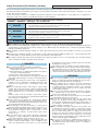
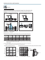
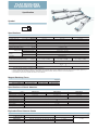
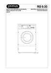
Vérin sans tige profil plat
à accouplement magnétique WRV
Jusqu' à
8mm/s
Magnet Type
Flat Rodless Cylinders WRV
Environmentally friendly
RoHS compliant product!
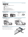
Unique oval barrel design enables good
low-speed performance, low center of
gravity, and non-rotating.
Low-Speed Performance
Basic
Type
Superior low-speed performance of 8mm/s.
Best performance among Magnet Type
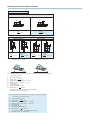
Plate bumper
(urethane rubber)
Rodless cylinders.
Direct Mounting
A block-type end plate makes
direct mounting possible.
Side surface
piping
Non-Rotating
Thin Design
Reduced by 30% in height
End surface
piping
With
Shock
Absorber
Specification
Side surface
piping
Non-Rotating
Shock Absorber
A dedicated linear orifice shock absorber installed.
Absorbs impacts softly without any adjustment.
Adjustable Stroke
Simple stroke adjustment, just by
moving the shock absorber.
Caution
Before use, be sure to read the “Safety Precautions” on p. .
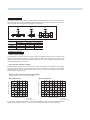
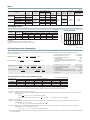
0RODUCT2ANGE
"ASIC4YPE
7ITH3HOCK!BSORBER
3PECIFICATION
/PTIONS
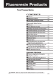
3ENSOR3WITC-TYPE-OUNT
By installing a sensor rail and sensor magnet, positioning
detection across the full stroke range is possible.
3TANDARD3TROKES
Model
WRV14
WRV22
WRV28
Combines with linear guide to reduce the height to a minimum, and also offers various connection with equipment.
INDEX
Stroke (mm)
100
150
200
250
300
350
400
450
500
600
700
800
Available
stroke
s
s
s
s
s
s
s
s
s
1∼1000
s
s
s
s
s
s
s
s
s
s
1∼1500
s
s
s
s
s
s
s
s
s
s
1∼1500
Features
Safety Precautions
Handling Instructions and Precautions
Specification List
Order Codes
Dimensions
Sensor Switches
Safety Precautions (Flat Rodless Cylinders)
Always read these precautions carefully before use.
Before selecting and using the products, please read all the Safety Precautions carefully to ensure proper product use.
The Safety Precautions shown below are to help you use the product safely and correctly, and to prevent injury or damage to you, other
people, and assets beforehand.
Follow the Safety Precautions for: ISO4414 (Pneumatic fluid power—Recommendations for the application of equipment to
transmission and control systems), JIS B 8370 (Pneumatic system regulations)
The directions are ranked according to degree of potential danger or damage:
“DANGER!”, “WARNING!”, “CAUTION!”, and “ATTENTION!”
DANGER
Expresses situations that can be clearly predicted as dangerous.
If the noted danger is not avoided, it could result in death or serious injury.
It could also result in damage or destruction of assets.
WARNING
Expresses situations that, while not immediately dangerous, could become dangerous.
If the noted danger is not avoided, it could result in death or serious injury.
It could also result in damage or destruction of assets.
CAUTION
Expresses situations that, while not immediately dangerous, could become dangerous.
If the noted danger is not avoided, it could result in light or semi-serious injury.
It could also result in damage or destruction of assets.
ATTENTION
While there is little chance of injury, this content refers to points that should be observed for
appropriate use of the product.
■This product was designed and manufactured as parts for use in General Industrial Machinery.
■ In the selection and handling of the equipment, the system designer or other person with fully adequate knowledge and experience
should always read the Safety Precautions, Catalog, User’s Manual and other literature before commencing operation. Making
mistakes in handling is dangerous.
■ After reading the Instruction Manual, Catalog, etc., always place them where they can be easily available for reference to users of this
product.
■ If transferring or lending the product to another person, always attach the Instruction Manual, Catalog, etc., to the product where they
are easily visible, to ensure that the new user can use the product safely and properly.
■ The danger, warning, and caution items listed under these “Safety Precautions” do not cover all possible cases. Read the Catalog
and User’s Manual carefully, and always keep safety first.
DANGER
● Do not use the product for the purposes listed below:
1. Medical equipment related to maintenance or management
of human lives or bodies.
2. Mechanical devices or equipment designed for the purpose
of moving or transporting people.
3. Critical safety components in mechanical devices.
This product has not been planned or designed for purposes
that require advanced stages of safety. It could cause injury to
human life.
● Do not use the product in locations with or near dangerous
substances such as flammable or ignitable substances. This
product is not explosion-proof. It could ignite or burst into
flames.
● When mounting the product and workpiece, always firmly
support and secure them in place. When mounting the Flat
Rodless cylinder, always mount it with an end plate tightened
with mounting bolts at four counterbore locations (left and
right).
Failure to firmly secure the end plate could result in separation of the connection between the cylinder barrel and the end
plate, leading to possible injury.
● Persons who use a pacemaker, etc., should keep a distance
of at least one meter [3.28ft.] away from the product. There is
a possibility that the pacemaker will malfunction due to the
strong magnet built into the product.
● Never attempt to remodel the product. It could result in
abnormal operation leading to injury, electric shocks, fire, etc.
● Never attempt inappropriate disassembly, assembly or repair
of the product relating to basic construction, or to its
performance or to functions. It could result in injury, electric
shocks, fire, etc.
● Do not splash water on the product. Spraying it with water,
washing it, or using it underwater could result in malfunction
of the product leading to injury, electric shocks, fire, etc.
● While the product is in operation, avoid touching it with your
hands or otherwise approaching too close. In addition, do not
make any adjustments to the interior or to the attached
e
mechanisms (sensor switch mounting location, disconnection
of piping tubes or plugs, etc.).
● The actuator can move suddenly, possibly resulting in injury.
● When operating the product, always install speed controllers,
and gradually loosen the needle valve from a choked state to
adjust the speed increasing. Failure to make this adjustment
could result in sudden movements, putting human lives at risk.
WARNING
● Do not use the product in excess of its specification range.
Such use could result in product breakdowns, function stop or
damage or drastically reduce the operating life.
● Before supplying air or electricity to the device and before
starting operation, always conduct a safety check of the area
of machine operation. Unintentional supply of air or electricity
could possibly result in electric shocks, or in injury caused by
contact with moving parts.
● Do not touch the terminals and the miscellaneous switches,
etc., while the device is powered on. There is a possibility of
electric shocks and abnormal operation.
● Do not allow the product to be thrown into fire. The product
could explode and/or release toxic gases.
● Do not sit on the product, place your foot on it, or place other
objects on it. Accidents such as falling and tripping over could
result in injury. Dropping the product may result in injury, or
also damage or break the product resulting in abnormal or
erratic operation, or runaway, etc.
● When conducting any kind of operation for the product, such
as maintenance, inspection, repair, or replacement, always
turn off the air supply completely and confirm that residual
pressure inside the product or in piping connected to the
product is zero before proceeding. In particular, be aware that
residual air will still be in the air compressor or air storage
tank. The actuator could abruptly move if residual air pressure
remains inside the piping, causing injury.
● Do not use the actuator for equipment whose purpose is
absorbing the shocks and vibrations of mechanical devices. It
could break and possibly result in injury or in damage to
mechanical devices.
heavy objects or excessive loads on them. Such action could
result in current leaks or defective continuity that lead to fire,
electric shocks, or abnormal operation.
scratching the cords for the sensor switch lead wires, etc.
s Avoid
Letting the cords be subject to scratching, excessive bending,
s
s
s
s
s
pulling, rolling up, or being placed under heavy objects or
squeezed between two objects, may result in current leaks or
defective continuity that lead to fires, electric shocks, or
abnormal operation.
Do not subject sensor switches to an external magnetic field
during actuator operation. Unintended movements could
result in damage to the equipment or in personal injury.
Use within the recommended load and operating frequency
specifications. Attempting to use beyond the recommended
load and operating frequency specifications could damage the
table, etc., which could result in damage to the equipment or
personal injury. It could also drastically reduce the product’s
operating life.
Use safety circuits or create system designs that prevent
damage to machinery or injury to personnel when the
machine is shut down due to an emergency stop or electrical
power failure.
Install relief valves, etc., to ensure that the actuator does not
exceed its rated pressure when such pressure is rising due to
external forces on the actuator. Excessive pressure could
lead to a breakdown and damage.
In initial operations after the equipment has been idle for 48
hours or more, or has been in storage, there is a possibility that
contacting parts may have become stuck, resulting in equipment
operation delays or in sudden movements. Before these initial
operations, always run a test to check that operating
performance is normal.
CAUTION
not use in locations that are subject to direct sunlight
s Do
(ultraviolet rays), dust, salt, iron powder, humidity, or in the
s
s
s
s
s
s
s
media and/or the ambient atmospheres that include organic
solvents, phosphate ester type hydraulic oil, sulphur dioxide,
chlorine gas, acids, etc. It could lead to early shutdown of
function or a sudden degradation of performance, and result
in a reduced operating life. For the materials, see the Major
Parts and Materials.
When mounting the product, leave room for adequate working
space around it. Failure to ensure adequate working space
will make it more difficult to conduct daily inspections or
maintenance, which could eventually lead to system
shutdown or damage to the product.
Do not bring floppy disks or magnetic media, etc., within one
meter [3.28ft.] of the product. There is the possibility that the
data on the floppy disks will be destroyed due to the
magnetism of the magnet.
Do not use the sensor switch in locations subject to large
electrical currents or strong magnetic fields. It could result in
erratic operation. In addition, do not use magnetized materials
in the mounting bracket. The magnetism could leak, possibly
resulting in erratic operation.
Do not bring the product too close to a magnetic body.
Positioning it near a magnetic body or strong magnetic field
will cause erratic operation of sensor switches due to
magnetization of the main body and table, or cause failure by
adherence of iron powder, etc.
Never use other companies’ sensor switches with these
products. It could possibly cause error or accidental operation.
Do not scratch, dent, or deform the actuator by climbing on
the product, using it as scaffold, or placing objects on top of it.
It could lead to damaged or broken products that result in
operation shutdown or degraded performance.
Always post an “operations in progress” sign for installations,
adjustments, or other operations, to avoid unintentional
supplying of air or electrical power, etc. Such accidental
supplies may cause electrical shocks, or sudden activation of
the actuator that could result in physical injury.
Do not pull on the cords of the lead wires, etc., of the sensor
switches mounted on the actuators, grab them to lift, or place
s
ATTENTION
When considering the possibility of using this product in
ssituations
or environments not specifically noted in the
s
s
s
s
s
s
s
Catalog or User’s Manual, or in applications where safety is
an important requirement such as in an airplane facility,
combustion equipment, leisure equipment, safety equipment
and other places where human life or assets may be greatly
affected, take adequate safety precautions such as the
application with enough margins for ratings and performance
or fail-safe measure. Be sure to consult us with such
applications.
Always check the Catalog and other reference materials for
product wiring and piping.
Use a protective cover, etc., to ensure that the operating parts
of mechanical devices, etc., are isolated and do not come into
direct contact with human bodies.
Do not control in a way that would cause workpieces to fall
during a power failure. Take control measures so that they
prevent the table or workpieces, etc., from falling during a
power failure or emergency stop of the mechanical devices.
When handling the product, wear protective gloves, safety
glasses, safety boots, etc., to keep safety.
When the product can no longer be used, or is no longer
necessary, dispose of it appropriately as industrial waste.
Pneumatic equipment can exhibit degraded performance and
function over its operating life. Always conduct daily
inspections of the pneumatic equipment, and confirm that all
requisite system functions are satisfied, to prevent accidents
from happening.
For inquiries about the product, consult your nearest Automax
sales office or Automax overseas department. The address
and telephone number is shown on the back cover of this
catalog.
OTHERS
observe the following items.
s Always
1. When using this product in pneumatic systems, always use
genuine Automax parts or compatible parts (recommended parts).
When conducting maintenance and repairs, always use
genuine Automax parts or compatible parts (recommended parts). Always observe the required methods
and procedure.
2. Never attempt inappropriate disassembly or assembly of
the product relating to basic configurations, or its
performance or functions.
Automax cannot be responsible if these items are not properly
observed.
Safety Precautions (Sensor Switches)
Always read these precautions carefully before use.
Design and selection
Installation and adjustment
Warning
Warning
1.Check the specifications.
As use of this product over the specified ranges of voltage,
current, temperature, shocks, etc., could result in a
breakdown or abnormal operation, always read the
specifications carefully to ensure correct use.
2.Avoid mounting actuators in close proximity.
Mounting two or more actuators with sensor switches in close
proximity could result in erratic operation of the sensor
switches, due to magnetic field interference with the system.
3.Caution about sensor switch ON time for positioning detection at intermediate stroke position.
Take caution that if the sensor switch is mounted at an
intermediate position of the actuator stroke for detection of
the piston travel, the sensor switch actuation time may be too
short when the actuator speed is very rapid, so that the load
(sequencer, etc.) may fail to activate.
Maximum cylinder speed for positioning detection
V (mm/s) [in./sec.] =
Sensor switch actuation range (mm) [in.]
Time required for activating load (ms)
1000
4.Keep wiring as short as possible.
The solid state sensor switch lead wire length should be within
30m [98ft.] as stipulated in the EN standards. For the reed
sensor switch, if the lead wire is too long (10m [33ft.] or more),
capacitive surges will shorten the operating life of the sensor
switch. If long wiring is needed, install the protection circuit
mentioned in the catalog. If the load is inductive or capacitive,
also install the protection circuit mentioned in the catalog.
5.Avoid repeated or excessive bending or pulling of
lead wires.
Applying repeated bending stress or tension force on the lead
wire could result in wire breakage.
6.Check for leakage current.
5.2-lead wire solid state sensor switches produce leakage
current to activate their internal circuits, and the current
passes through a load even when in the turned-off condition.
Ensure they satisfy the following inequality.
Input off current of programmable controller > Leakage current
If the above inequality cannot be satisfied, select a 3-lead
wire solid state sensor switch, instead. Also note that parallel
connection of a total of N sensor switches will multiply the
amount of leakage current by N times.
Caution
1.Check for sensor switch internal voltage drop.
Series connection of reed sensor switches with indicator
lamps or 2-lead wire solid state sensor switches causes
increasing internal voltage drop, and the load may fail to
activate. A total of N sensor switches will lead to N times the
internal voltage drop. Ensure that the system satisfies the
following inequality.
Supply voltage – Internal voltage drop N
operating voltage for load
>
Minimum
In relays with rated voltage of less than DC24V, check to see
whether the above inequality is satisfied, even in the case of
N = 1. If the above inequality cannot be satisfied, select a reed
sensor switch without indicator lamp.
2.Do not use our sensor switches with other
companies’ actuators.
The sensor switches are designed for use with Automax
actuators only. Use with other companies’ actuators could
lead to abnormal operation.
1.Do not apply an external magnetic field to the sensor
switch while the actuator is in operation.
An unintended movement could result in damage to the
equipment or in personal injury.
Caution
1.Ensure a safe installation environment for the
actuators with sensor switches.
Do not use sensor switches in places where large current or
magnetic fields are present. This could lead to unintentional
operation. Do not use magnetic material for the mounting
brackets. It could result in erratic operation.
2.Install sensor switches in the center of their operating
range.
Adjust the mounting position of a sensor switch so that the
piston stops in the center of its operating range (the range
while the sensor turns ON). Operations will be unstable if
mounted at the end of the operating range (at the boundary
near ON and OFF). Also be aware that the operating range
will vary with changes in temperature.
3.Follow the tightening torque of sensor switches
when mounting.
Over-tightening beyond the allowed tightening torque may
damage the mounting threads, mounting brackets, sensor
switches, etc. In addition, insufficient tightening torque could
cause the sensor switch position to be changed, resulting in
operation instability. For the tightening torque, follow the
instructions on p. .
4.Do not carry the actuator grabbing its sensor switch
lead wires.
After mounting a sensor switch to an actuator, do not grab and
lift the lead wires to carry the actuator. Never do this, as it
could result in lead wire disconnections, and could also apply
stress to the interior of the sensor switch, resulting in breakage
of internal elements.
5.Do not drop sensor switches, or bump them against
others.
During handling of sensor switches, do not apply excessive
shocks (294.2m/s2 [965ft./sec.2] {30G} or larger) such as hitting,
dropping, or bumping. In reed sensor switches, the contact
reed may be activated unintentionally, causing it to send or
break sudden signals. It may also cause changes in the
contact interval that lead to changes in sensor switch
sensitivity and result in erratic operation. Even if the sensor
switch case is undamaged, the inner parts of the sensor
switch may suffer breakdown or cause erratic operation.
Handling Instructions and Precautions
General precautions
Wiring
Danger
1.Avoid letting moving objects near sensor switches
come into contact with them.
When the actuators with sensor switches are moving, or when
moving objects are nearby, do not let them come into contact
each other. In particular, lead wires could become worn out or
damaged, causing operating instability in the sensor switch. In the
worst case, it could result in current leaks or electrical shocks.
2. Always turn off the power supply for wiring work.
Conducting wiring work while the power is on could result in
electric shocks. Also, incorrect wiring could damage sensor
switches in an instant. Turn on the power only after the wiring
work is completed.
Warning
1.Check the Catalog, etc., to ensure that the sensor
switch wiring is correctly connected.
Miswiring could result in abnormal operation.
2.Do not share the same wiring with power or high
voltage lines.
Avoid wiring in parallel to or shared with power or high voltage
lines. The sensor switch or control circuit may suffer electric
noise that results in erratic operation.
3.Avoid repeated or excessive bending or pulling of
lead wires.
Applying repeated bending stress or tension force on the lead
wire could result in wire breakage.
4. Check polarity in the wiring.
In sensor switches that specify polarity (+, –, output), be sure
that wiring connections are correct. The wrong polarity could
result in damage to sensor switches.
Caution
1. Avoid short circuiting the loads.
Turning a sensor switch on while the load is short-circuited
causes overcurrent, which will damage the sensor switch in
an instant.
Example of short-circuited load: Sensor switch’s output lead
wire is directly connected to the power supply.
Media
1. Use air for the media. For the use of any other media, consult
us.
2. Air used for the Flat Rodless cylinders should be clean air that
contains no deteriorated compressor oil, etc. Install an air filter
(filtration of 40 μm or less) near the Flat Rodless cylinders or
valve to remove collected liquid or dust. In addition, drain the
air filter periodically. Collected liquid or dust entering the Flat
Rodless cylinder may cause improper operation.
Piping
1. In piping connection with the Flat Rodless cylinders, flush the
tube completely (by blowing compressed air) before piping.
Intrusion of machining chips, sealing tape, rust, etc.,
generated during plumbing could result in air leaks and other
defective operations.
2. When screwing in piping or fittings to the Flat Rodless
cylinders, tighten to the appropriate tightening torque shown
below.
Connecting thread
Tightening torque N・m {kgf・m} [ft・lbf]
M5 0.8
1.6 {0.16} [1.2]
Rc1/8
6.9∼8.8 {0.69∼0.88} [5.1∼6.5]
Atmosphere
1. When using in locations subject to dripping water, dripping
oil, etc., or to large amounts of dust, use a cover to protect
the unit.
2. The product cannot be used when the media or ambient
atmosphere contains any of the substances listed below.
Organic solvents, phosphate ester type hydraulic oil, sulphur
dioxide, chlorine gas, or acids, etc.
Lubrication
The Flat Rodless cylinders can be used without lubrication. If
lubrication is required, however, always consult us first. Do not
use turbine oil.
Others
1. When the Flat Rodless cylinder is moved manually, its
movement may not feel smooth. This is not a problem,
however, since it is normally operated using air pressure.
Always apply air to the system to check its operation.
2. The Flat Rodless cylinder has a strong magnet integrated
into its body. Do not place magnetic media, recording
devices, magnetic detection devices, etc., within 1 meter
[3.28ft.] of the product. This could result in lost data or erratic
operation.
Handling Instructions and Precautions
Selection
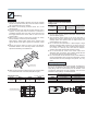
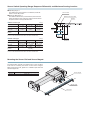
Allowable load and moment
Although the Flat Rodless cylinders can be used with directly applying loads, make sure that the load
and moment do not exceed the values in the table below. In addition, since load capacity may vary
depending on the speed, confirm the rubber bumper and shock absorber absorption capacity on p.
before use.
-P&PR
-R&RR
&P
&R
R
R
-Y&YR
7 &Y
R
7 Pitching moment
Rolling moment
Yawing moment
Maximum load capacity
7 : Mp=Fp r1(N·m)
: Mr=Fr r2 (N·m)
: My=Fy r3 (N·m)
: W1,W2,W3 (N)
Note: External forces Fp and Fy should be restricted to 60% or less of the magnet retaining force.
Direction of
moment
Mp
N・m {kgf・m}
[ft・lbf]
Mr
N・m {kgf・m}
[ft・lbf]
My
N・m {kgf・m}
[ft・lbf]
WRV14
1.2 {0.1} [0.9]
0.3 {0.03} [0.2]
1.2 {0.1} [0.9]
130 1{3}1 [6.7] 130 1{3}1 [6.7]
10 {1}.5 1[2.2]
WRV22
4.1 {0.4} [3.0]
1.1 {0.1}1 [0.7]
4.1 {0.4} [3.0]
180 1{8} [18.0] 180 1{8} [18.0]
30 {3}.5 1[6.7]
WRV28
8.1 {0.8} [5.9]
2.1 {0.2}1 [1.5]
8.1 {0.8} [5.9]
120 {12} [27.0] 120 {12} [27.0]
45 {4.5} [10.1]
Model
W1 Note
W2 Note
W3 Note
N {kgf} [lbf.]
N {kgf} [lbf.]
N {kgf} [lbf.]
Caution: The moment including the inertial force generated when the load is moved or stopped
must not exceed the values in the above table.
Keep the mass and speed within the range of the rubber bumper and shock absorber
capacity graphs.
Note: W is the maximum value. Since W varies depending on the stroke, use it within the
“Maximum load capacity and stroke” ranges shown in the graph below.
s Maximum load capacity and stroke
s Relationship between load capacity and air pressure during vertical operation (reference)
Load capacity during
ver tical operation
Maximum load capacity
150
100
WRV28
50
WRV22
7 7 (.).OTE
WRV28
7
WRV22
WRV14
0
0
500
1000
Cylinder stroke (mm)
Note: The value for W3 is 1/3 that of W1 and W2.
1500
1N = 0.225lbf.
1mm= 0.0394in.
R
7 (.)
WRV14
Bending moment
When M=0
Maximum value
When M=
2
When M=Maximum value
Air pressure (MPa)
1N = 0.225lbf.
1MPa= 145psi.
Bending moment
M=WR
Slider deflection
The reference values of the amount of slider deflection due to clearance is shown in the table below.
Since the slider portion of the Flat Rodless cylinder allows a certain amount of play as shown below,
use the cylinder with a linear guide in high-precision applications.
-P
-R
-Y
α α α α α α Slider deflection (¼α°)
Model
Mp direction
Mr direction
My direction
WRV14
0.8
1.8
0.8
WRV22
0.6
1.2
0.6
WRV28
0.7
1.3
0.7
Cushioning capacity
s Rubber bumper capacity
The Flat Rodless cylinders come with rubber bumpers as standard equipment. The maximum load
capacity and impact speed, however, should lie within the “With rubber bumper” range shown in the
“Rubber bumper and shock absorber capacity graph” below. Do not use it when the maximum impact
speed exceeds 500mm/s [19.7in./sec.].
s Shock absorber absorption capacity
The Flat Rodless cylinders use shock absorbers as optional equipment. The maximum load capacity
and impact speed, however, should lie within the “With shock absorber” range shown in the “Rubber
bumper and shock absorber capacity graph” below. Do not use it when the maximum impact speed
exceeds 800mm/s [31.5in./sec.].
s Rubber bumper and shock absorber capacity graph
(Horizontal operation, at air pressure of 0.5MPa [73psi.])
s With rubber bumper
s With shock absorber
120
140
WRV28
Maximum load capacity (N)
Maximum load capacity (N)
140
100
80
WRV22
60
40
WRV14
20
0
100
200
300
400
500
Impact speed (mm/s)
600
1N = 0.225lbf.
1mm/s= 0.0394in./sec.
120
WRV*28CVA
100
80
WRV*22CVA
60
40
WRV*14CVA
20
0
100
200
300
400
500
600
Impact speed (mm/s)
700
800
900
1N = 0.225lbf.
1mm/s= 0.0394in./sec.
In the graphs, “Impact speed” refers to the speed immediately before the slider impacts the rubber
bumper or shock absorber. This is not the same as “average speed (cylinder stroke/travel time)”.
Handling Instructions and Precautions
Calculation of impact energy
Horizontal impact
'
,
M
L'
W'
&O
F'o
E=E1+E2
m・V2
=
2 +FO・L
Eg =Eg 1+Eg 2
Wg ・Vg 2
= 2gg +Fg O・Lg
Vertical impact Note 1
'
%=% +% +% M・V
=
+& /・,+M・G・,
Eg =Eg 1+Eg 2+Eg 3
Wg ・Vg 2
= 2gg +Fg O・Lg +Wg・Lg
Note 1: For impact on incline,
E3 becomes E3g = m・g・L・sin .
&O
M
%=% +% −% M・V
=
+& /・,−M・G・,
'
Eg =Eg 1+Eg 2−Eg 3
Wg ・Vg 2
= 2gg +Fg O・L−Wg ・Lg
Note 1: For impact on incline,
Eg 3 becomes Egg 3= Wg・Lg・sin .
M
&O
F'o W'
L'
,
L'
,
F'o W'
M
&O
When ascending
When descending
Note 2
W'
F'o
Note 2: When descending, heavier loads can be carried using lower operating air pressure (P)
than when ascending.
E :Total impact energy x [J]
m・V
E1 :Kinetic energy x
[J]
2
E2 :Additional energy by cylinder thrust xFo·L [J]
E3 :Additional energy by load mass xm·g·L [J]
m :Load mass [kg]
V :Impact speed [m/s]
g :Gravity acceleration 9.8 [m/s2]
Fo :Cylinder thrust x = ·D2·P [N]
4
Fo :[D: Cylinder bore (mm) P: Operating air pressure (MPa)]
L :Absorbing stroke of shock absorber [m]
Note 2: When descending, heavier loads can be carried using lower operating air
pressure (Pg ) than when ascending.
Eg :Total impact energy x [ft·lbf]
Wg・Vg 2
[ft·lbf]
Eg 1 :Kinetic energy x
2gg
Eg 2 :Additional energy by cylinder thrust xFgo·Lg [ft·lbf]
Eg 3 :Additional energy by load weight xWg · Lg [ft·lbf]
Wg :Load weight [lbf]
Vg :Impact speed [ft./sec.]
gg :Gravity acceleration 32.2 [ft./sec.]
Fgo:Cylinder thrust x = ·Dg 2·Pg [lbf.]
4
Fo :[Dg : Cylinder bore [in.] Pg : Operating air pressure [psi.]]
Lg :Absorbing stroke of shock absorber [ft.]
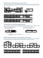
Mounting
Mounting
Mounting the shock absorber
1. Because the Flat Rodless cylinders have strong magnets
built into the cylinder bodies, they cannot be used in locations
with magnetized cutting oil or powder.
2. Be careful to avoid making scratches, dents, etc., on the
cylinder barrel.
3. If an external force larger than the magnetic retaining force is
applied, causing the slider and piston to deviate or
completely separate, return the piston to the stroke end and
then apply external force to the slider to restore it to the
correct position.
4. When using in locations where the cylinder can easily
become smeared, clean the cylinder periodically.
After cleaning, always apply grease to the surface of the
cylinder barrel. For the type of grease to be applied, consult
us.
5. Mount the cylinder barrel so that it cannot be twisted.
Insufficient flatness of the mounting surface could result in
cylinder barrel twisting and malfunctions.
Tightening torque for shock absorber
hexagon nuts
Model
Tightening
torque
For WRV14
+3(*-
For WRV22
+3(*-
2.5 {25} [1.8]
N・m {kgf・cm} [ft・lbf]
For WRV28
+3(*-
6.5 {65} [4.8]
1. Use the shock absorber within its absorption capacity range
(from its capacity graph).
2. The maximum impact speed to the shock absorber is
800mm/s [31.5 in./sec.]. Note that this is not the same as the
average speed. The speed at time of impact should not
exceed 800mm/s [31.5 in./sec.].
3. Do not use the shock absorber in a place subject to large
amounts of dripping water, dripping oil, or dust. If using it in
these places, install a cover, etc., so that the liquid drops etc.
do not drip on it directly. This could lead to improper
operation and might decrease the absorption energy.
4. Do not loosen the set screw on the center of the shock
absorber’s back end surface. The oil sealed inside will leak
out, which will cause the shock absorber to fail.
5. Do not install other shock absorbers in this product. Because
product characteristics vary among shock absorbers, if other
shock absorbers are used, damage to the cylinder, etc., may
occur.
Size of piping materials
Cylinder barrel
6. When mounting the body, always secure it by mounting bolts
at 4 counterbore holes on the end plate (left and right).
Tightening torque
N・m {kgf・cm} [ft・lbf]
For the side surface port with a sensor rail type, the distance to
the sensor rail determines the outer diameter of the attached
piping fitting, while for an end surface port, the diameter of the
counterbore determines the outer diameter. For the outer
diameters of piping fittings, use the below table.
Model
Side surface (with sensor rail)
End surface
A
B
WRV22
WRV28
WRV14
10 [0.394in.]
10 [0.394in.]
Tightening
torque
2.8 {28} [2.1]
(-)
6 {60} [4.4]
(-)
10 {100} [7.4]
(-)
WRV22
13 [0.512in.]
10 [0.394in.]
WRV28
16 [0.630in.]
4-Counterbore holes
B
WRV14
A
Model
FLAT RODLESS
CYLINDERS WRV
Specification
Symbol
Specifications
Item
Equivalent bore size
Model
WRV14
WRV22
WRV28
mm [in.]
;=
;=
;=
Media
Air Note1
Operating type
Double acting type
Operating pressure range
MPa {kgf/cm2} [psi.]
Proof pressure
MPa {kgf/cm2} [psi.]
1.05 {10.7} [152]
°C [°F]
0∼60 [32∼140]
Operating temperature range
0.2∼0.7 {2∼7.1} [29∼102]
8∼500 [0.31∼19.7] Note2
Basic type
Operating speed range
mm/s [in./sec.] With shock absorber specification
8∼800 [0.31∼31.5] Note2
Basic type
Cushion
Rubber bumper
Shock absorber
With shock absorber specification
Lubrication
Not required Note3
Stroke adjusting range (with shock absorber specification only)
(per one side in specification stroke)
mm [in.]
Maximum stroke
mm
Stroke tolerance
mm [in.]
0∼−10 [0∼−0.394]
0∼−15 [0∼−0.591]
1500 Note4
[
]
+2 +0.079
0 +0.079
Port size
Notes: 1.
2.
3.
4.
0∼−6 [0∼−0.236]
-
2C
Use clean air that contains no moisture, dust, and oxidized oil.
For the relationship between the maximum load capacity and the impact speed, see the “Rubber bumper and shock absorber capacity graph” on p. .
This product can be used without lubrication. If lubrication is required, however, always consult us. Do not use turbine oil.
The maximum stroke of the cylinder with sensor rail is 1000mm.
Magnet Retaining Force
N {kgf} [lbf.]
Model
Item
Retaining force
WRV14
WRV22
WRV28
115 {11.7} [25.9]
310 {31.6} [69.7]
500 {51} [112]
Specifications of Shock Absorber
Model
Item
Applicable shock absorber
Maximum absorption J {kgf·m} [ft·lbf]
Absorbing stroke
WRV*14CVA
WRV*22CVA
WRV*28CVA
KSHJM 8 5-14
KSHJM 8 5-22
KSHJM 10 10-28
1.5 {0.15} [1.1]
3 {0.3} [2.2]
1 {0.1} [0.7]
mm [in.]
10 [0.394]
5 [0.197]
Maximum impact speed mm/s [in./sec.]
800 [31.5]
Maximum operating frequency cycle/min
60
Spring return force (compressed) N {kgf} [lbf.]
6 {0.6} [1.3]
{};=
Angle variation
1° or less
Operating temperature range °C [°F]
0∼60 [32∼140]
Note: The life of the shock absorber may vary from the Flat Rodless cylinder, depending on its operating condition.
Equivalent Bore Size and Stroke
Item
Model
WRV(*)14CV*
Standard strokes
100, 150, 200, 250, 300, 350, 400, 450, 500
Maximum available stroke
1∼1000
WRV(*)22CV*
200, 250, 300, 350, 400, 450, 500, 600, 700, 800
1∼1500
WRV(*)28CV*¬
200, 250, 300, 350, 400, 450, 500, 600, 700, 800
1∼1500
Remark: Non-standard strokes are available at 1mm intervals.
MM
Maximum available stroke with sensor rail
1∼1000
Mass
kg [oz.]
Zero stroke
mass
Model
WRV(*)14CV
WRV(*)22CV
WRV(*)28CV
0.22 1 [7.76]
Basic type: K
With shock absorber:A 0.27 1 [9.52]
0.50 [17.64]
Basic type: K
With shock absorber:A 0.59 [20.81]
0.86 [30.34]
Basic type: K
With shock absorber:A 1.00 [35.27]
Shock absorber unit
Additional
mass for each
1mm [0.0394in.]
stroke
One side
M-type
mount
Both sides
0.017 [0.60]
0.000267
[0.00942]
10.01 [0.35] 10.02 [0.71]
0.000491
[0.01732]
10.01 [0.35] 10.02 [0.71]
0.000656
[0.02314]
0.022 [0.78] 0.044 [1.55]
Sensor switch
0.0001
[0.0035]
0.035
[1.23]
0.008
[0.28]
0.004
[0.14]
0.052 [1.83]
Additional mass
for each
1 mm [0.0394in.]
sensor rail
Lead wire
3m [118in.]
0.007
[0.25]
10.03 [1.06]
Sensor
magnet
Zero stroke
mass of
sensor rail
0.010
[0.35]
Theoretical Thrust
N [lbf.]
Thrust efficiency
Air pressure MPa
0.2 [29]
;=
;=
;=
;=
;=
WRV14
157 [0.243]
131 1[7.0]
147 [10.6]
163 [14.2]
179 [17.8]
194 [21.1]
110 [24.7]
WRV22
402 [0.623]
180 [18.0]
121 [27.2]
161 [36.2]
201 [45.2]
241 [54.2]
281 [63.2]
WRV28
628 [0.973]
126 [28.3]
188 [42.3]
251 [56.4]
314 [70.6]
377 [84.7]
440 [98.9]
The figures in the table are theoretical values. There may be some difference from these for practical
applications.
For actual selection, see the thrust efficiency at left.
Note that thrust efficiency tends to be lower at low pressure.
100
Thrust efficiency (%)
Model
Pressure area
mm2 [in.2]
50
0.1
0.2
0.3
0.4
0.5
0.6
0.7
Air pressure (MPa)
1MPa = 145psi.
Air Flow Rate and Air Consumption
While the Flat Rodless cylinder’s air flow rate and air consumption can be found through the following calculations, the quick reference table below provides the
answers more conveniently.
Q1 : Required air flow rate for cylinder
2 /min (ANR)
Q2 : Air consumption of cylinder
2 /min (ANR)
π D2
60
P+0.101
–6
Air flow rate: Q 1=
L
10
mm
D : Cylinder equivalent bore size
4
t
0.101
mm
L : Cylinder stroke
t : Time required for cylinder to travel 1 stroke
s
π D2
P+0.101
n : Number of cylinder reciprocations per minute times/min
Air consumption: Q 2=
L 2 n
10 –6
4
0.101
P : Pressure
MPa
Air flow rate: Q1g = π Dg
4
2
Lg
Q 1g : Required air flow rate for cylinder
ft.3/min. (ANR)
Q 2g : Air consumption of cylinder
ft.3/min. (ANR)
Dg : Cylinder equivalent bore size
in.
Lg : Cylinder stroke
in.
sec.
t : Time required for cylinder to travel 1 stroke
n : Number of cylinder reciprocations per minute times/min
Pg : Pressure
psi.
60
1
Pg +14.70
1728
t
14.70
Air consumption: Q 2g = π Dg Lg 2 n
4
2
1
Pg +14.70
1728
14.70
Air consumption for each 1 mm [0.0394in.] stroke
Equivalent bore
size mm [in.]
cm3 [ft.3]/Reciprocation (ANR)
Air pressure MPa [psi.]
0.2 [29]
0.3 [44]
0.4 [58]
0.5 [73]
0.6 [87]
0.7 [102]
14 [0.551]
0.936 [3.311 10–5] 1.246 [4.401 10–5] 1.558 [5.501 10–5] 1.868 [6.601 10–5] 2.180 [7.701 10–5] 2.490 [8.791 10–5]
22 [0.866]
2.396 [8.461 10–5] 3.192 [1.127 10–4] 3.988 [1.408 10–4] 4.784 [1.689 10–4] 5.580 [1.971 10–4] 6.378 [2.252 10–4]
28 [1.102]
3.744 [1.322 10–4] 4.988 [1.761 10–4] 6.232 [2.201 10–4] 7.476 [2.640 10–4] 8.720 [3.079 10–4] 9.966 [3.519 10–4]
The figures in the table are for computing the air flow rate and air consumption when a Flat Rodless cylinder makes 1 reciprocation
with stroke of 1mm [0.0394in.]. The air flow rate and air consumption actually required are found by the following calculations.
s Finding the air flow rate (for selecting F.R.L., valves, etc.)
Example:
When operating a Flat Rodless cylinder of an equivalent bore size of 22mm [0.866in.] at a speed of 300mm/s [11.8in./sec.] under air pressure of
0.5MPa [73psi.]
1
4.784
300 10−3=0.712 /s [0.025ft.3/sec.] (ANR)
2
1
(At this time, the flow rate per minute is 4.784
300 60 10−3=43.052 /min [1.52ft.3/min.] (ANR))
2
s Finding the air consumption
Example 1. When operating a Flat Rodless cylinder of an equivalent bore size of 22mm [0.866in.] and a stroke of 100mm [3.94in.] under air pressure of
0.5MPa [73psi.], for 1 reciprocation
Example 2.
4.784 100 10−3=0.4782 [0.0169ft.3]/Reciprocation (ANR)
When operating a Flat Rodless cylinder of an equivalent bore size of 22mm [0.866in.] and a stroke of 100mm [3.94in.] under air pressure of
0.5MPa [73psi.], for 10 reciprocations per minute
4.784 100 10 10−3=4.782 min [0.169ft.3/min.] (ANR)
Note: To find the actual air consumption required when using the Flat Rodless cylinder, add the air consumption of the piping to the air consumption obtained from
the above calculation.
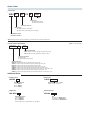
Order Codes
s Basic type
WRV P
14
CV K
200
Stroke
Cushion type
K : With rubber bumper
A : With shock absorber
Equivalent bore size
Magnet type
P : Without sensor rail & magnet
M : With sensor rail (Including sensor magnet)
Flat Rodless cylinder
with rubber bumper Note
Note: An M-type mount cannot be installed on a cylinder with shock absorber specification.
s Sensor switch specification
XEZE1 D - M8
Note: To order separately
Lead wire termination
Blank : Without connector (length wire: 3000mm [118in.])
M8: With M8 connector (length wire: 300mm [11.8in.])
Lead wire orientation
D : Right output
L : Bent output (with angle 90°)
Sensor switch type
XEZE1D: 2-lead wire solid state type with indicator lamp DC10 ~28V
XEZE1L: 2-lead wire bent output solid state type with indicator lamp DC10 ~28V
XEZ31D: 3-lead wire solid state type with indicator lamp DC4.5 ~28V
XEZ31L: 3-lead wire bent outputsolid state type with indicator lamp DC4.5 ~28V
XRZE0D: 2-lead wire reed switch type without indicator lamp DC5 ~28V, AC85 ~115V
XRZE0L: 2-lead wire bent output reed switch type without indicator lamp DC5 ~28V, AC85 ~115V
XRZE1D: 2-lead wire reed switch type with indicator lamp DC10 ~28V, AC85 ~115V
XRZE1L: 2-lead wire bent output reed switch type with indicator lamp DC10 ~28V, AC85 ~115V
Additional Parts
s M-type mount
M-WRV
Equivalent bore size
14 : For WRV14
22 : For WRV22
28 : For WRV28
s Magnet set
MG-WRV
Equivalent bore size
14 : For WRVM14
22 : For WRVM22
28 : For WRVM28
(Sensor magnet 1pc., magnet holder 1pc., bolt 2pcs.)
s Sensor rail
S-WRV
Equivalent bore size stroke
(Sensor rail 1pc., bolt 2pcs.)
s Shock absorber
KSHJM
Size
18×5-14 : For WRVP14CVA
18×5-22 : For WRVP22CVA
10×10-28 : For WRVP28CVA
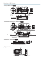
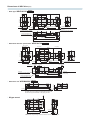
Dimensions of WRV*14 mm [in.]
s Basic type WRVP14CVK Stroke
41 [1.614]
24.6 [0.969]
34 [1.339]
44 [1.732]
30 [1.181]
4-M4×0.7 Depth6 [0.236]
72 [2.835]+Stroke
5 [0.197]
2-M5×0.8
Connection port (left chamber)
(with 1 plug)
4-M2×0.4 Depth5 [0.197]
For mounting sensor rail
4-φ4.8 [0.189]
5
[0.197] φ8 [0.315] Counterbore
Depth4.5 [0.177]
11.6 [0.457]
23 [0.906]
25 [0.984]
8.5 [0.335]
47 [1.850]
2 [0.079]
41 [1.614]
Stroke
44 [1.732]
30 [1.181]
23 [0.906]
13.5 [0.531]
2-M5×0.8
Connection port (right chamber)
(with 1 plug)
4-M2×0.4 Depth4 [0.157]
For mounting sensor magnet
52 [2.047]+Stroke
82 [3.228]+Stroke
9.5 [0.374]
15
[0.591]
9.5 [0.374]
15
[0.591]
s With shock absorber specification WRVP14CVA Stroke
31.5 [1.240]
30 [1.181]
24.6 [0.969]
34 [1.339]
44 [1.732]
30 [1.181]
4-M4×0.7 Depth6 [0.236]
72 [2.835]+Stroke
5 [0.197]
4 [0.157]
25.5 [1.004]
M8×0.75 13 [0.512] MAX.
□
41 [1.614]
Stroke
44 [1.732]
2-M5×0.8
Connection port (left chamber)
(with 1 plug)
4-M2×0.4 Depth4 [0.157]
For mounting sensor magnet
52 [2.047]+Stroke
82 [3.228]+Stroke
9.5 [0.374]
15
[0.591]
4-M2×0.4 Depth5 [0.197]
For mounting sensor rail
11.6 [0.457]
2 [0.079] 31 [1.220]
33 [1.299]
41 [1.614]
8.5 [0.335]
47 [1.850]
23 [0.906]
13.5 [0.531]
4-φ4.8 [0.189]
5
φ8 [0.315] Counterbore
[0.197]
Depth4.5 [0.177]
13 [0.512] MAX.
2-M5×0.8
9.5 [0.374] Connection port (right chamber)
15
[0.591]
(with 1 plug)
2.5 [0.098]
77 [3.031]+Stroke
2.5
[0.098]
1 [0.039] 7 [0.276]
s With sensor rail WRVM 14CVK Stroke
7.2 [0.283]
The “With sensor rail” model is shipped with the sensor rail
and sensor magnet assembled on the piping port side.
51 [2.008]
57 [2.244]
56 [2.205]
34 [1.339]
±1
[±0.039]
s M-type mount
1 [0.039]
4-M3×0.5
Depth7 [0.276]
7 [0.276]
26 [1.024]
Note: When using an M-type mount, be sure to remove the plate bumper.
Dimensions of WRV*22 mm [in.]
s Basic type WRVP22CVK
Stroke
46 [1.811]
9.7 [0.382]
58 [2.283]
61 [2.401]
2 [0.079] 29 [1.142]
4-M5×0.8Depth9 [0.354]
40 [1.575]
6 [0.236]
31 [1.220]
52 [2.047]
Stroke
58 [2.283]
38 [1.496]
52 [2.047]
16.5 [0.650]
37 [1.457]
29 [1.142]
4-φ5.8 [0.228]
6
φ9.5 [0.374] Counterbore, Depth5.5 [0.217]
[0.236]
2-M5×0.8
Connection port (right chamber)
(with 1 plug)
92 [3.622]+Stroke
17.6
[0.693]
2-M5×0.8
Connection port (left chamber)
(with 1 plug)
4-M2×0.4 Depth5 [0.197]
For mounting sensor rail
4-M2×0.4 Depth4 [0.157]
For mounting sensor magnet
68 [2.677]+Stroke
104 [4.094]+Stroke
11.5 [0.453]
18
[0.709]
s With shock absorber specification WRVP22CVA
11.5 [0.453]
18
[0.709]
Stroke
38.5 [1.516]
38 [1.496]
40 [1.575]
40 [1.575]
6 [0.236]
37 [1.457]
4-M5×0.8 Depth9 [0.354]
9 [0.354]MAX.
5 [0.197]
9 [0.354] MAX.
17.6
[0.693]
2-M5×0.8
Connection port (left chamber)
(with 1 plug)
18
[0.709]
Stroke
94 [3.701]+Stroke
5
[0.197]
2.5 [0.098] 7 [0.276]
5 [0.197]
2-M5×0.8
Connection port (right chamber)
4-M2×0.4 Depth4 [0.157]
11.5 [0.453] (with 1 plug)
For mounting sensor magnet
68 [2.677]+Stroke
18
104 [4.094]+Stroke
[0.709]
11.5 [0.453]
4-M2×0.4 Depth5 [0.197]
For mounting sensor rail
s With sensor rail WRVM22CVK
4-φ5.8 [0.228]
6
φ9.5 [0.374] Counterbore, Depth5.5 [0.217]
[0.236]
92 [3.622]+Stroke
32
[1.260]
M8×0.75
46 [1.811]
9.7 [0.382]
58 [2.283]
61 [2.401]
2 [0.079]
52 [2.047]
Stroke
58 [2.283]
16.5 [0.650]
38 [1.496]
52 [2.047]
29 [1.142]
6.2 [0.244]
46 [1.811]
s M-type mount
68 [2.677]
77 [3.031]
70 [2.756]
±1
[±0.039]
The “With sensor rail” model is shipped with the sensor rail
and sensor magnet assembled on the piping port side.
1 [0.039]
4-M5×0.8
Depth8 [0.315]
8 [0.315]
32 [1.260]
Note: When using an M-type mount, be sure to remove the plate bumper.
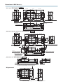
Dimensions of WRV*28 mm [in.]
Stroke
63 [2.480]
56 [2.205]
11.7 [0.461]
70 [2.756]
44 [1.732]
4-M6×1 Depth9 [0.354]
113 [4.449]+Stroke
35 [1.378]
37 [1.457]
6.5 [0.256]
21.6
[0.850]
2-Rc1/8
Connection port (left chamber)
(with 1 plug)
4-M2×0.4 Depth5 [0.197]
For mounting sensor rail
4-M2×0.4 Depth4 [0.157]
For mounting sensor magnet
80 [3.150]+Stroke
14 [0.551]
23
[0.906]
126 [4.961]+Stroke
s With shock absorber specification WRVM28CVA
46 [1.811]
35 [1.378]
19.5 [0.768]
14 [0.551]
23
[0.906]
Stroke
63 [2.480]
63 [2.480]
Stroke
64 [2.520]
45 [1.772]
56 [2.205]
11.7 [0.461]
70 [2.756]
72 [2.835]
2 [0.079]
4-φ7 [0.276]
6.5 φ11 [0.433] Counterbore, Depth6.5 [0.256]
[0.256]
2-Rc1/8
Connection port (right chamber)
(with 1 plug)
46 [1.811]
72 [2.835]
2 [0.079]
63 [2.480]
Stroke
64 [2.520]
19.5 [0.768]
46 [1.811]
35 [1.378]
45 [1.772]
s Basic type WRVP28CVK
4-φ7 [0.276]
6.5 [0.256] φ11 [0.433] Counterbore, Depth6.5 [0.256]
44 [1.732]
4-M6×1 Depth9 [0.354]
113 [4.449]+Stroke
46 [1.811]
6.5 [0.256]
48 [1.890]
8 [0.315]
M10×1 19 [0.748] MAX.
2-Rc1/8
Connection port (left chamber)
(with 1 plug)
4-M2×0.4 Depth5 [0.197]
For mounting sensor rail
4-M2×0.4 Depth4 [0.157]
For mounting sensor magnet
14 [0.551]
23
[0.906]
80 [3.150]+Stroke
126 [4.961]+Stroke
14 [0.551]
23
[0.906]
Stroke
8 [0.315]
110 [4.331]+Stroke
8
[0.315]
4 [0.157]
7 [0.276]
s With sensor rail WRVM28CVK
21.6
[0.850]
38.5
[1.516]
19 [0.748] MAX.
6.2 [0.244]
56 [2.205]
s M-type mount
76 [2.992]
88 [3.465]
84 [3.307]
±1
[±0.039]
The “With sensor rail” model is shipped with the sensor rail
and sensor magnet assembled on the piping port side.
4-M6×1
Depth9 [0.354]
1 [0.039]
9 [0.354]
38 [1.496]
¬¬¬¬¬¬¬¬¬¬¬¬¬¬¬¬¬¬¬¬¬¬¬¬¬¬¬¬Note: When using an M-type mount, be sure to remove the plate bum
2-Rc1/8
Connection port (right chamber)
(with 1 plug)
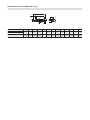
Dimensions of Shock Absorber
mm [in.]
A
B
C
K
G
φJ
N
Nut
F
E
L
(Width across flats)
D
(H)
(Stroke)
Q
mm [in.]
B
C
37
KSHJM8X5-22 (for WRVP22CVA) [1.457]
5
[0.197]
32
[1.260]
60
[2.362]
10
[0.394]
50
[1.969]
Model
A
KSHJM8X5-14 (for WRVP14CVA)
KSHJM10X10-28(forWRVP28CVA)
G
H
J
K
L
N
Q
1.2
2
[0.047] M8×7.5 [0.079]
10
[0.394]
11.5
[0.453]
2.5
[0.098]
3
[0.118]
7
[0.276]
1.3
[0.051]
1.5
[0.059]
2
[0.079]
12
[0.472]
13.9
[0.547]
3
[0.118]
5
[0.197]
8.5
[0.335]
1.3
[0.051]
1.5
[0.059]
D
E
M10×1
F
3
[0.118]
SENSOR SWITCHES
Solid State Type, Reed Switch Type
Symbol
Specifications
s
Solid State Type
Item
Model
XEZE1D / XEZE1L
XEZ31D / XEZ31L
2-lead wire
Wiring type
3-lead wire
Horizontal (D) - Bent 90° (L)
Lead wire direction
--
DC4.5~28V
Load voltage
DC10~28V
DC4.5~28V
Load current
4 ~ 20mA at 25oC [77oF], and 10mA at 60oC [140oF].
50mA MAX.
--
10mA MAX. (DC24V)
4.5V MAX.
0.5V MAX. (10V or less at 20mA)
Voltage
Consumption current
Internal voltage drop Note 1
Leakage current
50μA MAX. (DC24V)
1mA MAX. (DC24V, 25oC [77oF])
Response time
1ms MAX.
100M7 MIN. (At DC500V Megger, between case and lead wire terminal)
Insulation resistance
Dielectric strength
AC500V (50/60Hz) in 1 minute (Between case and lead wire terminal)
294.2m/s2 {30.0G} (Non-repeated shock)
Shock resistance Note 2
Vibration resistance Note 2
Total amplitude 1.5mm [0.06in.], 10 ~ 55Hz {88.3m/s2 (9.0G)}
Environmental protection
IEC IP67, JIS C0920 (Water-proof type)
Operating indicator
When ON: Red LED indicator lights up
Lead wire
PCCV 0.2SQ×2-lead (Brown and blue) ×2
Note3
PCCV0.15SQ×3-lead (Brown, blue, and black)×2
Ambient temperature
0o~ 60oC [32o~ 140oF]
Storage temperature range
-10 o~ 70oC [14o~ 158oF]
Mass
Note3
35g [1.23oz.] (For lead wire length B: 3000mm [118in.])
Notes: 1. The internal voltage drop depends on load current.
2. Measured by Automax test standard.
3. Lead wire length 2 : 3000m [118in.] ; M8 connector: 300mm.
s Reed Switch Type
Item
Model
XRZE1D / XRZE1L
XRZE0D / XRZE0L
2-lead wire
Wiring type
Horizontal (D) - Bent 90° (L)
Lead wire direction
Load voltage
DC5~28V
AC85~115V(r.m.s)
DC10~28V
Load current
40mA MAX.
20mA MAX.
5~40mA
Internal voltage drop Note 1
0mA
Response time
1ms MAX.
Dielectric strength
100M7 MIN. (At DC500V Megger, between case and lead wire terminal)
AC1500V (50/60Hz) in 1 minute (Between case and lead wire terminal)
294m/s2 {30.0G} (Non-repeated shock)
Shock resistance Note 2
Vibration resistance Note 2
Total amplitude 1.5mm [0.06in.], 10 ~ 55Hz {88.3m/s2 (9.0G)}, Resonance frequency 2750±250Hz
Environmental protection
Operating indicator
5~20mA
3.0V MAX.
0.1V MAX. (At 40mA load current)
Leakage current
Insulation resistance
AC85~115V(r.m.s)
IEC IP67, JIS C0920 (Water-proof type)
When ON: Red LED indicator lights up
None
Lead wire
PCCV0.2SQ×2-lead (Brown and blue)×2
Ambient temperature
0o~ 60oC [32o~ 140oF]
Storage temperature range
-10o~ 70oC [14o~ 158oF]
Contact protection
Mass
Notes: 1. The internal voltage drop depends on load current.
2. Measured by Automax test standard.
3. Lead wire length 2 : 3000mm [118in.] ; M8 connector: 300mm.
Note3
Required (See Contact Protection on p. )
35g [1.23oz.] (For lead wire length 3000mm [118in.])
Order Codes
• Sensor switch specification
XEZE1 D
-
Note: To order separately
M8
Lead wire termination
Blank : Without connector (length wire: 3000mm [118in.])
M8: With M8 connector (length wire: 300mm [11.8in.])
Lead wire orientation
D : Right output
L : Bent output (with angle 90°)
Sensor switch type
XEZE1D: 2-lead wire solid state type with indicator lamp DC10 ~28V
XEZE1L: 2-lead wire bent output solid state type with indicator lamp DC10 ~28V
XEZ31D: 3-lead wire solid state type with indicator lamp DC4.5 ~28V
XEZ31L: 3-lead wire bent outputsolid state type with indicator lamp DC4.5 ~28V
XRZE0D: 2-lead wire reed switch type without indicator lamp DC5 ~28V, AC85 ~115V
XRZE0L: 2-lead wire bent output reed switch type without indicator lamp DC5 ~28V, AC85 ~115V
XRZE1D: 2-lead wire reed switch type with indicator lamp DC10 ~28V, AC85 ~115V
XRZE1L: 2-lead wire bent output reed switch type with indicator lamp DC10 ~28V, AC85 ~115V
Internal Circuit Diagrams
• Solid state type
• 2-lead wire type (XEZE1D)
Brown(+)
• Without indicator lamp • With indicator lamp
Black
DC10~28V
Brown(+)
Blue
Blue(-)
DC4.5~28V
Blue(-)
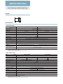
Dimensions of Sensor Switch
mm [in.]
Lead Wire
• Horizontal
Solid state type (XEZE1D, XEZ31D)
•
• Reed switch type
(XRZE0D, XRZE1D)
M2.5 Slotted head setscrew
M2.5 Slotted head setscrew
Indicator lamp Note
8 [0.315]
Maximum sensing location
15.5 [0.610]
60 [2.362]
2
(2 = 3000 [118])
4.6 [0.181]
4.6 [0.181]
φ2.6
[0.102]
XEZ
E1D
φ2.6
[0.102]
4 [0.157]
Indicator lamp
4 [0.157]
Brown
Load
Switch
Main circuit
Blue(-)
(6 [0.236])
(XRZE1D)
(XRZE0D)
Brown(+)
Load
Switch
Main circuit
• Reed switch type
• 3-lead wire type (XEZ31D)
8 [0.315]
(10 [0.394])
Maximum sensing location
22.5 [0.886]
60 [2.362]
2
(2 =3000 [118])
Note: Not available with XRZE0D
Moving Sensor Switch
Loosening the mounting screw allows the sensor switch to be
moved along the switch mounting groove on the barrel.
● Tighten the mounting screw with tightening torque of
0.1N・m? 0.2N・m {1kgf・cm? 2kgf・cm} [0.9in·lbf? 1.8in·lbf].
Sensor Switch Operating Range, Response Differential, and Maximum Sensing Location
● Operating range :2
The distance the piston travels in one direction, while the
switch is in the ON position.
● Response differential : C
The distance between the point where the piston turns the
switch ON and the point where the switch is turned OFF as
the piston travels in the opposite direction.
●Reed switch type
Model
Response
differential
WRVM22
WRVM28
7 ~ 8.6
[0.276 ~ 0.339]
7.5 ~ 8.6
[0.295 ~ 0.339]
6.8 ~ 8.5
[0.268 ~ 0.335]
1.2 [0.047]
or less
1.2 [0.047]
or less
1 [0.039]
or less
:C
Maximum sensing location
Magnet
mm [in.]
WRVM14
Operating range:R
Sensor switch
Maximum sensing
location※
2
Operating
C
range
Response
differential ON
OFF
10 [0.394]
OFF
Remark: The values in the above table are reference values.
※ : It is a value measured from the other end side of the lead wire.
Response
differential
mm [in.]
WRVM14
Operating range:R
:C
Maximum sensing
location※
2
Operating
range
●Solid state type
Model
ON
WRVM22
WRVM28
2.6 ~ 3.5
[0.102 ~ 0.138]
2.8 ~ 3.7
[0.110 ~ 0.146]
2.6 ~ 4.0
[0.102 ~ 0.157]
0.9 [0.035]
or less
1.1 [0.043]
or less
1.2 [0.047]
or less
C
Response
differential
6 [0.236]
Remark: The values in the above table are reference values.
※ : It is a value measured from the other end side of the lead wire.
Mounting the Sensor Rail and Sensor Magnet
The Flat Rodless cylinder has tapped holes on the cylinder’s
both sides for mounting the sensor rail and sensor magnet.
When securing the bolts, tighten to a suitable torque within the
allowed range limits.
Bolt
Maximum tightening torque N・m {kgf・cm} [in・lbf]
M2×0.4
0.2 {2} [1.8]
Sensor magnet
Bolt
Plate
Bolt
Magnet holder
Sensor rail
Bolt
Mounting Location of End of Stroke Detection Sensor Switch
When the sensor switch is mounted in the locations shown below, the magnet comes to the maximum sensing location of the sensor
switch at the end of the stroke.
A
B
C
E
E
D
G
H
A
B
F
●Reed switch-type (XRZE0D, XRZE1D)
mm [in.]
Model
A
B
C
D
WRVM14
41 [1.614]
15 [0.591]
13.5 [0.531]
16 [0.630]
WRVM22
52 [2.047]
18 [0.709]
21.5 [0.846]
24 [0.945]
WRVM28
63 [2.480]
23 [0.906]
27.5 [1.083]
30 [1.181]
E
22.5 [0.886]
F
G
7.2 [0.283]
1 [0.039]
6.2 [0.244]
H
2.5 [0.098]
7 [0.276]
4 [0.157]
●Solid state-type (XEZE1D, XEZ31D)
mm [in.]
Model
A
B
C
D
WRVM14
41 [1.614]
15 [0.591]
16.5 [0.650]
20 [0.787]
WRVM22
52 [2.047]
18 [0.709]
24.5 [0.965]
28 [1.102]
WRVM28
63 [2.480]
23 [0.906]
30.5 [1.201]
34 [1.339]
E
15.5 [0.610]
F
G
7.2 [0.283]
1 [0.039]
6.2 [0.244]
H
2.5 [0.098]
7 [0.276]
4 [0.157]
Contact Protection for Reed Switch Type Sensor Switches
In order to use the reed switch type sensor switches in a stable condition, take the following contact protection measures.
s
s When capacity serge is generated.
When connecting inductive load
(electromagnetic relay, etc.).
(When lead wire length exceeds 10m.)
Choke coil: 1~ 5mH
Inductive load
Sensor switch
Load
C surge suppressor
As close as possible
Serge absorption element
For DC… Diode, CR, etc.
For AC… CR, etc.
Diode: Forward current should be more than the circuit current.
Reverse voltage should withstand inverse voltage that is 10 times or more of the circuit voltage.
C: 0.01~ 0.1μF
R: 1~ 4k7
When Mounting the Cylinders with Sensor Switches in Close Proximity
When mounting Flat Rodless cylinders in close proximity, use them at the values shown in the table below, or larger.
A
●Reed switch type
B
D
C
E
mm [in.]
●Solid state type
mm [in.]
Model
A
B
C
D
E
Model
A
B
C
D
E
WRVM14
0
59.4 [2.339]
0
53.2 [2.094]
0
WRVM14
3 [0.118]
61.4 [2.417]
2 [0.079]
55.2 [2.173]
2 [0.079]
WRVM22
0
73.4 [2.890]
0
67.2 [2.646]
0
WRVM22
0
76.4 [3.008]
3 [0.118]
69.2 [2.724]
2 [0.079]
WRVM28
0
84.4 [3.323]
0
78.2 [3.079]
0
WRVM28
0
87.4 [3.441]
3 [0.118]
84.2 [3.315]
6 [0.236]
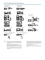
Points of Wiring Solid State Type Sensor Switches
s
s
s
2-lead wire type
s
Basic connection
Brown
Sensor
switch
Load
DC10 ~28V
Blue
s Connection with relays
(+)
(-)
3-lead wire type
Basic connection
Brown
Black
Blue
Sensor
switch
Load
DC4.5 ~28V
s Connection with relays
(+)
(-)
Brown
CR
Brown
Sensor
switch
Blue
AND (series) connection and OR (parallel)
connection
Relay
Sensor
switch
Relay
Sensor
switch
Black
Sensor
switch
Blue
AND (series) connection and OR (parallel)
connection
Sensor
switch
Relay
Sensor
switch
Relay
Sensor
switch
Relay
s Connection with TTL
Separate connection
(+)
Relay
Sensor
switch
CR
Relay contact
Vcc
Brown
Sensor
switch
Relay contact
Black
Blue
(-)
Load
Direct connection
Load
Relay contact
(+)
Brown
Relay contact
Sensor
switch
Load
Load
Black
Blue
(-)
s Connection with solenoid valve
(+)
(-)
s Connection with solenoid valve
(+)
s Connection to C-MOS
(-)
(+)
Brown
Brown
Brown
Sensor
switch
Black
Blue
Sensor
switch
Sensor
switch
Blue
Black
Blue
(-)
s Connection with programmable controller
Brown
Sensor
switch
Blue
Programmable
controller input
terminal
s Connection with programmable controller
Sensor
switch
Brown
Black
Blue
(+)
COM.
Cautions: 1. Connect wires according to the color of the lead wires. If the
connection is incorrect, it could cause damage to the sensor
switch due to the absence of a surge suppression protection.
2. Do not connect the 2-lead wire solid state type sensor switch
to TTL or C-MOS.
3. A surge suppression protection diode is recommended for the
inductive load of electromagnetic relays, etc.
4. Avoid series (AND) connection because the voltage of the
circuit will drop in proportion to the number of sensor switches.
5. When using parallel (OR) connection, the same sensor output
lines (e.g. the same black lead wires) can be connected
together, but the current leakage will increase by the number
of sensor switches. Therefore, be aware of load return
abnormalities.
Programmable
controller input
terminal
(+)
COM.
6. Because the sensor switches are a magnetically sensitive
type, avoid using them in locations subject to strong external
magnetic fields or bringing them too close to power lines or to
where other large electric currents are present. In addition, do
not use magnetic material for the mounting bracket, because it
will cause erratic operations.
7. Do not pull or bend the lead wires excessively.
8. Avoid using sensor switches in strong chemical or gas
environments.
9. Consult us for use in ambient atmospheres subject to water or
oil.