1
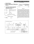
US008316110B1
(12) Umted States Patent
(10) Patent N0.:
Deshmukh et a].
(45) Date of Patent:
(54) SYSTEM AND METHOD FOR CLUSTERING
Nov. 20, 2012
i
,
(75)
US 8,316,110 B1
.................... 1.911641‘
,
0 an
et
.
.
STANDALONE SERVER APPLICATIONS AND
2003/0018927 A1*
1/2003 Gadir et al.
EXTENDING CLUSTER FUNCTIONALITY
2003/0126240 A1 *
2003/0177206 A1*
7/2003
9/2003
Inventors: Manav Deshmukh, Sunnyvale, CA
(Us). Kaushal Dalal Sunnyvale CA
2004/0267911 A1 * 12/2004 Alam .......................... .. 709/220
2005/0108593 A1* 5/2005 Purushothaman et a1. ..... .. 714/4
(US); Amol NeWaskar, Pune (IN);
“Windows NT Clustering Service” Gamache, R. Short, R. Massa, M.
’
_
Oct. 1998 IEEE Computer. vol. 31, Issue: 10. pp. 55-62.*
_
_
“A Highly Available Network File Server” Bhide, A. ElnoZahy, E.
(73) Asslgnee' symanliec Operatmg Corporatlon’
Morgan, S. 1991 in Proceedings oftheWinterUSENIX Conference.*
Mountaln VleW, CA (Us)
VMware P2V Assistant 1.0 User’s Manual, Version 1.0, Published:
Subject to any disclaimer, the term of this
patent is extended or adjusted under 35
U'S'C' 1546)) by 1135 days‘
Aug. 27, 2003 http://www.vmware.com/support/pubs/p2vipubs.
html.*
ggggnsMillerc
erver US ers,
J02 ?eerleilg
ICI‘OSO lgDelFloyingéolgéiesroso?
XC ange
erver,
1S e
Jul. 2001, Updated May 2002, Jul. 2002, Nov. 2002. Applies to
(*)
Notice:
(21)
Appl No ' 10/739 606
.
709/221
709/220
OTHER PUBLICATIONS
‘hillhgiizli/zt?zilggfl?zi’lggne (IN);
.
..... .. 714/4
Vosseler .... ..
Whitlow .
..
Exchange 2000 Server SP3.
,
* cited by examiner
(22) Filed:
(51)
Dec. 18, 2003
Primary Examiner * Kenny Lin
Assistant Examiner * Noel Beharry
Int. Cl.
G06F 15/1 77
(200601)
G06F 15/16
(2006.01)
(74) Attorney, Agent, or Firm * Campbell Stephenson LLP
(52)
us. Cl. ....................... .. 709/220; 709/202; 709/221
(58)
Field of Classi?cation Search .... .. 714/6; 709/201,
_ _
709/22W222
See apphcatlon ?le fOr Complete Search hlstol‘y_
References Clted
(56)
U.S. PATENT DOCUMENTS
6,134,673 A *
10/2000
applications and users. The virtual server is given the original
ChrabasZcZ ................... .. 714/13
6,151,688 A * 11/2000 Wipfelet al.
computer system’s network address. Cluster functionality
.... .. 714/4
.... .. 714/4
can further be extended to allow a virtual server to failover to
6/2001
8/2003
6,745,241 B1*
6/2004 French et al.
.. 709/221
7,010,717
3/2006
. . . . ..
7,058,858 B2*
Whitlow
.. ... .
server computer system name and can also be given the server
714/48
6,243,825 B1*
6,609,213 B1*
B2*
Gamache et al.
Nguyen et al.
(57)
ABSTRACT
Systems, methods, apparatus and software can implement
clusteriZing processes on existing standalone server applica
tion installations.A server computer system on which a server
application resides is renamed from its original name. Cluster
software is installed on the server computer system. A virtual
server is created to represent the server application to client
any other node available in a cluster.
714/4
31 Claims, 7 Drawing Sheets
6/2006 Wong et al. ................... .. 714/42
Gal VIRUJI lP mm;
315
330
Bl?d M001 1? Address to
Wmlal Sal/H Name
335
Muve SewerApphcatinn
340
Data 1» Shared Swage
Mme Hidden Objecu m
Sham! 5mm and
1mm 0mm nmmllar
345
350
355
Install Applimlion Sperm:
Cluslu Agent
Con?gure Appllcamn
5mm 0mm Agent
Fall Dpuamn
US. Patent
NOV. 20, 2012
US 8,316,110 B1
Sheet 1 0f 7
120
S erver A pp l'lca t‘mnE
ServerA l'cat‘o
pp| lnm
Local Storage
Local Storage
M
m
130/»
File System
Volume Management
150
SAN
180
160
170
Tape Library
JBOD
FIG. 1
(Prior Art)
Disk Array
\ 100
US. Patent
210%
Nov. 20, 2012
Dmnai"
Sheet 2 017
US 8,316,110 B1
DNS
Controller
110
29
LANIWAN
\ 120
Node 1 [Virtual Server
Node 2
r
N
f
\
Sewer Application
Sewer Application
\
E1
’
a
A
23] q
App.
Virtual
General
Specific
ZEN"
Service
\Agent(s)
232
k
260
24_1,
f
7
‘
Application
General
Speci?c
9e"2t39 Agent(s))
Private
Service
k Agent(s) 24 2
Agent(s) %
Network
[
Agent Framework E]
f
\
L
Agent Framework E]
f
Core Clustering Services
j
Core Clustering Services
235
r
245
\
FS
E
VM
a
’
05
\
F5
@J
\
2%
VM
05
a
E
2i},
m
SAN
f 150
Shared Storage
Server
Replicated Server Application
Registry Information ZQQ
Application
Database(s)
2E
FIG. 2
K 200
US. Patent
Nov. 20, 2012
Sheet 3 of7
US 8,316,110 B1
300
Prepare and Rename
Sewer
N 305
320" lnstall Cluster Software
V
325% Get Virtual IP Address
315
v
330m Bind Virtual IP Address to
Virtual Server Name
V
335% Move Server Application
Data to Shared Storage
V
Move Hidden Objects to
340%
Shared Storage and
Inform Domain Controller
V
345% Install Application Speci?c
Cluster Agent
V
350% Con?gure Application
Speci?c Cluster Agent
FIG. 3
v
Fail Operation
/
US. Patent
Nov. 20, 2012
1»
DNS
4 0
Controller
Sheet 4 017
US 8,316,110 B1
Lil
Ii]
L
4_20
“O
LAN/WAN
1
k
<
»
1
\120
430
440
450
' o
460
‘3:1 _ 23?“
Private
raj-=3
Network
Node1
-; 4 .
AVS1
"
L
Private
% g
NodeZ
Network
[III]
2: C :
f
1:33
c i:
Node3
AVS 1/2 of
‘1; 61,‘; i
'
AVSZ
150
SAN
Q
,
.
o
,
.1.‘
of
Shared Storage
480
AVS1
AVSZ
Database(s)
Database(s)
Replicated AVS1
Information %
Replicated AVSZ
Information @
w
‘\400
FIG. 4
US. Patent
Nov. 20, 2012
Sheet 5 of 7
500
510
/
Select Application Virtual
Server to be Configured
l
Associate Failover Nodes
520% with Application Virtual
Server
l
Take Corresponding
530%
Cluster Service Group
Offline
l
540%
Add Failover Nodes to
Service Group
l
550% Prioritize Failover Nodes
l
560%
Verify and Update
Information
l
570% Bring Service Group Online
580
FIG. 5
US 8,316,110 B1
US. Patent
Nov. 20, 2012
Sheet 6 of7
US 8,316,110 B1
600
Export Application
Information from Failed ~ 605
AVS
V
610% Stop Application Services
and Agent Services
l
515% Rename Current Session
V
620%
Select Failover Node
545M‘
Start Failover Node
V
Import Application
650% Information from Failed
AVS
V
655% Rename Current Session
on Failover Node
l
660m
Start Agent and
Application Services
665
FIG. 6
n
Ed
Fail Operation
US. Patent
Nov. 20, 2012
Sheet 7 of7
Application
Speci?c
General
Service
Agent(s)2:12-
L
US 8,316,110 B1
Agent(s)233
Agent Framework
Core Clustering Services
E
Memory E
x705
Processor
700 //
10
“I707
Keyboard & Mouse
Graphics & Display
E
1%
SCSI Interface
Hard Disk
E
E
Network Interface
CD-ROIVI
155
@
FIG. 7
US 8,316,110 B1
1
2
SYSTEM AND METHOD FOR CLUSTERING
STANDALONE SERVER APPLICATIONS AND
EXTENDING CLUSTER FUNCTIONALITY
nicate With hosts 130 and 140. In addition to netWork 120,
hosts 130 and 140 can communicate With each other over a
private netWork (not shoWn).
Other elements of computing system 100 include storage
FIELD OF THE INVENTION
area netWork (SAN) 150 and storage devices such as tape
library 160 (typically including one or more tape drives), a
group of disk drives 170 (i.e., “just a bunch of disks” or
The present invention relates to distributed computer sys
tems and, more particularly, to accommodating various appli
cations in clustered computer systems.
“.lBOD”), and intelligent storage array 180. As shoWn in FIG.
BACKGROUND OF THE INVENTION
coupling can be through single or multiple paths. SAN 150 is
conventionally a high-speed netWork that alloWs the estab
lishment of direct connections betWeen storage devices 160,
1, both hosts 130 and 140 are coupled to SAN 150. Such
Distributed computing systems are an increasingly impor
170, and 180 and hosts 130 and 140. SAN 150 can be imple
tant part of research, governmental, and enterprise computing
systems. Among the advantages of such computing systems
mented using a variety of different technologies including
SCSI, ?bre channel arbitrated loop (FCAL), ?bre channel
sWitched fabric, IP netWorks (e.g., iSCSI), In?niband, etc.
are their ability to handle a variety of different computing
scenarios including large computational problems, high vol
ume data processing situations, and high availability situa
tions. For applications that require the computer system to be
highly available, e.g., the ability to maintain the system While
SAN 150 can also include one or more SAN speci?c devices
such as SAN sWitches, SAN routers, SAN hubs, or some type
20
still providing services to system users, a cluster of computer
systems is a useful implementation of the distributed com
puting model. In the most general sense, a cluster is a distrib
uted computer system that Works together as a single entity to
of storage appliance. Thus, SAN 150 is shared betWeen the
hosts and alloWs for the sharing of storage devices betWeen
the hosts to provide greater availability and reliability of
storage. Although hosts 130 and 140 are shoWn connected to
storage devices 160, 170, and 180 through SAN 150, this need
25
not be the case. Shared resources can be directly connected to
cooperatively provide processing poWer and mass storage
some or all of the hosts in the computing system, and com
resources. With a cluster, the processing load of the computer
system is typically spread over more than one computer,
30
puting system 100 need not include a SAN. Other storage
schemes include the use of shared direct-attached storage
(DAS) over shared SCSI buses. Alternatively, hosts 130 and
140 can be connected to multiple SANs.
Hosts 130 and 140 can be designed to operate completely
independently of each other as shoWn, or may interoperate to
thereby eliminating single points of failure. Consequently,
programs executing on the cluster can continue to function
despite a problem With one computer in the cluster. In another
example, one or more computers of the cluster can be ready
for use in the event that another computer in the cluster fails.
While each computer in a cluster typically executes an inde
pendent instance of an operating system, additional cluster
ing softWare is executed on each computer in the cluster to
facilitate communication and desired cluster behavior.
FIG. 1 illustrates a simpli?ed example of a computing
system 100 that is not operating as a cluster. The members of
the computing system 100 include host 130 and host 140. As
members of computing system 100, hosts 130 and 140, are
typically individual computer systems having some or all of
the softWare and hardWare components illustrated. For
form some manner of cluster. As members of a cluster, servers
or
hosts are often referred to as “nodes.” Thus, a node in a
35
computer cluster is typically an individual computer system
having some or all of the softWare and hardWare components
illustrated and as is Well knoWn in the art.
In order to operate servers such as servers 130 and 140 as a
40
system, ?le system, volume management, server-to-server
communication) and any server applications operating on the
servers must be designed and/or con?gured to operate in a
cluster. Installing such systems typically occurs from the
example, hosts 130 and 140 operate as servers and as such
include Well knoWn hardWare and softWare components such
as: ?le system softWare, storage virtualiZation softWare (vol
ume management software), an operating system, various
drivers for the server’s hardWare, and platform hardWare such
as various interface devices. As servers, hosts 130 and 140
also include server applications (132 and 142) such as com
45
softWare is installed. In many cases, cluster aWare and/or
compatible server application softWare is speci?cally
50
cluster environments. For example, Microsoft Exchange
55
designed to support cluster operation only in conjunction
With clustering services provided by the Microsoft WindoWs
2000 Server operating system.
60
HoWever, there are many instances Where it is desirable to
transform an existing standalone server application installa
tion (such as those illustrated in FIG. 1) into a clustered
installation. The primary advantage to such a transformation
is that it obviates the need to undergo the laborious process of
storage (134 and 144) for server application con?guration
information, softWare components, operational information,
saving application data and con?guration information, unin
stalling the server application, upgrading/reinstalling/activat
ing clustering system softWare, reinstalling the server appli
In support of various applications and operations, hosts
130 and 140 can exchange data over, for example, netWork
120, typically a local area netWork (LAN), e. g., an enterprise
Wide intranet, or a Wide area netWork (WAN) such as the
Internet. Additionally, netWork 120 provides a communica
tion path for various client computer systems 110 to commu
designed to operate only in particular (typically proprietary)
2000 Server (a common e-mail server application) is
(DBMS), media servers, enterprise application servers, and
and data. FIG. 7 (described beloW) illustrates some of the
features common to such computer systems, and those having
ordinary skill in the art Will understand the Wide variation in
hardWare and softWare components of such systems.
ground up, i.e., ?rst basic system softWare is installed, then
system softWare needed to support clustering operations, and
?nally cluster aWare and/or compatible server application
munication and collaboration servers (e.g., e-mail servers),
Web servers, ?le servers, database management systems
the like. When operating on a server computer system, such
server applications typically utiliZe some amount of local
cluster, both the underlying system softWare (e.g., operating
cation, and recon?guring the server application. Moreover, it
65
is desirable to be able to implement such server applications
in clustering environments for Which they Were not necessar
ily designed and to extend to these server applications clus
US 8,316,110 B1
3
4
tering functionality which might not otherwise be available in
the clustering systems with which they have been designed to
the operations disclosed herein may be implemented in a
number of ways, and such changes and modi?cations may be
made without departing from this invention and its broader
operate.
aspects. Other aspects, inventive features, and advantages of
the present invention, as de?ned solely by the claims, will
become apparent in the non-limiting detailed description set
SUMMARY OF THE INVENTION
It has been discovered that systems, methods, apparatus
forth below.
and software can implement clusteriZing processes on exist
ing standalone server application installations. A server com
puter system on which a server application resides is renamed
from its original name. Cluster software is installed on the
server computer system. A virtual server is created to repre
sent the server application to client applications and users.
The virtual server is given the original server computer sys
BRIEF DESCRIPTION OF THE DRAWINGS
A more complete understanding of the present invention
and advantages thereof may be acquired by referring to the
following description and the accompanying drawings, in
tem name and can also be given the server computer system’ s
which like reference numbers indicate like features.
FIG. 1 is a simpli?ed block diagram of a computing sys
network address. Cluster functionality can further be
tem.
extended to allow a virtual server to failover to any other node
available in a cluster.
Accordingly, one aspect of the present invention provides a
method. A server computer system is provided having a ?rst
FIG. 2 is a simpli?ed block diagram of a clustered com
20
name, wherein the server computer system includes a server
invention.
FIG. 4 is a simpli?ed block diagram of a clustered com
application installed on the server computer system. The ?rst
name of the server computer system is changed to a second
name. Cluster software is installed on the server computer
system. The cluster software is con?gured to allow the server
computer system to operate as a node of a computer system
cluster. A virtual server associated with the server application
puting system utiliZing some of the systems and methods of
the present invention.
FIG. 3 is a ?ow chart illustrating techniques of the present
25
puting system utiliZing some of the systems and methods of
the present invention.
FIG. 5 is a ?ow chart illustrating techniques of the present
invention.
FIG. 6 is a ?ow chart illustrating techniques of the present
invention.
FIG. 7 is a block diagram of a computer system for imple
is created. The ?rst name is assigned as a virtual server name.
In another aspect of the present invention, a system
includes a memory, a processor coupled to the memory, and a 30
menting the techniques of the present invention.
local storage device coupled to the processor. A server appli
cation is stored on the local storage device. The computer
DETAILED DESCRIPTION
system also includes clusteriZing software con?gured to:
The following sets forth a detailed description of at least
change the ?rst name of the computer system to a second
name; create a virtual server associated with the server appli 35 the best contemplated mode for carrying out the one or more
devices and/or processes described herein. The description is
cation; and assign the ?rst name as a virtual server name. At
intended to be illustrative and should not be taken to be
least a portion of at least one of the server application and the
clusteriZing software is encoded as instructions stored in the
memory and executable on the processor.
limiting.
FIG. 2 illustrates a simpli?ed block diagram of a clustered
on a processor. The computer readable medium is at least one
computing system 200 utiliZing some of the systems and
methods of the present invention. In the example of FIG. 2,
clustered computing system 200 includes two cluster nodes
of an electronic storage medium, a magnetic storage medium,
an optical storage medium, and a communications medium
270, which can be one or more of the above described storage
In another aspect of the present invention, a computer
readable medium includes program instructions executable
conveying signals encoding the instructions. The program
40
230 and 240. The cluster nodes have access to shared storage
?rst name of a server computer system to a second name,
devices and canbe interfaced with the nodes through a variety
of techniques including the use of SAN 150. Each cluster
node includes typical computer system software such as a
wherein the server computer system includes a server appli
cation installed on the server computer system; creating a
virtual server associated with the server application; and
247), and a ?le system (236 and 246). Because servers 230
and 240 are operating as cluster nodes, this system software
45
instructions are operable to implement each of: changing a
operating system (238 and 248), a volume manager (237 and
50
can include functionality speci?cally for clustered operation.
assigning the ?rst name as a virtual server name.
Yet another aspect of the present invention provides an
In addition to the basic system software, there is software to
apparatus including: a means for changing a ?rst name of a
provide core clustering services (235 and 245). One example
of such software is the software provided in the VERITAS
server computer system to a second name, wherein the server
computer system includes a server application installed on 55 Cluster ServerTM (VCS) products from VERITAS Software
Corporation. Other cluster service software environments
the server computer system; a means for installing cluster
will be well known to those having ordinary skill in the art.
software on the server computer system, wherein the cluster
Core clustering services 235 and 245 typically provide
software is con?gured to allow the server computer system to
both the processes that operate on a particularnode to perform
operate as a node of a computer system cluster; a means for
creating a virtual server associated with the server applica 60 clustering functions and communications services so that
nodes can communicate and thereby operate in the desired
tion; and a means for assigning the ?rst name as a virtual
cluster con?guration. Cluster communications services
server name.
ensure that each node is continuously aware of the status of
each other node’s services and resources. They also enable a
The foregoing is a summary and thus contains, by neces
sity, simpli?cations, generaliZations and omissions of detail;
consequently, those skilled in the art will appreciate that the
summary is illustrative only and is not intended to be in any
way limiting. As will also be apparent to one of skill in the art,
65
node to recogniZe which other computer systems are active
members of a cluster, which are joining or leaving a cluster,
and which have failed.
US 8,316,110 B1
6
5
ply passes the online command to the DBMS agent, Which, in
turn, knoWs to issue the appropriate startup command. Agents
In the example of a VCS cluster implementation, core
clustering services (235 and 245) Would include a primary
process or high availability daemon (HAD) running on each
are also used to monitor resources for failure, to try to restart
node of the cluster. This process receives information from
various other softWare entities, e.g., kernel processes, user
applications such as command-line interface (CLI) and
a failed resource prior to declaring it faulted, and to inform the
core clustering services When a resource has failed.
In addition to the above described clustering softWare ele
graphical user interface (GUI) tools, drivers, utilities, and
agents (232, 233, 242, and 243), regarding resources on the
ments, core clustering services 235 and 245 can support or
local system and forWards the information to each member of
the cluster. The HAD also receives information from other
cluster members, Which it uses to update a local description of
the entire cluster. Communication betWeen the primary clus
Zational concepts for use in maintaining a cluster. One such
example is a service group. A service group is a collection of
implement a variety of features, data structures, and organi
resources Working together to provide application services to
clients. It typically includes multiple resources, hardWare and
softWare based, Working together to produce a single service.
ter processes on different cluster nodes occurs through kernel
level processes knoWn as the group membership services/
For example, a database service group may include a logical
atomic broadcast protocol (GAB) and the loW latency trans
netWork (IP) address, the DBMS softWare, underlying ?le
systems, logical volumes, and a set of physical disks managed
port (LLT).
GAB is a mechanism for monitoring cluster memberships,
tracking cluster state, and distributing the information to clus
ter systems. For example, cluster membership can be de?ned
as all systems con?gured With the same cluster ID and inter
by a volume manager. If a service group migrates to another
node for recovery purposes, all of the service group’s
resources migrate together to recreate the group on another
20
node, Without affecting other service groups. A single node
connected via a private netWork 260. As shoWn, private net
Work 260 is only accessible by cluster nodes, i.e., servers 230
may host several service groups, each providing a discrete
and 240. To support the high availability of cluster 200, pri
typically monitored and managed independently. Indepen
vate netWork 260 typically includes redundancy such as tWo
netWork paths instead of one. Private netWork 260 is used by
the nodes for cluster service message passing including, for
example, the exchange of so-called “heart-beat” signals indi
cating that each node is currently available to the cluster and
functioning properly. Similar functions can be implemented
using a public netWork. During standard operation, all sys
tems con?gured as part of the cluster during system installa
tion are actively participating in cluster communications.
Cluster membership enables each node to dynamically track
the entire cluster topology. GAB also provides state informa
tion about the resources of one node to all other cluster nodes.
Atomic broadcast ensures all systems Within the cluster are
service to netWorked clients. In that case, service groups are
dent management enables a service group to be recovered
25
30
used. For example, in some implementations, some or all of
35
immediately noti?ed of changes in resource status, cluster
membership, and con?guration.
LLT is the mechanism that provides actual communica
tions betWeen systems in a cluster. Speci?cally, it provides
automatically or idled manually (for administrative or main
tenance reasons) Without affecting other service groups run
ning on the node. Thus, a virtual server is typically main
tained in this type of clustering environment as part of one
service group.
As noted above, the clustering architecture described
herein is merely one example of the type of clustering archi
tecture With Which the present systems and methods can be
40
fast, kernel-to-kernel communications, provides the afore
mentioned heartbeat signals, and monitors private netWork
the agent functionality may be integrated With the core clus
tering services. In still other examples, clustering services are
part of a computer system’s operating system. Other varia
tions are Well knoWn to those having ordinary skill in the art.
Since the server application or applications that are desired
to be used in a clustered environment may be designed for
different clustering systems and may not be designed to be
converted from a regular server implementation to a clustered
implementation, care must be taken in implementing systems
and techniques to migrate such server applications to clusters
connections. LLT provides a replacement for other types of
and to extend to the server application cluster features not
communication protocols, e.g., IP, and is speci?cally
designed to ensure that events such as state changes are 45 originally intended by the server application’ s developer. The
re?ected among cluster nodes in a timely manner.
starting point for such implementations is an understanding
The various agents (e.g., application speci?c agents (232
of hoW the server application Was originally intended by its
developer to be presented in a cluster environment.
Many server applications are made available to cluster
and 242) and general service agents (233 and 243) of the core
clustering services 235 and 245 are programs designed to
control resources of a particular resource type. In general, a
resource is any hardWare or softWare entity, e.g., netWork
50
users or client applications as application virtual servers. One
example of such a server application is the aforementioned
server (231 and 241) such as a DBMS or an e-mail server.
Exchange 2000 Server from Microsoft Corporation. Note that
in many of the examples described beloW, reference Will be
made to features and characteristics of Exchange 2000 Server
and its implementation in a clustered environment. Exchange
2000 Server is merely one example of the type of server
application for Which the presently disclosed systems and
Agents can control resources according to information hard
methods can be used.
interface cards, IP addresses, applications, etc., that can be
brought online, taken of?ine of monitored by the clustering
services. For example, one agent can be in charge of moni
toring all IP resources on a node. In another example, the
55
agent is speci?c to a particular application running on the
coded into the agent itself, or by running scripts. Thus, agents
act as the intermediary (via agent frameWork 234 and 244)
In general, a virtual server is a highly scalable and highly
60 available server built on a cluster of “real” servers. The archi
betWeen resources and the core clustering services, and pro
tecture of the cluster is transparent to end users or client
vide ?exibility for implementing clusters using a variety of
different resources. An agent typically recogniZes the require
applications Which see only a single virtual server. Node 230
of the example cluster system 200 in FIG. 2 is also shoWn as
being a virtual server. In this example, softWare providing
certain virtual server functionality, e.g., functionality other
ments of its corresponding resource and communicates them
to the core clustering services. For example, to bring a DBMS
65
resource online, core cluster services 235 does not need to
than the server application itself, is provided Within the afore
understand the language or commands of the DBMS; it sim
mentioned agent frameWork as virtual server agent 239. In
US 8,316,110 B1
7
8
this manner, the virtual server can be controlled and treated in
much the same way as any other agent. In other embodiments,
clusteriZed) as the virtual server name. Consequently, the
virtual server functionality can be provided outside the cluster
agent framework. Although not shown, a virtual server agent
may also exist in node 240. For example, the agent can be
installed and ready to assume duties upon failover. Other
network entities such as domain controller 210 and domain
name indicating in some manner that it will be part of a
server is also renamed in 305, where it is typically given a
cluster. Additionally, if the server’s current IP address is
desired to be used as the IP address of the virtual server, i.e.,
a virtual IP address, or if it is otherwise desired to change the
server’s IP address, that operation can also be preformed at
this time.
name server 220, are typically aware of the virtual servers. To
users and clients, connecting to an application or service
The server is then examined to determine whether it can in
running as a clustered virtual server appears to be the same
process as connecting to a single, physical server. The user or
fact be made part of a cluster. This examination typically
includes: examining the server computer system for requisite
hardware (e.g., redundant host bus adapters, network inter
face cards for a private network, adequate storage, etc .), deter
mining if the existing system software is compatible with the
clustering software, and the like. If it is determined that the
client application typically does not know which node of a
cluster is actually hosting the virtual server. The real servers
may be interconnected by high-speed LAN or by geographi
cally dispersed WAN, and may implement any of a variety of
cluster con?gurations such as failover con?gurations or par
allel service con?gurations. Scalability of the virtual server
can be achieved by transparently adding or removing a node
in the cluster. In some implementations, multiple virtual serv
ers (particularly where each virtual server represents a differ
20
server computer system cannot be used in a cluster, the opera
tion fails 315 (typically with some error indication) and ter
minates at 355. If instead it is determined that the server
computer system can be used in a cluster, then operation
transitions to 320 where the cluster software is installed. In
ent application rather than multiple virtual servers running
general, the process of installing requisite cluster software
the same application) can exist on a single node.
assistance of an appropriate agent) manage the virtual server
such as, for example, core clustering services 235 and general
service agents 233, will vary greatly depending on the par
ticular clustering system used and is thus beyond the scope of
as another resource or resource group, with each virtual 25
the present application.
In a typical implementation, clustering services (with the
server having a virtual IP address and a virtual network name
As noted in connection with FIG. 2, the core clustering
(virtual server name) that is mapped to the virtual IP address.
services of a cluster node may use an application speci?c
Application client connections to a virtual server are made by
agent to manage the server application as a cluster resource.
a client session that knows only the virtual IP address that is
published as the address of the virtual server. Thus, the client
view is simply a view of individual network names and IP
addresses. In the event of an application or server failure,
30
Moreover, since the server application will make use of cer
clustering services move the entire virtual server resource to
another node in the cluster. When such a failure occurs, a
client will detect a failure in its session with the application
tain cluster resources, e.g., shared storage, some or all of
those resources may have to be made available before certain
35
operations can proceed. For example, if the server application
will need to use the shared storage to store information spe
ci?c to the server application, the shared storage may need to
and attempt to reconnect in exactly the same manner as the
original connection. It will be able to do this successfully,
because the clustering services map the published virtual IP
address of the virtual server to another node in the cluster. The
client session can reestablish the connection to the applica
Consequently, some of the operations discussed below may
be performed either by an application speci?c agent, or as part
of the process of installing and/or con?guring such an agent.
40
be made available, e.g., mounting volumes orpartitions on the
shared storage.
Once the server computer system has been made ready for
tion without needing to know that the application is now
cluster operation generally, the server application is con?g
physically hosted on a different node in the cluster.
ured for cluster operation. As noted above, the server appli
cation may not be speci?cally designed for operation in the
chosen cluster environment. Moreover, the server application
may best operate with other entities in the environment, e. g.,
users, client applications, domain controllers, domain name
servers, etc., under the identity of the server application’s
initial installation. Consequently, the process of con?guring
the server application for cluster operation will involve estab
To support the ability to failover a virtual server, important
server application information needs to be accessible to other
nodes of the cluster. In the example of FIG. 2, this is accom
45
plished by locating server application information such as
database(s) 280 and application registry information 290 on
shared storage 270. In some cases, certain information can
also be passed to other nodes or to the shared storage at the
time failure of the virtual server or its corresponding node is
detected.
While such virtual servers are often con?gured contempo
raneously with the installation of a server application, FIG. 3
illustrates a process where an existing standalone installation
50
lishing a virtual server based on the original identity of the
of a server application can be converted for use in a cluster. 55
server on which the server application resided. In step 325, a
virtual IP address is obtained for the virtual server. As noted
above, this can be the original IP address of the server com
puter system, or it can be a new (unique) virtual IP address.
This operation can also include other communications related
steps, such as selection of network adapters to be used, subnet
mask determination, etc.
Operation of the process to “clusteriZe” an existing installa
tion of a server application (and the server on which the server
application resides) begins at 300. At this point, there are
typically no clustering services on the server, or clustering
services are not activated. In step 305, the server and the
The process transitions to 330 where the virtual IP address
and the virtual server name, i.e., the original name of the
60
server application are prepared for the clusteriZing process.
This preparation typically includes shutting down server
application services, disabling automatic startup of some or
all server application services, backing up information stored
on the server, and the like. Since operation of the server
application will utiliZe a corresponding virtual server, this
process utiliZes the server’s current name (before it has been
server, are bound together and provided to appropriate cluster
system entities such as the node itself, domain controllers,
and domain name servers. Since one goal of a clustered
implementation of a server application is to allow that server
65
application to failover to another node in the cluster, the
clusteriZing process also ensures that relevant data and
objects are accessible to nodes that might assume operation of
the server application. The most obvious example of such
US 8,316,110 B1
9
10
information is the data regularly used by the server applica
supports server applications generally, speci?c types of
tion. Where the server application is the aforementioned
server applications, and/or speci?c server applications. The
process terminates at 355. Either immediately before 355, as
part of 355 or immediately after 355, the virtual server is
made part of a cluster service group. Similar steps may need
to be repeated for the con?guration of other nodes. In still
other examples, other nodes can be con?gured in a more
Exchange 2000 Server, information such as transaction log
?les, the public store ?les, and mailbox store ?les must be
made accessible to all nodes that Will be con?gured to operate
the corresponding virtual server. Consequently, server appli
cation data is moved to shared storage 335. The data move
ment process can involve other information, either additional
information that needs to be moved, or information that
should be consulted as part of the movement process. For
10
example, metadata stored in the domain controller may need
to be examined. Since the existing data Was generated by the
server name and virtual IP address Will be used to install
and/or con?gure the server application on other nodes. Once
complete, the server application can be restarted operating as
a virtual server that is ready for failover to other nodes as
server application before the clusteriZing process began, i.e.,
When the server application operated as a standalone server,
the data to be moved typically resides on local storage. The
process of moving this data may be as simple as executing
operating system level ?le copy commands. In some embodi
ments, utilities speci?c to the server application exist to
ensure that movement of such ?les is performed in a Way that
does not diminish their usability.
conventional manner, i.e., install and con?gure cluster soft
Ware ?rst, and then install and con?gure the appropriate
server application and agents. In general, the same virtual
necessary. Thus, by using the initial identi?cation of the
server as the virtual server identi?cation and relocating data
as necessary, an existing standalone server application can be
brought into a clustered environment.
Just as it is useful to extend clustering functionality to
20
applications that are already installed, thereby avoiding most
In addition to information such as the databases used in
conjunction With the server application, other relevant server
of the disadvantages of having to reinstall the application in a
clustered environment, it is further useful to extend the cluster
application information may need to be replicated onto
shared storage. For example, in the Microsoft WindoWs 2000
environment, a database called the registry is used to store
features supported by applications. Many server applications
support a limited set of cluster operations When used in the
25
clustering system for Which they are designed. For example,
settings, options, and information about the hardWare, soft
Ware, users, and preferences of the computer system. Registry
Microsoft Exchange 2000 Server is designed for use With
information corresponding to a server application can include
2000 Advanced Server and Datacenter Server products. HoW
vital information (e.g., checksum, security, application ser
vice information, etc.) needed for the operation of the virtual
clustering functionality provided by the Microsoft WindoWs
ever, When used as intended there are signi?cant limitations to
30
server on Whatever node it operates. Consequently, step 335
and/ or step 340 (described beloW) may include operations to
duplicate such information and make it available to failover
nodes.
Certain hidden objects can also be relocated to shared
35
storage (340). For example, a typical domain controller
implementation in the WindoWs 2000 environment utiliZes
the Active Directory service. In that context, Active Directory
uses objects, Which are the entities that make up a netWork.
Such an object is a distinct, named set of attributes that rep
the cluster operation of Exchange 2000 Server. In the case of
WindoWs 2000 Advanced Server, only a tWo node cluster is
supported for use With Exchange 2000 Server and those con
?gurations are limited to active/passive (Where a primary
node operates the virtual server and a secondary dedicated
node is used only When failover occurs on the primary node)
and active/active (Where both nodes are active and failover
requires the surviving node to take on processing operations
for both nodes). In the case of Microsoft WindoWs 2000 and
Datacenter Server, the cluster is limited to four nodes With
40 severe restrictions on Which nodes can be “active” Which can
resents something concrete, such as a user, a printer, or an
be “passive”.
application. When an Active Directory object is created,
Active Directory generates values for some of the object’s
FIG. 4 illustrates a cluster con?guration that illustrates the
extension of neW cluster con?gurations to server applications
such as Exchange 2000 Server. In many Ways, cluster system
400 is similar to the cluster illustrated in FIG. 2. Cluster
attributes, While others are provided by the user or application
that created the object. Thus, the server application that is the
subject of the clusteriZing operation typically has one or more
associated objects. Again, to support the ability of the virtual
server to operate on any designated node of the cluster, certain
objects should be duplicated and or moved to a location Where
they can be used by different nodes. In some cases, such an
45
system 400 has several nodes (430, 440, and 450) intercon
nected With private netWork 460, as Well as coupled to LAN/
WAN 120 and SAN 150. LAN/ WAN 120 alloWs various
client computer systems 110 and other entities, e.g., domain
50
operation also necessitates informing the domain controller.
Step 340 may also include moving data for Which there is no
existing specialiZed utility, but for Which care must be taken
none the less. In the example Where the server application is
Exchange 2000 Server, such data might include the message
55
transfer agent data. Still other examples Will be Well knoWn to
those having skill in the art.
Next, the application speci?c agent itself is installed (345)
ured as a failover node for either node 1 430 or node 3 450.
Thus node 2 440 can host either AVS1 or AVS2. Shared
Although many of the details of application agent installation
and con?guration are beyond the scope of this application,
storage 470 includes data for both application virtual servers,
e.g., databases(s) 470 and 480 and information (e.g., registry
information, domain controller objects, etc.) 485 and 495.
several speci?c details are discussed beloW in relation to
step. Similarly, agent con?guration may be replaced by con
?gurations operations targeting clustering functionality that
con?gured to operate as an instance of an application virtual
server (AVS1) for a particular server application. In this
example, node 3 450 is con?gured as a second instance of an
application virtual server (AVS2), and node 2 440 is con?g
on the server computer system and con?gured (350).
FIGS. 5 and 6. Moreover, some clustering system implemen
tations may not utiliZe agents (as described above), and so in
those environments there may be no explicit agent installation
controller 410 and domain name server 420 to communicate
With the cluster nodes, While SAN 150 (or some other suitable
interface as described above) alloWs nodes 430, 440, and 450
to all use shared storage 470 in furtherance of their clustered
operation. Also as previously discussed, node 1 430 can be
65
This con?guration illustrates one example of an any-to-any
capability extended to a server application that otherWise
does not support such a feature. In general, the any-to-any
con?guration can support many application virtual servers in
US 8,316,110 B1
11
12
the cluster, Where eachAVS is con?gured in a separate cluster
cess is complete (580). At this point, cluster operation can
service group. Each service group can fail over to any node in
resume based on the neW service group con?guration and
the cluster, provided that no other AVS is online on that node.
In the example of cluster system 400, the virtual servers are
con?gured in tWo service groups such that nodes 1 and 2 host
the AVS1 service group, While nodes 2 and 3 host the AVS2
failover scheme.
FIG. 6 illustrates a virtual server failover process for a
cluster con?gured for any-to-any failover operation. The pro
service group. If node 1 (or node 3) fails, the service group
cess begins at 600 Where some softWare entity, typically a
server application speci?c cluster agent, has detected that one
containing the AVS resources is failed over to node 2. This of
course is a very simple example. In more a complex example,
each of the tWo service groups includes all three nodes so that
or more server application processes have failed and/or that
the virtual server is no longer available. Note that other
events, e.g., hardWare failure, poWer loss, etc., can cause
a failure on, for example, node one cause the virtual server to
be failed over to node 2 or node 3, depending on a pre
that effect the entire node and not just a virtual server, are
arranged priority of nodes and depending on Whether a virtual
server is already operating on each of the nodes. Variations
and extensions of this technique to greater numbers of nodes
can be understood by those having ordinary skill in the art. In
addition, since the techniques can be extended to server appli
cations not speci?cally designed for the extend cluster func
tionality, it may be desirable or necessary to con?gure the
server application for a particular type of “native” cluster
environment, i.e., a mode of cluster operation for Which it is
designed to operate. For example, if the server application is
failover. These types of failover conditions, i.e., conditions
typically handled by core clustering services and/or general
purpose agents. A description of such failover operations is
beyond the scope of the present application.
Once a virtual server failover condition has been detected
20
being provided by that node. In the simplest example, export
Exchange 2000 Server, it may be desirable or necessary, e. g.,
for ease of later con?guration, to initially con?gure the
and the failover process initiated, operation transitions to 605
Where certain server application information is exported from
the failed application virtual server. For example, the node
implementing the failed virtual server may include registry
information indicating that various application services are
25
ing such information merely assures that the information is
available to the possible failover nodes. In more complex
examples, the export operation informs certain processes or
instance of Exchange 2000 Server for one of an active/active
entities on the node With the failed virtual server that the node
and an active/passive implementation.
Will no longer be hosting the virtual server and/or providing
services associated With the virtual server. For example, the
export operation can explicitly remove service related infor
mation from a registry database. Next, any relevant applica
tion services and/or cluster agents are stopped (610). Since
many applications include multiple services or processes, a
failure of one or more of those, While being signi?cant
enough to prompt failover, may not immediately cause all
related process or services to fail. Consequently, it is desirable
FIG. 5 illustrates a process for con?guring such any-to-any
operation. In one embodiment, the process described in FIG.
5 (and FIG. 6 beloW) is performed by or in conjunction With
30
an application speci?c cluster agent. Thus, some or all of the
steps might be performed as agent con?guration steps, as
agent-related utility execution, or autonomously by an agent.
In other embodiments Where the clustering system does not
implement agents as described herein, such steps may be
35
replaced by con?guration operations targeting clustering
to terminate any remaining related processes or services in a
functionality that supports server applications generally, spe
stateful manner. Similarly, a virtual server may make use of
ci?c types of server applications, and/or speci?c server appli
cations.
one or more general service agents that should be shutdoWn
before the virtual server is transferred to a neW node.
servers begins at 500. The particular application virtual
Since another node in the cluster Will take over the virtual
server (and ultimately take the virtual server’s name and
server, e. g., a particular instance of an Exchange virtual
server, is selected (510). In general, there can be as many
virtual IP address), the current session name on the node on
Which the virtual server has failed is renamed as shoWn at 615.
Con?guration of a cluster operating one or more virtual
40
cluster having n nodes. Once the particularAVS to be con?g
The renaming process may give the current session name a
neW temporary name, perhaps indicative of the failure, or may
simply use the computer name for the node. For example, in
ured is selected, operation transitions to 520 Where one or
more failover nodes are associated With the particular virtual
the context of WindoWs registry entries, the ActiveComput
erName entry (HKEY_LOCAL_MACHINE\ SYSTEM\
different virtual server instances as there are nodes. HoWever,
typical implementations Will have n—1 virtual servers for a
45
CurrentControlSet\Control\ComputerName\Active
server. This process can include additional operations such as
verifying that each of the selected nodes is capable of hosting
50
are currently being used as possible hosts for the virtual
server.
Next the cluster service group corresponding to the par
ticular virtual server for Which failover nodes Where associ
55
ated in 520 is taken of?ine (530). This operation is typically
performed because updates to a service group should be per
formed and propagated to all relevant nodes before the
changes take effect. Once the service group is of?ine, the
ComputerName represents the current session name.
Next in 620, the node that is to host the virtual server, i.e.,
the failover node is selected. In some cases there Will be only
one possible choice. In others, there may be multiple possible
failover nodes and possibly a predetermined priority With
60
failover nodes are added to the service group as shoWn at 540.
Since more than one failover node may exist, the order in
Which failover nodes are selected, i.e., the failover priority,
can also be speci?ed 550. All of the requested con?guration
changes are then veri?ed and corresponding information
updated (560). Once this task is complete, the service group
can be brought back online (570) and the con?guration pro
ComputerName) before the failure is set to the name of the
virtual server. In performing step 615, that entry’s value is
changed, for example, to the current value of ComputerName
Which is typically the computer system’s name While Active
a virtual server. In a typical implementation, all available
nodes are displayed for selection as Well as those nodes that
65
Which failover nodes are used. As noted above, the available
node or nodes and any priority information are typically
determined during a con?guration process such as that illus
trated in FIG. 5. Once a failover node is selected, operation
transitions to 625 Where it is determined if the selected node
is available for use. In some cases the node may not be
available or suitable for use, e.g., a virtual server is already
being hosted by the selected failover node, some failure has
occurred on the failover node, etc. If the selected failover
US 8,316,110 B1
13
14
node is not available, a determination is made (635) Whether
there is another node that can be selected. If so, operation
Working together. Memory 720 is typically random access
memory (RAM), or some other dynamic storage device, and
is capable of storing instructions to be executed by the pro
cessor, e.g., softWare 232, 233, 234, and 235 and its compo
nents. Memory 720 is also used for storing temporary vari
ables or other intermediate information during the execution
of instructions by the processor 710.
returns to 620 Where the neW failover node is selected. If no
other node is available, the virtual server failover procedure
cannot be accomplished and the operation fails 640 (typically
With some error indication) and terminates at 665.
Once an available node has been selected, the failover node
is started (645). In some cases, the node Will already be
Those having ordinary skill in the art Will readily recogniZe
started, that is it is already operating as part of the cluster. Any
that the techniques and methods discussed beloW can be
information needed to operate as the virtual server is imported
650. In some cases, the information Will be accessible to the
implemented in softWare using a variety of computer lan
guages, including, for example, traditional computer lan
guages such as assembly language, Pascal, and C; object
oriented languages such as C++, C#, and Java; and scripting
failover node via shared storage. In other examples, the failed
node may pass the information directly to the failover node.
As noted above, a typical example of such information is
server application registry information. In such an example,
languages such as Perl and Tcl/Tk. Additionally, softWare 230
can be provided to the computer system via a variety of
computer readable media including electronic media (e.g.,
?ash memory), magnetic storage media (e. g., hard disk 758,
a ?oppy disk, etc.), optical storage media (e.g., CD-ROM
760), and communications media conveying signals encod
the importation process includes the process of making the
information available as part of the failover node’ s registry. In
step 655, the current session name (e.g., the aforementioned
ActiveComputerName) for the failover node is renamed to
have the virtual server name. This operation is performed so
that users and client applications of the virtual server can
redirect communication to the failover node in an ef?cient
20
interface 754).
Computer system 700 also includes devices such as key
board & mouse 750, SCSI interface 752, netWork interface
and Well established fashion. Any agents and/or server appli
cation services are started in 660 thereby rendering the virtual
server functional again on the failover node. The process
terminates at 665.
The How charts of FIGS. 3, 5, and 6 illustrate some of the
many operational examples of the clusteriZing and extended
cluster features disclosed in the present application. Those
having ordinary skill in the art Will readily recogniZe that
ing the instructions (e.g., via a netWork coupled to netWork
754, graphics & display 756, hard disk 758, and CD-ROM
25
760, all of Which are coupled to processor 710 by communi
cations bus 707. It Will be apparent to those having ordinary
skill in the art that computer system 700 can also include
numerous elements not shoWn in the ?gure, such as additional
storage devices, communications devices, input devices, and
30
certain steps or operations illustrated in FIGS. 3, 5, and 6 can
be eliminated or taken in an alternate order. Moreover, the
methods described in FIGS. 3, 5, and 6 and many of the
modules illustrated in FIG. 2 are typically implemented as
output devices, as illustrated by the ellipsis shoWn. An
example of such an additional computer system device is a
?bre channel interface.
Although the present invention has been described With
respect to a speci?c preferred embodiment thereof, various
one or more software programs for a computer system and are 35 changes and modi?cations may be suggested to one skilled in
executable on one or more processors. The computer readable
the art and it is intended that the present invention encompass
such changes and modi?cations fall Within the scope of the
medium can be any one of an electronic storage medium, a
appended claims.
encoded in a computer readable medium as instructions
What is claimed is:
magnetic storage medium, an optical storage medium, and a
communications medium conveying signals encoding the
40
1. A method comprising:
instructions. Separate instances of these programs can be
changing a ?rst name of a server computer system to a
executed on separate computer systems in keeping With the
multi-process methods described above. Thus, although cer
tain steps have been described as being performed by certain
second name, Wherein
the server computer system has no clustering services
devices, softWare programs, processes, or entities, this need
not be the case and a variety of alternative implementations
Will be understood by those having ordinary skill in the art.
Additionally, those having ordinary skill in the art Will
readily recogniZe that the techniques described above can be
utiliZed in a variety of different storage devices and comput
ing systems With variations in, for example, the number of
nodes, the type of operation of the computing system, e.g.,
installed When the changing is performed,
45
tem and a separate server application installed on the
server computer system, and
the server application is con?gured as a non-clustered
standalone installation;
50
cluster operation (failover, parallel, etc.), the number and type
installed,
nodes and shared data resources. The softWare can operate on 55
the cluster softWare provides communications services,
and 2, or may operation in storage appliances, sWitches, dis
tributed virtualiZation environments (e.g., Where certain vir
tualiZation tasks are performed by different devices), and the
60
700 for implementing the fencing techniques of the present
coupled together by communications bus 705. Processor 710
can be a single processor or a number of individual processors
the installing the cluster softWare does not require rein
stallation of the server application,
host computer systems such as those illustrated in FIGS. 1
invention. For example, computer system 700 can be an
embodiment of one of the previously described hosts. Com
puter system 700 includes a processor 710 and a memory 720
installing cluster softWare on the server computer system,
Wherein
the server application is already installed on the server
computer system When the cluster softWare is
of shared data resources, and the number of paths betWeen
like.
FIG. 7 illustrates a block diagram of a computer system
the server computer system includes an operating sys
the cluster softWare alloWs the server computer system
to operate as a node of a computer system cluster, and
the cluster softWare communicates information indicat
ing a state of at least one node in the computer system
cluster using an intra-cluster communication proto
col;
installing a plurality of agents on the server computer sys
65
tem, Wherein
the plurality of agents act as intermediaries betWeen
resources and core clustering services, Wherein
US 8,316,110 B1
15
16
the computer system comprises:
the resources comprise hardware resources and soft
a memory;
ware resources,
a ?rst agent of the plurality of agents is a general service
agent that controls the hardware resources, wherein
a processor coupled to the memory;
a local storage device coupled to the processor;
an operating system; and
the hardware resources are monitored by the cluster
software, and
a second agent of the plurality of agents is an application
speci?c agent associated with the server application,
wherein
the second agent provides the server application with
a separate server application stored on the local storage
device, wherein
the server application is initially con?gured as a non
10
any-to-any failover con?guration information, and
create a virtual server, wherein
the any-to-any failover con?guration information com
the virtual server comprises the server computer sys
prises failover priority information,
tem,
creating a virtual server, wherein
the virtual server comprises the server computer system;
assign the ?rst name as a virtual server name of the
virtual server,
enable the server computer system to operate as a node
assigning the ?rst name as a virtual server name of the
virtual server; and
establishing a connection to the virtual server in response
to receiving a request to establish a connection to the
server application.
of a computer system cluster,
establish a connection to the virtual server in response to
receiving a request to establish a connection to the
20
2. The method of claim 1 further comprising:
providing a virtual IP address corresponding to the virtual
services, wherein
25
method further comprising:
changing the server computer ?rst IP address to a server
computer second IP address, wherein the virtual IP
address corresponding to the virtual server is the server
computer ?rst IP address.
4. The method of claim 2 further comprising:
transmitting the virtual IP address and virtual server name
30
application, wherein
35
prising:
comprises failover priority information,
transferring at least a portion of the server application data
40
cluster shared storage device.
6. The method of claim 1 wherein the server application is
cluster software on the local storage device,
45
7. The method of claim 1 further comprising:
determining whether the server computer system can oper
50
8. The method of claim 1 further comprising:
installing a cluster agent on the server computer system,
wherein the cluster agent is con?gured to speci?cally
55
ware on the computer system, wherein the cluster soft
ware is operable to allow the computer system to operate
as a node of a computer system cluster.
12. The computer system of claim 10 wherein the cluster
software is further con?gured to receive a virtual IP address
60
corresponding to the virtual server.
13. The computer system of claim 12 further comprising:
a computer system ?rst IP address; wherein the cluster
nodes also hosts an instance of the virtual server.
10. A computer system having a ?rst name, wherein
the ?rst name is con?gured to be changed to a second
software is further con?gured to change the computer
system ?rst IP address to a computer system second IP
name,
the server computer system has no clustering services
installed when the ?rst name is changed to the second
name, and
at least a portion of at least one of the server application and
the cluster software is encoded as instructions stored in
the memory and executable on the processor.
11. The computer system of claim 10 further comprising:
installation software con?gured to install the cluster soft
associated with an instance of the virtual server hosted
on that node can fail over to any other node in the cluster,
and wherein at least one other node of the plurality of
the cluster software provides communications services,
the cluster software is con?gured to communicate infor
mation indicating the state of at least one node in the
cluster using an intra-cluster communication protocol,
and
agement system (DBMS), a media server application, and an
enterprise application server.
operate with the server application.
9. The method of claim 1 wherein:
the cluster comprises a plurality of nodes; and
each node is con?gured such that a cluster service group
the server application is already stored on the local storage
device when the cluster software is installed,
installation of the cluster software does not require rein
stallation of the server application,
installation of the cluster software comprises storing the
at least one of a communication server application, a collabo
ration server application, and e-mail server application, a web
ate as a cluster node.
the second agent provides the server application with
any-to-any failover con?guration information, and
the any-to-any failover con?guration information
system includes a storage device, and wherein the storage
device stores server application data, the method further com
server application, a ?le server application, a database man
a ?rst agent of the plurality of agents is a general
service agent that controls the hardware resource,
wherein
the hardware resource monitored by the cluster
software, and
server, and client computer system.
from the server computer system storage device to a
the resources comprise hardware resources and
software resources,
a second agent of the plurality of agents is an appli
cation speci?c agent associated with the server
to at least one of a domain controller, a domain name
5. The method of claim 1 wherein the server computer
server application,
communicate with a plurality of agents, wherein
the plurality of agents are con?gured to act as inter
mediaries between resources and core clustering
server.
3. The method of claim 2 wherein the server computer
system includes a server computer ?rst IP address, the
clustered standalone installation;
cluster software con?gured to:
65
address, and wherein the virtual IP address correspond
ing to the virtual server is the computer system ?rst IP
address.
US 8,316,110 B1
17
18
14. The computer system of claim 12 wherein the cluster
software is further con?gured to:
the cluster software is con?gured to allow the server com
puter system to operate as a node of a computer system
cluster, and
transmit the virtual IP address and virtual server name to at
least one of a domain controller, a domain name server,
the server application is already installed on the server
computer system when the program instructions are
executed.
and client computer system.
15. The computer system of claim 10 wherein the local
storage devices stores server application data, and wherein
the cluster software is further con?gured to:
transfer at least a portion of the server application data from
the computer system to a cluster shared storage device.
16. The computer system of claim 10 wherein the server
18. The non-transitory computer readable medium of claim
17 further comprising program instructions operable to
implement:
installing the cluster software on the server computer sys
tem, wherein the cluster software is con?gured to allow
application is at least one of a communication server appli
cation, a collaboration server application, and e-mail server
application, a web server application, a ?le server application,
a database management system (DBMS), a media server
computer system cluster.
19. The non-transitory computer readable medium of claim
17 further comprising program instructions operable to
application, and an enterprise application server.
implement:
the server computer system to operate as a node of a
17. A non-transitory computer readable medium compris
providing a virtual IP address corresponding to the virtual
ing program instructions executable on a processor, the com
puter readable medium being at least one of an electronic
server.
20
storage medium, a magnetic storage medium, and an optical
storage medium, wherein
19 wherein the server computer system includes a server
computer ?rst IP address, the computer readable medium
further comprising program instructions operable to imple
the program instructions are executable to
change a ?rst name of a server computer system to a
second name, wherein
the server computer system has no clustering services
installed when the ?rst name is changed to the
second name,
the server computer system includes an operating sys
ment:
25
changing the server computer ?rst IP address to a server
computer second IP address, wherein the virtual IP
address corresponding to the virtual server is the server
tem and a separate server application installed on 30
the server computer system, and
computer ?rst IP address.
21. The non-transitory computer readable medium of claim
20 further comprising program instructions operable to
implement:
install cluster software, wherein
installation of the cluster software does not require
reinstallation of the server application,
the cluster software is operable to
20. The non-transitory computer readable medium of claim
transmitting the virtual IP address and virtual server name
to at least one of a domain controller, a domain name
35
create a virtual server associated with the server appli
server, and client computer system.
22. The non-transitory computer readable medium of claim
17 wherein the server computer system includes a storage
cation, wherein
device, and wherein the storage devices stores server appli
the virtual server comprises the server computer sys
tem,
assign the ?rst name as a virtual server name of the 40
cation data, the computer readable medium further compris
ing program instructions operable to implement:
transferring at least a portion of the server application data
virtual server,
establish a connection to the virtual server in response to
from the server computer system storage device to a
reception of a request to establish a connection to the
server application, and
cluster shared storage device.
23. The non-transitory computer readable medium of claim
communicate with a plurality of agents, wherein
the plurality of agents are con?gured to act as inter
45
mediaries between resources and core clustering
services, wherein
the resources comprise hardware resources and
software resources,
(DBMS), a media server application, and an enterprise appli
50 cation server.
24. The non-transitory computer readable medium of claim
17 further comprising program instructions operable to
a ?rst agent of the plurality of agents is a general
service agent con?gured to control the hardware
implement:
resource, wherein
the hardware resource monitored by the cluster
software, and
determining whether the server computer system can oper
55
implement:
application, wherein
the second agent provides the server application with
installing a cluster agent on the server computer system,
60
26. An apparatus comprising:
the cluster software provides communications services,
indicative of the state of at least one node in the cluster
using an intra-cluster communication protocol,
wherein the cluster agent is con?gured to speci?cally
operate with the server application.
comprises failover priority information,
wherein
the communication services communicate information
ate as a cluster node.
25. The non-transitory computer readable medium of claim
17 further comprising program instructions operable to
a second agent of the plurality of agents is an appli
cation speci?c agent associated with the server
any-to-any failover con?guration information, and
the any-to-any failover con?guration information
17 wherein the server application is at least one of a commu
nication server application, a collaboration server applica
tion, and e-mail server application, a web server application,
a ?le server application, a database management system
a means for changing a ?rst name of a server computer
system to a second name, wherein
65
the server computer system has no clustering services
installed when the ?rst name is changed to the second
name,
US 8,316,110 B1
19
20
the cluster software is con?gured to communicate infor
mation indicating the state of at least one node in the
cluster using an intra-cluster communication proto
the server computer system includes an operating sys
tem and a separate server application installed on the
server computer system,and
col; and
the server application is con?gured as a non-clustered
a means for creating a virtual server associated with the
standalone installation;
server application, wherein
the virtual server comprises the server computer system;
a means for installing cluster software on the server com
puter system, wherein
a means for assigning the ?rst name as a virtual server
the server application is already installed on the server
name of the virtual server; and
computer system when the cluster software is
a means for establishing a connection to the virtual server
in response to reception of a request to establish a con
installed,
installation of the cluster software does not require rein
stallation of the server application,
the cluster software is con?gured to allow the server
nection to the server application.
27. The apparatus of claim 26 further comprising:
a means for providing a virtual IP address corresponding to
the virtual server.
computer system to operate as a node of a computer
28. The apparatus of claim 27 wherein the server computer
system includes a server computer ?rst IP address, the appa
system cluster,
the cluster software is con?gured to communicate with a
ratus further comprising:
plurality of agents, wherein
the plurality of agents are con?gured to act as inter
mediaries between resources and core clustering
20
services, wherein
the resources comprise hardware resources and
software resources,
a ?rst agent of the plurality of agents is a general
service agent con?gured to control the hardware
29. The apparatus of claim 27 further comprising:
a means for transmitting the virtual IP address and virtual
25
resource, wherein
the hardware resource is monitored by the cluster
software, and
a second agent of the plurality of agents is an appli
cation speci?c agent associated with the server
30
application, wherein
the cluster software provides communications services,
and
server name to at least one of a domain controller, a
domain name server, and client computer system.
30. The apparatus of claim 26 wherein the server computer
system includes a means for storing data, and wherein the
means for storing data stores server application data, the
apparatus further comprising:
a means for transferring at least a portion of the server
application data from the server computer system means
for storing data to a shared means for storing data.
the second agent provides the server application with
any-to-any failover con?guration information, and
the any-to-any failover con?guration information
comprises failover priority information,
a means for changing the server computer ?rst IP address to
a server computer second IP address, wherein the virtual
IP address corresponding to the virtual server is the
server computer ?rst IP address.
31. The apparatus of claim 26 further comprising:
35
a means for determining whether the server computer sys
tem can operate as a cluster node.
*
*
*
*
*