1
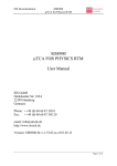
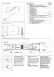
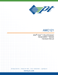
0ACKAGING3OLUTIONS .EWSTANDARDSFORHIGHSPEEDNETWORKS DVANCED4#!3YSTEM ! ASSEMBLEDWITH !DVANCED-##ARRIER AND-ODULES DVANCED-#-ODULES ! INSIDEA#ARRIER « 4#!3YSTEMASSEMBLED WITH!DVANCED4#! -ODULES DVANCED-# ! -ODULES « 4#!3UBRACK ASSEMBLEDWITH !DVANCED-#-ODULES .EW$EMANDS OMPETITIVE!DVANTAGESWITHANEW # %QUIPMENT'ENERATION )NCREASING DATA TRAFlC AND NEW COMMUNICATION 4 HE PRESENT SITUATION IN THE TELECOMMUNICATION SERVICES DEMAND mEXIBLE RELIABLE AND SCALABLE SECTOR SHOWS THAT OF ALL SYSTEMS ARE INFRASTRUCTURES PROPRIETARY-ANYTELECOMMUNICATIONCOMPANIES HOWEVER CANNOT OR DO NOT WANT TO DEVELOP OR 3INCE0)#-'HASTHEREFOREINVESTIGATEDWHAT OPERATE PROPRIETARY SYSTEMS ANY LONGER BUT ARE THE MARKET EXPECTS FROM A NEW FORWARDLOOKING DEMANDINGASTANDARDISEDINFRASTRUCTURE STANDARDFORTELECOMMUNICATIONAPPLICATIONS 7ITHTHENEW!DVANCED4#!EQUIPMENTGENERATION 4HERESULTING!DVANCED4#!STANDARDDEMANDSAN HARDWAREANDSOFTWARECOMPONENTSFROMDIFFERENT EFFECTIVECAPACITYFORDATATRANSFERSUPTO4BITS MANUFACTURERSCANBEUTILISEDANDCOMBINED4HIS ALONG WITH AVAILABILITY OF THE SYSTEM NEW TECHNOLOGY OFFERS A mEXIBLE COST EFFECTIVE MEANING THAT SUCH A SYSTEM IS ONLY ALLOWED TO MODULE WITH LOW DEVELOPMENT COSTS AND SHORT BE INOPERABLE FOR MAX MINUTES PER YEAR PRODUCTLAUNCHTIMES &URTHERMOREDIFFERENTPROTOCOLSSUCHAS%THERNET )NlNIBAND3TAR&ABRIC0#)%XPRESSAND2APID)/ FORFASTINTERFACESHAVETOBESUPPORTED !PPLICATIONS 4 HE !DVANCED4#! STANDARD WAS ORIGINALLY DEl NEDFORTHEAPPLICATIONSINTHETELECOMMUNICATION SECTOR4HEPLATFORMORIENTATEDCONCEPTISIDEALLY SUITEDFOR7IRELESS7IRELINE6OICEOVER)06IDEO ON $EMAND AND "ROADBAND PLATFORM SERVICES 3WITCHESROUTERSANDOTHERNETWORKAPPLICATIONS PROlT THROUGH THE EXTREMELY HIGH DATA TRANSFER RATESOFABOVE4BITS 4HROUGHFURTHERDEVELOPMENTOF!DCANCED-#AND «4#! ADDITIONAL AREAS OF APPLICATION HAVE BEEN CREATEDINTHEMIDANDLOWENDAREA ! DVANCED4#! OR SHORT !4#! STANDS FOR !DVANCED 4ELECOM #OMPUTER !RCHITECTURE !4#! IS THE THIRD MAIN GROUP OF STANDARDS ISSUED BY 0)#-' 0#) )NDUSTRIAL #OMPUTER -ANUFACTURERS 'ROUP FOLLOWINGTHEPASSIVE0#)"ACKPLANE AND#OMPACT0#)STANDARDS 4 OREADMOREPLEASETURNTO 0AGEn3YSTEMS 0AGEn#ABINETS 4 HE !DVANCED-# STANDARD IS AN IMPORTANT PART OF THE !DVANCED4#! PLATFORM !DVANCED-# MODULES CONTAIN ADDITIONAL BOARDS WHICH EXTEND THE FUNCTION OF A #ARRIER "OARD CONSIDERABLY 4OREADMORE PLEASETURNTO0AGE ICRO4#! IS A VERY MODULAR STANDARD WITH THE AIM TO ASSEMBLE !DVANCED-#MODULESDIRECTLYONTHE BACKPLANE WITHOUT THE REQUIREMENT FOR A #ARRIER "OARD IN COST CRITICAL APPLICATIONSINTHELOWENDAREA 4 OREADMORE PLEASETURNTO0AGE #OOLING#ONCEPTS & AST PROCESSORS CREATE HIGH PERFORMANCE LOSSES AND REQUIRE A CAREFULLYTHOUGHTOUTCOOLINGCONCEPT nSTARTINGFROMTHEBACKPLANEANDUP TOTHECABINET 4 OREADMORE PLEASETURNTO0AGE 3TANDARDS 4 HE!DVANCED4#!!DVANCED-#AND «4#!STANDARDSHAVEBEENINmUENCED CONSIDERABLY BY 3CHROFFS EXPERTS 4HE FOCAL POINTS OF THE STANDARDS HAVEBEENSUMMARISEDFORYOU 4 OREADMORE PLEASETURNTO0AGE !DVANCED4ELECOM#OMPUTER!RCHITECTURE & OLLOWING THE INITIATIVE OF BOARD MANUFACTURERS SUCHAS)NTELAND-OTOROLA0)#-'0#))NDUSTRIAL #OMPUTER -ANUFACTURERS 'ROUP STARTED THE DEVELOPMENT OF AN OPEN STANDARD FOR THE SO FAR PROPRIETARYPLATFORMSINTHEh#ARRIER'RADEv )N $ECEMBER AFTER INTENSIVE WORK OF MORE THANMEMBERS0)#-'ISSUEDANEWSTANDARD THAT EMBRACES THE FUTURE THE !DVANCED 4ELECOM #OMPUTER !RCHITECTURE n !DVANCED4#! 0)#-'2EV !DVANCED4#!3PECIlCATION +NOWHOWAND%XPERT+NOWLEDGEFROM3CHROFF &OTO)NTEROPERABILITY7ORKSHOP53! #OMPLETE3OLUTIONSFROM%XPERTS !LWAYSONESTEPAHEAD !S AN ELECTRONICS PACKAGING EXPERT 3CHROFF DID NOTONLYACTIVELYPARTICIPATEINTHEDEVELOPMENTOF THE!DVANCED4#!STANDARDBUTLEADONECOMPLETE PARTOFIT"ASEDONTHEEXPERIENCEAND+NOWHOW OFTHEIRSPECIALISTS3CHROFFWASINVOLVEDWITHTHE STRUCTURING OF THE MECHANICAL SECTION %VEN BE FORETHEISSUEOFTHE!DVANCED4#!STANDARD2E VISION3CHROFFHADALREADYSUPPLIEDTHElRST DEVELOPMENT SYSTEMS )N THE MEANTIME LEADING BOARDMANUFACTURERSUSE3CHROFFSYSTEMSFORTHEIR OWN TESTS AND TELECOM EQUIPMENT MANUFACTURERS ORLDWIDE ARE COUNTED AMONG 3CHROFF@S W CUSTOMERS!TREGULARINTERVALSTHEMEMBERSOFTHE !DVANCED4#! 7ORKING 'ROUP MEET AT SOCALLED )NTEROPERABILITY7ORKSHOPS!)7INORDERTOTEST THECOMPATIBILITYOFTHEIRPRODUCTSSUCHASBOARDS SOFTWARECHASSISANDSHELFMANAGEMENTANDGAIN NEW KNOWLEDGE FOR THE RElNING OF THE STANDARDS 3CHROFF HOSTED ONE OF THESE WORKSHOPS IN THE 53! 3 INCETHEBEGINNINGOFTHElRST!DVANCED4#! SYSTEMS ARE IN OPERATION 3CHROFF NOW OFFERS THE THIRD GENERATION OF !DVANCED4#! SYSTEMS IN DIFFERENTDESIGNSASWELLASACOMPLETERANGEOF ACCESSORIES SUCH AS FRONT PANELS BLANK PANELS SHELFMANAGERSANDBACKPLANES !DVANCED4#! STANDSFORHIGHSPEEDANDHIGHAVAILABILITY !DVANCED4#!n!DVANTAGESATA'LANCE M 3YSTEMAVAILABILITYTOMIN M 2EDUNDANTOPERATIONENSURESHIGHESTRELIABILITY M (OTSWAPCAPABILITYGUARANTEESUNINTERRUPTEDOPERATION M (IGHSPEEDTRANSFERS$ATATRANSFERSUPTO4ERABITSS M 0ROVENPERFORMANCEOFDATACABLES'BITSS M 3UPPORTOFDIFFERENTPROTOCOLSFORINTERFACES%THERNET0)#-')NlNIBAND0)#-' 3TAR&ABRIC0)#-'0#)%XPRESS0)#-'2ADPID)/0)#-' 0ERFORMANCELOSSESSPECIlEDTO7ATTPERBOARD M M 3YSTEMSMONITORINGVIA3HELF-ANAGERENABLESTHEMANAGEMENTOFTHESYSTEMS SOURCESANDOFFERSPERFECTPROTECTIONOFTHEBOARDSVIAELECTRONICCODING 3YSTEMS M 3YSTEMSAVAILABLEEXSTOCKFROM5TO5 M &ULLYASSEMBLEDANDTESTED M &ULlLMENTOFALL.%"3.ETWORK%QUIPMENT "UILDING3TANDARDDEMANDS 3YSTEMSAND#OMPONENTS AVAILABLEWORLDWIDEnEXSTOCK 3LOT 3LOT 3LOT M !REAOFAPPLICATION #ENTRAL/FlCE$EVELOPMENT,ABORATORY M /PTIMUMUTILISATIONOFSPACEWHEN ASSEMBLEDIN%43)ORFRAMES M #OOLINGUPTO7ATTPERBOARD M 4HESYSTEMCONTAINS s#HASSISWITHHOTSWAPPABLECOOLING UNITSINCLUDING24-COOLING s2EDUNDANTPOWERSUPPLY$# s$UAL3TARAND&ULL-ESHBACKPLANE s3HELF!LARM0ANEL3!0 s#ABLEMANAGEMENTFRONTANDREAR s5SEOFTWOREDUNDANT3HELF-ANAGERS BASEDON0IGEON0OINT3H-#POSSIBLE BUSSEDORRADIAL)0-) M !REAOFAPPLICATION #ENTRAL/FlCE$EVELOPMENT,ABORATORY M /PTIMUMUTILISATIONOFSPACEWHEN ASSEMBLEDINFRAMES M #OOLINGUPTO7ATTPERBOARD M 4HESYSTEMCONTAINS s#HASSISWITHHOTSWAPPABLECOOLING UNITSINCLUDING24-COOLING s2EDUNDANTPOWERSUPPLY$# s$UAL3TARAND&ULL-ESHBACKPLANE s3HELF!LARM0ANEL3!0 s#ABLEMANAGEMENTFRONTANDREAR s5SEOFTWOREDUNDANT3HELF-ANAGERS BASEDON0IGEON0OINT3H-#POSSIBLE BUSSEDORRADIAL)0-) M !REAOFAPPLICATION $EVELOPMENT,ABORATORYAND4EST3YSTEMS M &ORTHETESTINGOF!DVANCED4#!BOARDS OFSOFTWAREANDSYSTEMSDESIGN M 4HESYSTEMCONTAINS s#HASSISWITHACOOLINGUNIT INCLUDING24-COOLING s0OWERSUPPLY!#OR$# s&ULL-ESH"ACKPLANE s5SEOFTWOREDUNDANT3HELF-ANAGERS BASEDON0IGEON0OINT3H-#POSSIBLE BUSSEDORRADIAL)0-) 3ERVICE M 'LOBAL!VAILABILITYn3CHROFFOFFERS ALARGERANGEOFPACKAGINGPRODUCTS WORLDWIDEEXSTOCK M 'LOBAL0ROJECT3UPPORTn3CHROFFS 0ROJECT%NGINEERSASSISTYOUINlNDING ANSWERSTOYOURQUESTIONSnWORLDWIDE M 5NIQUE)NTERNET0LATFORM WWWATCACOM DVANCED4#!0ACKAGING3OLUTIONSn ! STANDFORu4IMETO-ARKEThWITH3CHROFF 3HELF-ANAGER "ACKPLANES &RONT0ANELS M %FlCIENTmEXIBLESHELFMANAGEMENTCONCEPT BASEDON0IGEON0OINTTECHNOLOGY WWWPIGEONPOINTCOM M !VAILABLEWITHINTEGRATEDFANCONTROL M 0OINTTOPOINTCONNECTIONSTRUCTURE INDEPENDENTOFPROTOCOL M $UAL3TARUPTO&ULL-ESHCONlGURATION M 3TAINLESS3TEELOR!LUMINIUMEXTRUSION M -ESH(&SEAL M 7ITHELECTRONICCODINGFORTHEPROTECTIONOF BOARDSANDSYSTEM )0-))NTELLIGENT0LATFORM-ANAGEMENT M )NTERFACEBUSSEDORRADIAL M 2EDUNDANTPOWERSUPPLYDIVIDEDINTOUPTO INDEPENDENTSEGMENTS M )NNOVATIVEHOTSWAPPABLEEXTRACTORHANDLES WITHSELFLOCKINGMECHANISMAND MICROSWITCHOPERATION M #USTOMERSPECIlClNISHPOWDERCOATING SCREENPRINTINGOROVERLAYPOSSIBLE AdvancedTCA system, 16 slot AdvancedTCA 쮿 In accordance with AdvancedTCA standard PICMG 3.0 Rev. 2.0 쮿 16 slot backplane with Dual Star or Full Mesh topology 쮿 Designed to accept 16 boards, 8 U, 6 HP front and Rear I/O boards 쮿 Two redundant, rear assembled Power Entry Modules (PEM) for power supply 48 VDC/60 VDC 쮿 Three redundant hot-swap capable fan units for cooling up to 200 W per board 쮿 Prepared for two Shelf Managers with Pigeon Point ShMM 500 for bussed or radial IPMI topology 쮿 Shelf Alarm Panel (SAP) 쮿 Including mounting bracket for the installation in ETSI racks or 23" cabinets Delivery comprises (completely assembled and wired) 12705004 Item 1 2 3 Qty 1 1 1 4 5 1 2 6 7 1 1 Description Subrack 23 U, 96 HP, 280 mm / 70 mm deep Backplane 16 slot Top cooling section with 3 redundant fan plug-in units with 390 m3/h (230 cfm) each, with 2 radial fans per unit for the cooling of the front and Rear I/O boards Front removable filter mat Redundant 48 VDC/60 VDC Power Entry Module (PEM) assembled at the rear, with 4 pairs of cables each per module (8 fuses, 30 A) Shelf Alarm Panel (SAP) Cable ducting at the front and at the rear of the system Order Information 12705065 12705007 Shelf Manager Height Width Depth Description SU HP mm AdvancedTCA system, 23 96 383 black, Dual Star backplane, radial IPMI AdvancedTCA system, 23 96 383 black, Dual Star backplane, bussed IPMI AdvancedTCA system, 23 96 383 black, Full Mesh backplane, radial IPMI AdvancedTCA system, 23 96 383 black, Full Mesh backplane, bussed IPMI Shelf Manager (radial) 1 piece Shelf Manager (bussed) 1 piece Air filter 1 piece Fuse 30 A for Power Entry Module, PU 10 pieces Qty / PU Order no. 1 11592-501 1 11592-500 1 11592-503 1 11592-502 21593-376 21593-375 21594-144 21191-207 쮿 For User Manual and Service Manual, please see information on the Internet 쮿 For replacement parts, please see information on the Internet AdvancedTCA system, 14 slot AdvancedTCA 쮿 In accordance with AdvancedTCA standard PICMG 3.0 Rev. 2.0 쮿 14 slot backplanes with Dual Star or Full Mesh topology 쮿 Designed to accept 14 boards, 8 U, 6 HP front and Rear I/O 쮿 Two redundant, rear assembled Power Entry Modules (PEM) for the power supply 48 VDC 쮿 Three redundant, hot-swap capable front fan plug-in units for the cooling of up to 200 W per board 쮿 Prepared for two Shelf Managers with Pigeon Point ShMM 500 for busses or radial IPMI topology 쮿 Shelf Alarm Panel (SAP) 쮿 Including mounting bracket for the installation in 23" cabinets Delivery comprises (completely assembled and wired) Item 1 2 3 Qty 1 1 1 4 5 1 2 6 7 1 1 12705005 Description Subrack 12 U, 84 HP, 280 mm / 70 mm deep Backplane 14 slot Fan section at the bottom with 3 redundant fan plug-in units with 270 m3/h (160 cfm), with 2 fans each for the cooling of front and Rear I/O boards Front removable filter mat Redundant 48 VDC/60 VDC Power Entry Module (PEM), plugged into the rear, with 4 pairs of cables each per module (8 fuses, 30 A) Shelf Alarm Panel (SAP) Cable ducting in the front and at the rear of the system Order Information 12704053 Height Width Depth Description U HP mm AdvancedTCA system, black, Dual Star backplane, 12 84 383 radial IPMI AdvancedTCA system, 12 84 383 black, Dual Star backplane, bussed IPMI AdvancedTCA system, black, Full Mesh backplane, 12 84 383 radial IPMI AdvancedTCA system, 12 84 383 black, Full Mesh backplane, bussed IPMI Shelf Manager (radial) 1 piece Shelf Manager (bussed) 1 piece Air filter 1 piece Fuse 30 A for Power Entry Module, PU 10 pieces Qty / PU Order no. 1 11592-401 1 11592-400 1 11592-403 1 11592-402 21593-376 21593-375 21596-002 21191-207 Note 12705007 Shelf Manager 쮿 13 U AC version available on request 쮿 For User Manual and Service Manual, please see information on the Internet 쮿 For replacement parts, please see information on the Internet AdvancedTCA system, 5 slot AdvancedTCA 쮿 In accordance with AdvancedTCA standard PICMG 3.0 Rev. 2.0 쮿 5 slot backplane with Full Mesh topology 쮿 Designed to accept 5 boards, 8 U, 6 HP front and Rear I/O 쮿 Two fans for cooling up to 200 W per board 쮿 Prepared for two Shelf Managers with Pigeon Point SHMM 300 쮿 Can also be used without Shelf Manager 12705006 쮿 Voltage supply – 48 VDC, two redundant Power Entry Modules (PEM) plugged at the rear – AC version with 1000 W power supply, assembled at the rear of the backplane (covers RTM area) AdvancedTCA system with extractable fan unit Delivery comprises (completely assembled and wired) Item 1 2 3 Qty 1 1 1 4a 2 4b 1 Description Subrack 5 U, 84 HP, 280 mm / 70 mm deep Backplane 5 slot Full Mesh Telescopic fan unit with 2 fans (24 VDC) including fan control DC: redundant 48 VDC Power Entry Module (PEM), plugged at the rear AC: range 115 … 230 VAC Order Information 12704051 Height Width Depth Description Qty / Order no. PU U HP mm AdvancedTCA system, black, Full Mesh backplane, fan unit 5 84 383 1 SYS000766FT extractable, (without 48 VDC power supply) AdvancedTCA system, black, Full Mesh backplane, fan unit 5 84 383 extractable, (without 1 SYS002334 48 VDC power supply) for Intel "Colorado Springs" Shelf Manager AdvancedTCA system, black, Full Mesh 5 84 383 backplane, with 750 W AC 1 SYS001916 power supply (uses RTM range) Shelf Manager for 5 U system 1 piece BPL000763 Filler panel 4 U, 6 HP for empty Shelf Manager slot, FPL000765 1 piece Note 쮿 Special configuration available on request 쮿 For User Manual, please see information on the Internet AdvancedTCA system 3 U, 2 slot AdvancedTCA 쮿 In accordance with ATCA standard PICMG 3.0 Rev. 2.0 쮿 2 slot backplane, one Node slot and one Hub slot 쮿 Designed to accept two boards 8 U, 6 HP 쮿 Three fans for cooling of up to 200 W per board 쮿 Power supply AC or DC 쮿 Easy access to boards via removable top cover Delivery comprises (completely assembled and wired) 12703003 Item 1 2 3 4 Qty 1 1 3 2 Description Subrack 3 U, 84 HP, depth 383 mm Backplane 2 slot, Node - Hub configuration Fan Power supply 115 - 230 VAC/48 VDC, 500 W Order Information Height U 3 Width HP 84 Depth mm 383 Qty / PU 1 Order no. SYS000235 Note 쮿 Special configuration with 800 W AC power supply (hot-swap) available on request AdvancedTCA System 2 U, 2 slot AdvancedTCA 쮿 In accordance with AdvancedTCA standard PICMG 3.0 Rev. 2.0 쮿 Perfect configuration for the introduction to AdvancedTCA 쮿 2 slot backplane, Node - Node configuration 쮿 Designed to accept two boards, 8 U, 6 HP, front and Rear I/O 쮿 Two hot-swap capable fan plug-in units for cooling of up to 200 W per board and 15 W per RTM board 쮿 Power supply 48 VDC 쮿 Easy access to boards via removable top cover Delivery comprises 12706011 Item 1 2 3 4 Qty 1 1 2 2 Description Subrack 2 U, 84 HP, 469 mm deep Backplane 2 slot, Node - Node configuration Fan plug-in unit Power supply 48 VDC Order Information Height U 2 Air filter 1 piece Width HP 84 Depth mm 469 Order no. 11596-004 21596-028 AdvancedTCA system, 12 U, Ventus Shelf, 14 slot AdvancedTCA 쮿 In accordance with AdvancedTCA standard PICMG 3.0 Rev. 2.0 쮿 Distributed Intelligent Platform Managment Interface (IPMI) using IPM enabled Field Replaceable Units (FRU’s) 쮿 14 slot backplane with Dual Star 쮿 Designed to accept 14 front boards, 8 U, 6 HP and Rear I/O boards 쮿 Redundant supply voltage 40 VDC ... 72 VDC via 2 Power Entry Modules (PEM) plugged into on the rear 쮿 Three redundant hot-swap fan units for cooling of up to 200 W per board 쮿 Prepared for two Shelf Managers with Pigeon Point ShMM 500 for bussed or radial IPMI topology 쮿 Shelf Alarm Panel (SAP) Delivery comprises (completely assembled and wired) Item 1 Qty 1 2 3 1 1 4 1 5 2 6 7 1 1 12706012 Description Subrack 12 U, 84 HP, black, 471 mm deep, for 280 mm / 70 mm deep boards Backplane 14 slot Dual Star Fan unit with 3 redundant fan units with Intelligent Platform Management (IPM) Intelligent Platform Management Interface (IPMI) monitored removable air filter Redundant 40 VDC ... 72 VDC Power Entry Module (PEM) with IPM Shelf Alarm Panel (SAP) Rear and front Cable Management Tray Order Information Height Width Depth Qty / PU Order no. U HP mm 12 84 471 1 VEN12ATCA14DSDCDFBR Shelf Manager (bussed) 1 piece 21593-375 Note 쮿 UL, cUL, TuV pending 쮿 Other configurations available on request 12706050 30406054 AdvancedTCA system, 5 U, Zephyr Shelf, 6 slot AdvancedTCA 쮿 In accordance with AdvancedTCA standard PICMG 3.0 Rev. 2.0 쮿 Distributed Intelligent Platform Managment Interface (IPMI) using IPM enabled Field Replaceable Units (FRU’s) 쮿 5 slot backplane with Triple Replicated Mesh topology 쮿 Designed to accept 6 front boards, 8 U, 6 HP and Rear I/O boards 쮿 Two hot-swappable fan units for cooling of up to 200 W per board 쮿 Provisions for two Shelf Managers with Pigeon Point ShMM 12706013 쮿 Redundant supply voltage 48 VDC ... 72 VDC (2 places) via 2 Power Entry Modules (PEM) plugged into on the rear Delivery comprises (completely assembled and wired) Item 1 Qty 1 2 3 1 1 4 1 5 2 Description Subrack 5 U, 84 HP, black, for 280 mm / 70 mm deep boards Backplane 6 slot Triple Replicated Mesh Fan unit with 2 removable fan units with Intelligent Platform Management Control (IPMC) Intelligent Platform Management Interface (IPMI) monitored air filter Redundant 48 VDC ... 72 VDC (2 places), Power Entry Module (PEM) with IPMC plugged into on the rear Order Information Height Width Depth U HP mm 5 84 445 Shelf Manager (bussed) 1 piece Qty / PU 1 Order no. ZR5ATC6TMDPEM2N 21593-375 Note 12706051 쮿 UL, cUL, TuV pending 쮿 Other configurations available on request 30406054 Shelf Manager for 14 / 16 slot system AdvancedTCA 쮿 Up to 2 Shelf Manager applicable per system 쮿 Based on Pigeon Point Shelf Management technology 쮿 Including stainless steel front panel and AdvancedTCA handle (black) Order Information Height Width Depth Description Qty / PU U HP mm Shelf Manager, 2 6 280 1 radial version Shelf Manager, 2 6 280 1 bussed version Filler panel to cover unused Shelf Manager slot, width 15.22 mm, height 99.33 mm, 1 piece Cable RJ 45 category 5 - D-SUB-9 pole plug, length 1 m, 1 piece Order no. 21593-376 21593-375 21596-012 CBL000002 12705007 Shelf Manager for 5 U chassis AdvancedTCA 쮿 Up to 2 Shelf Managers per system 쮿 Based on Pigeon Point Shelf Management technology Order Information Height Width Depth Description Qty / Order no. PU U HP mm 4 6 280 Shelf Manager 1 BPL000763 Filler panel 4 U, 6 HP for unused Shelf Manager slot, FPL000765 1 piece Cable RJ 45 category 5 D-SUB-9 pole plug, length 1 m, CBL000001 1 piece 12604003 AdvancedTCA front panel kit AdvancedTCA 쮿 Stainless steel or Al extrusion versions 쮿 Including Schroff hot-swap handle 쮿 Including special support for component side board fixing 쮿 Including EMC Fabric Mesh or Copper Beryllium (CuBe) Delivery comprises Item 1 Qty 1 2 3 4 5 1 1 1 1 Description Stainless steel or Al profile front panel incl. alignment pin and knurled screw M3 Lower handle incl. layer Top handle incl. layer Mesh seal Assembly kit (M2.5 screw incl. screw safety paint) Order Information Height Width Description U HP Front panel kit, stainless steel with 8 6 Mesh seal Front panel kit, Al extrusion with 8 6 Mesh seal Qty / PU Order no. 1 21591-100 1 21591-102 12705008 Delivery exclusive of board Note 쮿 Front panels with CuBe gasket available on request 쮿 Front panels with board cover available on request 쮿 Schroff offers a full range of front panel modification services including customer specific cut-outs, overlay, silkscreening via the Front Panel Express Service 쮿 For drawings please refer to www.a-tca.com AdvancedTCA front panel Al extrusion Stainless steel profile AdvancedTCA 쮿 Stainless steel or Al extrusion 쮿 Mesh seal Order Information Height Width Description U HP 8 6 Front panel, Al profile 8 6 Front panel, stainless steel profile Mesh seal, self-adhesive for AdvancedTCA front panels PU 10 pieces Qty / PU 1 1 Order no. 31591-454 31591-422 21591-092 Note 쮿 CuBe gasketing available on request 쮿 Please ask your Schroff representatives for further AdvancedTCA front panel versions including metal handle, alternative front panel material/ finish, "side two cover" versions and customised dimensions 1270505812705059 AdvancedTCA handle AdvancedTCA Delivery comprises Item 1 2 3 4 5 Qty 10 10 10 10 10 Description Lever, St, 2 mm, black Plastic part, black Die-casting (at top/at bottom) Screw M2.5 x 12, self-locking Washer Order Information Description Lower handle assembly kit Top handle assembly kit 12706004 Qty / PU 10 10 Order no. 20817-476 20817-477 AdvancedTCA filler panel AdvancedTCA 쮿 Front panel stainless steel or Al profile 쮿 6 HP filler panels in 3 versions – Front: filler panel with air baffle (item 1, baffle which blocks air from unused slots) – Rear: filler panel with air baffle (item 2, baffle which blocks air from unused slots) – Filler panel only (item 3) Delivery comprises Item 1 2 Qty 1 1 Description Filler panel Separating panel (front or rear) Order Information Item Height Width Depth W U HP mm mm 1 8 6 280 30.14 1 8 6 280 28.95 2 8 6 70 30.14 2 8 6 70 28.95 3 8 6 – 30.14 3 8 6 – 28.95 12705062 Item 1 Item 2 Item 3 127050641270506112705063 Description Filler panel Al profile, incl. air baffle with Mesh seal Filler panel stainless steel incl. air baffle with Mesh seal Filler panel Al profile incl. air baffle with Mesh seal Filler panel stainless steel incl. air baffle with Mesh seal Filler panel Al extrusion with Mesh seal Filler panel stainless steel with Mesh seal Qty / PU Order no. 1 21596-008 1 21591-079 1 21591-107 1 21591-099 1 21591-104 1 21591-097 Note 쮿 Version with CuBe seal available on request 17 3CHROFFSCOMPLETE3OLUTION (IGHDEMANDSON#OOLING 0ROCESSORS AND ELECTRONIC COMPONENTS ARE AHEATCAPACITYWHICHISHIGHERBYAFACTOROF "ASED ON THESE DEMANDS 3CHROFF HAS DEVELOPED THE 6!2)34!2 ,(8 WITH INTEGRATED AIRWATER BECOMINGINCREASINGLYSMALLERANDMOREEFlCIENT INRELATIONTOVOLUMEINCOMPARISONTOAIR HEATEXCHANGER(EATLOSSESOFK7PERCABINET ANDTHROUGHTHISHEATLOSSWHICHISGIVENOFFINTOTHE CAN BE DISSIPATED SAFELY AND EFlCIENTLY WITHOUT ENVIRONMENTINCREASES(EATLOSSESOFMORETHAN DIRECTEMISSIONOFHEATINTOTHEENVIRONMENT K7INACABINETCANNOTEFFECTIVELYBEDISSIPATEDBY CONVENTIONALAIRCOOLINGALONE!FARMOREEFlCIENT WAY TO DISSIPATE THESE HIGHERREQUIREMENTSISTO MOVETOANAIRWATERCOOLINGCONCEPTASWATERHAS #OOL4IMESWITHTHE #OMPLETE3OLUTION FROM3CHROFF !PPLICATIONS 6!2)34!2FOR !DVANCED4#!!SSEMBLY 4HE 6!2)34!2 ,(8 WAS DEVELOPED FOR THE INSTALLATIONOF!DVANCED4#!SYSTEMS 4HE DIMENSIONS OF THE CABINET ARE ALIGNED TO THE ASSEMBLY SPACE AND AIR mOW REQUIRED FOR !DVANCED4#! SYSTEMS 4HE PERFORMANCE DATA OF THE AIRWATER HEAT EXCHANGER CAN BE EVALUATED DIRECTLY WITH THE !DVANCED4#! 3HELF -ANAGER &URTHERMORETHE6!2)34!2,(8ISESPECIALLY SUITED FOR SERVER CABINET PARTICULARLY BLADE SERVERSANDOTHERCABINETSWITHHIGHPERFORMANCE LOSSES !IRWATERHEATEXCHANGER ,(8 6!2)34!2 4HEJOINTDEVELOPMENTOFTHECABINETPLATFORM6!2)34!2ANDTHEAIRWATER HEAT EXCHANGER GUARANTEES THE OPTIMUM COORDINATION OF CABINET AND COOLING M 4YPEOFPROTECTION)0 M 3TATICLOADCARRYINGCAPACITYUPTOKG M (IGHmEXIBILITYWITHEXTENSIVERANGEOFASSEMBLYPARTS M )NTELLIGENTCABLING !IR7ATER(EAT%XCHANGER,(8 M #OOLINGPERFORMANCEUPTOK7 M !IRMOVEMENTVOLUMEFROMTOMH M 7ATERmOWTEMPERATURª#TOª# M !MBIENTCONDITIONS 4EMPERATURERANGEª#TOª#ANDRELATIVEHUMIDITYTO !IREXPULSIONADJUSTABLEFROMª#TOª# M M 0RESSURELOSSBAR n 3%26)#%x THENUMBERONEPRIORITYAT3CHROFF &ROM THE START OUR APPLICATION ENGINEERS WILL BE AT YOUR SIDE WORLDWIDE #OMPONENTSWHICHAREAVAILABLEEXSTOCKPROVIDESHORTDELIVERYTIMESWHICH SAVETIMEANDMONEY)NTHEAFTERSALESAREATOOWEOFFEREXTENSIVESUPPORT /URFRIENDLYWORLDWIDETEAMOFEXPERTSISATYOURDISPOSALATALLTIMES #OOLINGCAPACITY UPTOK7 PERCABINET /PERATINGPRINCIPLEOFTHE AIRWATERHEATEXCHANGER % LECTRONIC-ONITORING5NIT WITH$ISPLAYAND)NTERFACES 3AFETYAND-ONITORING URINGTHEDEVELOPMENTOFTHE,(8PARTICULARIMPORTANCEWASPLACEDON $ SAFETYANDTHEMONITORINGFUNCTIONS 3YSTEMMONITORINGTHROUGH!DVANCED4#!3HELF-ANAGEMENT M )NTERFACE23FOREXTERNALCABINETMONITORING M M 2EDUNDANT6$#SUPPLY M #ONDENSATIONISCONTROLLEDWITHANINTEGRATEDDROPLETCOLLECTORTHAT AVOIDSWATERINTHEAIREXPULSIONAREA M 4HEWATERANDPOWERSUPPLYISARRANGEDFROMTHEBOTTOM !2)34!2,(8n 6 ADVANTAGESATAGLANCE M %VENCOOLINGOFALLSYSTEMSOVERTHEENTIREASSEMBLYHEIGHT M 4HEENTIREHEATLOSSISEXPELLEDVIATHECOOLWATERCIRCULATION M /PTIMUMSYSTEMADJUSTMENTANDSAFETYTHROUGH sPREVENTATIVECONTROLANDREGULATION sINTEGRATEDALARMANDCOMMUNICATIONINTERFACES M .OISELEVELSMALLERTHAND"!EVENSUITABLEFOROFlCEENVIRONMENTS VARISTAR LHX 20 for AdvancedTCA Heat exchanger 쮿 Cabinet to IP 55, RAL 7021 with air/water heat exchanger 쮿 Assembly dimensions adjusted to the installation of AdvandedTCA subracks (cabinet depth 800 mm) 쮿 Air/water heat exchanger 20 kW optionally for voltage supply of 48 VDC or 230 VAC, assembled at the left (assembly to the right possible) 쮿 Max. static load-carrying capacity of the 19" plane: 800 kg Delivery comprises (completely assembled and GND/earthed) Item 1 Qty 1 2 3 1 1 4 1 5 6 2 1 7 1 8 4 9 2 10 11 4 1 12 1 01005019 Description Welded basic frame, St profile, RAL 7021, zinc-plated with all-round seal IP 55 Flat top cover, St, RAL 7021 Front door, glazed, RAL 7021, safety glass 6 mm, 180° hinge, 4 point locking, lever handle for optional DIN profile half cylinder Rear door, St, RAL 7021, 180° hinge, 4 point locking, lever handle for optional DIN profile half cylinder Side panel screw-fixed, St, RAL 7021 Base plate, St, RAL 7021, cable entry at rear, entry for water connection at front, connections can be sealed with sliding panels Base/plinth 100 mm, St, RAL 7021, removable covers, adjustable feet integrated 19" panel/slide mount with EIA cut-outs, St, RAL 7021, 175 mm recessed at front, distance 500 mm between front and rear 19" plane Support rail for the assembly of the air/water heat exchanger and 19" panel/slide mounts, St, RAL 7021 Air baffle, for optimal airflow, St, RAL 7021 Air/water heat exchanger, 20 kW, RAL 7021, assembled on the left User Manual Order Information Height Height H Width W Depth D Description U mm mm mm 42 2100 800 800 230 VAC 42 2100 800 800 48 VDC DIN half cylinder, common locking (1 key fits into all locks) incl. 2 keys Lifting eye PU 4 pieces 쮿 Dimensions air/water heat exchanger, see page 19 01005091 20 Order no. 10130-010 10130-011 25127-995 23130-072 Technical data LHX 20 (only air/water heat exchanger) Cooling performance *) Heat exchanger Dimensions LHX 20 &RROLQJSHUIRUPDQFH Cooling performance Cooling performance measured with cool water intake temperature of 15 °C and water circulation volume of 1.55 m3/h, air expulsion temperature 25 °C Adjustment range air expulsion temperature Max. deviation Water pre-circulation temperature Air expulsion temperature *) :DWHUFLUFXODWLRQ Cooling medium1) Water intake temperature2) Water circulation volume Pressure loss in the equipment at 1.55 m3/h Water pipe Water connection intake/exit Condensation connection $LUFLUFXODWLRQ Air flow regulated, dependent on temperature Water pre-circulation temperature 1) at 2.8 m3/h water 2) at 1.55 m3/h water *)at constant air intake temperature of 40 °C 01005093 01005094 up to 20 KW 12 KW 18 ... 30 °C (in 0.1 °C increments) 앐2K Water 6 ... 15 °C up to 2.8 m3/h 0.5 bar Copper Rp 1" Rp 1/2" 1000 .... 3000 m3/h (OHFWULFDOGDWD$& Supply voltage (single phase) Max. current intake Max. power intake Apparent output at full capacity Back-up fuse 230 VAC (50/60 Hz) 4.3 A 700 W 990 VA 10 A (OHFWULFDOGDWD'& Supply voltage Max. current intake Max. power intake Back-up fuse 48 VDC 13 A 624 W 16 A ,QWHUIDFH ST-Bus (RJ 45) RS 232 (SUB-D 9 pole) Digital input/output signals (SUB-D 25 pole) Connection possible for external use and digital display ASCII protocol, status indication: temperature, humidity level, fan operation times, target values External input/output, alarm output and warning *HQHUDOGDWD Type of protection IP 20 Ambient temperature during transport –25 ... 70 °C Relative humidity 5 ... 95 % Weight 78.5 kg (82 kg with water) 1) For trouble-free operation of the air/water heat exchanger the water conditions have to be adhered to (VDE 3803, please also see User Manual) 2) With water intake temperatures of < 6 °C and > 15 °C a precise control cannot be achieved !DVANCED-#-ODULE 4HE!DVANCED-#STANDARDISANIMPORTANTPARTOF THE!DVANCED4#!PLATFORM!DVANCED-#MODULES ARE-EZZANINEMODULESWHICHWITHCORRESPONDING ADAPTORSTHESOCALLED!DVANCED-##ARRIERSARE INSTALLEDINAN!DVANCED4#!SYSTEMANDTHEREFORE EXTEND THE FUNCTION OF AN !DVANCED4#! #ARRIER "OARD 4HE CENTRAL COMPONENTS OF !DVANCED-# ARE THE MECHANICSOFTHEMODULEANDTHE#ARRIER !DVANCED-#-ODULES M 3ERIALINTERFACETOTHE#ARRIER"OARD M 3OFTWAREINTERFACEFORTHEBOARDMANAGEMENT (OTSWAPCAPABLE M M )NACCORDANCEWITH0)#-# !-#2 DVANCED-#-ODULES ! INSIDEACARRIER !DVANCED4#!3YSTEM ASSEMBLEDWITHAN!DVANCED-##ARRIERAND-ODULES )NTHE!DVANCED-#STANDARDATPRESENTMODULESIZESHAVEBEENDETERMINED 3INGLEHEIGHT3INGLE $OUBLEHEIGHT$OUBLE )NWIDTHS #OMPACT(0 -IDSIZE(0 &ULLSIZE(0 3LOT$EVELOPMENT3YSTEM !DVANCED-##ARRIER !DVANCED-# CARRIERS ARE FRAMETYPE PLUGIN UNITS WHICH LIKE PLUGIN UNITS ARE INSERTED INTO AN !DVANCED4#! SYSTEM 4HE STANDARD DElNES DIFFERENTVERSIONSOFCARRIERS 4HE BASIC CONSTRUCTION AND THE OUTSIDE DIMENSIONSAREALWAYSTHESAMETHEDIFFERENCES SHOWTHEMSELVESINTHEARRANGEMENTOFTHECARRIER BACKPLANE !DVANCED-#-ODULES DVANCED-#-ODULES ! INSIDEA#ARRIER !DVANCED4#!3YSTEMASSEMBLED WITH!DVANCED-##ARRIERAND-ODULES #ONVENTIONAL#ARRIER #UTAWAY#ARRIER (YBRID#ARRIER 4HE CARRIER BACKPLANE IS CONTINUOUS AND ENABLES COMPLETE BOARD ASSEMBLY !SSEMBLY WITH MAX 3INGLE&ULLSIZE!DVANCED-#MODULES#OMPACT MODULESCANNOTBEUSED 4HE CARRIER BACKPLANE HAS BEEN CUT AWAY IN THE AREAOFTHEMODULES!SSEMBLYWITHMAX3INGLE #OMPACT!DVANCED-#MODULESORACOMBINATION OF&ULLSIZEAND#OMPACTMODULES 4HECARRIERBACKPLANECANCORRESPONDTOTHATOFA #ONVENTIONAL#ARRIERORITCANBEACOMBINATIONOF #ONVENTIONALAND#UTAWAY#ARRIER4HENUMBER OFMODULESUSEDDEPENDSONTHESIZEOFTHE#ARRIER FRONTPANELITEM AdvancedMC Carrier mechanics AdvancedMC 쮿 Carrier mechanics for Mezzanine module, stainless steel (EMC shielded) 쮿 1 slot AdvancedMC chassis in accordance with PICMG standard AdvancedTCA RC 1.1 쮿 Extraction mechanics in accordance with AdvancedTCA and AdvancedMC standards, insertion / extraction mechanics for micro switch operation (hot-swap) 쮿 Height 8 U, width 6 HP, to accommodate up to 8 AdvancedMC modules 쮿 Identical mechanics for Conventional and Cutaway board 12805002 With Conventional board Delivery comprises (kit) Item Qty Description 1 1 Cover B (on the right), stainless steel, 0.6 mm, insulated interior, exterior with protection film 2 1 Cover A (left), stainless steel, 0.6 mm, insulated interior, exterior with protection film 3 1 Splitting extrusion (strut) at bottom, Zn die-cast, nickel-plated 4 1 Splitting extrusion (strut) at top, Zn die-cast, nickel-plated 5 1 Front panel at bottom, stainless steel, 1 mm, pressed in alignment pin and retention screws 6 1 Front panel at top, stainless steel, 1 mm, pressed in alignment pin and retention screws, with holes for LED 7 1 Standard insertion / extraction mechanics, with micro switch operation, lever plastic black 8 1 Standard insertion / extraction mechanics, lever plastic black 9 1 EMC profile seal, core: foam, sleeve: textile cladding with CuNi mesh 10 1 Assembly kit 11 1 Strut A-B (3 pieces), strut for cover A (3 pieces), strut for cover B (3 pieces), ESD clip (8 pieces) 12 10 AdvancedMC guide rail, PBT, UL 94 V-0, red 12805052 With Cutaway board Order Information Description Item Qty / PU AdvancedMC Carrier mechanics for Conventional / Cutaway board with 1 ... 12 1 struts, ESD clip, guide rail AdvancedMC Carrier mechanics for 1 ... 10 1 Conventional / Cutaway board Micro switch for AdvancedTCA Carrier module (normally open) for soldering (SMD), PU 10 pieces Micro switch for AdvancedMC Carrier module (normally closed) for soldering (SMD), PU 10 pieces Order no. 10849-001 10849-002 20849-064 20849-020 Note 쮿 Hybrid Carrier, see page 23 쮿 Carrier for Mid-size AdvancedMC modules, see page 23 쮿 Please order strut (item 11), ESD clip and guide rail (item 12) separately, see page 24 쮿 AdvancedMC module mechanics, see page 25 쮿 Description of micro switch for AdvancedMC Carrier module, see page 27 12805053 24 Differences standard / MF handles for AdvancedMC Carrier Standard front handle - included in delivery comprise of Carrier module MF handle can be exchanged by a standard handle (if required) 75° 22,6 75° 12805073 12805072 쮿 Insertion / extraction mechanics: 75° opening angle 쮿 Insertion / extraction mechanics: 75° opening angle 쮿 Insertion / extraction in one step 쮿 Insertion / extraction in 3 steps (2 operations) 쮿 Swing range: 23 mm below and above the separation line 쮿 Small swing range (0 mm) below and above the pitch line. The lower or upper limit of the carrier is not exceeded during the extraction. 쮿 Included in delivery of Carrier 쮿 On request \\ AdvancedMC Carrier mechanics for Hybrid boards AdvancedMC 쮿 On request 12806017 AdvancedMC Carrier mechanics for Mid-size AdvancedMC modules AdvancedMC 쮿 On request 1280601012806012 Guide rail for AdvancedMC modules AdvancedTCA 쮿 Specific combinations allow to assemble up to 8 AdvancedMC modules (8 x SW / HH) in a Carrier – Strut (splitting extrusion) is assembled between the cover plates (retainer for ESD Clip) – Guide rail is clipped onto the cover – Guide rail is always included with splitting extrusion (strut) and guide rail Order Information Item 1 1a 1b 2 3 12805070 12805071 ESD clip 12805060 26 Description Splitting extrusion (strut) between cover A (left) and B (right), Zn die-cast, nickelplated Splitting extrusion (strut) for cover B (right), Zn die-cast, nickel-plated Splitting extrusion (strut) for cover A (left), Zn die-cast, nickel-plated AdvancedMC guide rails, PBT, UL 94 V-0, red ESD clip, stainless steel spring, for deflection of electrostatic discharge Qty / PU Order no. 10 20849-009 10 20849-010 10 20849-011 10 20849-008 50 20849-021 AdvancedMC module mechanics AdvancedTCA 쮿 Kit, shielded 쮿 Locking of the module without screw 쮿 For Conventional, Cutaway and Hybrid Carrier 쮿 Insertion / extraction mechanics in accordance with AdvancedMC standard 쮿 Insertion / extraction mechanics designed for micro switch operation (hot-swap) 12805007 12805006 쮿 Inclusive of Light Pipe Delivery comprises (kit) Item Qty 1 1 2 1 3 4 1 1 5+6 1 7 1 12805061 8 1 9 1 Description U-front panel, St, 0.6 mm Retainer for Light Pipe and board retainer, Zn die-cast, nickel-plated Light Pipe, PC UL 94 V-0 Insertion / extraction mechanics with micro switch operation and board retainer Handle, PC UL 94 V-0, black EMC gasketing, core: foam, sleeve: textile cladding with CuNi mesh EMC gasketing at bottom, core: foam, sleeve: textile cladding with CuNi mesh Assembly kit Order Information Description Qty / PU AdvancedMC module mechanics SW / HH 1 AdvancedMC module mechanics SW / FH 1 AdvancedMC module mechanics DW / HH 1 AdvancedMC module mechanics DW / FH 1 Micro switch for AdvancedMC module (normally open) for soldering (SMD), PU 10 pieces Micro switch for AdvancedMC module (normally closed) for soldering (SMD), PU 10 pieces Single AdvancedMC module Order no. 20849-002 20849-004 20849-003 20849-005 20849-065 20849-015 Note 12805080 Double AdvancedMC module 쮿 Single Mid-size and Double Mid-size AdvancedMC modules on request 쮿 Filler module (filler panel), see page 26 쮿 Micro switch for AdvancedMC modules, see page 27 12806050 27 AdvancedMC filler module (filler panel) AdvancedTCA 쮿 For Conventional, Cutaway and Hybrid Carrier 쮿 Insertion / extraction mechanics in accordance with AdvancedMC standard 쮿 Identical design to AdvancedMC module Delivery comprises (assembled) 12805050 Item Qty 1 1 1 1 1 1 1 1 1 Description AdvancedMC filler module U front panel, stainless steel, 0.6 mm Board retainer, Zn die-cast, nickel-plated Printed board Insertion / extraction mechanics and board retainer Handle, plastic, PC UL 94 V-0, black EMC profile sealing, core: foam material, sleeve: textile cladding with CuNi mesh EMC profile sealing at bottom, core: foam, sleeve: textile cladding with CuNi mesh Order Information Description AdvancedMC Filler module SW / HH AdvancedMC Filler module SW / FH AdvancedMC Filler module DW / HH AdvancedMC Filler module DW / FH Qty / PU 1 1 1 1 Order no. 20849-022 20849-024 20849-023 20849-025 Note 쮿 Single Mid-size und Double Mid-size AdvancedMC filler module on request 쮿 Front panel dimensions, see page 25 쮿 Please order air baffle separately, see page 26 Air Baffle for filler module AdvancedTCA 쮿 Grille adjustable between 60 and 80 % 쮿 Can be retrofitted Delivery comprises 1 2 Item 1 2 3 3 Qty 1 1 1 Description Metal with perforation, Al Sliding metal with perforation, Al Assembly kit Order Information 3 12805051 28 Description Air baffle for AdvancedMC Filler module HH Air baffle for AdvancedMC Filler module FH Air baffle for AdvancedMC Filler module FH, printed board Qty / PU Order no. 10 20849-016 10 20849-017 10 20849-018 Micro switch for AdvancedMC Carrier AdvancedMC 쮿 Micro switch for soldering (SMD) Order Information Description Micro switch for Carrier Micro switch for AdvancedMC Carrier module Qty / PU Order no. 10 20849-064 10 20849-020 Technical Data Max. switch current Operating temperature Electrical life expectancy 10 mA -25°C ... +80°C 105 12805075 1280507712805074 Open closed Micro switch for AdvancedMC module AdvancedTCA 쮿 Micro switch for soldering (SMD) Order Information Description Micro switch for AdvancedMC module Micro switch for AdvancedMC module Qty / PU Order no. 10 20849-065 10 20849-015 Technical Data Max. switch current Operating temperature Electrical life expectancy 10 mA -25°C ... +80°C 105 12805076 1280507712805074 Open closed -ICRO4ELECOM#OMPUTER!RCHITECTURE !DVANCED4#! ENHANCED BY !DVANCED-# WAS SPECIlED BY 0)#-' FOR THE APPLICATION IN TELECOMMUNICATION MARKETS WITH THE HIGHEST PERFORMANCE $EVELOPMENT ENGINEERS OF OTHER MARKETS ARE NOW STRENGTHENING THEIR EFFORTS TO DElNE THE NEW «4#! STANDARD WITH REDUCED FEATURESANDCONSIDERABLYLOWERPRODUCTPRICESFOR THEIRAPPLICATIONS « 4#!3YSTEMDIRECTLY ASSEMBLEDWITH !DVANCED-#-ODULES !DVANCED-#-ODULES « 4#!3UBRACK DIRECTLYASSEMBLEDWITH !DVANCED-#-ODULES $IMENSIONS 0ERFORMANCE,OSS 0ERIPHERY 7ITH A MAXIMUM DEPTH OF ONLY MM IN COMPARISON TO !DVANCED4#! MORE SUBRACKS CAN BEHOUSEDINASMALLERCABINET 4HE ADAPTATION INTO MM DEEP %43) RACKS IS POSSIBLE 4HE WIDTH AND HEIGHT OF THE SUBRACKS CORRESPOND TO THE WELLKNOWN DIMENSION WHEREBYPARTWIDTHAREPLANNED#UBE0ICO !PARTFROMTHEAPPLICATIONSWITHHEATLOSSOFAPPROX 7FORTHESMALLEST!DVANCED-#MODULESAND APPROX7FORTHELARGEST!DVANCED-#MODULES THEREAREALSOAPPLICATIONSWHICHMANAGEWITHOUT ADDITIONALCOOLING 3UITABLECOOLINGANDPOWERSUPPLYUNITSAREMADE AVAILABLE SEPARATELY AND ARE NOT INTEGRATED AS A RULE4HISLEADSTOACONSIDERABLECOSTREDUCTION BUTTHECONSTRUCTIONOFACOMPLETESYSTEMSIMILAR TO!DVANCED4#!ISPOSSIBLEANDTAKENINTOACCOUNT INTHESTANDARD « 4#!ISAVERYMODULARSTANDARDWITHTHEAIMTO ASSEMBLE !DVANCED-# MODULES WITHOUT CARRIER BOARDDIRECTLYONABACKPLANE4HISLINEOFTHOUGHT EXPANDSTHEUSERSPECTRUMFOR!DVANCED-#INTHE LOWENDAREAOFCOSTCRITICALAPPLICATIONSSUCHAS BASE STATIONS 7IRELESS ACCESS UNITS 7IRELINE ORELEMENTSOFSMALLERNETWORKS 4HE DIMENSIONS OF THE NEW «4#! SUBRACKS AND SYSTEMS WHICH ARE REQUIRED FOR THIS ARE ALIGNED TOMODULESDESCRIBEDINTHE!DVANCED-#2# STANDARD -ICRO4#!#ARRIER(UB 3TANDARDS &ORTHEOPERATIONOFAN!DVANCED-#MODULEASO CALLED-ICRO4#!#ARRIER(UB-#(ISREQUIRED )NTHEORIGINALAPPLICATIONOF!DVANCED4#!CARRIERS THEMANAGEMENTFORINSTANCETHEVALIDATIONCHECK OFTHEMODULESDURINGAHOTSWAPISCARRIEDOUT BY THE !DVANCED4#! CARRIER !S THIS CARRIER IS NOW REPLACED BY A BACKPLANE THE CORRESPONDING MANAGEMENTHASTOBEARRANGEDONANOTHERBOARD WHICH IS THE SOCALLED -#( 4HE -#( TAKES OVER THE MANAGEMENT AS WELL AS THE SWITCHING FUNCTIONS 4HE SUBRACKS WILL FULlL ALL REQUIRED STANDARDS 4HE «4#! STANDARD WAS ISSUED IN *UNE SUCH AS 5, .%"3 ETC AND BE EQUIPPED WITH A 3CHROFFISRESPONSIBLEFORTHEMECHANICALPARTOF BACKPLANE ON WHICH THE !DVANCED-# MODULES THESTANDARD MAKE CONTACT 3IMILAR TO !DVANCED4#! IT IS ALSO PLANNEDTOSTANDARDISECOMPLETESYSTEMS 2OADMAP µTCA development system, 6 U µTCA 쮿 In accordance with standard – PICMG MicroTCA.0 Draft 0.9 – PICMG AMC.0 RC 1.1 쮿 µTCA development system, 6 U (in ratiopacPRO case) with front handles (19" panel/slide mount optional) 쮿 Board section for Single AdvancedMC module 쮿 µTCA backplane, 14 slot (2+2+10, 2 power supply slots, 2 Management Carrier Hub (MCH) slots, 10 AMC slots) 쮿 Active cooling (air flow from front to rear) 쮿 Hot-swap fan modules with three temperature controlled 12 VDC fans 12806006 쮿 Air filter exchangeable from the front 쮿 Accessories – rear power supplies (12 VDC or 48 VDC) – power input module for +12 V from an external power supply onto the µTCA backplane Case Cooling Voltage supply 19" ratiopacPRO case, 6 U, 316 mm deep, two slots for power supplies, board section 200 mm deep, air filter exchangeable from the front Air flow from front to rear, fan modules hot-swappable, three fans with 170 m3/h (100 cfm) temperature dependent fan speed control (NTC) Power supply: 300 W, AC - DC, N+1 redundant for DC voltages, power input module: input 12 VDC, output 12 VDC and 3.3 VDC / 5 A Order Information Description Qty / PU µTCA development system, 6 U 1 Power supply 300 Watt, AC - DC (12 V) input 85 ... 264 VAC, output 12 VDC / 25 A, 1 piece Power supply 300 Watt, AC - DC (48 V) input 85 ... 264 VAC, output 48 VDC / 6.25 A, 1 piece µTCA power input module input 12 VDC, output 12 VDC and 3.3 VDC/5 A, 1 piece Order no. 11596-003 11098-287 11098-288 23098-549 Note 쮿 µTCA development system for Double AdvancedMC modules on request 쮿 Other backplanes on request. Description of µTCA backplane, see page 33 쮿 Description of µTCA power input module, see page 34 µTCA backplanes 쮿 In accordance with: – PICMG eTCA D0.9 쮿 Special topologies for development purposes Delivery comprises Item 1 Qty 1 Description Backplane, fully assembled Order Information 12606004 Number Width Height Description of slots mm mm 10 slots AMC Full-size, 2 redundant hubs (MCH 10 425.0 169.9 slots), 2 Power Module slots (PM) 8 slots Full-size, 4 Compact slots, 2 hubs 12 425.0 169.9 (MCH slots), 2 Power Module slots (PM) Qty / PU Order no. 1 23005-406 1 23005-407 Technical Data Backplane 2 + 2 + 10 10 AdvancedMC Single Full-size, 2 redundant µTCA Carrier hubs (MCH), 2 redundant power supplies IPMI Radial IPMI from both MCH slots to all AdvancedMC and power supply slots Clock CLK1 CLK3: radial from each Connections MCH to all AdvancedMC slots CLK2: radial from each AdvancedMC slot to both MCH slots, incl. termination Slots General Fat Pipe Advanced MC AdvancedMC Port 0 and 2 to MCH 1, AdvancedMC Port 1 and 3 to MCH 2 Port 4 ... 11 connection between AMCs: AMC1-AMC2, AMC3-AMC4, ..... Backplane 2 + 2 + 12 12 AdvancedMC (8 Single Full-size, 4 Compact), 2 redundant µTCA Carrier hubs (MCH) , 2 redundant power supplies Radial IPMI from both MCH slots to all AdvancedMC and power supply slots CLK1: radial from MCH 2 to all AdvancedMC slots CLK2: radial from each AdvancedMC slot to both MCH slots, incl. serial termination CLK3: same topology as Fat Pipe Port 4 ... 7 AdvancedMC Port 0 to MCH 1, AdvancedMC Port 1 to MCH 2 Port 4 ... 7 from MCH 1 radial connection to slots 2, 3, 5, 7, 10, 11, point-to-point connection slots 1 to 4 쮿 Further information on the Internet µTCA Power Input module, Single, Full-size µTCA 쮿 Input of +12 VDC from an external power supply onto the µTCA backplane 쮿 Voltage supply of the AdvancedMC and Management Carrier Hub (MCH) modules and the fan trays 쮿 In addition generation of the +3.3 VDC management voltage 쮿 Is used instead of a µTCA Power module in the µTCA system (Single, Full-size); connector and form factor compatible 쮿 Voltage input +12 VDC via D-Sub connector on the front panel 쮿 16 times +12 VDC voltage output Order Information 12806015 Description Qty / PU Input 12 VDC, output 12 VDC and 3.3 VDC/ 1 5 A, 1 piece Connecting cable Power supply 12 VDC output to Power module (for development system 11596-003) Connecting cable Power supply -48 VDC output to µTCA Power module (for development system 11596-003) Order no. 23098-549 23204-176 23204-177 Note 쮿 Further versions on request – Hot-swap voltage switching – Voltage disconnection at too high input (> 13 VDC), as safeguard against unwanted input of -48 VDC onto the µTCA backplane Further information: www.a-tca.com or AdvancedTCA E-mail hotline: Europe, Asia: [email protected] America: [email protected] Responsible for contents and print Schroff GmbH, Marketing Communication, D-75334 Straubenhardt, Germany The details in this catalogue have been carefully compiled and checked – supported by the certified Quality Management System to EN ISO 9001/2000. The company cannot accept any liability for errors or misprints. The company reserves the right to amendments or technical specifications due to further development and improvement of products. AdvancedTCA www.a-tca.com 쮿 The latest news on AdvancedTCA, AdvancedMC and µTCA around-the-clock Z ZZ P R F D F W D 쮿 Drawing download 쮿 Specifications 쮿 Firmware 쮿 Manuals 12705003 #OOLINGCONCEPTS ! IR#OOLING 4 HE !DVANCED4#! STANDARD DElNES A SYSTEMSAVAILABILITY4HISALSOAPPLIESTOTHECOOLING ANDDEMANDSAREDUNDANTCOOLINGCONCEPTSOTHAT THEFAILUREOFAFANDOESNOTAFFECTTHEOPERATIONOF THESYSTEM3TRICTGUIDELINESOFTHE.%"3!MERICA AND%43)%UROPEDETERMINETHEUPPERLIMITSFORTHE NOISEGENERATION 4 HE COMPACT STRUCTURE OF !DVANCED4#! SYSTEMS PRESENTSAFURTHERCHALLENGE7ITHSYSTEMSAHEAT LOSSOFUPTOK7CANBEGENERATEDWITHTHREE SYSTEMS IN A CABINET IT CAN THEREFORE INCREASE TO MORETHANK7 OOLINGIN3YSTEMS # 0USHOR0ULL#OOLING USH#OOLING 0 M !XIALORDIAGONALFANSPUSHTHEAIRINTO THESYSTEM "ASICALLYTHEREARESEVERALWAYSTOCOOLSYSTEMS %VENTODAYLIQUIDCOOLINGISNOTYETACCEPTEDFOR M %XTENDEDLIFEOFFANS TELECOMAPPLICATIONS4HEREFOREAIRCOOLINGWHICH M 2EDUCEDSPACEREQUIREMENT FORCESCOOLAIRATHIGHSPEEDPASTCOMPONENTSTHAT SYSTEMHEIGHT5 REQUIRECOOLINGISTHEONLYPOSSIBILITY)NGENERAL M (IGHPRESSUREPREVENTSDUSTACCUMULATION TWO DIFFERENT APPROACHES ARE POSSIBLE 0USH ONTHECOMPONENTS #OOLINGOR0ULL#OOLING 0ULL#OOLING 2ADIALFANSPULLHOTAIROUTOFTHESYSTEM M M 0ERFORMANCELOSSESOFTHEFANSARETAKEN AWAYWITHTHISSYSTEMS M "ETTERAIRDISTRIBUTIONINSIDETHESYSTEM M (IGHSTATICPRESSURE #OOLINGCONCEPTS 7ATER#OOLING &ROM TODAYS VIEW POINT COOLING IS THE CRITICAL 4HE COOLING OF PROCESSORS ON «4#! BOARDS ASPECTOFTHE!DVANCED4#!SYSTEMS4HISSITUATION OFTENDEMANDSWATERCOOLINGALREADY WILLINTENSIFYEVENMOREASSIGNSPOINTTOFURTHER INCREASINGPERFORMANCELOSSESOFTHECOMPONENTS 3CHROFF HAS THEREFORE PUT GREAT EMPHASIS ON OPTIMUMCOOLINGDURINGTHEDEVELOPMENTOFTHEIR !DVANCED4#!SYSTEMS & ORCABINETSWITHTO!DVANCED4#!SYSTEMSTHE 3 CHROFF HAS DEVELOPED A SOLUTION BASED ON THE LIMITSFORAIRCOOLINGHAVEBEENEXCEEDED!HEAT CABINETPLATFORM6ARISTAR LOSS OF K7 IN CABINETS DEMANDS AN AIRWATER M 5PTOK7COOLINGCAPACITY HEATEXCHANGER M )NTEGRATEDCOMPACTHEATEXCHANGER M %VENCOOLINGOFALLSYSTEMS M /PTIMUMSAFETYTHROUGH s0ERFECTSYSTEMBALANCE s)NTEGRATEDCOMMUNICATIONINTERFACES s2EDUNDANTPOWERSUPPLY Overview PICMG 3.0 AdvancedTCA The Advanced Telecom Computer Architecture standard was first specified only for the telecommunication market, but on this platform other products for high-performance networks can be built. AdvancedTCA allows the manufacturer of central office equipment also to replace proprietary systems by standardised systems. A new form factor was defined, with a board height of 8 U, a board depth of 280 mm and an I/O board depth (RTM) of 70 mm. The front panel width is 6 HP, where the board is offset 0.1". This offset allocates more space on the rear side of the board for SMT components. The mounting of the EMC gasket on the front panel reduces the danger of the components or the EMC gasket being damaged during the extraction of the boards. The new handles were optimised in accordance with the withdrawal forces. With AdvancedTCA, the common parallel bus was replaced by a fast serial connection. If a Dual Star backplane is used, 2 Fabric and 12 Node boards can be inserted in an AdvancedTCA system which is to be mounted in a 19" cabinet. With a Full Mesh backplane 14 Node boards can be used. Other backplane architectures, for example Dual Dual Star and Replicated Mesh are possible. In the same way the AdvancedTCA standard allows the construction of a 16 slot system which fits in a 23" Telecom or 600 mm ETSI cabinet. AdvancedTCA systems are designed for a maximum energy loss of 200 W per board. A 14 slot AdvancedTCA system can generate up to 2.8 kW performance loss. Text The whole data throughput of the system depends on the selected Fabric layer, the protocol and the Fabric architecture and can reach more than 1 Tb/s. Until now, Ethernet (PICMG 3.1), Infiniband (PICMG 3.2) and StarFabric (PICMG 3.3) Fabric layers were defined. The PCI Express (PICMG 3.4) standard is designed at the moment. The connectors in an AdvancedTCA system are divided in three different groups, zone 1 to 3. 쮿 Connector zone 1 provides the current, the primary (IPMI) management system as well as the geographical address of the board. 쮿 On the connector zone 2, a 10/100/1000 BASE-T base interface and a Fabric interface are defined. The Base interface is used for the transmission of FLASH Memory Images, the downloading of Firmware as well as High Level Management Function. The Fabric interface is for the high-speed transfer of big data volumes. 쮿 The connectors zone 3 are set by the individual applications. The 70 mm depth RTM (Rear Transition Module) is connected directly with the front board. Therefore both electrical and optical connectors can be inserted between front board and Rear Transition Module. A high-capacity management system with electronic coding assures the monitoring and engaging of the board. It supports the Fabric ports, cooling as well as remote control and software updates. AdvancedTCA chassis Text 38 6WDQGDUGV Full Mesh / Dual Dual Star / Dual Star Text Schroff supports a range of AdvancedTCA backplane topologies. The main goal of the development of the AdvancedTCA standards was a scalable architecture which allows a consideration of performance and costs. A further goal was an alternative for the parallel bus on the backplane, as this causes a hold-up of the data throughput and is a frequent breakdown reason. The AdvancedTCA backplane is the first backplane which is designed based on an open standard, which only supports package based architectures (switched fabrics). The scalability is granted because of several topology options, which support one, two or four ports per channel (link between slot), and because of the Dual Star, Dual Dual Star or Full Mesh connection. In a Dual Star topology all slots are connected with a Star, on which a Fabric switch is placed. A second switch (dual) assures the redundancy which is important for the system availability. All slots communicate with switches in the Hub slot. For a higher performance a second group with two redundant switches can be added and a Dual Dual Star configuration can be created. The highest capacity is reached with a Full Mesh configuration, in which every slot is directly connected with all other slots. Without the restrictive fabric switches, the data bandwidth can reach more than 2.5 Tbps. 12704056 Radial and bussed IPMI topology Schroff backplanes support both radial and IPMI configurations. IPMI, which runs on I2C, with several AdvancedTCA specific extras, is used for the primary low level Shelf Management communication channel. In the chassis are two independent (redundant) IPMI interfaces. Normally a bussed IPMI solution has been chosen: That means, that all slots are connected with redundant, parallel I2C busses. Text There were concerns about AdvancedTCA boards and chassis that in a worst case scenario both IPMI busses could be blocked and no Shelf Management would be available. To avoid this, IPMI interfaces can be routed in a Dual Star (radial) configuration, so that both interfaces of every slot are separately connected with every Shelf Manager. The implementation of radial IPMI can increase the costs for the AdvancedTCA system because of the higher versatility. Shelf Management Schroff offers state-of-the-art Shelf and Thermal Management products for AdvancedTCA systems. The Shelf Manager inherits considerably more tasks in an AdvancedTCA environment than in a CompactPCI chassis. The Shelf Manager controls and monitors the fans, the temperature and the power supply in a CompactPCI system. The Shelf Manager controls the chassis environment and also all boards in an ATCA system. To introduce the electronic coding was a main focus of the standardisation work. Instead of few coding blocks, which should prevent that a board is plugged into a wrong slot, the electronic coding enables the Shelf Manager to support only those Fabric ports on an AdvancedTCA board which are compatible with boards on the other end of the Fabric connection. Text When an AdvancedTCA board is assembled into the Shelf, the Shelf Manager compares the features of the board with the features available in the system. It compares the current, the cooling and the Fabric signalling levels (protocols) per channel, the available ports per channel and the backplane topology to this, which is connected on the other end of the Fabric connection. The Shelf Manager assigns current to the board, allows ’power up’ of the board and engages only those board features, which are compatible with the remaining Shelf. This detailed Shelf Management prevents damage to the boards by electrical incompatibility and eliminates an unreliable system configuration. Furthermore, the Shelf Manager creates a list of the boards which are installed in the Shelf as well as a list of the components. (Remote) access to this list is possible via a network interface to the Shelf Manager.