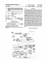
1
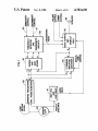
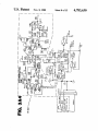
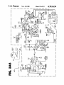
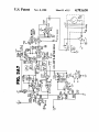
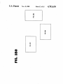
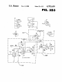
United States Patent ‘[191
Shoemaker
[11]
[45]
[54] METAL DETECTOR WITH CIRCUITS FOR
AUTOMATICALLY SCREENING OUT THE
EFFECTS OF OFFSET AND MINERALIZED
[57]
Donald K. Shoemaker, Sweet Home,
Oreg.
quadrature phase detectors, one of whose outputs is
approximately in phase with the ground component of
[21] Appl. No.: 844,797
[51]
[52]
[58]
the loop return signal. That output is modi?ed, during ‘
Mar. 27, 1986
an air balance of the detector, to remove the residual
offsets in the circuit. This modi?ed output in turn is
summed with the other phase detector output to pro
Int. Cl.4 ...................... .. G01V 3/11; GOlR 33/00
US. Cl. ............................ .. 324/329; 324/233
Field of Search .............................. .. 324/326-329,
duce a phase detection signal that can be adjusted by
automatic means to be precisely in quadrature with the
ground component of the loop return signal. A control
ler is provided, with selectable user inputs, to initiate
the static and dynamic GEB operations. An error am~
324/233
[56]
References Cited
U.S. PATENT DOCUMENTS
4,303,897 12/1981 Podhrasky ...................
4,387,338
4,470,015
ABSTRACT
as the system is used. The circuit includes a pair of
Home, Oreg.
[22] Filed:
Nov. 8, 1988
the user, continual automatic GEB on a dynamic basis
[73] Assignee: White’s Electronics, Inc., Sweet
-
4,783,630
A portable transmit/receive induction balance type
metal detector having an automatic ground exclusion
balance (GEB) feature to facilitate the screening out of
the effects of mineralized ground. The circuitry pro
vides a static GEB in a single try and then, if selected by
GROUND
[75] Inventor:
Patent Number:
Date of Patent:
pli?er in conjunction with two sample/hold elements
324/324
and a variable duty cycle chopper operate in a feedback
6/1983 Hecht et al. ..
.. 324/236
9/1984 Hirschi et al. .................... .. 324/233
loop to appropriately adjust the phase detection signal.
Audible beep indications are generated to signal the
Primary Examiner—Reinhard J. Eisenzopf
user when the steps in the automatic GEB are com~
pleted.
Assistant Examiner-Walter E. Snow
Attorney, Agent, or Firm-Chemoff, Vilhauer, McClung
& Stenzel
6 Claims, 15 Drawing Sheets
LOOP
RETURN
5mm.
5°
Y
amomss
PEAuPuFsR
mo PHASE amorous
I00
x
x OFFSET
—-
x
____+
CANCEL
sAuPLE/Rom
5am
H
LOOP
orrss'r\
mm“-
20
mscmac:
CONTROL
m
VARIABLE nu'rv CYCLE
scum: WAVE (6592"1)
(IO
vomaz-m
DUTY-CYCLE Dc CONTROL
xurr. osc.
.
mo
muz/ LOOP omv:
smEwAvE
)
AUDIO
6592":
new:
scum: wsv:
mama
vomse
I30
I
k
' W
G SUMMING
MPUFTER
GAIN STAGE
CHOPPER
I20
LAGES FEEDBACK PATH
‘55R
CONTROL
LOGIC
US. Patent
Nov. 8, 1988
Sheet 4 of 15
.M4U0E
-.(0.6-.
.G-n946
4,783,630
US. Patent
Nov. 8, 1988
Sheet 5 0f 15
4,783,630
—
bO VOU
~10m$_
2-3.58
a“:3m3% 5.?3F
#
m
W
n.
.3
h
C>3524”;
5
_
pt
lAowo-0eE
97m .
F.
[In
.U-nr49_
US. Patent
Nov. 8, 1988
Sheet 9 of 15
4,783,630
FIG. 3A5
.O2Hl30
D
_.8
7DR79.R
4.
w
IaT
LA“
M
_C.WC
0:v.
mo
R3elmD
?B9L/¢T4.OT7\'7.
B_.u
RA56r0
REa1LC_*
_
n
"w
.O _
mJ
\
aI
“a;
m
4
m
o
W.
TT
K|
I_2K5KF
C
T.IZEN.w..N.00
w“
8mm
+
5...35.4.L%
B +2m
M"K
Run.»
lM2+VH.
IE4
vF
v.94
a
RM
Ma.
L8 M
:v.
#GIT
aw.TWU
0l 03¢./
5b (\ V7.*
R5.C
-PTOQ-I.
m
.h
4.
M”:
ua+1m
Q.O
.0_NO7.1+»
Y
9.“RIMm
MlR5Y
Mm
2
5m
cv‘.7
o
Q
.wc
17i4In.
vWWW
“1
0v
LN.-.1R
’
:1CNl WWW
RBFlME0IR3
um. .»
K
mm
ax
w... x
bm
L
80
w
_M.
4.2m.
swo.H
W72|1
0
m
“a
5:.L+
z5
3
6%MI.E
CT'RO51r5+
P3
4:w
M
.Z.
B4I
_
w
m
M
%
N3MU
4U.»
uI A
IE
M
tTW“
5N
7..KDL47
Hbl“I
#5,
v
T
.0
3
.I
US. Patent
Nov. 3, 1988
Sheet 10 of 15
4,783,630
IJ
2102 020
Dim
Hm
o0n20e
at: 202
US. Patent
Nov. 8, 1988
Sheet 12 0f 15
.09“0
:6120.
4,783,630
US. Patent
Nov. 8, 1988
Sheet 13 0f15 I
4,783,630
US. Patent
Nov. 8, 1988
.
Sheet 15 01' 15
4,783,630
FIG. 3B3
+
-
9
1/4 cums
‘
a
|°_
1/4
u1 , c 1
1.11324
I’
*6]
1/1 cums
H
1""“—9<
u‘ l D
10
12
I-
+
$1‘
'20
mull H
-
V6 :04 e9
7
I
_
__
9-1
BB
2
I0
'
I
_
see 511mm arr-I
I
__
_
XQRE‘HRN
1-15
l
cows;
I
L-—_____]
L __
X B-OFFSET FIJJJST
__X‘_______|
I00
|
15
, -° um
1/3
|
1/4 cums
US 1 n
13]
1F‘
1
4,783,630
2
ment for search and ?nd activity, with the offset or‘
METAL DETECTOR WITH CIRCUITS FOR
AUTOMATICALLY SCREENING OUT THE
EFFECTS OF OFFSET AND MINERALIZED
GROUND
adjustment in the loop circuit required to screen out the
ground mineralization effects provided automatically,
and then have this screening in effect, without further
ado, as he/she proceeds over an area even though the
ground’s mineralization content might change dramati
BACKGROUND OF THE INVENTION
The present invention relates to an apparatus and
cally.
In an exemplary embodiment of the present invention
an air balancing operation is performed by the instru
ance in portable hand-held metal detectors of the induc l0 ment’s circuit, in response to operator switch actuation,
tion balance transmit/receive type in popular use today
while momentarily holding the unit with its search head
for searching and ?nding metal objects lying on or
up in the air and away from any metal objects. An audi
buried just beneath the surface of the ground. Such
ble beep tone signals the completion of this “air bal
method for providing automated ground exclusion bal
detectors are held by the operator and moved or swept
ance” cycle. The operator then places the loop on or
over the surface of the ground, and, when the detector 15 very near the ground and switches the instrument to the
passes over a metal object, the disturbance of a mag
“ground balance” cycle. The instrument’s control logic
netic ?eld created in the area of the detector’s search
circuit then proceeds to automatically make the neces
loop, as generated by a transmit coil signal and moni
tored by a receive coil, unbalances the coil loop circuit
sary changes in the loop circuit parameters to accom
plish ground effect elimination, and when this step is
completed a second audible beep occurs, thus signaling
and causes the detector to produce a visual or audible
indication of the presence of the metal object. Such
instruments have in recent years become quite sophisti
cated in operation, suf?ciently so that, by responding
not only to the amplitude of the magnetic ?eld distur
bance but also to the shift in the phase angle of the
that the instrument is ready for use. The user can then,
if desired, empirically con?rm that the instrument is
indeed ground balanced by listening for any change, in
25
received or target signal relative to the transmitted
signal, an approximate indication can be provided by
the detector as to the type of metal object located, e.g.
either direction, in the threshhold tone as the loop is
moved over the ground in an area free of targets. After
this static GEB has been accomplished the operator
can, if ‘desired, maintain the detector in ground balance
automatically as he/she uses it. The instrument is pro
the type of metal coin involved, penny, nickel, dime, 30 vided with a self-adjusting, or dynamic, ground balanc
ing feature which, as the loop is swept over the ground,
quarter, etc. However, before utilizing these detectors
a tracking circuit operates, under operator switch selec
to search for and locate metal objects it is ?rst necessary
tion, to automatically incrementally adjust the loop’s
to adjust the loop circuit to screen out the effects of the
circuit parameters, as needed, to maintain the unit in
mineralized ground in the area. The compensation or
adjustments to the detector’s search head loop circuit 35 ground balance even as the mineralization content of
the soil changes. The instrument, in the illustrative em
for such earth effects, referred to herein as “ground
bodiment herein described, is also provided with a sen
exclusion balance” or, more simply, “GEB,” was com
sitivity-adjustable knob setting to enable the user to
monly carried out prior to the present invention by
coins as opposed to aluminum pull-tabs, and even as to
cut-and-try manual techniques in which the operator
regulate the operation of the tracking circuit so that
would ?rst reset the detector instrument in air to cancel 40 target objects within the instrument’s range will not
all offsets and to set a low but discernible audio tone
inadvertently be tuned out. In a preferred form of the
level in the detector, and then hold it on or just above a
invention the detector is additionally provided with a
patch of ground known or believed to be free of metal
user-selectable “preset” or factory ?xed setting on its
objects. The change from air to ground typically would
sensitivity control which enables a novice operator to
cause either a marked decrease or increase in the audio 45 obtain satisfactory performance with the unit with a
tone, and the operator would next respond by changing,
minimum of fuss (however, an experienced user will
through manipulation of a knob setting on the instru
invariably desire to set his/her own level of sensitivity
ment, the parameters of its detector circuitry to change
in the instrument, particularly when searching unusual
the tone level in the opposite direction. The operator
would then repeat the reset step, again change the
ground balance setting, and continue this sequence as
many times as necessary until the change in tone level in
going from air to ground, or back, was either eliminated
terrain.) Selection of the preset setting on sensitivity
locks out the sensitivity knob control and prevents the
user from turning the sensitivity control up so much
that the ground balance tracking circuit does not work
properly. Use of the preset setting enables the instru
or reduced to an acceptable minimum level. Such man
ment to be used effectively after a short while, even
ual GEB adjustment, as can readily be appreciated from 55 without performing the GEB steps referred to previ
the foregoing description, was tedious and time-con
ously, as sweeping of the detector back and forth over
suming, and the procedure had to be repeated whenever
the ground in searching will cause the tracking circuit
the mineralization content of the ground changed ap
to eventually, in about 30 to 50 sweeps (the number
preciably as the operator worked over an area.
SUMMARY OF THE INVENTION
The present invention provides a control logic circuit
means for automating this GEB operation, both staticly
and dynamically, the latter referring to the GEB func
tion being performed by the instrument on a continual, 65
automatic basis as the detector is used to search over an
area. As a consequence the operator, using a metal
detector with this feature, can quickly set the instru
required being determined by the amount the instru
ment is initially off-range from the GEB condition),
bring the loop circuit into ground balance. In the track
ing circuit provided in the automated GEB system of
the present invention the adjustment in the detector
circuit’s parameters is made on each sweep of the search
head as it approaches the low point nearest to the
ground. Thus, for best results, the operator should im
plement the initial, or static, GEB with the loop resting
on or very near the ground, and then search by sweep
3
4,783,630
4
the nearby environment. Targets coming within the
ing the loop as close to the ground as possible. If condi
tion of the ground changes as the operator moves about
the area the tracking circuit will adjust the loop circuit
to keep the instrument in ground balance at all times
area of the transmit coil’s ?eld change the loop return
signal produced in the receive coil’s windings which are
connected to a Band Pass Preampli?er and Phase Quad
rature Detectors 50. The Band-Pass Preampli?er por
tion boosts and buffers the loop return signal and re
' without need for operator intervention.
Other objectives, features and advantages of the in
vention will be apparent upon consideration of the fol
duces the gain for frequencies far from the Transmit
lowing detailed description of the invention, taken in
Oscillator’s frequency. The Phase Detectors are sub
conjunction with the accompanying drawings.
stantially identical and serve as a balanced demodulator
BRIEF DESCRIPTION OF THE DRAWINGS
FIG. 1 is a block diagram of an illustrative example of
a metal detector of the induction balance transmit/
receive balance type, with no provision for an auto
X and Y component quadrature phase detector system.
The two respective outputs X and Y of the Phase De
tectors are summed in GEB Summing Ampli?er 60 and
output as a phase shift signal G which is a function of
the amplitude of the loop return signal as well as of the
15 difference in phase between the respective transmit and
matic ground exclusion balance feature.
loop return signals. A GEB Control 65 enables the user,
FIGS. 2A and 2B block diagram of the metal detec
tor embodiment of FIG. 1 modi?ed to include an auto
prior to the summing, to vary the gain of one of the
matic ground exclusion balance feature in accordance
with the present invention.
quadrature signal components, exemplarily X, corre
sponding to the ground component, while maintaining
FIGS. SAG-3A7 and 3B0-3B3 are electrical sche
matic diagrams of an exemplary circuit embodiment of
the metal detector of FIG. 2 having the automatic
ground exclusion balance feature of the present inven
tion.
FIGS. 3A0 and 3B0 are diagrams illustrating the 25
the gain of the other component at unity. These three
phase signals, X, Y and G, are then passed through
Filters and Gain Stages 70 and supplied to a Threshold
Detector 80 which also includes Discriminater Circuits
for responding to and generating as an output to the
Speaker 40 an audio indication of the presence of target
layout arrangement of the electrical schematic diagrams
objects in the ?'eld of the search loop. Knob switch/set
of FIGS. 3A1 to 3A7 and 3B1 to 3B3 respectively.
ting controls 90 and 91 are provided to enable the oper
ator to vary, respectively, the degree of sensitivity of
DETAILED DESCRIPTION OF THE
the instrument and the degree of discrimination as be
INVENTION
30 tween target objects of different response characteris
tics.
An illustrative embodiment of a metal detector of the
The foregoing description is of a conventional metal
described type having the automatic ground exclusion
detector system circuitry in which GEB is effected by
balance (AGEB) feature of the present invention is
currently manufactured and marketed by applicant’s
assignee, White’s Electronics, Inc., of Sweet Home,
the user’s manual twiddling and adjustment of the GEB
35 Control setting 65 in the manner described earlier.
FIGS. 2A and 2B depict the same simpli?ed metal
detector system with the addition of the AGEB feature.
(In this diagram elements labeled with the same refer
Oreg., under the model name and trademark COIN
MASTER 6000/Di Professional (hereinafter referred
to as the “6000/Di Pro”).
The operator’s manual for the 6000/DiPro instru
ment, published by White’s Electronics, 1110., describes
ence numerals are substantially the same as the similar
40
the manner in which the AGEB feature is utilized by
the operator through panel switch settings and manipu
ly-labeled elements in FIG. 1.) In providing AGEB,
offsets in the loop circuit present in the X, or ground
component, of the loop return signal, as derived by the
Quadrature Phase Detectors 50, are cancelled out by
lations of the instrument’s search head. While such
description has been summarized earlier herein and is
the X Offset Cancel 100 in response to an appropriate
non-essential to an understanding of the nature and 45 actuating signal 102 from the Control Logic Module
110 when the user selects the “Air” position at 115.
manner of operation of the present invention, it is useful
in understanding its background and operational envi
(Offsets refer to the residual DC levels in the output of
the Phase Detectors.) The offset to the X component
ronment. Accordingly, that publication, to the extent
pertinent hereto in respect to the AGEB feature, is
herein incorporated by this reference.
signal is maintained by the Sample/Hold portion of this
50 element 100 until a subsequent time (to be described
Referring ?rst to FIG. 1, there is shown a simpli?ed
block diagram of a transmit/receive type induction
balance metal detector, corresponding to the Model
6000/Di Pro, but without the AGEB feature included.
The instrument comprises a Transmit Oscillator and
Loop Drive 10 which causes a sinusoidal waveform to
be produced in to the Search Loop 20 as well as provid
ing an audio tone signal, supplied via Audio Output 30,
to the Speaker 40 which provides an audible indication
to the operator of the status of the loop’s balance circuit.
The Audio Output 30 is preferably provided with a
user-actuatable Sample/Hold circuit-~a conventional
feature-~to allow offsets in the input to the audio stage
to be cancelled. The Search Loop 20, as is conventional,
comprises a pair of coils-a transmit coil driven by the 65
Transmit Oscillator which generates a magnetic ?eld in
the area of the search loop and a receive coil which is
responsive to changes in that magnetic ?eld caused by
later) when a disable signal is supplied thereto from the
Control Logic module via Discharge Control line 104.
The Summing Ampli?er 60 determines the phase G of
the loop return signal relative to the transmit signal by
inversion summing of a ?xed multiple of the Y compo
nent with a variable multiple of the X component. The
adjustment a applied to the X component at the Sum
ming Ampli?er is accomplished through the use of a
Chopper 120 whose duty cycle, between zero and
lOO%, is determined by the DC Control Voltage level
131 applied to Converter 130. The square wave signal
132 determines the frequency of the Converter’s output.
In other words, the duration of the duty cycle, corre
sponding to the adjustment on, is responsive to the out
put 131 of the GEB Sample/Hold 170.
In the air balance mode of operation the Error Am
pli?er 150, through a feedback loop which is enabled by
a control pulse 162 from the Control Logic module,
'
5
4,783,630
forces the output 164 of the Air Sample/Hold 160 to
6
An exemplary electrical schematic of the circuitry of
the system, depicted in block diagram form in FIGS.
2A and 2B, is shown in FIGS. 3A1-3A7 and 3B1-3B3.
Sections of the circuitry have been partitioned off by
match the level of the G signal supplied from the Sum
ming Ampli?er 60. A beep indication, signifying com
pletion of the air balance step, is provided by the Audio
Drive 30 upon the enabling of the feedback loop in
dashed lines and labeled with reference numerals corre
response to a pulse on the reset line 35 provided by the
sponding to those of the corresponding elements in the
Control Logic module. Output 164 is held until the
block diagram of FIG. 2. Component elements in the
schematic, and their respective values, are shown using
standard industry nomenclature.
ground balance step (described later) is completed. The
Error Signal output 152 is provided as an input to GEB
Sample/Hold 170 whose function is to provide the
Control Voltage level 131.
In the ground balance mode the Error Ampli?er,
through an AGEB Feedback Path which is enabled by
The terms and expressions which have been em
ployed in the foregoing speci?cation are used therein as
terms of description and not of limitation, and there is
no intention, in the use of such terms and expressions, of
control signals 171, 172 from the Control Logic mod
ule, forces the output of the GEB Sample/Hold to
match the G signal supplied from the Summing Ampli
excluding equivalents of the features shown and de
scribed or portions thereof, it being recognized that the
scope of the invention is de?ned and limited only by the
claims which follow.
this matching accomplished, the G signal in ground
What is claimed is:
balance mode has been automatically modi?ed, through
1. In an induction balance transmit/receive type of
adjustment of the X component signal, to equal the G 20 portable metal detector having an oscillator, a search
signal level in air balance mode of the detector system.
head with a transmit coil driven by said oscillator to
This corresponds to the static balance operation de
produce a magnetic ?eld and a receive coil producing as
scribed earlier. When this step is completed the GEB
an output a loop return signal responsive to changes in
Sample/Hold 170 is caused to hold its output level 131
said magnetic ?eld caused by the nearby environment, a
by the control signals 171, 172; at the same time the X 25 pair of phase detectors receiving said loop return signal
Offset Cancel 100 is disabled by the control signal 104. ' and producing a pair of component signals in quadra
An audio beep indication, signaling that this has oc
ture, means for adding said component signals together
curred, is provided by the Audio Drive 30 in response
to produce a phase detection signal, and, indicator
to a pulse on the reset line 35 provided by the Control
means responsive to the amplitude of said phase detec
?er 60 to the output 164 of the Air Sample/Hold. With
Logic module.
30
If it is desired that the system perform a dynamic
ground exclusion balance as earlier described, then the
user selects the “Gnd” position at 115, otherwise this
feature is disabled. In the dynamic GEB setting a Slope
Detector 180, responsive to the derivative of the X 35
component signal, provides a Ground Signal 182 whose
polarity is indicative of the direction of the X compo
nent’s slope. For example, a ?rst polarity signi?es the
Search Loop 20 approaching the ground, and the other
polarity, moving away or no movement relative to 40
ground. A change in that signal from the ?rst to the
second polarity signi?es the point at which the search
loop is closest to the ground. As the Search Loop
moves away from ground or is static, as monitored by
the Slope Detector, the Error Ampli?er 150 functions
as when in the air balance mode to force the Air Sam?
ple/Hold output 164 to match the Summing Ampli?er
output G. When the Search Loop approaches the
ground, the output 164 is held (as before), and in re
sponse to a control signal from the Control Logic on the
Slow Adjust line 172 the AGEB Feedback Path is
closed and the DC Control Voltage 131 is adjusted (as
described before) in response to the Error Signal 152
produced upon the matching of Summing Ampli?er
tor signal, the improvement comprising:
(a) air balance circuit means, responsive to said phase
detector signal when said search head is held away
and remote from the ground, for automatically
adjusting said phase detection signal level so as to
cancel out offsets occurring in said loop return
signal;
(b) static ground balance circuit means for screening
out on a one-time, user-actuatable basis ground
effects, said ground effects being the effects on said
loop return signal of the mineralization content of
the ground in the vicinity of said metal detector;
(c) dynamic ground balance circuit means for screen
ing out on a continuing, repetitive basis said ground
effects; and
(d) user-selectable switch means for transferring said
metal detector being two modes of operation, the
?rst mode utilizing said air balance circuit means to
adjust said phase detection signal to an air balance
level of said detector, and the second mode utiliz
ing said static and said dynamic ground balance
circuit means to provide a screening out from said
phase detection signal of said ground effects.
2. The metal detector of claim 1 including control
means for varying the sensitivity of said detector in
output G to the Air Sample/Hold output 164. In this 55 responding to the mineralization content of the ground
dynamic GEB mode of operation a slow adjustment
in the vicinity of said detector.
rate, exemplarily about ten times the time constant of
3. The metal detector of claim 1 including means for
the fast adjustment rate used in the static balance mode,
providing an indication when said air balance circuit
is utilized to limit the speed of the correction provided
means has completed said adjustment.
by the AGEB Feedback Path. This is preferably done, 60 4. The metal detector of claim 1 wherein said dy
while in this mode, so as to minimize the error which
would otherwise occur due to the presence of offsets in
the X component signal. (During dynamic balance, it
will be recalled, the X Offset Cancel 100 is disabled.) If
namic ground balance circuit means has a circuit time
constant which is at least an order of magnitude larger
than the circuit time constant of said static ground bal
ance circuit means so as to slow the response and
the unit were left at a fast adjustment rate, for example 65 thereby avoid hunting in the operation of said dynamic
a circuit time constant of one second as opposed to ten
seconds, the circuit would hunt back and forth around
the correct GEB setting.
ground balance circuit means. '
5. The metal detector of claim 1 wherein a ?rst indi
cation is given when said metal detector has completed
7
4,783,630
8
responsive to both a change in the distance of said
search head from the ground and the direction of said
an air balance operation and a second indication is given
when said metal detector has completed a static ground
balance operation.
change, said output signal being utilized in said dynamic
6. The metal detector of claim 1 characterized in that
said dynamic ground balance circuit means includes
slope detector means for producing an output signal
ground balance circuit means for screening out said
ground effects.
*
1.0
15
20
25
35
45
50
55
60
65
*
*
1K
*