1
Power Factor Controller BR6000-T6R6
for combined dynamic and standard compensation
Manual
Version 4.0 E
EPCOS AG
Power Quality Solutions
P.O. Box 80 17 09
D-81617 Munich
St.-Martin-Str. 53
PFC-Hotline
Tel. ++49 89 636 - 25533
Telefax ++49 89 636 - 22748
internet: http://www.epcos.com
!
CAUTIONS:
1. High voltage !
2. BR6000 may only be used indoor !
3. Make sure that discharge time set in controller matches capacitor discharge time !
Power Factor Controller BR6000-T6R6
CONTENTS
Section 1
General / type series and accessories
2
Section 2
Installation of the controller / connection diagram
4
2.1
2.2
2.3
5
Current measurement
Programming of phase-correction
Alarm output / error messages
6
Section 3
Operating modes
6
Section 4
Automatic operation / display functions
7
Section 5
Programming
5.1
5.2
Program menu
Programming lock
8
11
Section 6
Manual operation / Programming of fixed stages
12
Section 7
Service menu
13
Section 8
Expert mode
13
8.1
8.2
14
Expert mode 1
Expert mode 2
Section 9
Control principle
15
Section 10
Interface
16
Section 11
Initial operation
16
Section 12
Maintenance and warranty
16
Section 13
Troubleshooting
17
Section 14
Technical data
18
Annex:
Annex 1
Annex 2
Annex 3
Annex 4
Annex 5
EPCOS FK PM PFC
Table of control series
Description of control-series editor
Default settings
Application MMI6000
MODBUS protocol
Operating diagram (fast programming)
-1-
19
20
21
22
24
Version 4.0 E, Sept. 2007
Power Factor Controller BR6000-T6R6
Section1 General
The mixed dynamic power factor controller BR6000-T6R6 represents the consequent
follow-up development in the BR6000-series bringing innovative ideas und a multitude of
new functions.
It is especially designed for triggering of up to 6 thyristor modules and at the same time
up to 6 standard capacitor contactors in combined standard-dynamic PFC-systems.
The switching time of < 20 ms for the dynamic steps delivers extremely fast
compensation adjustment for fast changing loads.
Several parameters that can be edited allow an optimized adjustment to different
thyristor modules.
The controller is distinguished by user-friendly operation based on menu-guided displays
in plain text. Its new features permit an intuitive mode of operation. Easy-to-understand
symbols and texts in 8 local languages combine simplest operability with self-evident
displays.
Main features:
R
R
R
R
R
R
R
R
R
R
R
R
R
R
R
R
R
6 transistor- and 6 relais- switching outputs
pre-programmed control series with a self-optimized intelligent control response
Control-series editor for user-defined control series
Complete menu-guided operation and display
Illuminated graphic display with 2 x 16 characters
Four-quadrant operation
Display of various line parameters (V, I, F, Q, P, S...)
Display and monitoring of temperature
Monitoring of capacitor power values with accessory MMI6000
Storage of maximum line-parameter
Manual / automatic operation
Programming of fixed stages and the option of skipping individual outputs
No-voltage turn-off
Error detection for various states and interference-message output
Error memory
2nd target power-factor possible
Switchboard-integrated housing 144x144x55 mm
Type series and accessories
BR6000-T6R6
6 transistor outputs, 6 relay outputs, 1 alarm relay
BR6000-T6R6/S
-
Accessories
- Meas. voltage adapter for grids without “N” or voltages > 300V
- MMI6000 - MultiMeasuringInterface
(for measurement of inherent current of capacitor bank )
EPCOS FK PM PFC
6 transistor outputs, 6 relay outputs, 1 alarm relay
1 additional user programmable message relay,
input for second target power factor
with an additional interface RS232 or RS485
-2-
Version 4.0 E, Sept. 2007
Power Factor Controller BR6000-T6R6
The controller is supplied as standard for an operating voltage of 230 VAC (L-N), a
measuring voltage of 30...300 VAC (L-N) 50/60 Hz and a measuring current of 5A or 1A
(programmable). A voltage converter is required for different operating voltages.
Caution!
Voltages which exceed the allowed voltage range can damage the
device !
!
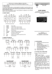
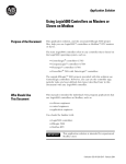
Fig.1 BR6000 front view
Operating mode
- Automatic
- Programming
- Manual operation
- Service
- Expert mode
Power Factor Controller
1 2 3 4 5 6 7 8 9 10 11 12
BR 6000
Auto
Program
Manual
Service
Enter / OK
Confirm and
store values
Increase
selected
parameter
Enter
OK
Reduce
selected
parameter
Power Quality Solutions
Fig. 2 BR6000 rear view
Power factor controller
type: BR6000-T6R6
meas. voltage: 30 -300V L-N 50/60Hz
supply voltage: 230V L-N
50/60Hz
Ser.No.: 0815 / 2007
supply voltage
Ub
me as.
voltage
Um
me as.current
Im (5A/1A)
k
l
L1 (R)
L2 (S)
L3 (T)
T 2A
T 2A
PE
L
N
L
Ub
N
k
Um
l
Im
power factor controller BR 6000T6R6
transistor outputs
a
b
P1 1
2
3
4
5
relay outputs
6
P2 7
8
9 10 11 12
1
2
3
extern
alarm
relay
supply
voltage
L
meas.
voltage
N
L
meas.
current
N
k
RS 485 (Option)
GND B
A
SL
EPCOS FK PM PFC
alarmrelay
l
a
extern
1
2
transistor outputs
b
message
relay
3
4
message
relay
4
P1 K1 K2 K3 K4 K5 K6
relay outputs
P2 K7 K8 K9 K10 K11 K12
-3-
Version 4.0 E, Sept. 2007
Power Factor Controller BR6000-T6R6
Section 2 Installation and connection of the controller
The BR6000 is designed to be incorporated into the front panel of a PFC-cabinet. It
requires a switchboard section of 138 x 138 mm to DIN 43700/ IEC 61554. The controller
is inserted from the front and is attached by means of the appended clamps. The
controller may be inserted only by qualified technicians and must be operated in
accordance with the specified safety regulations.
Before the BR6000 is connected up, all leads and cables must be checked to ensure that
no current is flowing through them and the current converter must be short-circuited.
Care should be taken to ensure that the measuring voltage and current are in the correct
phase position. The measuring-current circuit must be wired with copper leads of
2.5mm2. The connection should be set up as shown in Fig. 3. The specified safety
regulations must be observed.
The measuring voltage may lie in the range from 30 - 300 V and is connected between
L1-N (corresponds to 50 - 525 V L-L ). A connection between L-L is possible if a
measuring-voltage converter is used and the corresponding phase shift U-I is
programmed (see Programming).
For higher measuring voltages, a measuring voltage adapter is available as an accessory.
The operating voltage is 230 V +/- 10% and can be connected between L1 - N in a 400-V
grid.
The coil voltage for the capacitor contactors and the measuring voltage
must be drawn from the same phase conductor, as only the measuring
voltage is monitored. (Protection against direct reconnection of the
capacitor contactors in the event of momentary single-phase power
failure)
!
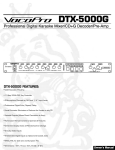
Fig. 3: BR6000 Connection plan
supply
voltage
Vb
meas voltage
Vm
meas.curre nt
Im (5 A/1A)
k
1. capacitorbra nch
dynamical step
l
7. capacitor
bra nch
(re lay output)
L1 (R )
L2 (S )
L3 (T )
L
Ub
N
T 4A
T 2A
T 2A
N
PE
L
N
k
Um
l
P2
TSM-LC
K1
Im
power factor controller
BR6000-T6 R6
+-
relay outputs
transistor outputs
1
2
3
4
5
6
7
8
9 10 11 12
P1
thyri stor switches 1-6
capacitorcontactors 7-1 2
+24V-
EPCOS FK PM PFC
-4-
Version 4.0 E, Sept. 2007
Power Factor Controller BR6000-T6R6
2.1 Current measurement
When installing the current converter, care should be taken to ensure that the load
current flows through it. The outputs of the compensation network must be installed
behind the current converter (in the direction of current flow). If the BR6000 is
connected up via sum-current converters, the overall conversion ratio is entered.
Measurement via sum current converter
!
Feed 1
Caution !
Current converter clamps should
be grounded on one side !
Feed 2
K
k
L
l
K
Example:
C.converter 1: 1000/5A
C.converter 2: 1000/5A
Sum-current converter: 5A+5A/5A
L
K
k
k
K
l
L
L
l
k
l
Current
measurement
C.converter ratio is: 2000/5A
BR6000
2.2 Programming of phase-correction
Adjustment of phase-correction between voltage and current in the meas. system is done
in expert mode 1
supplyvoltage
Vb
meas. voltage
L2-L3
Meas.current
k
l
L1 (R)
Example:
L2 (S)
BR6000
T 2A
T 2A
L3 (T)
N
PE
Meas.current: L1
Meas. Voltage L3-L2
( V-converter
must be used)
L
N
Ub
Phase U/I [ 90°]
L
N
k
Um
l
Im
using
meas. current
meas. voltage
volt.transformer phase-angle
standard
L1
L1
L1
L1
L1
L1
L1
L1
L1
L1
L1
L1
L1
L1
L2
L3
L3
L3
L1
L1
L2
L2
L3
L3
no
necessary
no
necessary
no
necessary
no
necessary
no
necessary
no
necessary
EPCOS FK PM PFC
(k<->l)
(k<->l)
(k<->l)
(k<->l)
(k<->l)
-
N
L2
N
L2
N
L1
N
L2
N
L3
N
L1
-5-
0°
30°
60°
90°
120°
150°
180°
210°
240°
270°
300°
330°
Version 4.0 E, Sept. 2007
Power Factor Controller BR6000-T6R6
2.3 Alarm output / error messages
The alarm contact is closed in normal operation and opens in the event of a fault. The
relevant fault is simultaneously shown on the display in plain text (alternating with the
standard display in automatic operation). The following fault messages are displayed:
UNDER-COMPENSATED
OVER-COMPENSATED
OVERCURRENT
MEASURING VOLTAGE ?
OVERTEMPERATURE
OVERVOLTAGE
UNDERVOLTAGE
Display and relay output
Display and relay output
Display and relay output
Display and relay output
Display and relay output
Display and relay output
Display and relay output
Additionally several messages for different operation states are generated. An individual
adjustment resp. suppression of particular messages is possible in expert mode 2. During
suppression, the indication of the message in the display, a possible release via alarmrelays and effects on the controlling process will be prevented.
Section 3 Operating modes
When the operating voltage is switched on, the BR6000 briefly displays its designation
and software version, then changes to its normal operating status (automatic operation).
The active cos-phi value is always displayed in the upper line and the currently connected
capacitors are shown as symbols in the lower line (operating display).
The control direction is symbolized
by a closed arrow
Automatic operation
Display of active power-line cos phi
Display of “Fan”-option
Connecting-in
Connecting-out
The connecting-in arrow is always
located after the maximum possible
number of stages (end stop)
An open arrow indicates that the
required blocking time (discharge
time) is running before an impending
switching step
Active capacitor
branches
Control direction
(here connected-in)
Supply display (for
4-quadrant operation)
A double arrow symbolizes fast
switching of several branches
Transfer-mode
dynamic -> static section
Repeated pressing of the "Operating Mode” key takes the user to the various menus in
sequence: Automatic operation - Programming Manual (manual operation)Service - Expert mode and back.
Automatic oper.
Programming
Manual operation
to display operation
to programming
to manual operation
EPCOS FK PM PFC
-6-
Service
to value buffer
Expert mode
to special functions
Version 4.0 E, Sept. 2007
Power Factor Controller BR6000-T6R6
Section 4 Automatic operation - display of network parameter
The BR6000 is set to automatic operation as standard. Capacitor stages are then
automatically connected in or out in order to reach the target power factor. This happens
when the required reactive power exceeds the value of the smallest capacitor stage.
In automatic operation, various network parameters can be displayed by repeatedly
pressing the "ENTER” key:
Action
Display
ENTER
ENTER
ENTER
ENTER
ENTER
ENTER
ENTER
ENTER
ENTER
ENTER
1 LINE VOLTAGE
in V
2 APPARENT CURRENT
in A
3 REACTIVE POWER
in kvar
4 ACTIVE POWER
in kW
5 APPARENT POWER
in kVA
6 DIFF. kVAR TO TARGET COS
7 FREQUENCY
in Hz
8 TEMPERATURE
in °C
Software version
Return to: 1
/ %
/ %
/%
/%
/ °F
The power value specifies the total power (3-phase) assuming symmetrical load. If no
key is pressed for 60 seconds, the display automatically returns to the operating status!
principle circuit of the transistor output
Switching outputs
Switching outputs:
The first 6 switching outputs of the BR6000-T6R6 are
executed as transistor outputs.
X2:1
to thyristor module
( e.g. TSM-LC...)
These are used via an additional auxiliary voltage
(10...24 VDC) for direct triggering of thyristor
modules for dynamic power factor correction.
Max. current for a single output: 40 mA
Total current of all outputs: max 150 mA
Outputs 7…12 are relay outputs with potential free,
normally open contact for max. 250 VAC
Max. current for a single output: 6A
Max. current of all outputs: 10 A
X2:2
Further stages
X2:6 (12)
J
P1 200mA
+ 24VDC
!
WARNING: Mixing-up of outputs and thus applying of 230 VAC on
the transistor outputs will destroy the internal transistors !
P1= +24 VDC for transistors, P2 = L1 (230VAC) for relays
EPCOS FK PM PFC
-7-
Version 4.0 E, Sept. 2007
Power Factor Controller BR6000-T6R6
Section 5
Programming
Pressing the "Operating mode” key once takes the user from automatic operation to
Programming mode.
The upper display always shows the parameter and the lower one the set value. The
values are changed by pressing the é / ê keys. Subsequent pressing of the "ENTER” key
stores the value and takes the user to the next parameter.
To quit programming mode in any step, press the "Operating mode” key.
Selection of different values for the transistor resp. relay section is marked by symbols
T resp. R .
5.1. Program Menu
LANGUAGE SELECTION: This selects the language of the operating menu
(German, English, Spanish, French, Russian, Czech, Dutch, Polish)
1 I-CONVERTER PRIM: [ 1000]A
( 5...13000)A
This selects the primary current of the current converter. Adjustment is
via the é / ê keys. Save and continue with ENTER
2 I-CONVERTER SEC:
[ 5 ]A
(5/1)
This sets the secondary current of the current converter
Selection via é / ê. Save and continue with ENTER
3 END STOPP:
T
(dynamical part) ( 1...6 )
By setting the end stopp, the number of active capacitor branches is
matched to the respective capacitor bank. This is done via the é / ê
keys. The visible symbols of the capacitors correspond to the connected
outputs.
4 CONTROL SERIES:
(dynamical part) ( 1...20 + E )
The ratio of the capacitor branch power determines the control series,
the power of the first capacitor always being assigned the value 1. The
control series required for the compensation network is again selected
via the é/ê keys. If the required control series should exceptionally not
be present (Annex 1), the user may define a special one (control series
"E”). More on this point in the control-series editor in Annex 1.
Save and continue with ENTER
T
5 CONTROL PRINCIPLE: (dynamical part)
The control preference may be selected here:
T
SEQUENTIAL connection
LOOP connection
INTELLIGENT loop connection (default setting)
See Section 9 for an explanation of the various control modes.
EPCOS FK PM PFC
-8-
Version 4.0 E, Sept. 2007
Power Factor Controller BR6000-T6R6
6
T
POWER 1. STAGE: (dynam. part)
( 0.01 ... 255.99 ) kvar
To determine the controller's response sensitivity, the dimensions of the network's
smallest capacitor (stage 1) must be known. They are entered in two steps in kvar.
The integral kvar values (before the comma) are initially selected via the é / ê
keys and saved with ENTER. The positions after the comma are then selected,
again via the é / ê keys. If the response sensitivity of the BR6000 is being
undercut, a warning will occur ( indication of “!” in the display )
7 CONNECTING TIME (dynam. part)
( 20 ... 1000 ) ms
This refers to the time between connecting the capacitors to increase the
momentary network capacitance. It should be noted that in practical operation the
real connection time is affected by the discharge time (locking time).
Default setting:
1000 ms
Selection is performed via the é /ê keys. Continue with ENTER
T
8 DISCONNECTING TIME (dynam. part) ( 20 ... 1000 ) ms
This refers to the time between disconnecting the capacitors to reduce the
momentary network capacitance..
Default setting:
1000 ms
Selection is performed via the é /ê keys. Continue with ENTER
T
9 DISCHARGE TIME
(dynam. part)
( 20 ... 1000 ) ms
This is the time for which an individual output is blocked between connecting and
disconnecting. This blocking time has priority over connecting and disconnecting
times. It depends on the capacitor discharge rating and thus is specified by the
compensation network.
Default setting: 200 ms
Selection is performed via the é /ê keys. Continue with ENTER
T
10 END STOPP
R
(relay part)
Default: 12
(7...12)
11 CONTROL SERIES
R
(relay part)
(1...20 + E)
Default 1:1:1:1:1:1
12 CONTROL PRINCIPLE (relay part)
R
Default: Intelligent
13 POWER 1.STAGE
R
(relay part)
(0.01...255.99) kvar
Default: 25.00 kvar
14 CONNECTING TIME (relay part)
R
Default: 40 sec
(1...1200) sec.
15 DISCONNECTING TIME (relay part)
R
Default: 40 sec
(1...1200) sec.
16 DISCHARGE TIME
R
(relay part)
Default: 60 sec
(1...1200) sec.
17 EXTERNAL INPUT
possible:
[without function]
- “2nd target cosPhi”: input-signal activite 2nd target cos Phi
- “external Error”: input-signal switched off the controller
step by step
EPCOS FK PM PFC
-9-
Version 4.0 E, Sept. 2007
Power Factor Controller BR6000-T6R6
18 TARGET COS PHI:
[0.98 IND]
( 0.8 ind ... 0.8 cap )
By setting the target cos phi, the power factor to be attained via the PF correction
is defined. It is also set via the é / ê keys.
Save and continue with ENTER
19 MEASURING VOLTAGE
[230]V
( 30 ... 305)V
Programming the measuring voltage (L-N) of the system (direct measurement) or
the L-N voltage on the primary side of a measuring-voltage converter. The values
programmed here always refer to the voltage L-N in the system! The voltage is
selected via the é /ê keys. Save and continue with ENTER.
20 V - CONVERTER RATIO
[ NO ]
(NO / 1.1 ... 990 ]
When a measuring-voltage converter (e.g. for HV- measurement) is used, its
conversion ratio should be programmed here.
Example: Voltage converter 20000V:100 V => Conversion ratio: 200
Selection via the é /ê keys. Save and continue with ENTER.
21 ALARM TEMP
[ 60]°C
( 50...85)°C
The alarm temperature programmed here is the temperature at which the
capacitor stages are disconnected in steps. The controller’s alarm relay
responds after 60 seconds. At the same time the display shows the cause of the
alarm (over-temperature). If the temperature drops again, the required
branches are automatically re-connected in steps.
The selection is performed with the é /ê keys. Save and continue with ENTER.
22 MESSAGE RELAY
( available only at version with Interface )
The message relay can be programmed for one of the following options as required:
"Fan”:
(Default)
Relay switches the external cabinet fan.
The switching threshold can be programmed under point 23.
Display: "F”
"Supply":
Message when active power is supplied. Display: "S”
"Undercurrent”:This message appears whenever the measuring current is not
reached. Display: "U” The signal is generated when the value drops
below the response sensitivity of the controller.
“Module error”: Display of a default signal taken via MMI6000 (only applicable with
MMI6000 connected),
e.g. “overload system”
Control display “M”
EPCOS FK PM PFC
- 10 -
Version 4.0 E, Sept. 2007
Power Factor Controller BR6000-T6R6
23 FAN TEMP*
[30]°C
(15...70)°C
Input of the switching threshold for the fan.
* Only active if option 'Fan' is selected
24 DELAY-TIME OF ERROR-MESSAGES ( 0... 255) sec.
The delay time for error-messages in the display can be changed here.
Default: 10 sec.
CONTRAST
[7]
( 5...10 )
The display contrast can be changed with this menu point. The contrast depends to
a certain degree on the viewpoint of the observer, i.e. on the insertion height of the
equipment in the switching cabinet. The é /ê keys can be used to set an optimal
contrast.
BASIC SETTING:
[ NO ]
( YES / NO )
When the selection is made with YES and confirmed with ENTER, all parameters
are reset to the basic setting made by the PFC-system manufacturer.
(Optimal network values when the controller was supplied with a complete PFCsystem). If the controller is supplied from the works, this point corresponds to the
default setting.
CAUTION: All user settings are lost!
Programming is now completed. The controller has returned to point 1 of the
programming menu.
5.2 Programming lock
The BR6000 is equipped with a programming lock to ensure protection from unauthorized
or inadvertent changes to the system parameters. The lock can be activated in expert
mode. If the lock is active, all parameters can be checked but not changed.
EPCOS FK PM PFC
- 11 -
Version 4.0 E, Sept. 2007
Power Factor Controller BR6000-T6R6
Section 6
Manual operation (initial operation, maintenance, service)
Programming of fixed stages
In manual operation, capacitor branches can be connected/disconnected in the set
control series and switching time - irrespective of prevailing power-line conditions.
Connections are made by pressing the é or ê key.
The active operating status and active power factor are always shown on the display (selfexplanatory).
Manual operation
Pressing ENTER takes the user to the menu point "Programming of fixed stages”.
In the normal case, all stages are programmed for automatic operation (default setting).
Setting of fixed stages
AUTO OFF FIX
(Currently selected stage blinks)
In special cases, all controller outputs (C1 - C12) may be permanently defined in
succession (continued switching via ENTER) for the following statuses:
OFF: The output is continuously disconnected - e.g. for temporarily disconnecting a
defective capacitor. The capacitor symbol for this output is faded out. Underlining
appears.
AUTO: Automatic (normal) operation
The relevant output is marked by a capacitor symbol.
FIXED: The output is continuously connected, e.g. for fixed PFC. The output is
marked by an underlined capacitor symbol.
The active stage is blinking. The required status is set via é /ê. By pressing ENTER, the
user saves this step and moves to the next stage.
The programmed statuses for the outputs also remain visible on the display in automatic
operation.
After the required settings have been made, pressing the "Operating Mode” key takes the
user to the next menu ("Service”) or further to "Automatic Operation”.
EPCOS FK PM PFC
- 12 -
Version 4.0 E, Sept. 2007
Power Factor Controller BR6000-T6R6
Section 7
Service menu
The service menu is reached by the operating-mode key.
The stored maximum values of the network parameters can be displayed here.
In addition, a fault memory is available, in which the last 8 fault states of the system are
stored with fault code and in plain text. (This allows, for example, capturing short lived
events of overtemperature or overvoltage)
Action
Display
ENTER
ENTER
ENTER
ENTER
ENTER
ENTER
ENTER
ENTER
1 max. VOLTAGE
2 max. REACTIVE POWER
3 max. ACTIVE POWER
4 max. APPARENT POWER
5 max. TEMPERATURE
6 RESET the maximum values
ERROR MEMORY E [1] - ....
ERROR MEMORY RESET
ENTER
Section 8
in V
in kvar
in kW
in kVA
in °C
/%
/%
/%
/ °F
in plaintext
Back to 1
Expert mode 1 and 2
The expert mode is meant for the adjustment of values which normally should not be
changed. As a protection against mal-operation this level has an access code branching
out in Expert mode 1 or 2.
Password:
Expert mode 1: “ 6343”
Expert mode 2: “2244”
8.1. Expert mode 1
2 BASIC SETTING NEW
[NO]
( NO/YES)
Storage of active programming as a new basic setting (usually performed by the
PFC-system manufacturer). Caution: The original values are overwritten in the
process!
3 SWITCHING POWER max
[100/100] kvar (multiples of the smallest stage)
This factor specifies the maximum power which may be switched in one switching
step. It can be used to control the intelligent control system, which switches
several stages as a function of the power-factor requirement.
(This message will be displayed separately for dynamic and static part )
4 SWITCH.TRIGGER
[66]%
(30...100%)
Threshold for switching on of next stage. It should not be changed in the normal
case!
5 OPERATING LOCK
EPCOS FK PM PFC
[NO]
- 13 -
(NO / YES )
Version 4.0 E, Sept. 2007
Power Factor Controller BR6000-T6R6
6 PHASE I
7 PHASE U
[0°]
[L1] -
L1 - N
[0°]
L1 - [L1 - N]
Adjustment of current phase position
Adjustment of voltage phase position
Phase correction between voltage and current in the measuring system.
This setting allows to measure also in systems without neutral. However, the
measuring voltage may not exceed 300 V (if necessary, a voltage converter
must be used).
8
OUTPUT 1. STEP [0...255]
(0...2550)
The range for entering the stage output can be increased to [0...2550] here, (e.g.
for medium voltage measurement)
9 CONTROL
[3] PHASE
(3/1)
The measuring system of the controller is generally based on single-phase
measurement. For all standard settings (three-phase), the measurement is
converted and all outputs displayed as three-phase values (symmetry in grid
assumed). In the single-phase setting, display and control apply only to the
single-phase value measured.
(application: single-phase correction in asymmetrical grids).
10 PROTOCOL *only with option interface
[ OFF ]
[ MODBUS RTU ] MODBUS protocol for individual usage
[ ASCII OUT ]
output of grid-values as ASCII-file (s.page 16)
[ MASTER MMI ] for communication with MMI6000
Depending on the protocol selection, the appropriate configuration-menu is offered:
11
12
13
14
15
16
17
18
BAUD RATE
Number of MMI
ADDRESS
UPPER VALUE
LOWER VALUE
TEST ATTEMPT
TEST-TIME
ASCII time
[38400]
[1]
[1]
[130]%
[60]%
[10]
[10]
[10]sec.
(4800...38400)
(1 ... 3)
(1 ... 32)
(110 ...200%)
(30 ... 95%)
(3 ... 255)
(3 ... 255)
(1 ... 255)
Transmission rate
Nos of connected MMI
Address
Switch. threshold MMI
Switch. threshold MMI
Repetition-time ASCII
8.2. Expert mode 2
( Password: 2244)
The additional 2nd expert mode includes all messages for operation, warning and error
which are displayed by the BR6000. Here they may be deactivated separately. When
deactivated, the indication of the message in the display as well as possible activation of
the relay or effects on the control behavior are suppressed (detailed list of all messages in
menu plan last page).
EXPERT MODE 2
[YES]
(YES/NO)
Activation of particular operation, warning and error messages (s. above)
(16 messages in total)
ALARM TIME
[60] sec.
(0...255 sec.)
Time after which the alarm relay will respond
EPCOS FK PM PFC
- 14 -
Version 4.0 E, Sept. 2007
Power Factor Controller BR6000-T6R6
Section 9
Control principle
The BR6000-T6R6 features 6 transistor outputs for the dynamic (fast switching)
components and 6 relay outputs for the conventional capacitor steps switched via
capacitor contactor.
If needed (target cos-phi not yet achieved) always the dynamic steps will be switched in
to compensate the very fast changing loads.
In case the dynamic steps are switched in for a longer time, they transfer their load to the
conventional capacitor outputs switched by relay. This happens with respect to the preset on- and off switching times of the relay section.
By transferring the loads the steps switched by transistors are free for the dynamic
compensation.
The advantage of a mixed-dynamic compensation is the combination of a dynamic
section (fast compensation of dynamic loads) and a conventional section of the system
(for the ground load resp. for slow changing loads) in a single PFC system. By this
combination a significantly better economic solution is achieved than compared to a
purely dynamic system.
The control response of the BR6000 can be selected in programming mode. In principle,
the controller has four different control modes:
1. Sequential connection
In sequential connection, the required capacitor stages are successively connected
and disconnected in stages (last in - first out). The ranking of each step always
corresponds to the power of the smallest stage.
Advantage: Exact definition of the next capacitor to be connected in each case
Disadvantage: Long settling time, high switching frequency of the small stages
In order to shorten the settling time, the BR6000 switches several stages
simultaneously for a large power-factor requirement. This applies to all
control types. The maximum dimensions of the simultaneously switching
branches can be changed in expert mode. If the value of the smallest stage
is pre-selected, the conventional sequential connection is obtained.
2. Loop connection
In this variant, the controller operates in loop mode (first in - first out) which
minimizes the wear on the capacitor bank, i.e. where stages are of equivalent
dimensions, the stage which was disconnected for the longest period of time is
always connected next.
Advantage: Balanced utilization of equivalent stages and thus an increased
operating life of the capacitor bank.
3. Intelligent loop connection (default setting )
The intelligent control principle combines the advantages of the network-sparing
loop connection (first in - first out) with a much faster settling time, even for large
load skips, and reaches this goal with the fewest possible switching operations of the
capacitor stages. The optimized time response is achieved by the simultaneous
switching of several or larger capacitor groups as a function of the missing power
factor in the power line. Both the number of real switching frequencies of the
capacitors as well as the turn-on times of the branches are considered.
Advantage: Reaches the target cos phi in a fast-optimized settling time with a low
switching frequency of the capacitors.
EPCOS FK PM PFC
- 15 -
Version 4.0 E, Sept. 2007
Power Factor Controller BR6000-T6R6
Section 10
Interface (option)
The BR6000... is equipped with an RS 232 or RS 485 interface as an option.
It can be used to implement the following functions:
Connection of a remote display (system accessories) for clear read-out of all
measurements on large seven-segment triple displays
Selection of MODBUS (see Annex 4) or ASCII (see table below) for permanent
display of grid parameters in ASCII format ). Any ASCII editor can be used.
NEW: Using with MMI6000 e.g. for measurement of inherent current of capacitor bank
The following data are permanently displayed and refreshed via ASCII (ASCII Protocol):
Voltage
Current
Power factor
Reactive power
Active power
Apparent power
Outputs
Section 11
e.g.
e.g.
e.g.
e.g.
e.g.
e.g.
e.g.
“230 V”
“ 85 A”
“-0.98”
“100 kvar”
“100 kW”
“100 kVA”
“XXX--------”
means: CAP
means: 3 steps active
Initial operation
The controller must have been installed before being set up and operated.
All network-specific parameters are fully programmed as described in section 5
(Programming) by being entered in sequence and stored. The controller is then set to
automatic operation with the operating mode key. It is now ready for operation.
Section 12 Maintenance and warranty
The BR6000 should need no maintenance if the operating conditions are observed.
However, it is recommended that a functional check of the controller be performed in
conjunction with the regular checking of the capacitor bank. In the event of any
interventions in the controller during the warranty period, all warranty claims lapse.
EPCOS FK PM PFC
- 16 -
Version 4.0 E, Sept. 2007
Power Factor Controller BR6000-T6R6
Section 13 Troubleshooting
Fault
Check / Solution
At target cos phi=1 and inductive load,
switch-off or connection of capacitor in
the corrected line
Supply / Drawing mismatched
Wrong line cos phi is displayed
Check terminals of the measuring voltage and
current (l and k)!
Check phase position
Display:"UNDER CURRENT”
Current in measuring range?
Line interruption?
Wrong current-converter factor?
Current transformer short-circuited?
Check current-converter ratio
Go through measuring current range
Display: "OVERCURRENT”
Alarm relay: after 1 min.
Display: "UNDERCOMPENSATED”
Alarm relay: after 1 min.
Display: "OVERCOMPENSATED”
Alarm relay: after 1 min.
Display: "MEASUREMENT VOLTAGE ???”
Alarm relay: after 1 min.
See above
Check connection and phase position!
All stages connected - target cos phi not
reached: compensation network sufficiently
dimensioned?
Check connection and phase position!
Capacitive grid, although all stages
disconnected
No measurement voltage!
Display: "OVERTEMPERATURE”
Alarm relay: after 1 min.
Cabinet temperature too high: Outputs are
switched off in stages irrespective of power-line
conditions
Stages are disconnected for an inductive If a target cos phi is set which deviates from 1
line or connected for a capacitive line
despite an inductive line load, the display <
(disconnect stages) may light up. The arrows
indicate the control direction and not the line
conditions.
The controller does not connect all
stages, or cos phi does not change at the Check END STOPP !
last stages
In automatic operation, individual stages Check whether individual stages are
are not connected or disconnected
programmed as fixed stages or OFF in the
"Manual operation / Fixed stages” menu!
In strongly asymmetrically loaded lines, Line measurements allow the most favorable
differences may occur between control phase for measuring the power factor to be
r e s p o n s e a n d p o w e r - f a c t o r determined. The current converter is set
measurement, as the power factor is accordingly for the measuring current.
measured in single phase.
No operating voltage
EPCOS FK PM PFC
Note: No display, alarm relay is activated
(open)
- 17 -
Version 4.0 E, Sept. 2007
Power Factor Controller BR6000-T6R6
Section 14 Technical data
Type series
Outputs
Languages
Switching power of outputs
Number of active outputs
Operation and display
Number of control series
User-defined control series
Control principle
BR6000-T6R6
6 transistor, 6 relays
G / E / ES / RU / NL / CZ / PL / F
6x transistor: 24 VDC, max. 40mA
6x relay: max. 230VAC / 6A
Programmable
Illuminated graphic display 2 x 16 characters
with convenient operating level
20
1
Sequential connection, loop connection or
self-optimized switching response
Four-quadrant operation
Operating voltage
Measuring voltage
Measuring current
Power drawn
Sensitivity
Target cos phi
230 VAC,
50 / 60Hz
30...300 VAC (L-N), 50 / 60Hz
X : 5 / 1A selectable
< 5 VA
50 mA / 10 mA
0.8 inductive to 0.8 capacitive adjustable
Connecting time
Disconnecting time
Discharge time
Fixed stages/ skipped stages
Alarm relay
No-voltage triggering
separate selection for dynamic and relay section
separate selection for dynamic and relay section
separate selection for dynamic and relay section
Programmable
Standard
Standard
Display of power-line parameters
Power factor, voltage, apparent current,
frequency, reactive-, active-, apparent power,
missing kvar, temperature
Voltage, reactive power, active power, apparent
power, temperature
0 - 100°C
Last 8 error states are stored
Storage of maximum values
Temperature measurement range
Error memory
Accuracy
Housing
Weight
Operating ambient temperature
Protection type to DIN 40 050
Safety guidelines
Sensitivity to interference
(industrial areas)
Option /S 232 (485)
EPCOS FK PM PFC
Current, voltage: 1%
Reactive-, active-, apparent power: 2%
Switchboard-integrated housing
DIN 43 700, 144 x 144 x 53 mm
1 kg
-10 to +60°C
Front: IP 54, Rear: IP 20
IEC 61010-1:2001, EN 61010-1:2001
EN 50082-1:1995
IEC 61000-4-2: 8kV
IEC 61000-4-4: 4kV
Additional interface RS232 or RS485
- 18 -
Version 4.0 E, Sept. 2007
Power Factor Controller BR6000-T6R6
Annex 1: Table of control series
No.
control series
control series
1
2
3
4
5
6
7
8
9
10
11
12
13
14
15
16
17
18
19
20
1:1:1:1:1:1
1:2:2:2:2:2
1:2:3:3:3:3
1:2:3:4:4:4
1:2:4:4:4:4
1:2:3:6:6:6
1:2:4:8:8:8
1:1:1:1:2:2
1:1:1:1:1:6
1:1:2:2:2:2
1:1:2:2:2:4
1:1:2:2:4:4
1:1:1:2:2:2
1:1:2:3:3:3
1:1:2:4:4:4
1:1:2:4:8:8
1:2:2:3:3:3
1:2:3:4:4:8
1:2:2:4:4:4
1:2:2:2:4:4
1:1:1:1:1:1
1:2:2:2:2:2
1:2:3:3:3:3
1:2:3:4:4:4
1:2:4:4:4:4
1:2:3:6:6:6
1:2:4:8:8:8
1:1:1:1:2:2
1:1:1:1:1:6
1:1:2:2:2:2
1:1:2:2:2:4
1:1:2:2:4:4
1:1:1:2:2:2
1:1:2:3:3:3
1:1:2:4:4:4
1:1:2:4:8:8
1:2:2:3:3:3
1:2:3:4:4:8
1:2:2:4:4:4
1:2:2:2:4:4
Possible
Possible
Possible
Possible
Possible
Possible
Possible
Possible
Possible
Possible
Possible
Possible
Possible
Possible
Possible
Possible
Possible
Possible
Possible
Possible
"E"
Editor
Editor
Possible
T
Loop connection
R
Control series for the dynamic and the relay section are set independently from each
other.
Control -series editor (programming up to a rating of 30)
The control-series editor allows the user to simply define his/her own control series if the
required control series is not available for any reason.
The last control series - Control Series E - is selected by pressing the "Programming” key
(point 4: Control series) and confirmed with ENTER. This leads to the insertion of an
additional menu point in the main menu -> the control-series editor. It may be reached
via the "Operating Mode” key.
Automatic
Programming
Control series
editor
Manual operation
Service
Expert mode
In the control-series editor, all stages can be set in succession to the desired value with
the selection keys é / ê. The next stage in each case is reached by pressing ENTER.
In the control series editor, the various steps may be programmed up to a rating of 30 (!).
The rating >9 is indicated in the display as follows:
10=A, 11=B, 12=C, 13=D, 14=E, 15=F, 16=G .... 30=U
NEW: ALL control series can be generated (even downwards). The customer will decide
whether the generated control series is of sense.
The maximum number of stages can be limited by a programmed END STOPP < 12.
EPCOS FK PM PFC
- 19 -
Version 4.0 E, Sept. 2007
Power Factor Controller BR6000-T6R6
Annex 2: Default settings
Note: The following values for the default settings apply only if the controller is supplied
directly from the manufacturer. Otherwise, these values may have been replaced by
settings made by the manufacturer of the compensation network (optimal values for the
relevant network).
No.
Parameter
(* as option)
Default setting
0
1
2
3
4
5
6
7
8
9
10
11
12
13
14
15
16
17
18
19
20
21
22
23
24
LANGUAGE
I CONVERTER prim.
I CONVERTER sec.
END STOPP
CONTROL SERIES
CONTROL PRINCIPLE
POWER 1. STAGE
SWITCH- IN TIME
SWITCH- OFF TIME
DISCHARGE TIME
END STOPP
CONTROL SERIES
CONTROL PRINCIPLE
POWER 1. STAGE
SWITCH- IN TIME
SWITCH- OFF TIME
DISCHARGE TIME
EXTERNAL INPUT*
TARGET COS-PHI (1 / 2 )
MEASURING VOLTAGE
V- CONVERTER RATIO
ALARM TEMP.
MESSAGE RELAY *
TEMP. FAN ON *
DELAY ERROR MESSAGE
CONTRAST
ENGLISH
1000 A
5 A
6
1
INTELLIGENT
25.00 kvar
1000 ms
1000 ms
1000 ms
12
1
INTELLIGENT
25.00 kvar
40 s
40 s
60 s
WITHOUT FUNCT.
0.98 IND
230 V L-N
- NO 55 °C
FAN
30 °C
10 sec.
7
Capacitor stages
Password Expert mode 1
Password Expert mode 2
AUTO
6343
2244
Trigger value
66%
Max.simult.switch.power
Operating lock
Phase shift U/I
Power 1. stage
Control
Protocol*
Baudrate*
Address*
Numbers of MMI6000*
4 x smallest stage
- NO 0°
0...255 kvar
3 - phase
MODBUS-RTU
38400
1
1
T
T
T
T
T
T
T
R
R
R
R
R
R
R
EPCOS FK PM PFC
- 20 -
Programmed values of this
system (to be entered by
manufacturer or operator)
Cannot be changed
Cannot be changed
Version 4.0 E, Sept. 2007
Power Factor Controller BR6000-T6R6
Annex 3:
Capacitor current monitoring using MMI6000
Application
For permanent current monitoring inside the compensation system the MMI6000 is recommended as
an accessory for the BR6000. This measuring device is able to determine the sum current of the
complete PFC system as well as the current of single capacitor branches.
By monitoring the current of the installed capacitors, extraordinary grid conditions (e.g. harmonic
currents which may cause an overload of capacitors) can be identified. In such a case, the power factor
controller switches off the relevant compensation stages as long as the extraordinary situation
continues. Monitoring of the capacitor current also means monitoring of the capacitor condition
(damages, aging …) and thus gives the opportunity to avoid consequential damages.
The MMI6000 will improve the reliability and safety of a PFC-system.
Method of operation:
The MMI6000 measures the sum current inside the PFC system. For this a current transformer has to be
installed at the power input of the compensation system. During each switching operation, the actual
current change is measured and compared to the rated current of the switched capacitor(s). In
between the switching operations the current of the complete system is monitored.
If the measured current of a step is too low (default 60%), this step is switched off. The relay is
deactivated and the BR6000 display shows “E” (error) for this step. The alarm relay is activated. A
reactivation of the step is possible in manual mode.
In case the current of a step is too high (default 130%), this step is also switched off. The BR6000
display shows an inverted capacitor symbol. The current is further on checked periodically is the rated
current reached again, the step is reactivated.
Is the sum current of the complete PFC system too high (default 130%), stages are switched off one
after another and alarm relay is set. Periodical measurements are performed to check whether the
current reaches the nominal value again. If so, the step is reactivated.
Settings MMI6000:
Settings BR6000-T6R6: (ExpertMode)
- Operation mode: Coupling MMI-BR6000-T
- Grid: 3-phase (DS)
- Baudrate: 38400
-
Protocol: Master-MMI
Baud rate: 38400
Number of MMI connected
Upper limit (%), lower limit (%)
(limits of the capacitor / system output)
Principle circuit diagram:
Load (consumer)
MMI6000
PFC system with BR6000
L1
L2
L3
N
CAUTION:
-
bus connection RS485
For the bus-connection a shielded cable has to be used!
Bus-connections (in and out) have always to be made directly to the relevant device!
The terminating resistors inside the connected devices have to be activated (DIP-switch ON).
Smallest switching time in this mode is 80 ms !
EPCOS FK PM PFC
- 21 -
Version 4.0 E, Sept. 2007
Power Factor Controller BR6000-T6R6
Annex 4: MODBUS-Protocol - Part 1: -only read-register ( Functioncode 3 )
F
Modbus No
Register / Function
3
0
1
2
3
4
5
6
7
8
9
10
11
12
13
14
15
16
Reactive power
Reactive power
Active power
Active power
Apparent power
Apparent power
Diff. Reactive power
Diff. Reactive power
Actual system output
H-Part
L-Part
H-Part
L-Part
H-Part
L-Part
H-Part
L-Part
( in var )
Range
unit / digit
32 Bit Long
1 var
32 Bit Long
1W
32 Bit Long
1 VA
32 Bit Long
1 var
32 Bit Long
1 var
Actual system output ( in % )
Voltage resolution of 0.1V, max. 300V
Current resolution of 0.1A
16 Bit
16 Bit
32 Bit Long
1%
0.1 V
0.1 A
Voltage with resolution of 0.1V
( e.g. 2314 = 231,4V
Number of actual stages
32 Bit Long
0.1 V
16 Bit
1 stage
19
20
21
22
23
24
25 - 29
30
cos-Phi (100 = 1.00)
Line voltage
Apparent current
Frequency
Temperature (cabinet)
Temperature (controller)
Several state messages
Outputs (relays)
16 Bit
16 Bit
16 Bit
16 Bit
16 Bit
16 Bit
16 Bit
16 Bit
0.01 (- = cap)
1V
1A
1 Hz
1 °C
1 °C
51
60
61
62
71 - 82
cos-Phi (100 = 1.00)
Failure - register
Warnings - register
Messages - register
Status outputs 1...12
16 Bit
16 Bit
16 Bit
16 Bit
16 Bit
0.01 (- = cap)
Bit 0 - 7
Bit 0 - 7
Bit 0 - 7
0 = OFF
1 = ON
85 - 100
101
102
103
T
104
T
105
T
106
T
107
T
108
T
109
T
110
T
111
R
112
R
113
R
114
R
115
R
116
R
117
R
118
R
119
120
121
122
123
124
125
126
127
128
Register compressed values
Language
I - converter prim.
I - converter sek.
End stopp
Control series
Control mode
Power 1st stage
Power 1st stage
Switching - ON time
Switching - OFF time
Discharge time
End stopp
Control series
Control mode
Power 1st stage
Power 1st stage
Switching - ON time
Switching - OFF time
Discharge time
External input
Target cos Phi 1
Target cos Phi 2
Meas. voltage
Voltage converter ratio
Alarm temperature
Message relay
Fan temperature
Delay Error display
16 Bit
0-7
1 - 255
0-1
1-6
1 - 21
0-2
0 - 255
0 - 99
0 - 13
0 - 13
0 - 13
7 - 12
1 - 21
0-2
0 - 255
0 - 99
1 - 255
1 - 255
1 - 255
16 - 18
80 - 120
80 - 120
29 - 255
10 - 216
30 - 75
6-9
15 - 70
0 - 255
EPCOS FK PM PFC
- 22 -
1 = English
0 = 5A ...
0 = 1A ...
0 = Sequ.
0 = 20ms
0 = 20ms
0 = 20ms
0 = Sequ.
sec.
sec.
sec.
16 = without f.
80 = 0.8 cap.
80 = 0.8 cap.
Volt
10 = 1
°C
6 = Fan
°C
sec.
Version 4.0 E, Sept. 2007
Power Factor Controller BR6000-T6R6
Part 2: -
6
only-write -register ( Functioncode 6 )
Modbus No.
Register / Function
Range
unit / digit
1
2
3
4
5
6
7
8
9
10
11
12
13
14
15
16
17
18
19
20
21
22
23
24
25
26
27
28
Language
I - converter prim.
I - converter sek.
End stopp
Control series
Control mode
Power 1st stage
Power 1st stage
Switching - ON time
Switching - OFF time
Discharge time
End stopp
Control series
Control mode
Power 1st stage
Power 1st stage
Switching - ON time
Switching - OFF time
Discharge time
External input
Target cos Phi 1
Target cos Phi 2
Meas. voltage
Voltage converter ratio
Alarm temperature
Message relay
Fan temperature
Delay Error display
0-7
1 - 255
0-1
1-6
1 - 21
0-2
0 - 255
0 - 99
0 - 13
0 - 13
0 - 13
7 - 12
1 - 21
0-2
0 - 255
0 - 99
1 - 255
1 - 255
1 - 255
16 - 18
80 - 120
80 - 120
29 - 255
10 - 216
30 - 75
6-9
15 - 70
0 - 255
1 = English
1 = 5A ...
0 = 1A ...
sec.
sec.
sec.
16 = without f.
80 = 0.8 cap.
80 = 0.8 cap.
Volt
10 = 1
°C
6 = Fan
°C
sec.
8 Bit
1 - max
8 Bit
0-3
T
T
T
T
T
T
T
T
R
R
R
R
R
R
R
R
40
Remote control
Register value H = Data 1
( switch.power max = multiples of
the smallest stage )
Register value L = Data 2
0 - Remote OFF
1 - Switching DOWN, 2 - Stopp
3 - Switching UP
0 = Sequ.
0 = 20ms
0 = 20ms
0 = 20ms
0 = Sequ.
Part 3 example
MODBUS - Functioncode 3 (only-read-register)
example meas. voltage
MODBUS - Functioncode 6 ( only-write-register )
example remote-control ( Remote-ON )
answer
Byte 1:
Byte 2:
Byte 3:
Byte 4:
Byte 5:
Byte 6:
Byte 7:
Byte 8:
Slave Adresse
Functioncode
Reg.start adress “H”
Reg.start adress “L”
Reg. number “H”
Reg. number “L”
CRC testcode “L”
CRC testcode “H”
1
3
0
20
0
1
196
44
Sl. Adress
Funct. code
No of Bytes
Data H
Data L
CRC L
CRC H
answer
1
3
2
0
233
121
202
Slave Adresse
1
1
Functioncode
6
6
Registeradr. “H”
0
0
Registeradr. “L”
40
40
Reg.value H (Data1)
1*
1
Reg.value L (Data2)
3*
3
CRC testcode “L”
72
72
CRC testcode “H”
83
83
* Reg.value 1 = switch.-up with max. 1 step (1)
* Reg.value 3 = remote switching-up (3)
NOTE:
Due to the priority of the control function of the power factor controller before data exchange, please consider that
per command 24 consecutive values maximum (s. table) are transferred blockwise.
Also, parameters should not be retrieved more than 1 x /second.
Settings: 8 data bit, 1 stop bit, no parity
EPCOS FK PM PFC
- 23 -
Version 4.0 E, Sept. 2007
only available if control
serie “E” is selected
AUTO MODE
PROGRAMMING
1
CONTROL SERIES
EDITOR
LINE VOLTAGE
230.0 V
0
LANGUAGE
[ ENGLISH ]
KVAR-RATIO [ 1 ]
11 2 2 2 2 2 2 2 2 2 2
2 APPARENT CURRENT
88.88 A
1
I-CT PRIMARY
[ 1000 ] A / X
KVAR-RATIO [ 2 ]
11 2 2 2 2 2 2 2 2 2 2
3 REACTIVE POWER
88.88 kvar
2
I-CT SECONDARY
1000 / [5] A
KVAR-RATIO [ 2 ]
11 2 2 2 2 2 2 2 2 2 2
ENDSTOPP [ 6 ]
KVAR-RATIO [ 2 ]
11 2 2 2 2 2 2 2 2 2 2
4
ACTIVE POWER
88.88 KW
3
T
5 APPARENT POWER
88.88 kVA
T
6
5
4
CONTROL SERIES 1
[1 1 1 1 1 1 ]
up to capacitor 6 / 12
BACK TO 1
7
8
DIFF. TO PF
88.88 kvar
T
FREQUENCY
50.0 Hz
T
TEMPERATURE**
25.0°C
T
6
7
8
SYSTEM POWER
88.88 kvar
T
SOFTWAREVERSION
V 4.0 / M128
T
BACK TO 1
** Display of temperature:
Change between °C / °F
by buttons UP/DOWN
9
10
11
R
R
13
R
The fields marked in grey
are only active in relation to
special settings and will be
suppressed if not needed.
POWER 1.STAGE
[ 25 ]. 00 kvar
SWITCH - IN TIME
[ 1000 ] ms
17
EXTERNAL INPUT
[ without function]
SWITCH - OFF TIME
[ 1000 ] ms
18
TARGET COS PHI
[ 0.98 ] IND
DISCHARGE TIME
[ 200 ] ms
19
MEAS.VOLTAGE
[ 230 ] V L / N
ENDSTOPP [ 12 ]
20
V - CONVERTER
[ NO ]
CONTROL SERIES 1
[1 1 1 1 1 1 ]
21
ALARM TEMP.
[ 60 °C ]
R
12
In case no buttons are pressed
within 60 seconds controller
goes to automatic mode
CONTROL MODE
[ INTELLIGENT ]
14
R
15
R
16
R
CONTROL MODE
[ INTELLIGENT ]
22 MESSAGE RELAY
[ FAN OPTION ]
POWER 1.STAGE
[ 25 ]. 00 kvar
23
TEMP. FAN ON
[ 30 °C ]
SWITCH - IN TIME
[ 40 ] sec.
24
DELAY A-MESS.
[ 10 ] sec
SWITCH - OFF TIME
[ 40 ] sec.
DISCHARGE TIME
[ 60 ] sec.
* * * CONTRAST * * *
*****[7]*****
BASIC SETTINGS
- NO BACK TO 1
Changing
of values
by buttons:
Manual switching on
of steps in
with buttons UP and DOWN
SERVICE
MANUAL MODE
EXPERT MODE
1 PASSWORD ????
[ 6343 ]
1.00
1
R 7. . . 12
1.00
2 max REACTIVE POWER
88.88 kvar
3
3 max ACTIVE POWER
88.88 kW
4 TRIGGER VALUE
[ 66 ] %
C2: AUTO (FIXED/TEST/OFF)
4 max APPARENT PWR
88.88 kVA
5
PROGRAM LOCK
[ NO ]
C3: AUTO (FIXED/TEST/OFF)
5 max TEMPERATURE
40.0 °C
6
PHASE I
0°
[ L1 ] - L1-N
C4: AUTO (FIXED/TEST/OFF)
6
max VALUES
RESET [ NO ]
7
PHASE U 0°
L1 - [ L1- N ]
C5: AUTO (FIXED/TEST/OFF)
ERROR MEMORY
E [ 1 ] 08H ....
8
POWER 1.STEP
[ 0...255 kvar ]
C6: AUTO (FIXED/TEST/OFF)
ERROR MEMORY
RESET [ NO ]
9
CONTROL
[ 3 ] PHASE
10
PROTOCOL
[ MODBUS RTU ]
C8: AUTO (FIXED/TEST/OFF)
11
BAUD RATE
[ 38400 ]
C9: AUTO (FIXED/TEST/OFF)
12
No. of MMI
[1]
C10:AUTO(FIXED/TEST/OFF)
13
ADRESS
[1]
C11:AUTO(FIXED/TEST/OFF)
14 UPPER THRESHOLD
[ 130 ]%
C12:AUTO(FIXED/TEST/OFF)
15 LOWER THRESH.
[ 60 ]%
C1: AUTO (FIXED/TEST/OFF)
C7: AUTO (FIXED/TEST/OFF)
max VOLTAGE
250.0 V
2 BASIC SETTINGS
NEW ? [ NO ]
1. . . 6
T
BACK TO 1
BACK TO 1
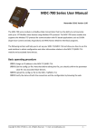
Operating diagram (Brief programming)
Power Factor Controller BR6000-HYBRID (V4.0)
- 25 -
SWITCH. POWER
[100/100] kvar
16
TEST ATTEMT
[ 10 ]
17
TEST TIME
[ 10 ]
18 ASCII TRANSM.TIME
[ 10 ] sec.
1 PASSWORD ????
[ 2244 ]
EXPERT-MODE 2
Activation / Deactivation
of the following
error- messages is
possible with next steps
[ YES/NO ]:
- MEAS.VOLTAGE ?
- OVERVOLTAGE
- OVER COMPENSAT.
- UNDERCOMPENSAT.
- OVERTEMPERATURE
- OVERCURRENT
- UNDERVOLTAGE
- UNDERCURRENT
- MODBUS ERROR
- MMI - ERROR
- REMOTE MODBUS
- CURRENT < ?
- OVERLOAD EQUIP
- C-DEFECT
- CURRENT > 0
- EXTERNAL ERROR
ERROR ME.RELAY
[ 60 ] sec.