1
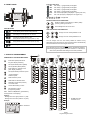
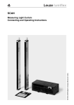
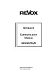
Thank you for choosing a NIVELCO instrument. We are sure that you will be satisfied throughout its use. 1. APPLICATION The UNICONT PMM-300 series is a universal display and controller. It can also be used as (one or two channel) display and limit-switch depending on the configuration of the instrument. For the complete range of the models, technical data and programming in detail see the INSTALLATION AND PROGRAMMING MANUAL. The aim of this User’s Manual is to give a concise guideline for applications of the UNICONT PMM as a process display and limit switch. 2. REAR PANELS 6 7 6 UT I out2 21 22 23 RS485 18 19 20 14 15 16 17 AL3 8 9 IN2 24 25 26 AL4 C TRD C1/AL1 C2/AL2 AL3 3 4 1 5 6 7 2 8 9 UT I out2 21 22 23 RS485 18 19 20 14 15 16 17 AC/DC 1 2 MAINS 7 USER’S MANUAL for applications as display and limit switch valid from software version (indicated at S.PrG) 202 and higher IN2 24 25 26 AL4 C TRD C1/AL1 C2/AL2 AC/DC 9 10 11 12 13 I out1 CJ1 IN1 8 3 4 3 1 2 MAINS 5 1 Rear panel for relay output 4 5 6 SSR 7 9 10 11 12 13 I out1 CJ1 IN1 8 SSR 2 3 4 5 Rear panel for SSR driver output 1 MAINS: Power supply 2 C1/AL1: Control or alarm output from relay 1 3 C2/AL2: Control or alarm output from relay 2 4 Iout1: Analogue current output 1 (proportional to IN1) 5 IN1: Universal input 1 6 AL3-AL4: Contacts (output) of alarm relay 3 and 4 7 RS485: Connector for RS485 interface 8 UT: Transmitter power supply 9 Iout2: Analogue current output 2 (proportional to IN2) 10 IN2: Universal input 2 Manufacturer: Nivelco Process Control Ltd. H-1043 Budapest, Dugonics u. 11. Phone: (36-1) 369-7575 Fax: (36-1) 369-8585 E-mail: [email protected] http://www.nivelco.hu 3. WIRING EXAMPLES Use wire of 0,5…2,5 mm2 for wiring. Voltage input Power supply 1 11 CJ1 2 12 IN1 0/4-20 mA input 13 11 CJ1 12 IN1 0/4-20 mA input 13 24 25 IN2 26 4. ACCESSORIES 1 1 2 1 1 MAINS 2A Cat.“B” ~ + Relay output 1 3 4 RS485 output 18 19 + + Relay output 2 5 6 7 0/4-20 mA output 20 C 9 10 14 8 + 22 UT 23 Iout2 + SSR1 driver output 0/4-20 mA output 23 3 Rt max.600 ohm Rt max.600 ohm SSR2 driver output 6 7 + Power supply for and signal from three wire transmitter 13 + 21 + 22 UT 23 Iout2 + 11 CJ1 12 IN1 13 + Transmitter Transmitter + 4-20 mA 17 4 + + Iout2 12 IN1 16 1 set 1 set Iout 1 11 CJ1 10 ohm Relay output 4 15 Power supply for and signal from two wire transmitter 21 + Relay output 3 22 + 10 ohm 10 ohm + + 0/4-20 mA 10 ohm Installation and Programming Manual User’s Manual Mounting brackets KTY83 for cold junction compensation Resistor for shunting the input with models configured for current input 10 Ohm MR-25, 1%, 0,25W (2 pcs with models with 2 inputs) Plug-in terminal box Measurement stickers 5. PUTTING INTO OPERATION The Steps of putting into operation are: - wiring - switching on the instrument - setting Factory Default (if necessary) The PMM is delivered with (temperature control oriented) Factory Default A. Therefore you have to change over to Factory Default B (See Triple Push-Button Operation) - changing parameters and Electronic Dip Switch (EDS) position (if necessary) Programming will be carried out by the pushbuttons on the front panel (see Point 6.) The programming flow chart and the Menu/Submenu points are shown in Point 7. The Submenu points with grey background are not used in applications as indicator and limitswitch. - With instruments with one input only, the lower (green) row will not be used as display but only for entering the values to be programmed. Indicators LED status 3 AL1: “ON”: Relay 1. (programmed) is energised 6. FRONT PANEL 12 11 1 2 3 4 13 10 1 C “ON”: Relay 2. (programmed) is energised 5 AL3: “ON”: Relay 3. (programmed) is energised 6 AL4: “ON”: Relay 4. (programmed) is energised 8 SV2: “ON”: Second input (IN2) is displayed in green (lower row) 11 PV: “ON”: First input (IN1) is displayed in red (upper row) AT 2 14 PV 1 15 2 17 SV1 AL 5 4 AL2: 3 2 1 7 9 10 12 not applicable SV2 6 4 DOUBLE PUSH-BUTTON OPERATION: 8 16 7 9 + PE Enable or disable of programming of Menu (Table) points by pressing over 25 sec. + Acknowledgement of Er10 and Er11 PUSH-BUTTONS 13 - PE Enter Programming Mode Menus/Submenus Confirm flashing values and EDS settings (ENTER) 14 - Exit Menus/Submenus Acknowledge error messages: Er4, Er5, Er6, Er7 15 - Scrolling Menu/Submenu points Increasing the displayed “flashing” value Setting the EDS switches to the upper position (1= ON) 16 - Decreasing the displayed flashing value Setting the EDS switches to the lower position (0= OFF) 17 - Resetting the latched alarms after repeated power-up TRIPLE PUSH-BUTTON OPERATION: P E + + Change over from Factory Default A to B + + Change over from Factory Default B to A You can change over from one Factory Default to another one by disconnecting the instrument first. Push the three buttons simultaneously and at the same time reconnect it again to the main. Note: By changing over from one Default Program to another will represent reset of the programming performed by the customer i.e. it will result in return to the parameters and settings of the Factory Defaults. 7. STEPS OF PROGRAMMING FUNCTION OF THE PUSH BUTTONS: P E Enter Menu (tables) left side of the green display is flashing Scroll (downstream) Menu (tables) Scroll (upstream) Menu (tables) P E Enter Submenu, right side of the green display is flashing Scroll (downstream) Submenu points Scroll (upstream) Submenu points P E Select Submenu points Select EDS or decrease value Set EDS (to upper/lower position) or increase value P E Confirm EDS setting or value Exit Submenu or Menu (Programming Mode) EDS: Electronic Dip Switch: (symbolised by 8 red light bars on the display) Settings: - Red light bar in the upper position=”1” (ON) - Red light bar in the lower position=”0” (OFF) * ALARM relays are numbered 1 to 4. Example: EDS 00111010 Table 1. Programming flow-chart 8. UNICONT PMM AS ONE-CHANNEL DISPLAY AND LIMIT-SWITCH 8.1 SETTING FACTORY DEFAULT AND PROGRAMMING The instrument will be delivered with Factory Default A. The active Factory Default can be changed over by triple push-button operation and checked in the Submenu point C.in1 (if you can be sure that the Factory Default settings and parameters prevail). C.in.1 xxx01110 xxx11010 Factory Default “A” – Process control oriented “B” – Process indicator with limit switch (4-20 mA input) Note: “X” means that the position of EDS is irrelevant concerning Factory Default. PARAMETERS OF FACTORY DEFAULT B: Denomination Input Position of the decimal point Scaling Operation mode AL1 alarm relay operation AL1 energised over the min value AL2 alarm relay operation AL2 energised over the min value Current output Output value assigned to the minimum input value Output value assigned to the maximum input value Operation of the buzzer Filtering of the input signal Function/Value 4-20mA 999.9 4mA=0,0% 20mA=100,0% Display, 1 input Energised under the lower alarm value 10% Energised over the upper alarm value 90% 4-20mA proportional to the current input 0% 100% in line with AL2 medium EDS/Parameter C.in1 : 00111010 C.i1L : 0.0 C.i1H : 100.0 d.Cnt : 00000001 d.AL1 : 00000001 S.A1 : 10.0 d.AL2 : 10000001 S.A2 = 90.0 C.out : 00001000 C.o1L : 0.0 * C.o1H : 100.0 * d.HSt : 01010000 C.FLt : 00110000 * This setting means that with input 4-20 mA the output will also be 4-20 mA, practically the input will be “retransmitted”. 8.2 CHANGING PARAMETERS OF FACTORY DEFAULT: - Set % value of energising relay AL1 at Submenu point S.A1 - Set % value of energising relay AL2 at Submenu point S.A2 -SETTING HYSTERESIS OF RELAY AL1 Set position of hysteresis (e.g. control of filling) at Submenu point d.AHS: (default parameter: 00000001) Set value of hysteresis at Submenu point d.A1h e.g. 5%, d.A1h=5.0 - SETTING HYSTERESIS OF RELAY AL2 Set position of hysteresis (e.g. control of emptying) at Submenu point d.AHS: (default parameter: 00000000) Set value of hysteresis at Submenu point d.A2h e.g. 5%, d.A2h=5.0 - SETTING BUZZER: At Submenu point d-HSt. (default setting:00000000, out of work) 8.3 SCALING Assign values (e.g. level in meter or % to be displayed) to the input signals - Assign minimum value to the minimum input signal at C.i1L - Assign maximum value to the maximum input signal at C.i1H The displayed value will be proportional to the input signal. For example: Input signal min: 4 mA C.i1L=100.0 Input signal max: 20 mA C.i1H=900.0 Is the input signal IN1=12 mA, the value of 500.0 will be displayed. Note: Should the scaling be changed, the energising values of the ALARM relays have to be modified. 8.4 LINEARISATION Linearisation will be needed if the relation between the measured value and the displayed value is not linear. This non-linear function can be approached by a series of data-pairs. This makes possible for example to display the volume of the medium in a horizontal cylindrical tank by measuring the level. The UNICONT PM-33_ and the PM-34_ can perform a linearisation of 32 data-pairs. - After setting C.uSr the data-pairs are to be entered at the Submenu points I.t01 and O.t01. The measured values and values to be displayed have to be entered at Submenu points I.txx (in the measurement units of the input) and Submenu points O.txx (in the measurement units of the output) respectively. For example should the value at the Submenu point It01 be 15 and the value at the Submenu point O.t01 be 18, that means that with the input signal reaching 15 the value of 18 will be displayed. The 32 point-pairs can be entered in optional order with the constraint that increasing values of I.txx should come with increasing values of O.txx. 9. UNICONT PMM-300 AS TWO-CHANNEL DISPLAY AND LIMIT-SWITCH The UNICONT PMM-32_ and PMM-34_ are configured for applications with two-channel display and limit-switch. 9.1 PROGRAMMING: To programme the second channel you have to take the same steps as described under 8.2. The setting of the decimal point will also be valid for the second channel. (See below the steps with parameters of the Factory Default B.) - Selection of the input signal IN2 (4-20mA): C.in2: 00011010 - Scaling of the input signal IN2 4mA C.i2L: 0.0% 20mA C.i2H: 100.0% - Display IN2 input signal in the bottom row set at d.Cnt: 00010001 - Alarm relay operation AL3: energised under the lower limit of IN2 set at d.AL3: 10000011 - Set energising value of relay AL3 (10%) at Submenu point S.A3:10.0 - Alarm relay operation AL4 energised above the upper limit of IN2, set at d.AL4: 10000011 - set energising value of relay AL4 (90%) at Submenu point S.A4:90.0 9.2 ARITHMETIC FUNCTION Take following steps to make use of differential function - Scale display of input signals IN1 and IN2. - The enabling and the selection of the arithmetic function (difference, summarise or average) will be set at submenu point C.nAt. C.nAt SETTING ARITHMETIC FUNCTIONS EDS Remark No arithmetic function 10000xxx Summarising active, result PV displayed in the upper row PV=IN1+IN2 11000xxx Summarising active, result PV2 not displayed, saved and readable at S.in2 PV2=IN1+IN2 100x0xxx IN1 with positive (+) sign PV=IN1+IN2 101x0xxx IN1 with negative (-) sign PV= - IN1+IN2 10x00xxx IN2 with positive (+) sign PV=IN1+IN2 10x10xxx IN2 with negative (-) sign 10001xxx Providing average PV=IN1-IN2 PV=(IN1+IN2) / 2 Note: “X” means that the position of EDS is irrelevant concerning the arithmetic functions. 9.3 ROUNDING: Rounding may be necessary in applications where due to the technology process the last digit displayed is fluctuating (waves on the surface of the liquid) that has to be eliminated. Rounding, set by the last three digits of the submenu point C.nAt will be performed according to the general rules of the rounding. C.nAt EDS Description xxxxx001 Rounding the last digit to an even number xxxxx010 Rounding the last digit to 0 or 5 xxxxx011 Rounding the last digit to 0 xxxxx100 Rounding the last 2 digits to 20-40-60-80 xxxxx101 Rounding the last 2 digits to a number dividable by 25 xxxxx110 Rounding the last 2 digits to a number dividable by 50 xxxxx111 Rounding the last 2 digits to 00 Steps of linearisation: - The analogue signal arriving on IN1 has to be scaled. (See point 8.3) - The enabling of linearisation and the modifiable analogue signal will be set at Submenu point C.uSr. Description 00000xxx Remark Not depending on the position of the decimal point l Note: “X” means that the position of EDS is irrelevant concerning the rounding. 10. SETS OF SELECTIONS 11. DISABLING FUNCTIONS C.in1 Selection of the input signal, setting decimal point The modifications of some parameters can be disabled by the use of an access code or at the Submenu point d.nni or by push-buttons on the front panel. EDS Range 00000000 00100000 01000000 01100000 00011001 00011010 00011100 00011101 No decimal point 999.9 99.99 9.999 0-20.0 mA 4-20.0 mA 0-100.0 mV 0-500.0 mV a, Disabling by access code Modifications of the Submenu points under the Definition Table and the Calibration Table can be disabled by the access code (the Submenu points under the Parameter Table and the Standard Table can be accessed). There is no access code given in the Factory Default. In the Submenu Point d.Pas (displaying 0) any four-digit access code chosen between 0001 and 8091 can be entered. Instruments with access code will display at d.Pas the number of 9999. After entering the correct access code it can be overwritten (giving either a new four-digit number or 0000 for erasing the access code). Note: In case of access code forgotten or lost, make use of the general reset by repeated Triple Push-Button operation. C.in2 Selection of the input signal (second channel) EDS Range 00011001 00011010 00011100 00011101 0-20.0 mA 4-20.0 mA 0-100.0 mV 0-500.0 mV b, Disabling at Submenu point d.nni: d. AL* Alarmrelays: function selection EDS 00000000 1xx00001 0xx00001 1xx01001 0xx01001 Description No alarm function HIGH Alarm (Relay: NO) Alarm is triggered if the IN1 input signal exceeds upper limit value LOW Alarm (Relay: NC) Alarm is triggered if the IN1 input signal exceeds lower limit value HIGH Alarm (Relay: NC) Alarm relay is triggered if PV value exceeds the upper limit of the (SV) setpoint with a specified (X) value AL=SV + X LOW Alarm (Relay: NO) Alarm relay is triggered if PV value exceeds the lower limit of the (SV) setpoint with a specified (X) value AL=SV -X xxxx1xxx xxxxx1xx In case of entering incorrect values or operation failure an error code will be displayed on the SV display. Error message Description Buzzer is disabled Buzzer operates simultaneously with AL1 Buzzer operates simultaneously with AL2 Buzzer operates simultaneously with AL3 Buzzer operates simultaneously with AL4 00000001 Description Scheme AL1 hysteresis is lower asymmetrical (Filling control) AL1 hysteresis is upper asymmetrical (Emptying control) 00000010 AL1 hysteresis is symmetrical 00000000 AL2 hysteresis is lower asymmetrical (Filling control) 00000100 AL2 hysteresis is upper asymmetrical (Emptying control) AL AL 00001000 AL2 hysteresis is symmetrical 00000000 AL3 hysteresis is lower asymmetrical (Filling control) AL Value entered (e.g. SV) is incorrect :outside of the range Er 1 will be on display for 3 seconds Er 4 Configuration error Acknowledge with key Er 5 Mains power failure Acknowledge with key Er 6 Unauthorised setting of Setpoint Acknowledge with See Submenu point “d.nni” key Er 7 Program deleted: Re-programming is required Acknowledge with key Er 10 Failure at the input, inverse connecting Acknowledge with + keys Er 11 Connection to sensor is broken Acknowledge with + keys AL3 hysteresis is upper asymmetrical (Emptying control) 00100000 AL3 hysteresis is symmetrical 00000000 AL4 hysteresis is lower asymmetrical (Filling control) 01000000 AL4 hysteresis is upper asymmetrical (Emptying control) 10000000 AL4 hysteresis is symmetrical PV Er 11 will only be displayed in RUN mode and with manual control enabled. PV C.FLt Setting the filtering of In1 and In2 input signals PV AL 00110000 Error messages Er10 and Er11 can also be acknowledged by switching off and on the power supply. Should the failure not be repaired, the error message will reappear after 2 minutes on the PV display. EDS AL PV 00000000 00000000 10000000 AL AL PV PV AL PV AL AL Remark PV PV AL Description Er 1 d.AHS Hysteresis type alarms relays EDS Factory Default 12. ERROR MESSAGES “X” means that the position is irrelevant concerning the operation of the buzzer. 00000000 Remark c, Disabling by push-button (See Double Push-Button Operation) Disabling access to the Menupoint Definition (table) by simultaneous pressing of the push-buttons and P E over 25 sec. Repeated Double Push-Button operation will release disabling. d.HSt Internal buzzer (acoustic alarm) x1xxxxxx 0100xxxx 0101xxxx 1100xxxx 1101xxxx Description Alarm relays disabled Display values settable by digits (spinning wheel) Display values settable in sequence (by scrolling) After power supply failure the instrument will be switched out with Er5. xxxx0xxx - Serial number of the alarm relays AL 1,2,3,4,5,6 depending on the configuration - “X” means that the position is irrelevant concerning the alarm relays EDS EDS xxxxxxx1 00110000 01111111 Description * Serial number of the alarm relays (AL1, AL2, AL3 and AL4), depending on the ordered configuration. PV PV AL PV Note: The hysteresis of the relays AL5 and AL6 is always symmetric. Set hysteresis at S.A*h. Remark No filtering A/D conversion optimised to mains for 50 Hz A/D conversion optimised to mains for 60 Hz Recommended value The strongest (longest) filtering time (approx. 50-70 sec) NIVELCO Process Control Ltd. PM30G0A2 05.05.2000