1
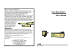
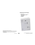
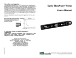
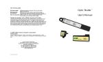
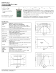
The coffee mug logger test
Voltage (V)
You can make a simple battery using
coffee, a stainless steel spoon and a little
bit of aluminum foil. Connect the
aluminum foil to the black lead from
your HOBO Volt and the yellow lead to
the spoon. Place both the foil and the
spoon in the coffee, making sure that
the foil and the spoon do not touch.
Your coffee is acidic enough to make a
weak battery. The plot at the right
shows the voltage output of the
battery with time. We attribute the initial drop to the
coffee’s cooling.
Why does it rise with time,
and what causes the
oscillation? If you know the
answers, please tell us.
NSET
ONSE
HOBO® VOLT
0.90
0.85
User’s Manual
0.80
0.75
0.70
0.65
0.60
08:00
23Feb95 08:00
09:00
10:00
Coffee …
11:00
S/N 429
Battery Instructions
In normal usage the 3.6 volt HOBO battery is expected to last two years, although it is suggested that you change the battery every year. To change the battery, remove the logger’s cover.
Remove the old battery by pulling it straight away from the board. To remove the high internal
resistance that builds up when this kind of battery is not in use, short the new battery for one
second by touching the leads with a paper clip before installing it. When the battery first makes
contact the status LED on the board should blink brightly five times. If it does not, remove the
battery, wait ten seconds and try again. Finally, place the cover back on the HOBO Volt logger,
lining it up so that the LED shows through the intended spot on the label.
© 1996-1999, Onset Computer Corporation
Trademarks
Onset®, HOBO®, StowAway®, StowAway®TidbiT®, Optic Shuttle™, Optic Base
Station™, Optic Coupler™, TidbiT® Coupler™, and BoxCar® are trademarks of
Onset Computer Corporation.
Onset Computer Corporation
470 MacArthur Blvd., Bourne, MA 02532
Mailing: PO Box 3450, Pocasset, MA 02559-3450
8:00 AM to 5:00 PM EST
Tel:1-800-LOGGERS (1-800-564-4377)
Tel: 508-759-9500, Fax: 508-759-9100
E-mail: [email protected]
Internet: http://www.onsetcomp.com
D-1584-C MAN-HV
Thank you for purchasing a HOBO® Voltage logger. The HOBO Volt was designed as
a general purpose voltage logger. Its accepts inputs ranging from 0 volts to 2.5 DC volts.
Warning
Do not apply a signal to the A-D input that is more than 0.2 volts lower than ground, or
0.2 volts higher that the battery supply (nominally 3.5 volts).
Timing Diagram
Calibration
The HOBO Volt logger has no calibration adjustments. The accuracy is guaranteed by
using precision parts. To check for possible part failures or assembly problems, each
HOBO Volt logger is tested for accuracy at eight different voltages to verify that they are
within specifications.
Accuracy
±10 mV ± 0.5% of reading. NOTE: The HOBO Volt logger cannot store the value 0 volts,
and substitutes 10 mV instead.
Connection points
The HOBO Volt has four connections, starting near the edge of the box: A-D input (0 to
2.5 volts, analog input); Sense line (active high, digital output); Battery supply (3.5 volt
nominal, output) and Ground (output).
Connect the HOBO Volt logger to the host computer using the appropriate interface cable
(CABLE-PC-3.5 for a PC and CABLE-MAC-HOBO for a Macintosh). When connecting the
3.5 mm communications cable to your HOBO Volt logger make sure that it is pushed
completely into the connector! You will now be able to communicate with the HOBO Volt
logger using the host software. (See the software user’s manual for launch details). Recommended software: BoxCar® 3.6+ or any version of BoxCar® Pro. At the end of the deployment, reconnect your logger to the host computer for readout. The HOBO Volt logger
communicates at 1200 baud. Its cleverly optimized software allows a full 2K off-load in
only twenty seconds.
Operating environment
Time accuracy
At room temperature, the logger’s idea of time can vary
from the actual time by as much as one hour per year
(100 ppm). There is an additional temperature effect
shown in Plot A.
The input is active for a fifteen millisecond period
during each measurement. The actual A-D reading
occurs two milliseconds after the start of this period
(see timing diagram at the right).
15mS
Sense Line
Input characteristics
Input Sample
2mS
2mS
±0.1 µA leakage max. while disconnected, ±0.4 µA
while connected.
Note: The sense line and analog input lines have 100K resistors in series with them to
help protect them from out-of-range inputs.
Battery: for unusual applications only
Launch and recovery
Your HOBO Volt logger will operate correctly within the
temperature range -40°C to +75°C. Do not expose to an
environment where condensation will form on the logger.
Condensation will cause corrosion. The logger’s accuracy
is specified within this range as well. Continuous exposure to temperatures above +45°C will reduce the HOBO
Volt logger’s battery life.
Timing
The battery output line is not normally used. It connects directly to the HOBO Volt
logger’s internal 3.5 volt battery which has a capacity of 370 mAHr. Drawing current from
this line will reduce the life of the HOBO Volt logger’s battery.
The sense output line (not normally used)
This output line is high (about 3.5 volts) during the fifteen millisecond time that the
HOBO Volt takes a measurement, and low at all other times. This output can be used to
turn on power to an external sensor only during a measurement, thereby minimizing the
sensor’s current drain. The external electonics needed to turn on power to the sensor
depends on the application.
An example using the Sense line
Plot A Graph 1093
Timebase dependence
Reed switches close in the presence of a strong magnetic field. A
HOBO Volt can be used to monitor the switch closure using the
circuit shown at right. When the switch is open, the input signal
will follow the sense line voltage. When the switch is closed, it will
stay at ground level. The 100K resistor is not really needed since
there is one on the inside of the HOBO Volt logger. The average
current drain of the HOBO Volt is about 20 µA and the sense line is
only high for fifteen milliseconds during each measurement cycle.
At a half second interval the average current drain due to the
switch sensing circuit is (3.5/100,000)*(15/500) or about 1 µA, and
correspondingly lower for longer intervals.
Sense
100K
Input
Reed
Switch
Ground