1
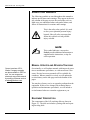
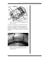
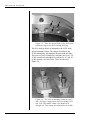
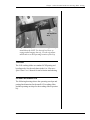
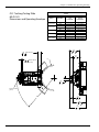
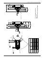
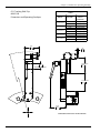
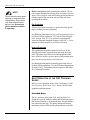
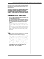
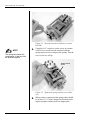
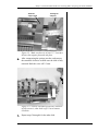
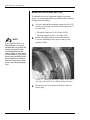
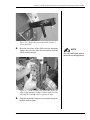
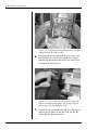
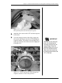
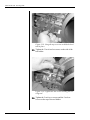
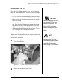
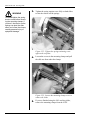
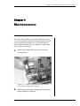
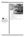
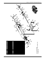
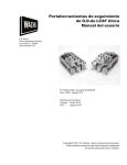
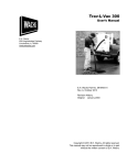
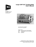
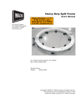
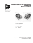
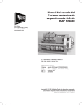
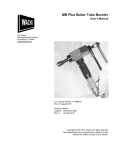
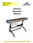
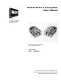
Small LCSF O.D. Tracking Slide
User’s Manual
E.H. Wachs
600 Knightsbridge Parkway
Lincolnshire, IL 60069
www.ehwachs.com
E.H. Wachs Part No. 60-MAN-06
Rev. 2-0811, August 2011
Revision History:
Original January 2010
Rev. 1
August 2010
Copyright © 2011 E.H. Wachs. All rights reserved.
This manual may not be reproduced in whole or in part
without the written consent of E.H. Wachs.
Small LCSF O.D. Tracking Slide
Part No. 60-MAN-06, Rev. 2-0811
E.H. Wachs
Table of Contents
Table of Contents
Chapter 1: About the Small LCSF O.D. Tracking Slides . . . . . . . . . . . . . . . . . . . . . . . . . . . . 1
Purpose of This Manual . . . . . . . . . . . . . . . . . . . . . . . . . . . . . . . . . . . . . . . . . . . . . . . . . . . . . . . . . 1
How to Use The Manual . . . . . . . . . . . . . . . . . . . . . . . . . . . . . . . . . . . . . . . . . . . . . . . . . . . . . . . . 1
Symbols and Warnings . . . . . . . . . . . . . . . . . . . . . . . . . . . . . . . . . . . . . . . . . . . . . . . . . . . . . . . . . 2
Manual Updates and Revision Tracking . . . . . . . . . . . . . . . . . . . . . . . . . . . . . . . . . . . . . . . . . . . . 2
Equipment Description . . . . . . . . . . . . . . . . . . . . . . . . . . . . . . . . . . . . . . . . . . . . . . . . . . . . . . . . . 2
Tooling . . . . . . . . . . . . . . . . . . . . . . . . . . . . . . . . . . . . . . . . . . . . . . . . . . . . . . . . . . . . . . . . . . . . . . 5
Operating Envelope . . . . . . . . . . . . . . . . . . . . . . . . . . . . . . . . . . . . . . . . . . . . . . . . . . . . . . . . . . . . 5
Chapter 2: Safety . . . . . . . . . . . . . . . . . . . . . . . . . . . . . . . . . . . . . . . . . . . . . . . . . . . . . . . . . . . . . 9
Safe Operating Guidelines . . . . . . . . . . . . . . . . . . . . . . . . . . . . . . . . . . . . . . . . . . . . . . . . . . . . . . . 9
Safe Operating Environment . . . . . . . . . . . . . . . . . . . . . . . . . . . . . . . . . . . . . . . . . . . . . . . . . 10
Operating and Maintenance Safety . . . . . . . . . . . . . . . . . . . . . . . . . . . . . . . . . . . . . . . . . . . . 10
Safety Alerts in This Manual . . . . . . . . . . . . . . . . . . . . . . . . . . . . . . . . . . . . . . . . . . . . . . . . . 11
Protective Equipment Requirements . . . . . . . . . . . . . . . . . . . . . . . . . . . . . . . . . . . . . . . . . . . 11
Protective Clothing . . . . . . . . . . . . . . . . . . . . . . . . . . . . . . . . . . . . . . . . . . . . . . . . . . . . . 11
Eye Protection . . . . . . . . . . . . . . . . . . . . . . . . . . . . . . . . . . . . . . . . . . . . . . . . . . . . . . . . . 12
Hearing Protection . . . . . . . . . . . . . . . . . . . . . . . . . . . . . . . . . . . . . . . . . . . . . . . . . . . . . . 12
Safe Operation of the O.D. Tracking Slides . . . . . . . . . . . . . . . . . . . . . . . . . . . . . . . . . . . . . . . . 12
Intended Uses . . . . . . . . . . . . . . . . . . . . . . . . . . . . . . . . . . . . . . . . . . . . . . . . . . . . . . . . . . . . . 12
Proper Use of the O.D. Tracking Slides . . . . . . . . . . . . . . . . . . . . . . . . . . . . . . . . . . . . . . . . 13
Misuse . . . . . . . . . . . . . . . . . . . . . . . . . . . . . . . . . . . . . . . . . . . . . . . . . . . . . . . . . . . . . . . 13
Potential Hazards . . . . . . . . . . . . . . . . . . . . . . . . . . . . . . . . . . . . . . . . . . . . . . . . . . . . . . . . . . 14
O.D. Tracking Slide Safety Features . . . . . . . . . . . . . . . . . . . . . . . . . . . . . . . . . . . . . . . . . . . 14
Safe Lifting and Handling . . . . . . . . . . . . . . . . . . . . . . . . . . . . . . . . . . . . . . . . . . . . . . . . . . . 14
Safety Labels . . . . . . . . . . . . . . . . . . . . . . . . . . . . . . . . . . . . . . . . . . . . . . . . . . . . . . . . . . . . . . . . 15
Chapter 3: Operating Instructions . . . . . . . . . . . . . . . . . . . . . . . . . . . . . . . . . . . . . . . . . . . . . . 17
Preparing the LCSF and Slides . . . . . . . . . . . . . . . . . . . . . . . . . . . . . . . . . . . . . . . . . . . . . . . . . . 17
Mounting the Slides and Trip . . . . . . . . . . . . . . . . . . . . . . . . . . . . . . . . . . . . . . . . . . . . . . . . . . . 20
Performing the Cut . . . . . . . . . . . . . . . . . . . . . . . . . . . . . . . . . . . . . . . . . . . . . . . . . . . . . . . . . . . . 29
Chapter 4: Maintenance . . . . . . . . . . . . . . . . . . . . . . . . . . . . . . . . . . . . . . . . . . . . . . . . . . . . . . 31
Chapter 5: Parts List and Ordering Information . . . . . . . . . . . . . . . . . . . . . . . . . . . . . . . . . . 33
Ordering Information . . . . . . . . . . . . . . . . . . . . . . . . . . . . . . . . . . . . . . . . . . . . . . . . . . . . . . . . . . 33
Ordering Replacement Parts . . . . . . . . . . . . . . . . . . . . . . . . . . . . . . . . . . . . . . . . . . . . . . . . . 33
Repair Information . . . . . . . . . . . . . . . . . . . . . . . . . . . . . . . . . . . . . . . . . . . . . . . . . . . . . . . . . 33
Warranty Information . . . . . . . . . . . . . . . . . . . . . . . . . . . . . . . . . . . . . . . . . . . . . . . . . . . . . . 34
Return Goods Address . . . . . . . . . . . . . . . . . . . . . . . . . . . . . . . . . . . . . . . . . . . . . . . . . . . . . . 34
Drawings and Parts Lists . . . . . . . . . . . . . . . . . . . . . . . . . . . . . . . . . . . . . . . . . . . . . . . . . . . . . . . 34
E.H. Wachs
Part No. 60-MAN-06, Rev. 2-0811
1
Small LCSF O.D. Tracking Slide
2
Part No. 60-MAN-06, Rev. 2-0811
E.H. Wachs
Chapter 1, About the Small LCSF O.D. Tracking Slides
Chapter 1
About the Small LCSF
O.D. Tracking Slides
In This Chapter
PURPOSE OF THIS MANUAL
This manual explains how to operate and maintain the O.D.
tracking slides for 4”-20” low clearance split frames. It
includes instructions for set-up, operation, and maintenance. It also contains parts lists and diagrams, and troubleshooting instructions to help you order replacement parts
and perform user-serviceable repairs.
PURPOSE OF THIS MANUAL
HOW TO USE THE MANUAL
SYMBOLS AND WARNINGS
MANUAL UPDATES AND
REVISION TRACKING
EQUIPMENT DESCRIPTION
TOOLING
OPERATING ENVELOPE
HOW TO USE THE MANUAL
This manual is organized to help you quickly find the information you need. Each chapter describes a specific topic on
using or maintaining the equipment.
Each page is designed with two columns. This large column
on the inside of the page contains instructions and illustrations. Use these instructions to operate and maintain the
equipment.
Throughout this manual, refer
to this column for warnings,
cautions, and notices with
supplementary information.
The narrower column on the outside contains additional
information such as warnings, special notes, and definitions. Refer to it for safety notes and other information.
E.H. Wachs
Part No. 60-MAN-06, Rev. 2-0811
1
Small LCSF O.D. Tracking Slide
SYMBOLS AND WARNINGS
The following symbols are used throughout this manual to
indicate special notes and warnings. They appear in the outside column of the page, next to the section they refer to.
Make sure you understand what each symbol means, and
follow all instructions for cautions and warnings.
This is the safety alert symbol. It is used
to alert you to potential personal injury
hazards. Obey all safety messages that
follow this symbol to avoid possible
injury or death.
NOTE
This symbol indicates a user notice.
Notices provide additional information to
supplement the instructions, or tips for
easier operation.
MANUAL UPDATES AND REVISION TRACKING
Current versions of E.H.
Wachs Company manuals
are also available in PDF format. You can request an
electronic copy of this manual
by emailing customer service
at [email protected].
Occasionally, we will update manuals with improved operation or maintenance procedures, or with corrections if necessary. Revised accessory manuals will be available for
customers. When a manual is revised, we will update the
revision history on the title page and at the bottom of the
pages.
You may have factory service or upgrades performed on the
equipment. If this service changes any technical data or
operation and maintenance procedures, we will include a
revised manual when we return the equipment to you.
EQUIPMENT DESCRIPTION
The components of the O.D. tracking slide are shown in
Figure 1-1. The slide set includes a parting slide and a parting/beveling slide.
2
Part No. 60-MAN-06, Rev. 2-0811
E.H. Wachs
Chapter 1, About the Small LCSF O.D. Tracking Slides: Equipment Description
Tool cover
plate
Spring tensioning screw
Tool
holder
Starwheel
Tracking
wheel
Guide rod
Tensioning
spring
Base plate
Figure 1-1. The photo shows the components of the
O.D. tracking slide.
Note that special tapped hole are required in the LCSF to
mount the O.D. tracking slides and the tracking slide trip.
See Figure 1-2 and Figure 1-3. Recently manufactured
machines have these holes; if your LCSF does not, contact
the factory at 847-537-8800 to arrange to have your LCSF
modified.
Figure 1-2. There are special holes for the O.D.
tracking slides in the LCSF rotating ring at the slide
mounting locations.
E.H. Wachs
Part No. 60-MAN-06, Rev. 2-0811
3
Small LCSF O.D. Tracking Slide
Figure 1-3. There are special holes in the back of the
stationary ring for the O.D. tracking slide trip.
The O.D. tracking slides are mounted to the LCSF using
special mounting clamps. The clamps are bolted to the
LCSF rotating ring, and tightened down to hold the slides.
There are two sets of clamps for each slide: one for 10”-14”
LCSFs (models 610 through 814), and one for 16” and 20”
LCSFs (models 1016 and 1420). These are shown in
Figure 1-4.
Figure 1-4. Two sizes of mounting clamps are available. The larger clamp on the left is for models 1016
and 1420. The smaller clamp is for models 610
through 814. Two clamps are required for each slide.
4
Part No. 60-MAN-06, Rev. 2-0811
E.H. Wachs
Chapter 1, About the Small LCSF O.D. Tracking Slides: Tooling
Trip
Trip adjustment
knob
Trip lock lever
Figure 1-5. The photo shows the tracking slide trip
installed on the LCSF. Use the trip lock lever to
engage and disengage the trip. Use the trip adjustment knob to set the operating location of the trip.
TOOLING
The O.D. tracking slides use standard LCSF parting and
beveling tools. See the tool charts in the Low Clearance
Split Frame User’s Manual for tool selection and ordering.
OPERATING ENVELOPE
The following drawings shows the operating envelope and
parting line dimension for the small O.D. tracking slides,
and the operating envelope for the tracking slide trip assembly.
E.H. Wachs
Part No. 60-MAN-06, Rev. 2-0811
5
Chapter 1, Introduction: Operating Envelope
O.D. Tracking Parting Slide
60-451-01
Dimensions and Operating Envelope
-TABLEMODEL
POSITION
DIM. "A"
PIPE
DIAMETER
MIN.
MAX.
MIN.
6.63 [168.4]
10.75 [273.1]
6.63 [168.4]
13.94 [354.0]
16.00 [406.3]
13.94 [354.0]
MAX.
MIN.
12.75 [323.9]
8.63 [219.1]
17.00 [431.7]
14.94 [379.4]
MAX.
MIN.
MAX.
MIN.
MAX.
14.00 [355.6]
10.75 [273.1]
16.00 [406.4]
17.62 [447.6]
16.00 [406.3]
18.62 [473.0]
14.00 [355.6]
20.00 [508.0]
17.62 [447.6]
20.62 [523.8]
LCSF 610/3
LCSF 612/3
LCSF 814/3
LCSF 1016/3
LCSF 1420/3
DIM. "B"
RADIAL
CLEARANCE
4.17
105.9
1.66 SLIDE TRAVEL
42.2
2.73
69.2
.50
SPRING TRAVEL
12.7
(MAX. SHOWN)
"A"
.99
25.1
.00313 PER TRIP
[.0794]
.13
3.3
"B"
5.93
150.6
7.37
187.3
E.H. Wachs
60-MAN-06
6
E.H. Wachs
60-MAN-06
MIN.
MAX.
MIN.
MAX.
LCSF 612/3
LCSF 814/3
LCSF 1420/3
LCSF 1016/3
MIN.
MAX.
LCSF 610/3
MAX.
MIN.
MAX.
MIN.
POSITION
MODEL
.00313 PER TRIP
[.0794]
.50
SPRING TRAVEL
12.7
(MAX. SHOWN)
13.94 [354.0]
16.00 [406.3]
13.94 [354.0]
17.00 [431.7]
14.94 [379.4]
17.62 [447.6]
16.00 [406.3]
18.62 [473.0]
17.62 [447.6]
20.62 [523.8]
6.63 [168.4]
12.75 [323.9]
8.63 [219.1]
14.00 [355.6]
10.75 [273.1]
16.00 [406.4]
14.00 [355.6]
20.00 [508.0]
DIM. "B"
RADIAL
CLEARANCE
"B"
10.75 [273.1]
6.63 [168.4]
DIM. "A"
PIPE
DIAMETER
-TABLE-
1.66 SLIDE TRAVEL
42.2
"A"
.51
13.0
.99
25.1
4.22
107.1
5.99
152.2
7.42
188.5
.12
3.0
5.26
133.6
.85
21.6
2.79
70.8
2.06
52.2
4.72
119.8
1.60
40.6
2.06
52.2
3.20
81.4
5.26
133.6
O.D. Tracking Beveling Slide
60-451-02
Dimensions and Operating Envelope
COVER, OUTSIDE BEVEL TOOL
60-1051-00
.63
16.0
7.92
201.2
Chapter 1, Introduction: Operating Envelope
7
Chapter 1, Introduction: Operating Envelope
O.D. Tracking Slide Trip
60-451-03
Dimensions and Operating Envelope
-TABLEMODEL
LCSF 610/3
LCSF 612/3
LCSF 814/3
LCSF 1016/3
LCSF 1420/3
3.77
95.8
"A"
POSITION
DIM. "A"
RADIAL
CLEARANCE
MIN.
16.55 [420.4]
MAX.
17.80 [452.2]
17.60 [447.1]
18.85 [478.9]
18.22 [462.7]
19.47 [494.5]
19.34 [491.2]
20.59 [523.0]
21.20 [538.5]
22.45 [570.2]
MIN.
MAX.
MIN.
MAX.
MIN.
MAX.
MIN.
MAX.
.19
4.8
1.25
31.8
DISENGAGE TRAVEL
3.88 MAX
98.5
4.59 MAX
116.5
4.04
102.6
DIMENSIONS IN BRACKETS ARE MILLIMETERS
E.H. Wachs
60-MAN-06
8
Chapter 2, About the Small LCSF O.D. Tracking Slides
Chapter 2
Safety
In This Chapter
E.H. Wachs takes great pride in designing and manufacturing safe, high-quality products. We make user safety a top
priority in the design of all our products.
Read this chapter carefully before operating the LCSF with
the O.D. tracking slides. It contains important safety
instructions and recommendations.
SAFE OPERATING GUIDELINES
SAFE OPERATION OF THE O.D.
TRACKING SLIDES
SAFETY LABELS
FULL SAFETY INSTRUCTIONS AND GUIDELINES
ARE IN THE MANUAL FOR YOUR LOW CLEARANCE SPLIT FRAME MACHINE. Make sure you read
and understand all safety information in the LCSF manual.
SAFE OPERATING GUIDELINES
Follow these guidelines for safe operation of all E.H.
Wachs equipment.
•
•
•
READ THE OPERATING MANUAL. Make sure you under-
stand all setup and operating instructions before you
begin. Keep this manual with the machine.
INSPECT MACHINE AND ACCESSORIES BEFORE USE. Before
starting the machine, look for loose bolts or nuts, leaking lubricant, rusted components, and any other physical conditions that may affect operation. Properly
maintaining the machine can greatly decrease the
chances for injury.
ALWAYS READ STICKERS AND LABELS. Make sure all labels
and stickers are in place, clearly legible, and in good
E.H. Wachs
Part No. 60-MAN-06, Rev. 2-0811
Look for this symbol throughout the
manual. It indicates
a personal injury
hazard.
9
Small LCSF O.D. Tracking Slide
•
•
•
condition. Refer to “Safety Labels” later in this chapter
for label locations on the machine. Replace any damaged or missing safety labels; see the ordering information at the end of this manual.
KEEP CLEAR OF MOVING PARTS. Keep hands, arms, and
fingers clear of all rotating or moving parts. Always turn
the machine off and disconnect the power source before
doing any adjustments or service.
SECURE LOOSE CLOTHING AND JEWELRY. Secure or
remove loose-fitting clothing and jewelry, and securely
bind long hair, to prevent them from getting caught in
moving parts of the machine.
FOLLOW SAFE PROCEDURES FOR HANDLING LUBRICANTS.
Refer to the manufacturer’s instructions and the Material Safety Data Sheets.
Safe Operating Environment
•
•
•
Do not use this equipment in a potentially explosive
atmosphere. Fire or explosion could result, with the risk
of serious injury or death.
Provide adequate lighting to use the equipment, in
accordance with worksite or local regulations.
KEEP WORK AREA CLEAR. Keep all clutter and nonessential materials out of the work area. Only people directly
involved with the work being performed should have
access to the area.
Operating and Maintenance Safety
•
•
•
•
10
This equipment is to be operated and maintained only
by qualified, trained personnel.
Make sure the equipment is stable when attached to the
workpiece for the operation. Ensuring stability of the
installed tool is the responsibility of the operator.
Make sure the workpiece is supported adequately for
installation of the equipment. This includes supporting
any workpiece “fall-off” section when severing the
workpiece. Ensuring support of the workpiece is the
responsibility of the operator.
Tooling on any cutting equipment—including lathe
tools, saw blades, milling tools, etc.—may get very hot.
Do not touch tooling until you have made sure it is cool
enough to handle.
Part No. 60-MAN-06, Rev. 2-0811
E.H. Wachs
Chapter 2, About the Small LCSF O.D. Tracking Slides: Safe Operating Guidelines
•
•
Wear gloves when removing or cleaning up chips and
cutting debris. Chips can be very sharp and cause cuts.
Before performing any service on the equipment, disconnect the power source. Follow all lock-out/tag-out
procedures required at the worksite.
Safety Alerts in This Manual
The following alerts are used throughout this manual to
indicate operator safety hazards. In all cases, these alerts
include a notice describing the hazard and the means to
avoid or reduce risk. Carefully read all safety alerts.
This icon is displayed with any safety alert that indicates a
personal injury hazard.
WARNING
This safety alert, with the personal injury hazard symbol,
indicates a potentially hazardous situation that, if not
avoided, could result in death or serious injury.
CAUTION
This safety alert, with the personal injury hazard symbol,
indicates a potentially hazardous situation that, if not
avoided, could result in minor or moderate injury.
Protective Equipment Requirements
Protective Clothing
Wear safety shoes when operating or servicing the equipment. Serious injury could result from dropping the
machine or its components.
E.H. Wachs
Part No. 60-MAN-06, Rev. 2-0811
11
Small LCSF O.D. Tracking Slide
NOTE
Gloves should be worn when
cleaning up chips and other
cutting debris. Chips can be
very sharp and can cause
serious cuts. Do not wear
gloves when the machine
is operating.
Do not wear gloves while operating the machine. Gloves
can become entangled in moving parts, resulting in serious
injury. Gloves may be worn when setting up the machine or
cleaning up after the operation, but take them off when
operating the machine.
Eye Protection
Always wear impact-resistant eye protection while operating or working near this equipment.
For additional information on eye and face protection, refer
to Federal OSHA regulations, 29 Code of Federal Regulations, Section 1910.133., Eye and Face Protection and
American National Standards Institute, ANSI Z87.1, Occupational and Educational Eye and Face Protection.
Hearing Protection
This equipment can produce noise levels above 80 dB.
Hearing protection is required when operating the equipment. The operation of other tools and equipment in the
area, reflective surfaces, process noises, and resonant structures can increase the noise level in the area.
For additional information on hearing protection, refer to
Federal OSHA regulations, 29 Code of Federal Regulations,
Section 1910.95, Occupational Noise Exposure and ANSI
S12.6 Hearing Protectors.
SAFE OPERATION OF THE O.D. TRACKING
SLIDES
Refer to “Safe Operation of the LCSF” in Chapter 2 of the
Low Clearance Split Frame User’s Manual for full safety
guidelines and instructions.
Intended Uses
The low clearance split frame O.D. tracking slides are
designed to provide uniform cutting and beveling on pipes
that are out of round, or in situations where the split frame is
not centered on the pipe. The spring-tensioned tracking
mechanism allows radial motion (perpendicular to the side
12
Part No. 60-MAN-06, Rev. 2-0811
E.H. Wachs
Chapter 2, About the Small LCSF O.D. Tracking Slides: Safe Operation of the O.D. Tracking Slides
of the pipe) of up to 1/2 inch, keeping the cutting tool on the
pipe at all times and compensating for a maximum 1 inch
out-of-roundness.
Make sure to follow all safety guidelines and procedures
required for machining operations at the work site,
including personal protective equipment (PPE). Do not
use the LCSF in a manner that violates these guidelines.
Proper Use of the O.D. Tracking Slides
•
•
•
•
The LCSF and O.D. tracking slides should only be used
by trained, qualified operators.
The workpiece must be within the operating capacity of
the O.D. tracking slides and LCSF model you are using.
See operating envelope information and drawings in
Chapter 1.
Make sure the operating environment allows you to
mount the machine securely and squarely on the workpiece.
Make sure there is adequate clearance around workpiece
and the LCSF/O.D. tracking slide combination to operate the machine controls as described in the operating
instructions.
Misuse
•
•
•
•
Do not attempt to mount or operate the LCSF and O.D.
tracking slides on non-cylindrical workpieces.
Do not attempt to mount or operate the LCSF and O.D.
tracking slides on any workpiece to which the equipment cannot be securely mounted.
Do not attempt to mount or operate the LCSF and O.D.
tracking slides on any workpiece that is not stable
enough to hold the equipment.
Do not disable any safety feature of theO.D. tracking
slides or LCSF, or remove any safety labeling. Replace
worn or damaged safety labels immediately. (See
“Safety Labels” later in this chapter.)
E.H. Wachs
Part No. 60-MAN-06, Rev. 2-0811
13
Small LCSF O.D. Tracking Slide
Potential Hazards
See the “Potential Hazards” section in Chapter 2 of the
user’s manual for your low clearance split frame machine.
Follow all guidelines for avoiding hazards associated with
operating the machine.
O.D. Tracking Slide Safety Features
The small O.D. tracking slides include a guard to cover the
pinch point between the support plate and the tracking bar
end plate. Do not operate the slides without this guard
installed. If you need to remove the guard for service, make
sure the springs are released, and make sure to re-install the
guard before operation.
Guard
Figure 2-1. The O.D. tracking slides have a guard to
keep fingers out of the pinch point at the end of the
slide.
Safe Lifting and Handling
•
•
14
The small O.D. tracking slides weigh less than 40 lb
each. (Machines or assemblies over 40 lb [18 kg] must
be lifted by two people or a lifting device.)
It is the responsibility of the end user to determine
whether a machine or assembly can be lifted by two or
more people. A lifting device is recommended for
machines or assemblies that cannot be handled easily by
two people.
Part No. 60-MAN-06, Rev. 2-0811
E.H. Wachs
Chapter 2, About the Small LCSF O.D. Tracking Slides: Safety Labels
•
It is not recommended that you lift the LCSF with the
O.D. tracking slides attached. The assembled combination may not be balanced to enable safe lifting.
SAFETY LABELS
The Moving Parts label is attached to the O.D. tracking
slide trip. Do not remove the label. If the label is lost or
damaged, order a replacement label from E.H. Wachs; see
ordering instructions in Chapter 5.
Figure 2-2. The Moving Parts warning label is on the
trip assembly (part no. 03-113-04).
E.H. Wachs
Part No. 60-MAN-06, Rev. 2-0811
15
Small LCSF O.D. Tracking Slide
16
Part No. 60-MAN-06, Rev. 2-0811
E.H. Wachs
Chapter 3, About the Small LCSF O.D. Tracking Slides
Chapter 3
Operating
Instructions
Before using the LCSF O.D. tracking slides, you should be
familiar with all LCSF operating and safety procedures.
Refer to the Low Clearance Split Frame User’s Manual.
In This Chapter
PREPARING THE LCSF AND
SLIDES
MOUNTING THE SLIDES AND
TRIP
PREPARING THE LCSF AND SLIDES
PERFORMING THE CUT
The cut line for the O.D. tracking slides is 2.73” (69.3 mm)
above the slide mounting surface on the rotating ring. See
the Operating Envelope drawings in Chapter 1.
1. Mount and center the LCSF according to the instructions in the Low Clearance Split Frame User’s Manual.
2. Remove any trips, slides, or other accessories from
the LCSF.
3. Set the O.D. tracking slides on a workbench or other
stable work surface. Using a 9/16” wrench or socket,
turn the castle nut on the starwheel clockwise to fully
retract the slide.
E.H. Wachs
Part No. 60-MAN-06, Rev. 2-0811
CAUTION
Do not leave other accessories, such as standard trip
assemblies, mounted on the
LCSF when using the O.D.
tracking slide. These accessories may collide with the
tracking slides, causing damage to the equipment.
17
Small LCSF O.D. Tracking Slide
Figure 3-1. Turn the starwheel clockwise to retract
the slide.
NOTE
The springs should be fully
compressed, so that the coils
are pressed together.
4. Using the 9/16” wrench or socket, screw in (counter-
clockwise as viewed from the starwheel end) the
spring tension screw to compress the springs. Turn the
screw as far as it will go.
Spring tension
screw
Figure 3-2. Tighten the spring tension screw all the
way.
5. When you have compressed the springs, there should
be at least 1/2” (13 mm) clearance between the tracking bar end plate and the guide bar support plate.
18
Part No. 60-MAN-06, Rev. 2-0811
E.H. Wachs
Chapter 3, About the Small LCSF O.D. Tracking Slides: Preparing the LCSF and Slides
Guide bar
support plate
Tracking bar
end plate
Figure 3-3. Make sure there is at least 1/2” clearance
between the support plate and end plate.
6. After compressing the springs, turn the castle nut on
the starwheel clockwise to make sure the slide is fully
retracted. Back the screw off 1/2 turn.
Figure 3-4. Turn the starwheel all the way clockwise
to fully retract it, then back it off 1/2 turn counterclockwise.
7. Repeat steps 3 through 6 for the other slide.
E.H. Wachs
Part No. 60-MAN-06, Rev. 2-0811
19
Small LCSF O.D. Tracking Slide
MOUNTING THE SLIDES AND TRIP
To minimize the risk of equipment damage or personal
injury, it is recommended that you install the slides without
tooling in the tool holders.
1. Select the appropriate mounting clamps for the LCSF
model you are using. You will need 4 clamps total—2
for each slide.
NOTE
If you have the LCSF on a
horizontal pipe, it is recommended that you position the
rotating ring with the slide
mounting positions at the
sides (roughly 3 o’clock and 9
o’clock positions). If you have
the mounting positions at the
top and bottom, the slide on
the bottom may fall out while
you are mounting and adjusting it.
2.
• The small clamps are for 10-14 inch LCSFs.
• The large clamps are for 16-20 inch LCSFs.
Install 2 mounting clamps at each slide location.
Leave the mounting screws loose so that you can
install the slides.
Figure 3-5. Install the mounting clamps on the rotating ring of the LCSF at the slide mounting locations.
3. Mount the trip at its location on the back of the stationary ring.
20
Part No. 60-MAN-06, Rev. 2-0811
E.H. Wachs
Chapter 3, About the Small LCSF O.D. Tracking Slides: Mounting the Slides and Trip
Figure 3-6. Mount the trip on the LCSF with the 3
screws provided.
4. Insert the base plates of the slides under the mounting
clamps, and move the slides forward until the tracking
wheels contact the pipe.
NOTE
You can install either slide at
each slide mounting position.
Figure 3-7. Slide the base plate of the slide under the
edges of the mounting clamps. Push the slide in all the
way until the tracking wheel is against the pipe.
5. Snug the mounting clamp screws just tight enough to
hold the slides in place.
E.H. Wachs
Part No. 60-MAN-06, Rev. 2-0811
21
Small LCSF O.D. Tracking Slide
Figure 3-8. Snug the mounting clamp screws just tight
enough to hold the slide in place.
6. Disengage the trip by turning the trip lock lever counter-clockwise (as viewed from behind the machine)
and allowing the spring-loaded trip bar to extend fully.
Re-tighten the trip lock lever.
Figure 3-9. Loosen the trip lock lever to release the
trip to its disengaged position. The spring will push
the trip bar out away from the LCSF.
7. Loosen the trip adjustment knob and move the trip out
until the trip is flush with the end of the trip bar. Retighten the trip adjustment knob.
22
Part No. 60-MAN-06, Rev. 2-0811
E.H. Wachs
Chapter 3, About the Small LCSF O.D. Tracking Slides: Mounting the Slides and Trip
Figure 3-10. Loosen the trip adjustment knob and set
the trip block flush with the end of the trip bar.
8. Attach the drive motor to the LCSF and turn on power
to the motor.
9. To set the starting location of the slides, engage the
drive motor and slowly rotate the LCSF through one
complete rotation. The contact of the tracking wheel
on the pipe will move the slides out to the “high point”
of the pipe O.D.
IMPORTANT
When you set the slide positions, it is critical that the
mounting clamp screws are
snug enough to keep the
slide from falling, but not too
tight. The slide base plates
need to be able to move as
the tracking wheel follows the
O.D. of the pipe.
Figure 3-11. Slowly operate the LCSF through one
complete rotation to set the slide positions.
E.H. Wachs
Part No. 60-MAN-06, Rev. 2-0811
23
Small LCSF O.D. Tracking Slide
10. Tighten the screws on all 4 mounting clamps securely.
Figure 3-12. Once the slide positions are set, securely
tighten the mounting clamp screws.
11. Using a 9/16” wrench or socket, fully retract the
spring tensioning screws on both slides. This will
spring-load the slides to track the pipe surface.
Figure 3-13. Retract the spring tension screws all the
way to spring-load the slides.
12. Engage the drive motor to rotate the machine until one
of the starwheels is near the trip.
24
Part No. 60-MAN-06, Rev. 2-0811
E.H. Wachs
Chapter 3, About the Small LCSF O.D. Tracking Slides: Mounting the Slides and Trip
13. Loosen the trip lock lever. Push the trip bar in toward
the machine as far as it will go, and hold it in that position while you re-tighten the trip lock lever.
Figure 3-14. Engage the trip by loosening the trip
lock lever and pushing the trip bar in toward the
LCSF.
14. Loosen the trip adjustment knob and move the trip so
that the starwheel is aligned at the center of the trip
surface. Re-tighten the trip adjustment knob.
Figure 3-15. Align the trip so that the starwheel will
strike the center of it.
15. Time the starwheels by turning them so that one of the
points is perpendicular to the trip.
E.H. Wachs
Part No. 60-MAN-06, Rev. 2-0811
25
Small LCSF O.D. Tracking Slide
Figure 3-16. Set both starwheels so that one point is
perpendicular to the trip.
16. Loosen the 4 cover screws and the 2 tool set screws in
the parting slide.
NOTE
Use standard LCSF parting
tools with the O.D. tracking
slides.
17. Insert a parting tool in the parting slide and set the cutting surface about 1/16” from the surface of the pipe.
Tool cover screws
Tool set screws
Figure 3-17. Insert the parting tool with the cutting
edge in the direction shown.
26
Part No. 60-MAN-06, Rev. 2-0811
E.H. Wachs
Chapter 3, About the Small LCSF O.D. Tracking Slides: Mounting the Slides and Trip
18. Snug the 4 cover screws in the tool cover, making sure
the cover is square against the top of the parting tool.
19. Tighten the 2 tool set screws, then securely tighten the
tool cover screws.
20. You can install either a parting tool or beveling tool in
the beveling slide. Set the tool about 1/16” from the
surface of the pipe.
NOTE
Use standard LCSF beveling
tools with the O.D. tracking
slides.
Figure 3-18. Insert the beveling tool into the tool
holder as shown.
21. If you are installing a parting tool, use the same procedure described above for the parting slide.
22. If you are installing a beveling tool, first snug the 2
tool set screws on the top of the tool holder.
E.H. Wachs
Part No. 60-MAN-06, Rev. 2-0811
27
Small LCSF O.D. Tracking Slide
Figure 3-19. Snug the top set screws to hold the bevel
tool in place.
23. Tighten the 3 bevel tool set screws on the side of the
tool holder.
Figure 3-20. Tighten the side screws holding the beveling tool.
24. Tighten the 2 tool cover screws and the 2 tool set
screws on the top of the tool holder.
28
Part No. 60-MAN-06, Rev. 2-0811
E.H. Wachs
Chapter 3, About the Small LCSF O.D. Tracking Slides: Performing the Cut
PERFORMING THE CUT
Once the O.D. tracking slides are set up, you will operate
the LCSF in the standard way. The slides will feed automatically as the machine rotates.
•
•
•
•
Use of coolant is recommended during cutting for better
performance and to increase tool life.
Make sure the starwheels are engaging the trip and the
slides are feeding.
Periodically check the alignment of the starwheels and
trip. If the starwheel alignment is changing, the mounting clamps may not be tight enough on the slide. Stop
the machine and tighten the clamp screws.
To disengage the trip, loosen the trip lock lever. The trip
will “spring out” to its disengaged position.
When you are finished making the cut, stop the machine and
turn off power to the drive motor. Remove the slides using
the following procedure.
1. Turn the castle nuts on the starwheels clockwise to
fully retract the slides.
CAUTION
Watch the progress of the cut
and stop the LCSF as soon
as the cut is complete. It is
possible to advance the
slides until the tool holder
strikes the workpiece. Damage to the equipment will
result.
NOTE
If you have the LCSF on a
horizontal pipe, it is recommended that you position the
rotating ring with the slide
mounting positions at the
sides (roughly 3 o’clock and 9
o’clock positions).
Figure 3-21. Turn the starwheel clockwise to fully
retract the slide.
2. Remove the tooling from both slides.
E.H. Wachs
Part No. 60-MAN-06, Rev. 2-0811
29
Small LCSF O.D. Tracking Slide
WARNING
3. Tighten the spring tension screw fully on both slides
to take the tension off the springs.
You must tighten the spring
tension screw before loosening the mounting clamps. If
you don’t, the tension on the
springs can eject the slide
when you loosen the clamps,
causing personal injury or
equipment damage.
Figure 3-22. Tighten the spring tensioning screw
against the end plate.
4. Loosen the screws in the mounting clamps and pull
the slide out from under the clamps.
Figure 3-23. Loosen the mounting clamp screws to
remove the slides.
5. If you are finished using the O.D. tracking slides,
remove the mounting clamps from the LCSF.
30
Part No. 60-MAN-06, Rev. 2-0811
E.H. Wachs
Chapter 4, About the Small LCSF O.D. Tracking Slides
Chapter 4
Maintenance
The O.D. tracking slides require little maintenance. However, it is important to grease the tracking wheel bearing. If
you are using coolant when you cut, you should grease
these bearings between every cut. Otherwise, grease them
every 5 hours of operation.
1. Remove the button head cap screw on top of the
tracking wheel.
Figure 4-1. Remove the button head cap screw to
access the tracking wheel bearing.
2. Install the provided grease fitting and snug it in place.
Finger-tightness is sufficient.
E.H. Wachs
Part No. 60-MAN-06, Rev. 2-0811
31
Small LCSF O.D. Tracking Slide
Figure 4-2. Install the grease fitting and snug it into
the bearing.
3. Apply grease to the fitting until it penetrates around
the tracking wheel.
CAUTION
Make sure to remove the
grease fitting before using the
slide. The fitting will collide
with other components, causing equipment damage.
32
4. Remove the grease fitting.
5. Replace the button head cap screw and tighten it
securely.
Part No. 60-MAN-06, Rev. 2-0811
E.H. Wachs
Chapter 5, About the Small LCSF O.D. Tracking Slides
Chapter 5
Parts List and
Ordering Information
In This Chapter
ORDERING INFORMATION
ORDERING INFORMATION
DRAWINGS AND PARTS LISTS
To place an order, request service, or get more detailed
information on any E.H. Wachs products, call us at one of
the following numbers:
U.S.
800-323-8185
International: 847-537-8800
Ordering Replacement Parts
When ordering parts, refer to the parts lists earlier in this
chapter. Please provide the part description and part number
for all parts you are ordering. Always note your machine
model number when ordering.
Repair Information
Please call us for an authorization number before returning
any equipment for repair or factory service. We will advise
you of shipping and handling. When you send the equipment, please include the following information:
• Your name/company name
• Your address
• Your phone number
• A brief description of the problem or the work to be
done.
E.H. Wachs
Part No. 60-MAN-06, Rev. 2-0811
33
Small LCSF O.D. Tracking Slide
Before we perform any repair, we will estimate the work
and inform you of the cost and the time required to complete it.
Warranty Information
Enclosed with the manual is a warranty card. Please fill out
the registration card and return to E.H. Wachs. Retain the
owner’s registration record and warranty card for your
information.
Return Goods Address
Return equipment for repair to the following address.
E.H. Wachs
600 Knightsbridge Parkway
Lincolnshire, Illinois 60069 USA
DRAWINGS AND PARTS LISTS
The drawings on the following pages illustrate the components of the trip and the O.D. tracking slides. Each drawing
includes a bill of materials.
Both the parting slide and beveling slide are shown fully
illustrated. They are identical except for the tool holder
assembly.
34
Part No. 60-MAN-06, Rev. 2-0811
E.H. Wachs
E.H. Wachs
60-MAN-06
43-043-00
43-064-00
60-1203-01
60-1204-01
60-1206-01
60-1208-00
60-1209-00
60-1210-01
60-1213-00
60-1218-00
60-1219-00
60-1255-00
60-1264-00
60-1265-00
60-1266-00
60-1267-00
60-1268-00
60-1269-00
60-1270-00
60-1278-00
60-339-00
60-371-00
90-019-43
90-026-05
90-026-55
90-052-05
90-052-06
90-053-08
90-053-11
90-056-10
90-075-07
90-150-10
90-170-12
90-240-07
90-260-12
1
2
3
4
5
6
7
8
9
10
11
12
13
14
15
16
17
18
19
20
21
22
23
24
25
26
27
28
29
30
31
32
33
34
35
4
1
1
1
1
2
1
1
1
1
1
1
1
1
2
4
2
2
2
1
4
4
6
2
2
4
2
1
1
1
2
2
1
2
2
QTY.
DESCRIPTION
32
16
12
THRUST WASHER
BEARING, THRUST
PLATE, TRACKING BAR END
SCREW, FEED
STARWHEEL
SHAFT, GUIDE
RETAINER, SPRING
SCREW, SLIDE RETRACTING
SPRING, TENSION
CLAMP, OD TRACKING SLIDE LCSF 10-14
CLAMP, OD TRACKING SLIDE LCSF 16-20
(NOT SHOWN)
BUSHING
PLATE, GUIDE BAR SUPPORT
PLATE, BASE
MOUNT, RIGHT GUIDE BAR
MOUNT, LEFT GUIDE BAR
ROD, STIFFENER
BALL BEARING, STEEL
NUT, SLIDE RETRACTING
GUARD, O.D. TRACKING 10" - 20"
BUSHING, FEED SCREW
PARTING SLIDE SUB-ASSEMBLY, 10-20 LCSF
KEY, 3/32 X 3/8 WOODRUFF
PIN, 1/8 X 1/2 DOWEL
1/8" X 1/2" PIN
BHCS 1/4-20 X .50 LG
BHCS 1/4-20 X .625 LG
FHCS, 1/4-20 X 7/8
FHCS, 1/4-20 X 1-1/8
PIN, 1/4 X 1.00 DOWEL
NUT, 3/8-24 SLOTTED
SHCS, 1/4-20 X 1 SS18-8
SHCS, 3/8-16 X 1-1/4 SS18-8
SHCS, 10-24 X 3/4 ULTRACOAT
SHCS, 5/16-18 X 1-1/4 ULTRACOAT
Parts and Assembly
60-451-01, Small O.D. Tracking Slide
Parting Slide
PART NUMBER
ITEM
15
22
27
6
17
30
7
24
14
13
28
9
29
10
19
33
8
4
18
12
1
2
32
26
1
21
35
20
3
34
1
2
23
5
1
31
25
Chapter 5, Introduction: Drawings and Parts Lists
35
E.H. Wachs
60-MAN-06
43-043-00
43-064-00
60-1203-01
60-1204-01
60-1206-01
60-1208-00
60-1209-00
60-1210-01
60-1213-00
60-1218-00
60-1219-00
60-1255-00
60-1264-00
60-1265-00
60-1266-00
60-1267-00
60-1268-00
60-1269-00
60-1270-00
60-1278-00
60-339-00
60-372-00
90-019-43
90-026-05
90-026-55
90-052-05
90-052-06
90-053-08
90-053-11
90-056-10
90-075-07
90-150-10
90-170-12
90-240-07
90-260-12
1
2
3
4
5
6
7
8
9
10
11
12
13
14
15
16
17
18
19
20
21
22
23
24
25
26
27
28
29
30
31
32
33
34
35
4
1
1
1
1
2
1
1
1
1
1
1
1
1
2
4
2
2
2
1
4
4
6
2
2
4
2
1
1
1
2
2
1
2
2
QTY.
DESCRIPTION
32
16
12
THRUST WASHER
BEARING, THRUST
PLATE, TRACKING BAR END
SCREW, FEED
STARWHEEL
SHAFT, GUIDE
RETAINER, SPRING
SCREW, SLIDE RETRACTING
SPRING, TENSION
CLAMP, OD TRACKING SLIDE LCSF 10-14
CLAMP, OD TRACKING SLIDE LCSF 16-20
(NOT SHOWN)
BUSHING
PLATE, GUIDE BAR SUPPORT
PLATE, BASE
MOUNT, RIGHT GUIDE BAR
MOUNT, LEFT GUIDE BAR
ROD, STIFFENER
BALL BEARING, STEEL
NUT, SLIDE RETRACTING
GUARD, O.D. TRACKING 10" - 20"
BUSHING, FEED SCREW
COMBINATION SLIDE SUB-ASSEMBLY, 10-20 LCSF
KEY, 3/32 X 3/8 WOODRUFF
PIN, 1/8 X 1/2 DOWEL
1/8" X 1/2" PIN
BHCS 1/4-20 X .50 LG
BHCS 1/4-20 X .625 LG
FHCS, 1/4-20 X 7/8
FHCS, 1/4-20 X 1-1/8
PIN, 1/4 X 1.00 DOWEL
NUT, 3/8-24 SLOTTED
SHCS, 1/4-20 X 1 SS18-8
SHCS, 3/8-16 X 1-1/4 SS18-8
SHCS, 10-24 X 3/4 ULTRACOAT
SHCS, 5/16-18 X 1-1/4 ULTRACOAT
Parts and Assembly
60-451-02, Small O.D. Tracking Slide
Parting and Beveling Slide
PART NUMBER
ITEM
15
22
27
6
17
30
7
24
14
13
28
9
29
10
19
8
33
4
18
12
32
1
2
1
35
21
20
26
3
34
1
2
23
5
1
31
25
Chapter 5, Introduction: Drawings and Parts Lists
36
14
3
E.H. Wachs
6
1
8
15
4
Parts and Assembly
60-451-03, Trip Assembly for
Small O.D. Tracking Slide
9
60-1221-00
60-1223-00
60-1225-00
60-1226-00
60-1227-00
60-1228-00
60-1229-00
60-1230-00
90-020-03
90-046-51
90-160-17
90-175-51
4
5
6
7
8
9
10
11
12
13
14
15
60-MAN-06
10
2
60-1044
60-1220-00
2
3
13
03-113-04
1
5
PART NUMBER
ITEM
2
3
1
1
4
1
1
1
1
1
1
1
1
1
1
QTY.
12
11
15
WASHER, 3/8 FLAT SS18-8
SHCS, 5/16-18 X 1-3/4 SS18-8
PIN, 3/16 X 1 ROLL
COVER, TRIP HOUSING
SHCS, 8-32 x 3/8
BOLT, 3/8-16 x 2" T-SLOT
HOUSING, TRIP
HANDLE, ADJUSTABLE
SPRING, SLIDE
KNOB
SLIDE, TRIP
TRIP
SPRING, .329 X .211 X 2.0 LG.
SUPPORT
7
LABEL, WARNING-MOVING PARTS
DESCRIPTION
Chapter 5, Introduction: Drawings and Parts Lists
37
Chapter 5, Introduction: Drawings and Parts Lists
Parts and Assembly
60-371-00, Parting Slide Subassembly
ITEM
PART NUMBER
QTY.
1
2
3
4
5
6
7
8
9
10
11
12
13
14
15
16
17
18
19
20
60-1020-01
60-1200-01
60-1202-01
60-1205-01
60-1207-00
60-1211-00
60-1214-00
60-1215-00
60-1216-00
60-1217-00
60-1254-00
60-1256-00
90-044-92
90-056-05
90-065-09
90-152-52
90-160-00
90-240-07
90-250-07
90-500-10
1
1
1
1
1
1
1
2
2
2
1
1
1
4
4
1
6
3
3
1
DESCRIPTION
17
PLATE, TOOL RETAINING
SLIDE, FEMALE
SLIDE, MALE
PIN, SLIDE COUPLING
WHEEL, FOLLOWER
PIN, FOLLOWER WHEEL
NEEDLE ROLLER
BUSHING, THRUST
BUSHING
BUSHING
HOLDER, PARTING TOOL
RETAINING RING, EXTERNAL
SSS, 10-32 x 1/4 DOG PT NYLOCK
PIN, 1/4 X 1/2 DOWEL
NUT, 5/16 PUSH
BHCS, 1/4-28 X 1/4 SS18-8
SHCS, 5/16-18 X 1 SS18-8
SHCS, 10-24 X 3/4 ULTRACOAT
SHCS, 1/4-20 X 3/4 ULTRACOAT
GREASE FITTING, 1/4-28 LONG
1
15
19
18
11
14
12
4
20
(SEE NOTE-1)
16
9
(SEE NOTE-2)
8
2
6
7
9
10
5
3
8
13
E.H. Wachs
60-MAN-06
38
Chapter 5, Introduction: Drawings and Parts Lists
ITEM
PART NUMBER
QTY.
1
2
3
4
5
6
7
8
9
10
11
12
13
14
15
16
17
18
19
20
21
22
23
60-1020-01
60-1051-00
60-1200-01
60-1202-01
60-1205-01
60-1207-00
60-1211-00
60-1214-00
60-1215-00
60-1216-00
60-1217-00
60-1253-00
60-1256-00
90-044-92
90-056-05
90-065-09
90-152-52
90-160-00
90-160-07
90-160-17
90-240-07
90-250-07
90-500-10
1
1
1
1
1
1
1
1
2
2
2
1
1
1
4
8
1
6
2
7
3
3
1
Parts and Assembly
60-371-00, Parting Slide Subassembly
DESCRIPTION
PLATE, TOOL RETAINING
COVER, OUTSIDE BEVEL TOOL
SLIDE, FEMALE
SLIDE, MALE
PIN, SLIDE COUPLING
WHEEL, FOLLOWER
PIN, FOLLOWER WHEEL
NEEDLE ROLLER
BUSHING, THRUST
BUSHING
BUSHING
HOLDER, COMBINATION TOOL
RETAINING RING, EXTERNAL
SSS, 10-32 x 1/4 DOG PT NYLOCK
PIN, 1/4 X 1/2 DOWEL
NUT, 5/16 PUSH
BHCS, 1/4-28 X 1/4 SS18-8
SHCS, 5/16-18 X 1 SS18-8
SHCS, 5/16-18 X 3/4 SS18-8
SHCS, 5/16-18 X 1-3/4 SS18-8
SHCS, 10-24 X 3/4 ULTRACOAT
SHCS, 1/4-20 X 3/4 ULTRACOAT
GREASE FITTING, 1/4-28 LONG
18
20
19
1
16
2
16
21
22
12
20
15
13
5
23
17
10
9
3
7
8
10
11
6
4
9
14
E.H. Wachs
60-MAN-06
39
600 Knightsbridge Parkway • Lincolnshire, IL 60069
847-537-8800 • www.ehwachs.com