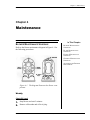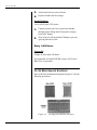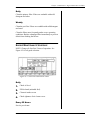
1
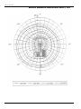
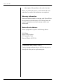
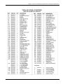
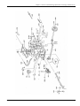
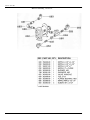
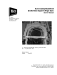
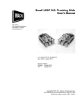
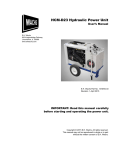
Trav-L-Vac 300
User’s Manual
E.H. Wachs
600 Knightsbridge Parkway
Lincolnshire, IL 60069
www.ehwachs.com
E.H. Wachs Part No. 59-MAN-01
Rev. A, October 2013
Revision History:
Original January 2003
Copyright © 2013 E.H. Wachs. All rights reserved.
This manual may not be reproduced in whole or in part
without the written consent of E.H. Wachs.
Trav-L-Vac 300
Part No. 59-MAN-01, Rev. A
E.H. Wachs
Table of Contents
Table of Contents
Chapter 1: About the Trav-L-Vac . . . . . . . . . . . . . . . . . . . . . . . . . . . . . . . . . . . . . . . . . . . . . . . 1
Purpose of This Manual . . . . . . . . . . . . . . . . . . . . . . . . . . . . . . . . . . . . . . . . . . . . . . . . . . . . . . . . . 1
How to Use The Manual . . . . . . . . . . . . . . . . . . . . . . . . . . . . . . . . . . . . . . . . . . . . . . . . . . . . . . . . 1
Symbols and Warnings . . . . . . . . . . . . . . . . . . . . . . . . . . . . . . . . . . . . . . . . . . . . . . . . . . . . . . . . . 2
Equipment Description . . . . . . . . . . . . . . . . . . . . . . . . . . . . . . . . . . . . . . . . . . . . . . . . . . . . . . . . . 3
Standard Features . . . . . . . . . . . . . . . . . . . . . . . . . . . . . . . . . . . . . . . . . . . . . . . . . . . . . . . . . . . 3
Optional Features . . . . . . . . . . . . . . . . . . . . . . . . . . . . . . . . . . . . . . . . . . . . . . . . . . . . . . . . . . . 4
Specifications . . . . . . . . . . . . . . . . . . . . . . . . . . . . . . . . . . . . . . . . . . . . . . . . . . . . . . . . . . . . . . 4
Power Source . . . . . . . . . . . . . . . . . . . . . . . . . . . . . . . . . . . . . . . . . . . . . . . . . . . . . . . . . . . 4
Blower . . . . . . . . . . . . . . . . . . . . . . . . . . . . . . . . . . . . . . . . . . . . . . . . . . . . . . . . . . . . . . . . 4
Filtration . . . . . . . . . . . . . . . . . . . . . . . . . . . . . . . . . . . . . . . . . . . . . . . . . . . . . . . . . . . . . . . 4
Holding Tank . . . . . . . . . . . . . . . . . . . . . . . . . . . . . . . . . . . . . . . . . . . . . . . . . . . . . . . . . . . 5
Finish . . . . . . . . . . . . . . . . . . . . . . . . . . . . . . . . . . . . . . . . . . . . . . . . . . . . . . . . . . . . . . . . . 5
Dimensions and Weight . . . . . . . . . . . . . . . . . . . . . . . . . . . . . . . . . . . . . . . . . . . . . . . . . . . 5
Battery . . . . . . . . . . . . . . . . . . . . . . . . . . . . . . . . . . . . . . . . . . . . . . . . . . . . . . . . . . . . . . . . 5
Gas Tank . . . . . . . . . . . . . . . . . . . . . . . . . . . . . . . . . . . . . . . . . . . . . . . . . . . . . . . . . . . . . . 5
Trailer Bolt-On Kit (Optional) . . . . . . . . . . . . . . . . . . . . . . . . . . . . . . . . . . . . . . . . . . . . . . 5
Acoustic Evaluation Sound Decibel Level @ 10 ft 6
Performance Charts 7
Chapter 2: Safety . . . . . . . . . . . . . . . . . . . . . . . . . . . . . . . . . . . . . . . . . . . . . . . . . . . . . . . . . . . . . 9
Operator Safety . . . . . . . . . . . . . . . . . . . . . . . . . . . . . . . . . . . . . . . . . . . . . . . . . . . . . . . . . . . . . . . 9
Safety Symbols . . . . . . . . . . . . . . . . . . . . . . . . . . . . . . . . . . . . . . . . . . . . . . . . . . . . . . . . . . . 10
Protective Equipment Requirements . . . . . . . . . . . . . . . . . . . . . . . . . . . . . . . . . . . . . . . . . . . 11
Chapter 3: Operating Instructions . . . . . . . . . . . . . . . . . . . . . . . . . . . . . . . . . . . . . . . . . . . . . . 13
Assembling the Trailer Package . . . . . . . . . . . . . . . . . . . . . . . . . . . . . . . . . . . . . . . . . . . . . . . . . 13
Operating Procedure . . . . . . . . . . . . . . . . . . . . . . . . . . . . . . . . . . . . . . . . . . . . . . . . . . . . . . . . . . 16
Pre-Operation Checklist . . . . . . . . . . . . . . . . . . . . . . . . . . . . . . . . . . . . . . . . . . . . . . . . . . . . . 16
Set-Up Procedure . . . . . . . . . . . . . . . . . . . . . . . . . . . . . . . . . . . . . . . . . . . . . . . . . . . . . . . . . . 17
Operation . . . . . . . . . . . . . . . . . . . . . . . . . . . . . . . . . . . . . . . . . . . . . . . . . . . . . . . . . . . . . . . . 17
Dumping Procedure . . . . . . . . . . . . . . . . . . . . . . . . . . . . . . . . . . . . . . . . . . . . . . . . . . . . . . . . 19
Operating Tips . . . . . . . . . . . . . . . . . . . . . . . . . . . . . . . . . . . . . . . . . . . . . . . . . . . . . . . . . . . . 20
Chapter 4: Maintenance . . . . . . . . . . . . . . . . . . . . . . . . . . . . . . . . . . . . . . . . . . . . . . . . . . . . . . 21
Blower Maintenance Schedule . . . . . . . . . . . . . . . . . . . . . . . . . . . . . . . . . . . . . . . . . . . . . . . . . . 21
Weekly . . . . . . . . . . . . . . . . . . . . . . . . . . . . . . . . . . . . . . . . . . . . . . . . . . . . . . . . . . . . . . . . . . 21
Check Oil Level . . . . . . . . . . . . . . . . . . . . . . . . . . . . . . . . . . . . . . . . . . . . . . . . . . . . . . . . 21
Grease Bearings . . . . . . . . . . . . . . . . . . . . . . . . . . . . . . . . . . . . . . . . . . . . . . . . . . . . . . . . 22
Every 1,000 Hours . . . . . . . . . . . . . . . . . . . . . . . . . . . . . . . . . . . . . . . . . . . . . . . . . . . . . . . . . 22
E.H. Wachs
Part No. 59-MAN-01, Rev. A
1
Trav-L-Vac 300
Change Oil . . . . . . . . . . . . . . . . . . . . . . . . . . . . . . . . . . . . . . . . . . . . . . . . . . . . . . . . . . . .
Filter Maintenance Schedule . . . . . . . . . . . . . . . . . . . . . . . . . . . . . . . . . . . . . . . . . . . . . . . . . . . .
Daily . . . . . . . . . . . . . . . . . . . . . . . . . . . . . . . . . . . . . . . . . . . . . . . . . . . . . . . . . . . . . . . . . . .
Weekly . . . . . . . . . . . . . . . . . . . . . . . . . . . . . . . . . . . . . . . . . . . . . . . . . . . . . . . . . . . . . . . . . .
Engine Maintenance Schedule . . . . . . . . . . . . . . . . . . . . . . . . . . . . . . . . . . . . . . . . . . . . . . . . . . .
Daily . . . . . . . . . . . . . . . . . . . . . . . . . . . . . . . . . . . . . . . . . . . . . . . . . . . . . . . . . . . . . . . . . . .
Every 25 Hours . . . . . . . . . . . . . . . . . . . . . . . . . . . . . . . . . . . . . . . . . . . . . . . . . . . . . . . . . . .
Every 100 Hours . . . . . . . . . . . . . . . . . . . . . . . . . . . . . . . . . . . . . . . . . . . . . . . . . . . . . . . . . .
Every 200 Hours . . . . . . . . . . . . . . . . . . . . . . . . . . . . . . . . . . . . . . . . . . . . . . . . . . . . . . . . . .
General Maintenance Schedule . . . . . . . . . . . . . . . . . . . . . . . . . . . . . . . . . . . . . . . . . . . . . . . . . .
Daily . . . . . . . . . . . . . . . . . . . . . . . . . . . . . . . . . . . . . . . . . . . . . . . . . . . . . . . . . . . . . . . . . . .
Weekly . . . . . . . . . . . . . . . . . . . . . . . . . . . . . . . . . . . . . . . . . . . . . . . . . . . . . . . . . . . . . . . . . .
Monthly . . . . . . . . . . . . . . . . . . . . . . . . . . . . . . . . . . . . . . . . . . . . . . . . . . . . . . . . . . . . . . . . .
Adjusting the Blower Drive Belts . . . . . . . . . . . . . . . . . . . . . . . . . . . . . . . . . . . . . . . . . . . . . . . .
22
22
23
23
23
23
23
24
24
24
24
24
24
25
Chapter 5: Parts List and Ordering Information . . . . . . . . . . . . . . . . . . . . . . . . . . . . . . . . . .
Ordering Information . . . . . . . . . . . . . . . . . . . . . . . . . . . . . . . . . . . . . . . . . . . . . . . . . . . . . . . . . .
Ordering Replacement Parts . . . . . . . . . . . . . . . . . . . . . . . . . . . . . . . . . . . . . . . . . . . . . . . . .
Repair Information . . . . . . . . . . . . . . . . . . . . . . . . . . . . . . . . . . . . . . . . . . . . . . . . . . . . . . . .
Warranty Information . . . . . . . . . . . . . . . . . . . . . . . . . . . . . . . . . . . . . . . . . . . . . . . . . . . . . .
Return Goods Address . . . . . . . . . . . . . . . . . . . . . . . . . . . . . . . . . . . . . . . . . . . . . . . . . . . . . .
Drawings and Parts Lists . . . . . . . . . . . . . . . . . . . . . . . . . . . . . . . . . . . . . . . . . . . . . . . . . . . . . .
27
27
27
27
28
28
28
2
Part No. 59-MAN-01, Rev. A
E.H. Wachs
Chapter 1, About the Trav-L-Vac
Chapter 1
About the Trav-L-Vac
PURPOSE OF THIS MANUAL
This manual explains how to operate and maintain the
Trav-L-Vac 300. It includes instructions for set-up, operation, and maintenance. It also contains parts lists, diagrams,
and service information to help you order replacement parts
and perform user-serviceable repairs.
In This Chapter
PURPOSE OF THIS MANUAL
HOW TO USE THE MANUAL
SYMBOLS AND WARNINGS
EQUIPMENT DESCRIPTION
Before operating the Trav-L-Vac (TLV), you should read
through this manual and become familiar with all instructions.
HOW TO USE THE MANUAL
This manual is organized to help you quickly find the information you need. Each chapter describes a specific topic on
using or maintaining your equipment.
Throughout this manual, refer
to this column for warnings,
cautions, and notices with
supplementary information.
Each page is designed with two columns. This large column
on the inside of the page contains instructions and illustrations. Use these instructions to operate and maintain the
equipment.
The narrower column on the outside contains additional
information such as warnings, special notes, and definitions. Refer to it for safety notes and other information.
E.H. Wachs
Part No. 59-MAN-01, Rev. A
1
Trav-L-Vac 300
SYMBOLS AND WARNINGS
The following symbols are used throughout this manual to
indicate special notes and warnings. They appear in the outside column of the page, next to the section they refer to.
Make sure you understand what each symbol means, and
follow all instructions for cautions and warnings.
WARNING
A WARNING alert with the
safety alert symbol indicates
a potentially hazardous situation that could result in serious injury or death.
This is the safety alert symbol. It is used
to alert you to potential personal injury
hazards. Obey all safety messages that
follow this symbol to avoid possible
injury or death.
CAUTION
A CAUTION alert with the
safety alert symbol indicates
a potentially hazardous situation that could result in
minor or moderate injury.
CAUTION
A CAUTION alert with the
damage alert symbol indicates a situation that will
result in damage to the
equipment.
This is the equipment damage alert
symbol. It is used to alert you to potential equipment damage situations.
Obey all messages that follow this symbol to avoid damaging the equipment or
workpiece on which it is operating.
IMPORTANT
An IMPORTANT alert with
the damage alert symbol indicates a situation that may
result in damage to the
equipment.
2
Part No. 59-MAN-01, Rev. A
E.H. Wachs
Chapter 1, About the Trav-L-Vac: Equipment Description
NOTE
NOTE
This symbol indicates a user note. Notes
provide additional information to supplement the instructions, or tips for easier
operation.
A NOTE provides supplementary information or operating tips.
EQUIPMENT DESCRIPTION
Wachs Trav-L-Vac (TLV) Transportable Vacuum Systems
are designed for a wide variety of field applications, including curb box, valve box, catch basin and vault clean out;
cleanup of sludge and industrial spills; and key hole excavation for curb box installation or replacement. Trav-L-Vac
systems are completely self contained, built on a structural
steel base with the following components:
•
•
•
•
•
engine
holding tank
blower
filtration system
suction tube.
The Trav-L-Vac 300, the smallest model of the Trav-L-Vac
line, features strong lifting capability and the largest capacity holding tank in its class. It handles solid and liquid
debris safely and quickly. The system is available in skid
mount configuration for operation from pickup truck beds,
or as a compact trailer system for towing to jobsites.
Standard Features
•
•
•
•
•
•
•
•
Fabricated base of channeled steel and steel plate with
fork lift slots.
Large capacity holding tank with manually activated
dump gate and 2" (51 mm) drain plug.
3-stage filtration system.
Heavy-duty positive displacement blower with silencer.
Vacuum relief valve.
Gasoline drive.
2-1/2" (64 mm) diameter x 10' (3.0 m) flexible wire
reinforced rubber suction hose.
2" (51 mm) diameter x 6-1/2' (2.0 m) steel suction tube
with handles.
E.H. Wachs
Part No. 59-MAN-01, Rev. A
3
Trav-L-Vac 300
•
•
•
Quick disconnect cam lock couplings.
High liquid level shut off switch.
Hour meter & tachometer.
Optional Features
•
•
•
•
Trailer package.
Light package.
Suction tubes.
Custom colors.
Specifications
Power Source
•
20 HP gasoline engine.
The Trav-L-Vav 300 uses a Kohler 20 HP twin cylinder, air
cooled gasoline engine. Controls include electric key start
and speed control. The engine has been factory pre-tested.
Blower
•
•
•
Belt drive positive displacement rotary lobe impeller
type with 14"(356 mm) Hg maximum capacity.
345 CFM (9.77 cmm) @ 3600 RPM with 14" (356 mm)
Hg.
15,813 FPM (4,819.8 cmm) air velocity through 2" (51
mm) diameter inlet
The Roots Universal 45 RAI series blower has been properly lubricated at the factory. Enclosed with the Trav-L-Vac
manual is the Roots Blower manual; refer to it for specifications, maintenance, and repair information.
Filtration
•
•
•
•
4
Primary drum filter with 2" (51 mm) of polyethylene
foam.
Secondary filter of fine polyethylene foam.
Final filter, 10 micron polyester cartridge.
All filters are washable with water.
Part No. 59-MAN-01, Rev. A
E.H. Wachs
Chapter 1, About the Trav-L-Vac: Equipment Description
A three-stage system, accessed from top of holding tank,
using toggle clamp to lock filters in place. Easy clean with
mild soap and water.
Holding Tank
•
•
•
•
12 ft3 (0.34 m3)/90 liquid gal. (33.7 l) actual holding
capacity.
32" (813 mm) diameter.
Equipped with vacuum relief valve, high level liquid
shut off switch, and hinged dump gate.
2" (51 mm) drain plug.
Finish
Durable painted finish w/plated fasteners throughout.
Dimensions and Weight
(LxWxH): 40"x 60"x 55"(1,016 x 1,524 x 1,397 mm)
950 lb (430.9 kg)
Battery
For shipping purposes, the battery is left empty. Battery acid
is shipped separately, allowing for the customer to fill the
battery upon delivery.
Gas Tank
Use only regular grade unleaded gasoline with an octane
rating of 87 or higher.
•
•
6 gallon capacity
Always keep gas cap vent in the full open position.
Trailer Bolt-On Kit (Optional)
•
•
•
•
•
2,300 lb trailer capacity.
Torsion axle.
2" ball coupler or pintle.
105" overall length.
63" overall width.
E.H. Wachs
Part No. 59-MAN-01, Rev. A
5
Trav-L-Vac 300
Acoustic Evaluation Sound Decibel Level @ 10 ft
6
Part No. 59-MAN-01, Rev. A
E.H. Wachs
Chapter 1, About the Trav-L-Vac: Equipment Description
Performance Charts
E.H. Wachs
Part No. 59-MAN-01, Rev. A
7
Trav-L-Vac 300
8
Part No. 59-MAN-01, Rev. A
E.H. Wachs
Chapter 2, Safety
Chapter 2
Safety
E.H. Wachs takes great pride in designing and manufacturing safe, high-quality products. We make user safety a top
priority in the design of all our products.
Read this chapter carefully before operating the equipment.
It contains important safety instructions and recommendations.
OPERATOR SAFETY
Follow these guidelines for safe operation of the equipment.
•
•
•
•
READ THE OPERATING MANUAL. Make sure
you understand all setup and operating instructions
before you begin.
INSPECT MACHINE AND ACCESSORIES.
Before starting the machine, look for loose bolts or
nuts, leaking lubricant, rusted components, and any
other physical conditions that may affect operation.
Properly maintaining the machine can greatly decrease
the chances for injury.
ALWAYS READ PLACARDS AND LABELS. Make
sure all placards, labels, and stickers are clearly legible
and in good condition. You can purchase replacement
labels from E.H. Wachs Company.
KEEP CLEAR OF MOVING PARTS. Keep hands,
arms, and fingers clear of all rotating or moving parts.
E.H. Wachs
Part No. 59-MAN-01, Rev. A
Look for this symbol throughout the
manual. It indicates
a personal injury
hazard.
9
Trav-L-Vac 300
•
•
•
•
•
•
•
•
•
•
•
Always turn machine off before doing any adjustments
or service.
SECURE LOOSE CLOTHING AND JEWELRY.
Secure or remove loose-fitting clothing and jewelry, and
securely bind long hair, to prevent them from getting
caught in moving parts of the machine.
KEEP WORK AREA CLEAR. Keep all clutter and
nonessential materials out of the work area. Only people
directly involved with the work being performed should
have access to the area.
KEEP CLEAR OF VACUUM HOSE WHEN OPERATING VACUUM. Keep hands, arms and fingers clear
of vacuum inlet. Always turn machine off before making any adjustments or changing wands.
Take care in transporting vacuum system. Always check
trailer hitch, install safety chains, and check brake lights
and turn signals.
Do not run engine in enclose area. Exhaust fumes are
deadly.
Do not smoke when filling fuel tank or operating vacuum system.
Do not allow grass, leaves, dirt, rags, or combustible
materials to accumulate around engine and muffler.
Use this tool for the intended purpose only.
Do not fill or empty vacuum tank without trailer connected to towing vehicle (trailer configuration), or frame
bolted to trailer bed (skid mount configuration).
Shut system down before performing any service to the
equipment.
Use all appropriate and required personal protective
equipment, such as safety shoes, hard hat, safety
glasses, hearing protection, etc.
Safety Symbols
This icon is displayed with any safety alert that indicates a
personal injury hazard.
WARNING
This safety alert indicates a potentially hazardous situation
that, if not avoided, could result in death or serious injury.
10
Part No. 59-MAN-01, Rev. A
E.H. Wachs
Chapter 2, Safety: Operator Safety
CAUTION
This safety alert, with the personal injury hazard symbol,
indicates a potentially hazardous situation that, if not
avoided, could result in minor or moderate injury.
Protective Equipment Requirements
WARNING
Always wear impact resistant eye protection while operating or working near
this equipment.
For additional information on eye and face protection, refer
to Federal OSHA regulations, 29 Code of Federal Regulations, Section 1910.133., Eye and Face Protection and
American National Standards Institute, ANSI Z87.1, Occupational and Educational Eye and Face Protection. Z87.1 is
available from the American National Standards Institute,
Inc., 1430 Broadway, New York, NY 10018.
CAUTION
Personal hearing protection is recommended when operating or working near
this tool.
Hearing protectors are required in high noise areas, 85 dBA
or greater. The operation of other tools and equipment in the
area, reflective surfaces, process noises, and resonant structures can increase the noise level in the area. For additional
information on hearing protection, refer to Federal OSHA
regulations, 29 Code of Federal Regulations, Section
1910.95, Occupational Noise Exposure and ANSI S12.6
Hearing Protectors.
E.H. Wachs
Part No. 59-MAN-01, Rev. A
11
Trav-L-Vac 300
12
Part No. 59-MAN-01, Rev. A
E.H. Wachs
Chapter 3, Operating Instructions
Chapter 3
Operating
Instructions
In This Chapter
ASSEMBLING THE TRAILER PACKAGE
The reference numbers (“ref”) in the following procedure
refer to the callouts in the installation diagram in Figure 31.
ASSEMBLING THE TRAILER
PACKAGE
OPERATING PROCEDURE
Figure 3-1. Refer to the reference numbers in the
installation diagram for the following steps.
1. Bolt the fender braces (ref. 076) to the dump gate
sides, using the following hardware:
E.H. Wachs
Part No. 59-MAN-01, Rev. A
13
Trav-L-Vac 300
• 3/8-16 x 3/4 HHCS
• 3/8 lock washers
• 3/8-16 hex nuts.
2. Align the holes in the fender with the holes in the TLV
frame (ref. 01). Secure the fenders (ref. 075) to the
fender braces, using the following hardware:
• 3/8-16 x 3/4 HHCS
• 3/8 lock washers
• 3/8-16 hex nuts.
3. Position the axle (ref. 078) under the frame with the
torsion arms trailing toward the dump gate. The axle is
bolted to the frame through the holes closest to the
tongue side of the frame.
4. Join the fenders to the axle, through the frame, using
the following hardware:
•
•
•
•
1/2-13 x 4-1/2 HHCS (ref. 6)
1/2 flat washers (ref. 3)
1/2 lock washers (ref. 4)
1/2-13 hex nuts (ref. 5).
NOTE: Make sure the axle is
mounted perpendicular to the
direction of travel. A misaligned axle will cause the
trailer to tow badly and will
decrease tire life.
Figure 3-2. Assemble the fenders, frame, and axle as
shown.
5. Place the center caps (ref. 081) in the rim and mount
the wheels (ref. 079) on the axle, using the lug nuts
(ref. 080).
6. Pull the wire harness (ref. 084) wires through the hole
at the back of the tongue receiver. Do not remove the
protective loom from the wires.
14
Part No. 59-MAN-01, Rev. A
E.H. Wachs
Chapter 3, Operating Instructions: Assembling the Trailer Package
7. Insert the tongue (ref. 077) into the receivers. Be sure
to pull the excess wire with the tongue to avoid damage.
8. Line up the holes in the tongue with the holes in the
receiver. Secure the tongue in place, using the supplied pull pins (ref. 090) and keeper pins.
9. Attach the jack (ref. 103) to the tongue, using the supplied snap ring (ref. 104).
10. Pull the trailer wires through the holes under the TLV
frame until they come out the back corner, beneath the
drain plug.
11. Secure the wiring to the frame, using the supplied
adhesive wire clips (ref. 106).
12. Pull the green and brown wires (for the RIGHT tail
light) up through the conduit directly above the exit
hole.
13. The yellow and brown wires (for the LEFT tail light)
are strung along the TLV frame below the dump gate.
Figure 3-3. Wire the tail lights as illustrated.
14. Secure the wires to the pre-drilled holes in the frame,
using wire clamps and #10 self drilling hex head
screws.
15. Pull the yellow and brown wires up through the conduit and out through the hole near the fender brace.
16. Remove the slack from the trailer wires and secure
them to the fender braces, using the supplied adhesive
wire clips.
E.H. Wachs
Part No. 59-MAN-01, Rev. A
15
Trav-L-Vac 300
17. Cut the trailer wires, allowing sufficient length to connect the tail lights (ref. 082 & 083).
18. Strip the ends of the trailer wires 1/2".
19. Feed the trailer wires through the upper slots on the
fender braces.
20. Push the stripped brown ends into the hole on the
trailer lights marked TAIL.
21. Push the stripped green and yellow ends into the hole
on the trailer lights marked STOP.
22. Bolt the trailer lights to the fender braces, using 1/4-20
hex nuts and 1/4 lock washers.
23. Check that the lights are working properly.
24. Attach your license plate through the holes on the
LEFT fender brace. Apply the amber side markers on
each side of the TLV 300 frame.
OPERATING PROCEDURE
Pre-Operation Checklist
1. Make sure all scheduled maintenance has been prop-
erly performed. See the maintenance in Chapter 4, or
refer to the maintenance decal on the TLV-300.
2. Make sure that the hitch assembly is properly attached
to the towing vehicle.
3. Check trailer brake lights and turn signals.
4. Check the TLV-300 engine fuel level.
5. Make sure the battery is charged.
6. Make sure the suction hose and suction tubes are
stored on board the TLV-300.
7. Check the drive belt tension. Adjust as necessary.
(Refer to the drive belt tensioning diagram in Chapter
4.)
16
Part No. 59-MAN-01, Rev. A
E.H. Wachs
Chapter 3, Operating Instructions: Operating Procedure
Set-Up Procedure
1. Position the TLV system near the work area.
2. Connect the suction hose to the coupling on the vacuum inlet port.
Figure 3-4. Connect the suction hose to the vacuum
inlet port.
3. Connect the other end of the suction hose to the coupling on the suction tube.
Operation
1. Start the engine and allow it to idle several minutes to
properly warm up.
E.H. Wachs
Part No. 59-MAN-01, Rev. A
17
Trav-L-Vac 300
Figure 3-5. Use the key starter to start the engine.
2. Make sure the vacuum diverter valve is closed. If the
diverter valve is open, there will be no suction at the
wand opening.
3. Bring engine RPM up to full running speed.
NOTE: If a clog occurs,
shake suction hose. If clog
remains, open the vacuum
diverter valve to remove vacuum from suction hose. Disconnect the hose from the
TLV. Either use a ram to dislodge clogged debris or
reverse suction hose ends.
4. Lower the suction tube into valve box until it contacts
either water or debris. Extract debris until the valve
box is empty, or until the TLV-300 holding tank is full.
Figure 3-6. Use the suction tube to extract water and
debris from the valve box.
18
Part No. 59-MAN-01, Rev. A
E.H. Wachs
Chapter 3, Operating Instructions: Operating Procedure
5. If the tank fills with liquid to its limit, the high liquid
level switch will automatically shut off the engine.
You must drain the holding tank before the engine can
be restarted.
6. After the vacuum operation is over, run the engine for
NOTE: If removing heavier or
solid debris, the high liquid
level switch may not shut off
the unit. Periodically check
the holding tank to avoid over
filling.
several minutes to clear out any water that may have
reached the blower.
7. Consult the manufacturer for special operating suggestions concerning use in freezing weather.
Dumping Procedure
1. Shut off the engine.
2. Position the TLV-300 over the dumping area.
3. Remove the tank drain plug to allow any liquids in the
tank to drain.
4. Once liquid has drained, open the dump gate and
remove any solid debris.
Figure 3-7. Open the dump gate to remove solid
debris from the tank.
5. Clean the primary filter. You can use plain water,
though mild soap mixed with water is recommended if
available.
E.H. Wachs
Part No. 59-MAN-01, Rev. A
19
Trav-L-Vac 300
Figure 3-8. Open the tank lid and clean the filter after
each use.
6. Flush out the suction tubes and suction hose.
Operating Tips
1. While excavating water, make sure to submerge the
suction tube completely.
2. If debris is packed in the bottom of the valve box,
rotate the suction tube assembly back and forth to
break up debris.
3. For solid debris, pour water into the valve box to
speed up debris removal.
4. If the suction tube becomes clogged, use a rod that fits
inside the tube to remove the blockage.
5. Flush out suction tubes and suction hoses prior to storage.
6. Perform all scheduled maintenance at the designated
times to ensure peak performance and increase the
operating life of the TLV-300.
20
Part No. 59-MAN-01, Rev. A
E.H. Wachs
Chapter 4, Maintenance
Chapter 4
Maintenance
BLOWER MAINTENANCE SCHEDULE
Refer to the blower maintenance diagram in Figure 4-1 for
the following procedures.
In This Chapter
BLOWER MAINTENANCE
SCHEDULE
FILTER MAINTENANCE
SCHEDULE
ENGINE MAINTENANCE
SCHEDULE
GENERAL MAINTENANCE
SCHEDULE
ADJUSTING THE BLOWER
DRIVE BELTS
Figure 4-1. The diagram illustrates the blower components.
Weekly
Check Oil Level
1. Stop blower and wait 5 minutes.
2. Remove oil breather and oil level plug.
E.H. Wachs
Part No. 59-MAN-01, Rev. A
21
Trav-L-Vac 300
3. Add oil until oil runs out level holes.
4. Replace breather and level plugs.
Grease Bearings
Use an NLGI grade 2 EP grease.
1. Using a pressure gun, force grease into housing
through grease fittings until clean grease emerges
from relief fittings.
2. Wipe all grease off around relief fittings to prevent
spraying onto drive belts.
Every 1,000 Hours
Change Oil
Change oil after initial 100 hours.
Recommended oil: Mobil DTE BB, Amoco 220, Texaco
R&O 220, or equivalent.
FILTER MAINTENANCE SCHEDULE
Refer to the filter maintenance diagram in Figure 4-2 for the
following procedures.
Figure 4-2. The diagram illustrates the filters.
22
Part No. 59-MAN-01, Rev. A
E.H. Wachs
Chapter 4, Maintenance: Engine Maintenance Schedule
Daily
Clean the primary filter. Filters are washable with mild
detergent and water.
Weekly
Clean the pre-filter. Filters are washable with mild detergent
and water.
Clean the filters more frequently under severe operating
conditions. Replace a damaged filter immediately to prevent
debris from reaching the blower.
ENGINE MAINTENANCE SCHEDULE
NOTE: Change oil after first 5 hours of operation. See
Figure 4-3 for oil grade selection.
Figure 4-3. Select oil based on the chart.
Daily
1. Check oil level.
2. Fill fuel tank (unleaded fuel).
3. Clean air intake screen.
4. Check tightness of air cleaner cover.
Every 25 Hours
Service pre-cleaner.
E.H. Wachs
Part No. 59-MAN-01, Rev. A
23
Trav-L-Vac 300
Every 100 Hours
1. Service paper element.
2. Remove shrouds to clean cooling fins and external
surfaces.
3. Check battery electrolyte level.
4. Change oil.
Every 200 Hours
1. Check spark plug condition and gap.
2. Change oil filter.
GENERAL MAINTENANCE SCHEDULE
Daily
1. Check suction hoses for any abrasions, holes, kinks or
damaged connectors. Replace as needed.
2. Verify that all dump gate and filter lid clamps are
secured tightly. Adjust if necessary.
3. Clean any debris from dump door seal.
4. Verify that all trailer and/or accessory lights are functioning properly. Repair or replace as needed.
Weekly
1. Clean debris build-up from holding tank.
2. Check lug nuts and fasteners for tightness. Tighten as
necessary.
Monthly
1. Check blower drive belts for proper tension, and for
frayed or cracked condition. Adjust or replace as
needed.
24
Part No. 59-MAN-01, Rev. A
E.H. Wachs
Chapter 4, Maintenance: Adjusting the Blower Drive Belts
2. Check for loose piping, fittings, and connectors.
Tighten as needed.
3. Check tire pressure. Fill as necessary.
ADJUSTING THE BLOWER DRIVE BELTS
1. Loosen the 3/4” hex nut on the tensioning shaft (ref.
012).
2. Rotate the tensioning shaft to the right to tighten the
belts, or to the left to loosen the belts.
3. Lock the shaft in place by re-tightening the 3/4” hex
nut.
Figure 4-4. Adjust the belt tension by rotating the tensioning shaft (ref. 012).
E.H. Wachs
Part No. 59-MAN-01, Rev. A
25
Trav-L-Vac 300
26
Part No. 59-MAN-01, Rev. A
E.H. Wachs
Chapter 5, Parts List and Ordering Information
Chapter 5
Parts List and
Ordering Information
In This Chapter
ORDERING INFORMATION
ORDERING INFORMATION
DRAWINGS AND PARTS LISTS
To place an order, request service, or get more detailed
information on any E.H. Wachs Water Utility products, call
us at one of the following numbers:
U.S.
866-392-1060
International: 815-943-4785
You can also visit our Web site at:
www.ehwachs.com
Ordering Replacement Parts
When ordering parts, refer to the parts lists in this chapter.
Please provide the part description and part number for all
parts you are ordering.
Repair Information
Please call us for an authorization number before returning
any equipment for repair or factory service. We will advise
you of shipping and handling. When you send the equipment, please include the following information:
• Your name/company name
• Your address
• Your phone number
E.H. Wachs
Part No. 59-MAN-01, Rev. A
27
Trav-L-Vac 300
•
A description of the problem or the work to be done.
Before we perform any repair, we will estimate the work
and inform you of the cost and the time to complete it.
Warranty Information
Enclosed with the manual is a warranty card. Please fill out
the registration card and return to E.H. Wachs. Retain the
owner’s registration record and warranty card for your
information.
Return Goods Address
Return equipment for repair to the following address.
E.H. Wachs
Water Utility Products
455 Comanche Circle
Harvard, Illinois 60033 USA
DRAWINGS AND PARTS LISTS
Use the drawings and parts lists on the following pages to
identify and order spare or replacement parts.
28
Part No. 59-MAN-01, Rev. A
E.H. Wachs
Chapter 5, Parts List and Ordering Information: Drawings and Parts Lists
E.H. Wachs
Part No. 59-MAN-01, Rev. A
29
Trav-L-Vac 300
30
Part No. 59-MAN-01, Rev. A
E.H. Wachs
Chapter 5, Parts List and Ordering Information: Drawings and Parts Lists
E.H. Wachs
Part No. 59-MAN-01, Rev. A
31
Trav-L-Vac 300
Blower Assembly, 59-302-01
32
Part No. 59-MAN-01, Rev. A
E.H. Wachs