1
UM0097
User manual
STR71x firmware library
Introduction
About this manual
This document is the STR71x firmware library user manual. It describes the STR71x
peripheral firmware library: a collection of routines, data structures and macros that cover
the features of each peripheral.
The firmware library user manual is structured as follows:
●
Definitions, document conventions and firmware library rules
●
Overview of the firmware library (package content, library structure), installation
guidelines, and examples of how to use the library.
●
Detailed description the firmware library: configuration structure and function
descriptions for each peripheral in detail.
About STR71x firmware library
The STR71x firmware library is a firmware package consisting of device drivers for all
standard STR71x peripherals. You can use any STR71x device in applications without indepth study of each peripheral specification. As a result, using this library can save you a lot
of the time that you would otherwise spend in coding and also the cost of developing and
integrating your application.
Each device driver consists of a set of functions covering the functionality of the peripheral.
Since all the STR71x peripherals and their corresponding registers are memory-mapped, a
peripheral can be easily controlled using ‘C’ code. The source code, developed in ‘C’, is fully
documented. A basic knowledge of ‘C’ programming is required.
The library contains a complete firmware in ‘C’ and it is independent from any software toolchains. Only the start-up files are tool-chain dependent.
Since the library is generic and covers all of the capabilities of each peripheral, it may not be
as efficient as it could be from a code size and/or execution speed point of view. For many
applications the library may be used as is. However, for applications with strong constraints
in terms of code size and/or execution speed, the library drivers should be used as a
reference, to show you how to configure the peripheral and which you can then tailor to your
specific application requirements.
September 2007
Rev 3
1/229
www.st.com
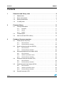
Contents
UM0097
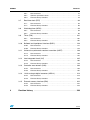
Contents
1
2
Document and library rules . . . . . . . . . . . . . . . . . . . . . . . . . . . . . . . . . . . 6
1.1
Abbreviations . . . . . . . . . . . . . . . . . . . . . . . . . . . . . . . . . . . . . . . . . . . . . . . 6
1.2
Styles and symbols . . . . . . . . . . . . . . . . . . . . . . . . . . . . . . . . . . . . . . . . . . 6
1.3
Naming conventions . . . . . . . . . . . . . . . . . . . . . . . . . . . . . . . . . . . . . . . . . . 7
1.4
C coding rules . . . . . . . . . . . . . . . . . . . . . . . . . . . . . . . . . . . . . . . . . . . . . . 7
Firmware library . . . . . . . . . . . . . . . . . . . . . . . . . . . . . . . . . . . . . . . . . . . 11
2.1
3
2.1.1
Examples . . . . . . . . . . . . . . . . . . . . . . . . . . . . . . . . . . . . . . . . . . . . . . . . 11
2.1.2
Library . . . . . . . . . . . . . . . . . . . . . . . . . . . . . . . . . . . . . . . . . . . . . . . . . . 12
2.1.3
Project . . . . . . . . . . . . . . . . . . . . . . . . . . . . . . . . . . . . . . . . . . . . . . . . . . 12
2.2
File description . . . . . . . . . . . . . . . . . . . . . . . . . . . . . . . . . . . . . . . . . . . . . 12
2.3
How to use the STR71x library . . . . . . . . . . . . . . . . . . . . . . . . . . . . . . . . 14
Peripheral firmware overview . . . . . . . . . . . . . . . . . . . . . . . . . . . . . . . . . 17
3.1
3.2
3.3
3.4
3.5
3.6
2/229
Package description . . . . . . . . . . . . . . . . . . . . . . . . . . . . . . . . . . . . . . . . . 11
Power control unit (PCU) . . . . . . . . . . . . . . . . . . . . . . . . . . . . . . . . . . . . . 17
3.1.1
Data structures . . . . . . . . . . . . . . . . . . . . . . . . . . . . . . . . . . . . . . . . . . . 17
3.1.2
Firmware library functions . . . . . . . . . . . . . . . . . . . . . . . . . . . . . . . . . . . 20
Reset and clock control unit (RCCU) . . . . . . . . . . . . . . . . . . . . . . . . . . . . 29
3.2.1
Data structures . . . . . . . . . . . . . . . . . . . . . . . . . . . . . . . . . . . . . . . . . . . 29
3.2.2
Firmware library functions . . . . . . . . . . . . . . . . . . . . . . . . . . . . . . . . . . . 36
Advanced peripheral bus bridges (APB) . . . . . . . . . . . . . . . . . . . . . . . . . 47
3.3.1
Data structures . . . . . . . . . . . . . . . . . . . . . . . . . . . . . . . . . . . . . . . . . . . 47
3.3.2
Common parameter values . . . . . . . . . . . . . . . . . . . . . . . . . . . . . . . . . . 50
3.3.3
Firmware library functions . . . . . . . . . . . . . . . . . . . . . . . . . . . . . . . . . . . 50
Enhanced interrupt controller (EIC) . . . . . . . . . . . . . . . . . . . . . . . . . . . . . 52
3.4.1
Data structures . . . . . . . . . . . . . . . . . . . . . . . . . . . . . . . . . . . . . . . . . . . 53
3.4.2
Firmware library functions . . . . . . . . . . . . . . . . . . . . . . . . . . . . . . . . . . . 56
General purpose input output (GPIO) . . . . . . . . . . . . . . . . . . . . . . . . . . . 65
3.5.1
Data structures . . . . . . . . . . . . . . . . . . . . . . . . . . . . . . . . . . . . . . . . . . . 65
3.5.2
Common parameter values . . . . . . . . . . . . . . . . . . . . . . . . . . . . . . . . . . 68
3.5.3
Firmware library functions . . . . . . . . . . . . . . . . . . . . . . . . . . . . . . . . . . . 69
External Interrupts (XTI) . . . . . . . . . . . . . . . . . . . . . . . . . . . . . . . . . . . . . . 75
UM0097
Contents
3.7
3.8
3.9
3.10
3.11
3.12
3.13
3.14
3.15
4
3.6.1
Data structures . . . . . . . . . . . . . . . . . . . . . . . . . . . . . . . . . . . . . . . . . . . 75
3.6.2
Common parameter values . . . . . . . . . . . . . . . . . . . . . . . . . . . . . . . . . . 77
3.6.3
Firmware library functions . . . . . . . . . . . . . . . . . . . . . . . . . . . . . . . . . . . 78
Real time clock (RTC) . . . . . . . . . . . . . . . . . . . . . . . . . . . . . . . . . . . . . . . 84
3.7.1
Data structures . . . . . . . . . . . . . . . . . . . . . . . . . . . . . . . . . . . . . . . . . . . 84
3.7.2
Firmware library functions . . . . . . . . . . . . . . . . . . . . . . . . . . . . . . . . . . . 86
Watchdog timer (WDG) . . . . . . . . . . . . . . . . . . . . . . . . . . . . . . . . . . . . . . 94
3.8.1
Data structures . . . . . . . . . . . . . . . . . . . . . . . . . . . . . . . . . . . . . . . . . . . 94
3.8.2
Firmware library functions . . . . . . . . . . . . . . . . . . . . . . . . . . . . . . . . . . . 96
Timer (TIM) . . . . . . . . . . . . . . . . . . . . . . . . . . . . . . . . . . . . . . . . . . . . . . . 101
3.9.1
Data structures . . . . . . . . . . . . . . . . . . . . . . . . . . . . . . . . . . . . . . . . . . 101
3.9.2
Firmware library functions . . . . . . . . . . . . . . . . . . . . . . . . . . . . . . . . . . 107
Buffered serial peripheral interface (BSPI) . . . . . . . . . . . . . . . . . . . . . . . 120
3.10.1
Data structures . . . . . . . . . . . . . . . . . . . . . . . . . . . . . . . . . . . . . . . . . . 121
3.10.2
Firmware library functions . . . . . . . . . . . . . . . . . . . . . . . . . . . . . . . . . . 124
Universal asynchronous receiver transmitter (UART) . . . . . . . . . . . . . . 140
3.11.1
Data structures . . . . . . . . . . . . . . . . . . . . . . . . . . . . . . . . . . . . . . . . . . 140
3.11.2
Firmware library functions . . . . . . . . . . . . . . . . . . . . . . . . . . . . . . . . . . 145
Inter-integrated circuit (I2C) . . . . . . . . . . . . . . . . . . . . . . . . . . . . . . . . . . 165
3.12.1
Data structures . . . . . . . . . . . . . . . . . . . . . . . . . . . . . . . . . . . . . . . . . . 165
3.12.2
Firmware library functions . . . . . . . . . . . . . . . . . . . . . . . . . . . . . . . . . . 170
Controller area network (CAN) . . . . . . . . . . . . . . . . . . . . . . . . . . . . . . . . 184
3.13.1
Data structures . . . . . . . . . . . . . . . . . . . . . . . . . . . . . . . . . . . . . . . . . . 184
3.13.2
Firmware library functions . . . . . . . . . . . . . . . . . . . . . . . . . . . . . . . . . . 192
12-bit analog-to-digital converter (ADC12) . . . . . . . . . . . . . . . . . . . . . . . 213
3.14.1
Data structures . . . . . . . . . . . . . . . . . . . . . . . . . . . . . . . . . . . . . . . . . . 213
3.14.2
Firmware library functions . . . . . . . . . . . . . . . . . . . . . . . . . . . . . . . . . . 216
External memory interface (EMI) . . . . . . . . . . . . . . . . . . . . . . . . . . . . . . 222
3.15.1
Data structures . . . . . . . . . . . . . . . . . . . . . . . . . . . . . . . . . . . . . . . . . . 222
3.15.2
Firmware library functions . . . . . . . . . . . . . . . . . . . . . . . . . . . . . . . . . . 224
Revision history . . . . . . . . . . . . . . . . . . . . . . . . . . . . . . . . . . . . . . . . . . 226
3/229
List of tables
UM0097
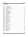
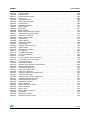
List of tables
Table 1.
Table 2.
Table 3.
Table 4.
Table 5.
Table 6.
Table 7.
Table 8.
Table 9.
Table 10.
Table 11.
Table 12.
Table 13.
Table 14.
Table 15.
Table 16.
Table 17.
Table 18.
Table 19.
Table 20.
Table 21.
Table 22.
Table 23.
Table 24.
Table 25.
Table 26.
Table 27.
Table 28.
Table 29.
Table 30.
Table 31.
Table 32.
Table 33.
Table 34.
Table 35.
Table 36.
Table 37.
Table 38.
Table 39.
Table 40.
Table 41.
Table 42.
Table 43.
Table 44.
Table 45.
Table 46.
Table 47.
Table 48.
4/229
List of acronyms . . . . . . . . . . . . . . . . . . . . . . . . . . . . . . . . . . . . . . . . . . . . . . . . . . . . . . . . . . 6
Source/header file list . . . . . . . . . . . . . . . . . . . . . . . . . . . . . . . . . . . . . . . . . . . . . . . . . . . . . 12
Peripheral firmware functions . . . . . . . . . . . . . . . . . . . . . . . . . . . . . . . . . . . . . . . . . . . . . . . 17
PCU structure fields . . . . . . . . . . . . . . . . . . . . . . . . . . . . . . . . . . . . . . . . . . . . . . . . . . . . . . 18
PCU voltage regulator status . . . . . . . . . . . . . . . . . . . . . . . . . . . . . . . . . . . . . . . . . . . . . . . 19
PCU voltage regulator descriptions . . . . . . . . . . . . . . . . . . . . . . . . . . . . . . . . . . . . . . . . . . 19
WFI clocks . . . . . . . . . . . . . . . . . . . . . . . . . . . . . . . . . . . . . . . . . . . . . . . . . . . . . . . . . . . . . 19
PCU flags . . . . . . . . . . . . . . . . . . . . . . . . . . . . . . . . . . . . . . . . . . . . . . . . . . . . . . . . . . . . . . 20
PCU library functions . . . . . . . . . . . . . . . . . . . . . . . . . . . . . . . . . . . . . . . . . . . . . . . . . . . . . 20
RCCU registers. . . . . . . . . . . . . . . . . . . . . . . . . . . . . . . . . . . . . . . . . . . . . . . . . . . . . . . . . . 30
Clock divider parameters . . . . . . . . . . . . . . . . . . . . . . . . . . . . . . . . . . . . . . . . . . . . . . . . . . 31
RCLK clock sources . . . . . . . . . . . . . . . . . . . . . . . . . . . . . . . . . . . . . . . . . . . . . . . . . . . . . . 31
PLL1 multiplication factors . . . . . . . . . . . . . . . . . . . . . . . . . . . . . . . . . . . . . . . . . . . . . . . . . 32
PLL2 multiplication factors . . . . . . . . . . . . . . . . . . . . . . . . . . . . . . . . . . . . . . . . . . . . . . . . . 32
PLL division factors. . . . . . . . . . . . . . . . . . . . . . . . . . . . . . . . . . . . . . . . . . . . . . . . . . . . . . . 33
USB clock sources . . . . . . . . . . . . . . . . . . . . . . . . . . . . . . . . . . . . . . . . . . . . . . . . . . . . . . . 33
RCCU internal clocks . . . . . . . . . . . . . . . . . . . . . . . . . . . . . . . . . . . . . . . . . . . . . . . . . . . . . 34
RCCU interrupts . . . . . . . . . . . . . . . . . . . . . . . . . . . . . . . . . . . . . . . . . . . . . . . . . . . . . . . . . 34
RCCU flags . . . . . . . . . . . . . . . . . . . . . . . . . . . . . . . . . . . . . . . . . . . . . . . . . . . . . . . . . . . . . 35
RCCU reset sources . . . . . . . . . . . . . . . . . . . . . . . . . . . . . . . . . . . . . . . . . . . . . . . . . . . . . . 35
PLL1 free running modes . . . . . . . . . . . . . . . . . . . . . . . . . . . . . . . . . . . . . . . . . . . . . . . . . . 36
APB registers . . . . . . . . . . . . . . . . . . . . . . . . . . . . . . . . . . . . . . . . . . . . . . . . . . . . . . . . . . . 47
Bridge peripheral codes . . . . . . . . . . . . . . . . . . . . . . . . . . . . . . . . . . . . . . . . . . . . . . . . . . . 49
APBx values . . . . . . . . . . . . . . . . . . . . . . . . . . . . . . . . . . . . . . . . . . . . . . . . . . . . . . . . . . . . 50
APB library functions . . . . . . . . . . . . . . . . . . . . . . . . . . . . . . . . . . . . . . . . . . . . . . . . . . . . . 50
EIC peripheral registers . . . . . . . . . . . . . . . . . . . . . . . . . . . . . . . . . . . . . . . . . . . . . . . . . . . 53
IRQChannel values. . . . . . . . . . . . . . . . . . . . . . . . . . . . . . . . . . . . . . . . . . . . . . . . . . . . . . . 55
FIQChannel values . . . . . . . . . . . . . . . . . . . . . . . . . . . . . . . . . . . . . . . . . . . . . . . . . . . . . . . 56
GPIO registers . . . . . . . . . . . . . . . . . . . . . . . . . . . . . . . . . . . . . . . . . . . . . . . . . . . . . . . . . . 66
GPIO pin modes . . . . . . . . . . . . . . . . . . . . . . . . . . . . . . . . . . . . . . . . . . . . . . . . . . . . . . . . . 67
Port_Pins parameter value . . . . . . . . . . . . . . . . . . . . . . . . . . . . . . . . . . . . . . . . . . . . . . . . . 68
GPIOx values . . . . . . . . . . . . . . . . . . . . . . . . . . . . . . . . . . . . . . . . . . . . . . . . . . . . . . . . . . . 68
GPIO library functions. . . . . . . . . . . . . . . . . . . . . . . . . . . . . . . . . . . . . . . . . . . . . . . . . . . . . 69
XTI registers . . . . . . . . . . . . . . . . . . . . . . . . . . . . . . . . . . . . . . . . . . . . . . . . . . . . . . . . . . . . 76
XTI modes . . . . . . . . . . . . . . . . . . . . . . . . . . . . . . . . . . . . . . . . . . . . . . . . . . . . . . . . . . . . . 77
Trigger edge polarity values . . . . . . . . . . . . . . . . . . . . . . . . . . . . . . . . . . . . . . . . . . . . . . . . 77
Lines values . . . . . . . . . . . . . . . . . . . . . . . . . . . . . . . . . . . . . . . . . . . . . . . . . . . . . . . . . . . . 77
XTI library functions . . . . . . . . . . . . . . . . . . . . . . . . . . . . . . . . . . . . . . . . . . . . . . . . . . . . . . 78
RTC structure fields . . . . . . . . . . . . . . . . . . . . . . . . . . . . . . . . . . . . . . . . . . . . . . . . . . . . . . 84
RTC flags . . . . . . . . . . . . . . . . . . . . . . . . . . . . . . . . . . . . . . . . . . . . . . . . . . . . . . . . . . . . . . 86
RTC interrupts . . . . . . . . . . . . . . . . . . . . . . . . . . . . . . . . . . . . . . . . . . . . . . . . . . . . . . . . . . 86
RTC library functions . . . . . . . . . . . . . . . . . . . . . . . . . . . . . . . . . . . . . . . . . . . . . . . . . . . . . 86
WDG structure fields. . . . . . . . . . . . . . . . . . . . . . . . . . . . . . . . . . . . . . . . . . . . . . . . . . . . . . 95
WDG library functions . . . . . . . . . . . . . . . . . . . . . . . . . . . . . . . . . . . . . . . . . . . . . . . . . . . . . 96
TIM structure fields . . . . . . . . . . . . . . . . . . . . . . . . . . . . . . . . . . . . . . . . . . . . . . . . . . . . . . 101
TIMx values . . . . . . . . . . . . . . . . . . . . . . . . . . . . . . . . . . . . . . . . . . . . . . . . . . . . . . . . . . . 103
TIM flags . . . . . . . . . . . . . . . . . . . . . . . . . . . . . . . . . . . . . . . . . . . . . . . . . . . . . . . . . . . . . . 103
TIM clock sources . . . . . . . . . . . . . . . . . . . . . . . . . . . . . . . . . . . . . . . . . . . . . . . . . . . . . . . 104
UM0097
Table 49.
Table 50.
Table 51.
Table 52.
Table 53.
Table 54.
Table 55.
Table 56.
Table 57.
Table 58.
Table 59.
Table 60.
Table 61.
Table 62.
Table 63.
Table 64.
Table 65.
Table 66.
Table 67.
Table 68.
Table 69.
Table 70.
Table 71.
Table 72.
Table 73.
Table 74.
Table 75.
Table 76.
Table 77.
Table 78.
Table 79.
Table 80.
Table 81.
Table 82.
Table 83.
Table 84.
Table 85.
Table 86.
Table 87.
Table 88.
Table 89.
Table 90.
Table 91.
Table 92.
Table 93.
Table 94.
Table 95.
Table 96.
Table 97.
List of tables
TIM clock edges . . . . . . . . . . . . . . . . . . . . . . . . . . . . . . . . . . . . . . . . . . . . . . . . . . . . . . . . 104
TIM channels . . . . . . . . . . . . . . . . . . . . . . . . . . . . . . . . . . . . . . . . . . . . . . . . . . . . . . . . . . 104
Output compare modes . . . . . . . . . . . . . . . . . . . . . . . . . . . . . . . . . . . . . . . . . . . . . . . . . . 105
Logic levels . . . . . . . . . . . . . . . . . . . . . . . . . . . . . . . . . . . . . . . . . . . . . . . . . . . . . . . . . . . . 105
Counter operations . . . . . . . . . . . . . . . . . . . . . . . . . . . . . . . . . . . . . . . . . . . . . . . . . . . . . . 106
PWM input parameters . . . . . . . . . . . . . . . . . . . . . . . . . . . . . . . . . . . . . . . . . . . . . . . . . . . 106
TIM interrupts . . . . . . . . . . . . . . . . . . . . . . . . . . . . . . . . . . . . . . . . . . . . . . . . . . . . . . . . . . 106
TIM library functions . . . . . . . . . . . . . . . . . . . . . . . . . . . . . . . . . . . . . . . . . . . . . . . . . . . . . 107
BSPI registers . . . . . . . . . . . . . . . . . . . . . . . . . . . . . . . . . . . . . . . . . . . . . . . . . . . . . . . . . . 121
BSPI flags . . . . . . . . . . . . . . . . . . . . . . . . . . . . . . . . . . . . . . . . . . . . . . . . . . . . . . . . . . . . . 123
BSPI interrupts . . . . . . . . . . . . . . . . . . . . . . . . . . . . . . . . . . . . . . . . . . . . . . . . . . . . . . . . . 123
BSPI transmit interrupt sources . . . . . . . . . . . . . . . . . . . . . . . . . . . . . . . . . . . . . . . . . . . . 124
BSPI receive interrupt sources . . . . . . . . . . . . . . . . . . . . . . . . . . . . . . . . . . . . . . . . . . . . . 124
BSPI library functions . . . . . . . . . . . . . . . . . . . . . . . . . . . . . . . . . . . . . . . . . . . . . . . . . . . . 124
UART structure fields . . . . . . . . . . . . . . . . . . . . . . . . . . . . . . . . . . . . . . . . . . . . . . . . . . . . 140
UART FIFOs . . . . . . . . . . . . . . . . . . . . . . . . . . . . . . . . . . . . . . . . . . . . . . . . . . . . . . . . . . . 142
UART stop bits . . . . . . . . . . . . . . . . . . . . . . . . . . . . . . . . . . . . . . . . . . . . . . . . . . . . . . . . . 143
UART parity modes . . . . . . . . . . . . . . . . . . . . . . . . . . . . . . . . . . . . . . . . . . . . . . . . . . . . . 143
UART modes . . . . . . . . . . . . . . . . . . . . . . . . . . . . . . . . . . . . . . . . . . . . . . . . . . . . . . . . . . 144
Interrupt and status flags . . . . . . . . . . . . . . . . . . . . . . . . . . . . . . . . . . . . . . . . . . . . . . . . . 144
UARTx values . . . . . . . . . . . . . . . . . . . . . . . . . . . . . . . . . . . . . . . . . . . . . . . . . . . . . . . . . . 145
UART library functions . . . . . . . . . . . . . . . . . . . . . . . . . . . . . . . . . . . . . . . . . . . . . . . . . . . 145
I²C registers . . . . . . . . . . . . . . . . . . . . . . . . . . . . . . . . . . . . . . . . . . . . . . . . . . . . . . . . . . . 165
I²C addressing modes. . . . . . . . . . . . . . . . . . . . . . . . . . . . . . . . . . . . . . . . . . . . . . . . . . . . 167
I²C transfer direction . . . . . . . . . . . . . . . . . . . . . . . . . . . . . . . . . . . . . . . . . . . . . . . . . . . . . 167
I²C flags . . . . . . . . . . . . . . . . . . . . . . . . . . . . . . . . . . . . . . . . . . . . . . . . . . . . . . . . . . . . . . 168
I²C transmission status messages . . . . . . . . . . . . . . . . . . . . . . . . . . . . . . . . . . . . . . . . . . 169
I²C reception status messages . . . . . . . . . . . . . . . . . . . . . . . . . . . . . . . . . . . . . . . . . . . . . 170
I²C library functions . . . . . . . . . . . . . . . . . . . . . . . . . . . . . . . . . . . . . . . . . . . . . . . . . . . . . . 170
CAN structure fields . . . . . . . . . . . . . . . . . . . . . . . . . . . . . . . . . . . . . . . . . . . . . . . . . . . . . 185
CAN message interface structure fields . . . . . . . . . . . . . . . . . . . . . . . . . . . . . . . . . . . . . . 186
Standard CAN bitrates . . . . . . . . . . . . . . . . . . . . . . . . . . . . . . . . . . . . . . . . . . . . . . . . . . . 187
CAN control register bits . . . . . . . . . . . . . . . . . . . . . . . . . . . . . . . . . . . . . . . . . . . . . . . . . . 188
CAN status register bits . . . . . . . . . . . . . . . . . . . . . . . . . . . . . . . . . . . . . . . . . . . . . . . . . . 188
CAN test register bits . . . . . . . . . . . . . . . . . . . . . . . . . . . . . . . . . . . . . . . . . . . . . . . . . . . . 189
CAN message interface register bits . . . . . . . . . . . . . . . . . . . . . . . . . . . . . . . . . . . . . . . . 190
CAN wake-up modes . . . . . . . . . . . . . . . . . . . . . . . . . . . . . . . . . . . . . . . . . . . . . . . . . . . . 191
CAN message structure parameters . . . . . . . . . . . . . . . . . . . . . . . . . . . . . . . . . . . . . . . . 191
CAN message identifier types . . . . . . . . . . . . . . . . . . . . . . . . . . . . . . . . . . . . . . . . . . . . . 192
CAN identifier limit values . . . . . . . . . . . . . . . . . . . . . . . . . . . . . . . . . . . . . . . . . . . . . . . . . 192
CAN library functions . . . . . . . . . . . . . . . . . . . . . . . . . . . . . . . . . . . . . . . . . . . . . . . . . . . . 192
ADC12 registers . . . . . . . . . . . . . . . . . . . . . . . . . . . . . . . . . . . . . . . . . . . . . . . . . . . . . . . . 214
ADC12 conversion modes . . . . . . . . . . . . . . . . . . . . . . . . . . . . . . . . . . . . . . . . . . . . . . . . 215
ADC12 channels . . . . . . . . . . . . . . . . . . . . . . . . . . . . . . . . . . . . . . . . . . . . . . . . . . . . . . . . 215
ADC12 flags . . . . . . . . . . . . . . . . . . . . . . . . . . . . . . . . . . . . . . . . . . . . . . . . . . . . . . . . . . . 216
ADC12 library functions . . . . . . . . . . . . . . . . . . . . . . . . . . . . . . . . . . . . . . . . . . . . . . . . . . 216
EMI modes . . . . . . . . . . . . . . . . . . . . . . . . . . . . . . . . . . . . . . . . . . . . . . . . . . . . . . . . . . . . 223
EMI library functions . . . . . . . . . . . . . . . . . . . . . . . . . . . . . . . . . . . . . . . . . . . . . . . . . . . . . 224
Document revision history . . . . . . . . . . . . . . . . . . . . . . . . . . . . . . . . . . . . . . . . . . . . . . . . 226
5/229
Document and library rules
1
UM0097
Document and library rules
The user manual and the firmware library use the conventions described in the sections
below.
1.1
Abbreviations
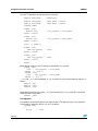
Table 1 describes the different abbreviations used in this document.
Table 1.
List of acronyms
Acronym
1.2
Peripheral / Unit
ADC12
12-bit Analog to Digital Converter
APB
Advanced Peripheral Bus bridges
BSPI
Buffered Serial Peripheral Interface
CAN
Controller Area Network
TIM
Timer
EIC
Enhanced Interrupt Controller
XTI
External Interrupts
EMI
External Memory Interface
FLASH
Embedded Flash
GPIO
General Purpose Input Output
I2C
Inter-Integrated Circuit
PCU
Power Control Unit
RCCU
Reset & Clock Control Unit
RTC
Real Time Clock
UART
Universal Asynchronous Receiver Transmitter
USB
Universal Serial Bus
WDG
Watchdog Timer
Styles and symbols
The firmware library uses the following style conventions:
●
Program listings, program examples, structure definitions and function prototypes are
shown in a special typeface. This example is a function prototype shown in courier
typeface.
int PPP_Config (int * pPointer);
●
Program portions, variables and function names quoted in a paragraph are in italic
typeface. For example
bVariable is used as local variable in the function PPP_Config.
●
6/229
A comment in a program listing is shown in italic typeface. For example:
int PPP_Config (int * pPointer); /*this is a comment */
UM0097
1.3
Document and library rules
Naming conventions
The Firmware Library uses the following naming conventions:
1.4
●
PPP is used to reference to any peripheral acronym, e.g. ADC. See the section above
for more information on peripheral acronyms.
●
System and source/header file names must be preceded by ‘71x_’, e.g. 71x_conf.h,
except driver source code and header files for PPP peripheral, e.g. 71x_tim.h. Only
lower case letters, digits, underscore and at most one suffix are allowed in filenames.
●
Constants used in one file are defined at the head of that file. A constant used in more
than one file should be defined in a header file. All constants use upper case
characters.
●
Registers are considered as constants. Their names are in upper case letters and have
in most case the same acronyms as in the STR71x reference manual document.
●
Variable names are preceded with a letter which indicates the type/size of the variable
(b:8 bits, w: 16 bits, d: 32 bits, p: pointer). The variables are in lower case and each
word begins with an upper case, e.g. bVariable, pPointer.
●
Peripheral function names are preceded with the corresponding peripheral acronym in
upper case followed by an underscore. The first letter in each word is upper case, e.g.
EIC_CurrentIRQChannelValue. Only one underscore is allowed in a function name to
separate the peripheral acronym from the rest of the function name.
●
Functions declared locally don’t have any prefix.
●
Functions used to initialize a peripheral are named PPP_Init, e.g. PCU_Init.
●
Functions for checking whether the specified PPP flag is set or not end with status, e.g.
TIM_FlagStatus.
●
Functions used to configure a peripheral functionality end with config, e.g.
WDG_PrescalerConfig. Functions that configure a peripheral interrupt are called
PPP_ITConfig.
●
Functions performing a specific action have a name that ends with a verb describing
that action, e.g. activate, clear, send, write...
●
Functions clearing specific peripheral flags are called PPP_FlagClear.
C coding rules
The following rules are used in the Firmware Library.
●
12 generic types are defined for variables whose type and size are fixed, and are
typically used for register access. These types are defined in the file 71x_type.h:
typedef unsigned long
u32;
typedef unsigned short u16;
typedef unsigned char
u8;
typedef signed long
s32;
typedef signed short s16;
typedef signed char
s8;
typedef volatile unsigned long
vu32;
typedef volatile unsigned short vu16;
typedef volatile unsigned char
vu8;
7/229
Document and library rules
UM0097
typedef volatile signed long
vs32;
typedef volatile signed short vs16;
typedef volatile signed char
vs8;
●
bool type is defined in the file 71x_type.h as:
typedef enum
{
FALSE = 0,
TRUE = !FALSE
} bool;
●
FlagStatus type is defined in the file 71x_type.h. Two values can be assigned to this
variable: SET or RESET.
typedef enum
{
RESET = 0,
SET
= !RESET
} FlagStatus;
●
FunctionalState type is defined in the file 71x_type.h. Two values can be assigned to
this variable: ENABLE or DISABLE.
typedef enum
{
DISABLE = 0,
ENABLE = !DISABLE
} FunctionalState;
●
Pointers to peripherals are used to access the peripheral control registers. Peripheral
pointers point to data structures that represent the mapping of the peripheral control
registers. A structure should be defined for each peripheral in 71x_map.h file. The
example below illustrates the GPIO register structure declaration:
typedef volatile struct
{
vu16 PC0;
vu16 EMPTY1;
vu16 PC1;
vu16 EMPTY2;
vu16 PC2;
vu16 EMPTY3;
vu16 PD;
} GPIO_TypeDef;
Register names are the register acronyms written in upper case for each peripheral.
EMPTYi (i is an integer that indexes the reserved field) replaces a reserved field and is
never used.
Sometimes an enumeration is needed for a peripheral. This enumeration is called
PPP_Registers and is declared in the file 71x_ppp.h, e.g.:
typedef enum
{
GPIO_PC0 = 0x00,
GPIO_PC1 = 0x04,
GPIO_PC2 = 0x08,
GPIO_PD = 0x0C,
} GPIO_Registers;
8/229
UM0097
Document and library rules
Peripherals are declared in 71x_map.h file. This example shows the declaration of the
GPIO peripheral:
#ifndef EXT
#define EXT extern
#endif
...
/* APB2 Base Address definition */
#define APB2_BASE 0xE0000000
#define GPIO0_BASE
#define GPIO1_BASE
(APB2_BASE + 0x3000)
(APB2_BASE + 0x4000)
/* GPIO0 and GPIO1 peripherals declaration */
#ifndef DEBUG
...
#ifdef _GPIO0
#define GPIO0
#endif /*GPIO0*/
#ifdef _GPIO1
#define GPIO1
#endif /*GPIO1*/
...
#else /* DEBUG */
((GPIO_TypeDef *)GPIO0_BASE)
((GPIO_TypeDef *)GPIO1_BASE)
#ifdef _GPIO0
EXT GPIO_TypeDef
#endif /*GPIO0*/
*GPIO0;
#ifdef _GPIO1
EXT GPIO_TypeDef
#endif /*GPIO1*/
*GPIO1;
...
#endif
/* DEBUG */
To enter debug mode you have to define the label DEBUG in 71X_conf.h file. Debug mode
allows you to watch the peripheral registers in a debugger window, but it uses up some
additional memory space and makes the code less efficient. In both cases GPIO0 is a
pointer to the first address of GPIO0 port.
EXT variable is defined in the file 71x_lib.c as follows:
#define EXT
DEBUG mode is initialized as follows in the 71x_lib.c file:
#define DEBUG
#ifdef DEBUG
void debug(void)
{
#ifdef _GPIO0
GPIO0 = (GPIO_TypeDef *)GPIO0_BASE;
#endif
9/229
Document and library rules
UM0097
#ifdef _GPIO1
GPIO1 = (GPIO_TypeDef *)GPIO1_BASE;
#endif
#ifdef _GPIO2
GPIO2 = (GPIO_TypeDef *)GPIO2_BASE;
#endif
...
}
#endif /* DEBUG */
Note:
Debug mode increases the code size and reduces the code performance. For this reason, it
is recommended to use it only when debugging the application and to remove it from the
final application code.
Each peripheral has several dedicated registers which contain different flags. Registers are
defined within a dedicated structure for each peripheral. Flag definition is adapted to each
peripheral case (defined in 71x_ppp.h file). Flags are defined as acronyms written in upper
case and prefixed by ‘PPP_’ prefix, PPP is the acronym of the corresponding peripheral.
The flags of each peripheral are included in an enumeration named PPP_Flags. Some
peripherals adopt this naming convention.
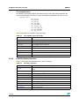
Each flag label is defined as a byte divided into two parts:
–
The 3 MSB bits are allocated to identify the register to which the flag belongs (it is
possible to number registers from 0 to 7).
–
The 5 LSB bits are allocated to identify the flag position in the register to which it
belongs (it is possible to number flags from 0 to 31).
Bit 7
Bit 6
Bit 5
Bit 4
Bit 3
Register
The following gives an example of flag definitions:
typedef enum
{
APB_APBT = 0x26,
APB_OUTM = 0x25,
APB_ABORT = 0x21,
APB_ABTEN = 0x49,
APB_OMnRW = 0x68,
APB_TOnRW = 0x88
} APB_Flags;
10/229
Bit 2
Bit position
Bit 1
Bit 0
UM0097
Firmware library
2
Firmware library
2.1
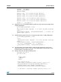
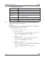
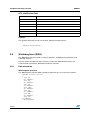
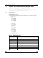
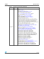
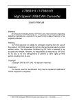
Package description
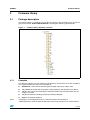
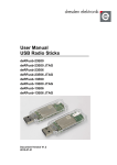
The firmware library is supplied in one single zip package. The extraction of the zip file will
give the one folder "STR71xFWLib\\FWLib" containing the following sub-directories:
Figure 1.
2.1.1
Firmware library directory structure
Examples
This directory contains for each peripheral sub-directory, the minimum set of files needed to
run a typical example on how to use a peripheral:
Note:
●
Readme.txt: a brief text file describing the example and how to make it work
●
71x_conf.h: the header file to configure used peripherals and miscellaneous defines
●
71x_it.c: the source file containing the interrupt handlers (the function bodies may be
empty if not used)
●
71x_it.h: header file including all interrupt handler prototypes
●
main.c: the example program
All examples are independent from any software toolchain and running on
STMicroelectronics STR71x-EVAL board and can be easily tailored to any other hardware.
11/229
Firmware library
2.1.2
UM0097
Library
This directory contains all the subdirectories and files that form the core of the library:
●
●
inc sub-directory contains the firmware library header files that do not need to be
modified by the user:
–
71x_type.h: Contains the common data types and enumeration used in all other
files
–
71x_map.h: Contains the peripherals memory mapping and registers data
structures
–
71x_lib.h: Main header file including all other headers
–
71x_ppp.h (one header file per peripheral): contains the function prototypes, data
structures and enumeration
src sub-directory contains the firmware library source files that do not need to be
modified by the user:
–
71x_ppp.c (one source file per peripheral): contains the function bodies of each
peripheral
Note:
All library files are coded in Strict ANSI-C and are independent from any firmware toolchain.
2.1.3
Project
This directory contains a standard template project program that compiles all library files
and also all the user modifiable files needed to create a new project:
2.2
●
71x_conf.h: The configuration header file with all peripherals defined by default
●
71x_it.c: The source file containing the interrupt handlers (the function bodies are
empty in this template)
●
71x_it.h: header file including all interrupt handlers prototypes
●
main.c: The main program body
●
EWARM, RVDK, RVMDK, RIDE: For each toolchain usage, refer to Readme.txt file
available in the same sub-directory
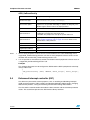
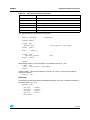
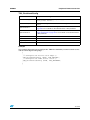
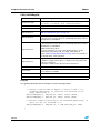
File description
Several files are used in the firmware library. Table 2 enumerates and describes the different
files used in the firmware library.
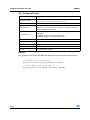
Table 2.
Source/header file list
Filename
71x_conf.h
main.c
12/229
Description
Parameter configuration file. It should be modified by the user to specify several
parameters to interface with the library before running any application.
You can enable or disable peripherals if you use the template and you can
also change the value of your external crystal oscillator value.
Using this file you can select to compile the library in DEBUG or RELEASE mode.
The main example program body.
UM0097
Firmware library
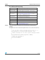
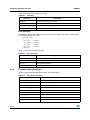
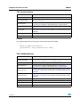
Table 2.
Source/header file list (continued)
Filename
Description
71x_it.c
Peripheral interrupt functions file. It is modified by you by including the interrupt
functions code used in your application. In case of multiple interrupt requests mapped
on the same interrupt vector, the function performs a polling on interrupt flags
contained inside the peripheral in order to establish the exact source of the interrupt.
The names of these functions are already provided in the firmware library.
71x_it.h
Header file including the definition of interrupt functions.
71x_lib.c
Debug mode initialization file. It includes the definition of variable pointers pointing
each one to the first address of the dedicated peripheral and the definition of one
function called when you choose to enter in debug mode. This function initializes the
defined pointers.
71x_lib.h
Header file including all the peripherals’ header files. It is the unique file to be included
in the user application to interface with the library.
71x_map.h
This file implements memory mapping and physical registers address definition for
both development and debug modes. This file is supplied with all peripherals.
71x_type.h
Common declarations file. It includes common types and constants which are used by
all peripheral drivers.
71x_ppp.c
Driver source code file of the PPP peripheral written in C language.
71x_ppp.h
Header file of the PPP peripheral. It includes the functions prototypes, data structures
and enumerations used by the driver and also available for the user.
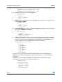
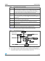
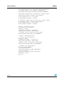
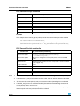
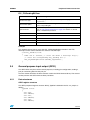
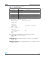
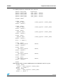
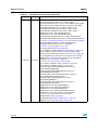
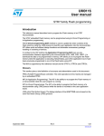
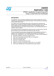
Figure 2 shows the firmware library architecture and file inclusion relationships.
Figure 2.
Firmware library file structure
application.c
Application Layer
71x_conf.h
71x_it.c
71x_lib.h
Software Layer
71x_map.h
71x_type.h
ppp.h
71x_lib.c
71x_it.h
ppp.c
Hardware Layer
Peripheral X
For each peripheral a source code file 71x_ppp.c and a header file 71x_ppp.h are provided.
●
the 71x_ppp.c file contains all the firmware functions required to use the peripheral
●
the 71x_ppp.h file contains all the functions prototypes, data structures, data types and
enumeration needed. It contains also the inline functions code, if any.
13/229
Firmware library
UM0097
One memory mapping file 71x_map.h is supplied for all peripherals. This file contains all the
register declarations for both development and debug modes.
The header file 71x_lib.h includes all the peripheral header files. This is the only file that has
to be included in the user application to interface with the library.
You can modify the 71x_conf.h to define which peripherals need to be included in the
application to make it run.
Other files are also provided: 71x_it.h and 71x_it.c. These files contain all the firmware
functions required to handle the STR71x interrupts.
If you want to handle an interrupt routine, you should modify the appropriate function in the
file 71x_it.c (the body of each function is empty by default).
Note:
Only the 71x_conf.h and 71x_it.c files should be modified to link the application with the
library.
2.3
How to use the STR71x library
This section describes how to implement an application using the STR71x firmware library.
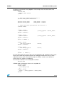
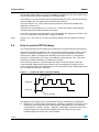
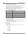
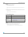
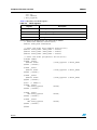
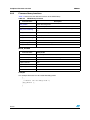
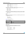
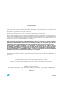
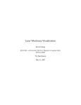
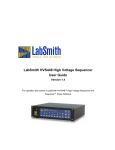
Example: The application initializes and starts two timer overflow interrupts. When a timer
expires, an interrupt, handled in 71x_it.c, is generated. Timer 0 generates an overflow
interrupt every 130 ms and toggles the GPIO0 pin level on/off. Timer 1 is configured to
generate an interrupt every 2.1s and to set GPIO1 pin to high level for 1.05 s. The chip is
clocked by an external oscillator at a frequency of 16 MHz.
Timer 0 interrupt priority is set to be higher than Timer 1 interrupt priority to allow the
Timer 0 T0TIMI_IRQHandler interrupt routine to be served during the execution of the
Timer 1 interrupt routine. The following figure shows the behavior of the GPIO0 and GPIO1
pins and Timer 0 and Timer 1 interrupts.
Figure 3.
Timer0 and Timer1 interrupt handling
Timer0 interrupt
GPIO0 pin
GPIO1 pin
Timer1 interrupt
The following steps explain how to use the STR71x library to build the user application
●
14/229
Edit the 71x_conf.h file and uncomment the _GPIO and _TIM labels, this allows you to
include the firmware libraries of the GPIO and the TIM peripherals in your firmware.
Uncomment the _GPIO0, _GPIO1, _TIM0 and _TIM1 labels to be able to access the
peripheral registers. Uncomment the DEBUG label, this allows you to see the
peripheral registers content in the watch window.
UM0097
Firmware library
#ifndef __71x_CONF_H
#define __71x_CONF_H
#define DEBUG
...
#define _TIM /*to include the TIM library*/
#define _TIM0 /*to access the TIM0 registers*/
#define _TIM1 /*to access the TIM1 registers*/
...
#define _GPIO /*to include the GPIO library*/
#define _GPIO0 /*to access the GPIO0 registers*/
#define _GPIO1 /*to access the GPIO1 registers*/
...
#endif /* __71x_CONF_H */
●
Edit the file 71x_it.c and add the following code to the Timer 0 interrupt handler routine
T0TIMI_IRQHandler:
void T0TIMI_IRQHandler (void)
{
TIM_FlagClear(TIM0, TIM_TOF); /* to clear the TIM0 interrupt
flag */
GPIO_WordWrite(GPIO0, ~GPIO_WordRead(GPIO0)); /* invert the
GPIO0 output level */
}
●
Add the following code to the Timer 1 interrupt handler routine T1TIMI_IRQHandler:
void T1TIMI_IRQHandler (void)
{
u32 i;
TIM_FlagClear(TIM1, TIM_TOF); /*to clear the TIM1 interrupt
flag */
GPIO_WordWrite(GPIO1, ~GPIO_WordRead(GPIO1));
for (i=0; i<0x000FFFFF; i++); /* delay */
GPIO_WordWrite(GPIO1, ~GPIO_WordRead(GPIO1));
}
●
The initialization of the GPIO0, GPIO1, TIM0 and TIM1 peripherals is done in the
application source file, main.c in our case. The configuration of the EIC and the IRQ
channels priority is also done in this file.
●
Edit the main.c file and add the following code:
#include “71x_lib.h“
int main(void)
{
#ifdef DEBUG
debug();
#endif
/*EIC configuration*/
/*Set Timer 0 interrupt channel priority level to 2*/
EIC_IRQChannelPriorityConfig(T0TIMI_IRQChannel,2);
/*Enable Timer 0 IRQ channel interrupts*/
EIC_IRQChannelConfig(T0TIMI_IRQChannel,ENABLE);
/* Set Timer 1 interrupt channel priority level to 1*/
15/229
Firmware library
UM0097
EIC_IRQChannelPriorityConfig(T1TIMI_IRQChannel,1);
/* Enable Timer 1 IRQ channel interrupts*/
EIC_IRQChannelConfig(T1TIMI_IRQChannel,ENABLE);
/*configure GPIO0 pins as push-pull output mode*/
GPIO_Config(GPIO0, 0xFFFF, GPIO_OUT_PP);
/* Set GPIO0 pins to low level*/
GPIO_WordWrite(GPIO0, 0x0000);
/* configure GPIO1 pins as push-pull output mode*/
GPIO_Config(GPIO1, 0xFFFF, GPIO_OUT_PP);
/* Set GPIO1 pins to low level*/
GPIO_WordWrite(GPIO1, 0x0000);
/*Timer 0 Configuration*/
//*Initialize the Timer*/
TIM_Init (TIM0);
/*Configure Timer 0 Prescaler*/
TIM_PrescalerConfig (TIM0,0x0F);
/* Enable Timer 0 Overflow Interrupt*/
TIM_ITConfig(TIM0,TIM_TO_IT,ENABLE);
/* Timer 1 Configuration*/
/* Initialize the Timer*/
TIM_Init (TIM1);
/* Configure Timer 1 Prescaler*/
TIM_PrescalerConfig (TIM1,0xFF);
/* Enable Timer 1 Overflow Interrupt*/
TIM_ITConfig(TIM1,TIM_TO_IT,ENABLE);
/* Enable IRQ interrupts*/
EIC_IRQConfig(ENABLE);
/* Start Timer 0*/
TIM_CounterConfig (TIM0,TIM_START);
/* Start Timer 1*/
TIM_CounterConfig (TIM1,TIM_START);
/*Infinite loop*/
while(1);
}
16/229
UM0097
3
Peripheral firmware overview
Peripheral firmware overview
This chapter describes in detail each peripheral firmware library. The related functions are
fully documented. An example of use of the function is given and some important
considerations to take into account to avoid failure are also provided.
This chapter describes each peripheral firmware library in detail. The related functions are
fully documented. An example of use of the function is given and some important
considerations to take into account to avoid failure are also provided.
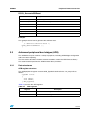
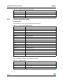
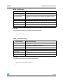
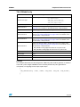
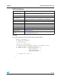
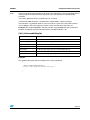
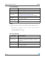
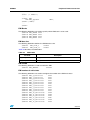
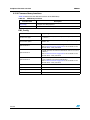
Table 3 describes peripheral firmware functions.
Table 3.
Peripheral firmware functions
Function name
3.1
Description
Function prototype
Prototype declaration
Behavior Description
Brief explanation of how the functions are executed
Input Parameter {x}
Description of the input parameters
Output parameter {x}
Description of the output parameters
Return Value
Value returned by the function
Required Preconditions
Conditions required before calling the function
Called Functions
Other library functions called by the function
See also
Related functions for reference
Power control unit (PCU)
The PCU driver may be used for a variety of purposes, including power management
configuration and low power mode selection.
The first section describes the data structures used in the PCU firmware library. The second
section presents the PCU firmware library functions.
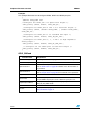
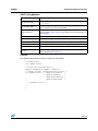
3.1.1
Data structures
PCU register structure
The PCU register structure PCU_TypeDef is defined in the 71x_map.h file as follows:
typedef volatile struct
{
vu16 MDIVR;
u16 EMPTY1;
vu16 PDIVR;
u16 EMPTY2;
vu16 RSTR;
u16 EMPTY3;
vu16 PLL2CR;
u16 EMPTY4;
vu16 BOOTCR;
u16 EMPTY5;
17/229
Peripheral firmware overview
UM0097
vu16 PWRCR;
u16 EMPTY6;
} PCU_TypeDef;
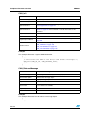
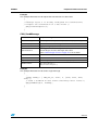
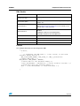
Table 4 describes the PCU structure fields:
Table 4.
PCU structure fields
Register
Description
MDIVR
CPU frequency division factor
PDIVR
APB frequency division factor
RSTR
Peripheral Reset Control Register
PLL2CR
PLL2 Control Register
BOOTCR
Boot Configuration Register
PWRCR
Power Control Register
The PCU peripheral is declared in the same file:
...
#define PCU_BASE
0xA0000040
...
#ifndef DEBUG
...
#ifdef _PCU
#define PCU
((PCU_TypeDef *)PCU_BASE)
#endif /*PCU*/
...
#else
/* DEBUG */
...
#ifdef _PCU
EXT PCU_TypeDef
*PCU;
#endif /*PCU*/
...
#endif
When debug mode is used, PCU pointer is initialized in the file 71x_lib.c:
#ifdef _PCU
#define PCU
((PCU_TypeDef *)PCU_BASE)
#endif /*PCU*/
In debug mode, _PCU must be defined, in the file 71x_conf.h, to access the peripheral
registers as follows:
#define _PCU
Some PCU functions use the RCCU and the XTI registers and functions, _RCCU and _XTI
must be defined in 71x_conf.h file to make the RCCU and the XTI functions accessible:
#define _RCCU
#define _XTI
18/229
UM0097
Peripheral firmware overview
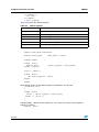
Voltage regulator status
The following enumeration defines the states of the voltage regulator. The VR_Status
enumeration is defined in the file 71x_pcu.h:
typedef enum
{
PCU_STABLE,
PCU_UNSTABLE
} PCU_VR_Status;
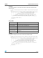
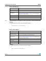
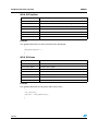
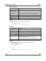
Table 5 describes the status of PCU voltage regulator.
Table 5.
PCU voltage regulator status
Regulator State
Description
PCU_STABLE
The Main Voltage Regulator is stable and can be used to power the device.
PCU_UNSTABLE
The Main Voltage Regulator is not yet stable
PCU voltage regulators
The following enumeration defines the power control unit voltage regulators. The PCU_VR
enumeration is declared in the file 71x_pcu.h:
typedef enum
{
PCU_MVR = 0x0008,
PCU_LPR = 0x0010
} PCU_VR;
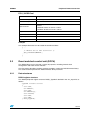
Table 6 describes the PCU voltage regulators.
Table 6.
PCU voltage regulator descriptions
Voltage Regulators
Description
PCU_MVR
The Main Voltage Regulator
PCU_LPR
The Low Power Voltage Regulator
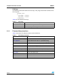
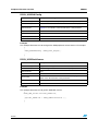
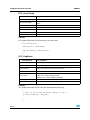
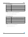
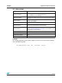
WFI clocks
The following enumeration defines the WFI mode clocks. WFI_CLOCKS enumeration is
declared in the file 71x_pcu.h:
typedef enum
{
WFI_CLOCK2_16,
WFI_Ck_AF
} WFI_CLOCKS;
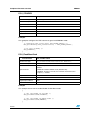
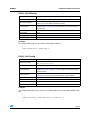
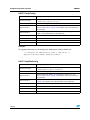
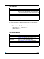
Table 7 lists the different WFI Clocks.
Table 7.
WFI clocks
WFI Clocks
Description
WFI_CLOCK2_16
CLOCK2/16 clock is selected during LPWFI
WFI_Ck_AF
The RTC clock is selected during LPWFI
19/229
Peripheral firmware overview
UM0097
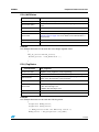
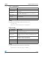
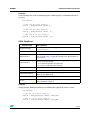
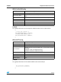
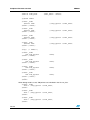
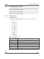
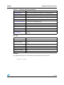
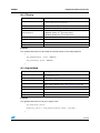
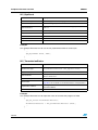
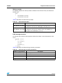
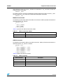
PCU flags
The following enumeration defines the PCU flags. PCU_Flags enumeration is defined in the
file 71x_pcu.h:
typedef enum
{
PCU_WREN = 0x8000,
PCU_VROK = 0x1000
} PCU_Flags;
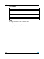
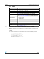
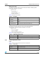
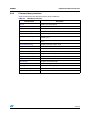
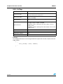
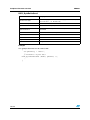
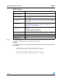
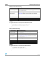
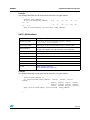
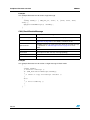
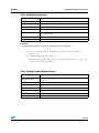
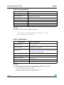
Table 8 lists the different PCU flags.
Table 8.
PCU flags
PCU Flags
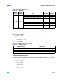
3.1.2
Description
PCU_WREN
Power Control Unit register Write Enable flag
PCU_VROK
Main Voltage Regulator OK flag
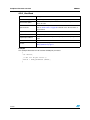
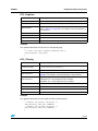
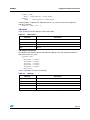
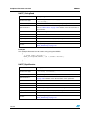
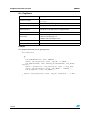
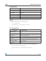
Firmware library functions
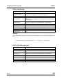
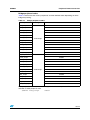
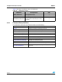
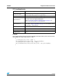
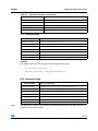
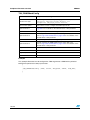
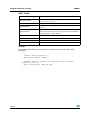
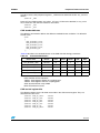
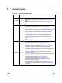
Table 9 enumerates the different functions of the PCU library.
Table 9.
PCU library functions
Function Name
20/229
Description
PCU_MVRStatus
Reads and returns the PCU main voltage regulator status
PCU_FlagStatus
Reads and returns the status of a specified PCU flag
PCU_VRConfig
Configures (Enables / Disables) the PCU voltage regulators
PCU_VRStatus
Reads and returns the PCU voltage regulator status
PCU_LVDDisable
Disables the Low Voltage Detector
PCU_LVDStatus
Reads and returns the LVD status
PCU_LPModesConfig
Configures the different STR71x low power mode options
PCU_WFI
Used to enter WFI and LPWFI modes
PCU_STOP
Used to enter STOP mode
PCU_STANDBY
Used to enter STANDBY mode
PCU_FlashBurstCmd
This routine is used to set the FLASH to LP/BURST mode
PCU_32OSCCmd
This routine is used to enable/disable the 32 kHz oscillator
UM0097
Peripheral firmware overview
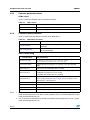
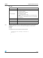
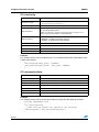
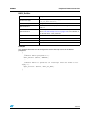
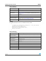
PCU_MVRStatus
Function Name
PCU_MVRStatus
Function Prototype
PCU_VR_Status PCU_MVRStatus (void);
Behavior Description
This routine checks and returns the main voltage regulator stability
status.
Input Parameter
None
Output Parameter
None
Return Value
The stability status of the Main Voltage Regulator. Refer to Voltage
regulator status on page 19 for more details on the allowed values of
this parameter.
Required preconditions
None
Called Functions
None
Example:
This example illustrates how to check the main voltage regulator status:
{
...
PCU_VR_Status MainVR_Status;
MainVR_Status = PCU_MVRStatus ();
...
}
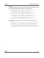
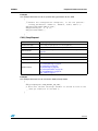
PCU_FlagStatus
Function Name
PCU_FlagStatus
Function Prototype
FlagStatus PCU_FlagStatus (PCU_Flags Xflag);
Behavior Description
This routine is used to check the status of the specified PCU flag.
Input Parameter
Xflag: specifies the PCU flag. Refer to PCU flags on page 20 for more
details on the allowed values of this parameter.
Output Parameter
None
Return Value
The specified flag status:
– SET: The PCU flag is set.
– RESET: The PCU flag is reset.
Required preconditions
None
Called Functions
None
Example:
This example illustrates how to check the PCU flag status.
{
FlagStatus WREN_Status;
FlagStatus VROK_Status;
..
/* WREN_Status holds the WEN flag status */
WREN_Status = PCU_FlagStatus (PCU_WREN);
21/229
Peripheral firmware overview
UM0097
/* VROK_Status holds the Main VR_OK flag status */
VROK_Status = PCU_FlagStatus (PCU_VROK);
...
}
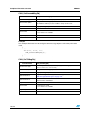
PCU_VRConfig
Function Name
PCU_VRConfig
Function Prototype
void PCU_VRConfig(PCU_VR Xvr, FunctionalState
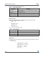
NewState);
Behavior Description
This routine is used to configure (enable / bypass) the PCU voltage
regulators.
Input Parameter 1
Xvr: Specifies the PCU voltage regulator.
Refer to PCU voltage regulators on page 19 for more details on the
allowed values of this parameter.
Input Parameter 2
NewState: Specifies whatever the corresponding voltage regulator is
enabled or bypassed.
– ENABLE: Enable the corresponding PCU voltage regulator
– DISABLE: Bypass the corresponding PCU voltage regulator
Output Parameter
None
Return Value
None
Required preconditions
None
Called Functions
None
Example:
This example illustrates how to bypass the main voltage regulator.
{
...
PCU_VRConfig(PCU_MVR, DISABLE);
...
}
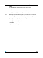
PCU_LVDDisable
Function Name
22/229
PCU_LVDDisable
Function Prototype
void PCU_LVDDisable (void);
Behavior Description
This routine is used to disable the Low Voltage Detector.
Input Parameter
None
Output Parameter
None
Return Value
None
Required preconditions
None
Called Functions
None
UM0097
Peripheral firmware overview
Example:
This example illustrates how to disable the LVD feature.
{
...
PCU_LVDDisable ();
...
}
PCU_VRStatus
Function Name
PCU_VRStatus
Function Prototype
FunctionalState PCU_VRStatus (PCU_VR xVR);
Behavior Description
This routine gets the PCU voltage regulator status.
Input Parameter
xVR: specifies the PCU voltage regulator.
Refer to PCU voltage regulators on page 19 for more details on the
allowed values of this parameter.
Output Parameter
None
Return Value
The state of the specified voltage regulator.
– ENABLE: The voltage regulator is enabled.
– DISABLE: The voltage regulator is bypassed.
Required preconditions
None
Called Functions
None
Example:
This example illustrates how to check the PCU voltage regulator status.
{
FlagStatus MVR_Status;
FlagStatus LPVR_Status;
...
MVR_Status = PCU_VRStatus (PCU_MVR);
LPVR_Status = PCU_VRStatus (PCU_LPR);
...
}
23/229
Peripheral firmware overview
UM0097
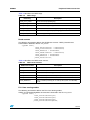
PCU_LVDStatus
Function Name
PCU_LVDStatus
Function Prototype
FunctionalState PCU_LVDStatus (void);
Behavior Description
This routine gets and returns the LVD status.
Input Parameter
None
Output Parameter
None
Return Value
The LVD status.
– ENABLE: the LVD is enabled
– DISABLE: .
Required preconditions
None
Called Functions
None
Example:
This example illustrates how to check the LVD feature status.
{
...
FunctionalState LVD_Status;
LVD_Status = PCU_LVDStatus ();
...
}
24/229
UM0097
Peripheral firmware overview
PCU_LPModesConfig
Function Name
PCU_LPModesConfig
Function Prototype
void PCU_LPModesConfig (FunctionalState PLL1_State,
FunctionalState MVR_State,FunctionalState
FLASH_State, FunctionalState
LPWFI_State,LPWFI_Clock_Typedef LPWFI_Clock);
Behavior Description
This routine configures the different STR71x low power mode options.
Input Parameter 1
PLL1_State: the state of PLL1 when CK_AF selected.
– ENABLE: PLL1 is not disabled when CK_AF is selected
– DISABLE: PLL1 is disabled automatically when CK_AF is selected as
system clock
Input Parameter 2
MVR_State: the state of the Main Voltage Regulator when CK_AF is
selected.
– ENABLE: MVREG is enabled during LPWFI and STOP modes
– DISABLE: MVREG is disabled during LPWFI and STOP modes
Input Parameter 3
FLASH_State: the state of the flash during LPWFI and STOP modes.
– ENABLE: Flash Stand-by mode during LPWFI and STOP modes
– DISABLE: FLASH in powerdown during LPWFI and STOP modes
Input Parameter 4
LPWFI_State: the state of low power mode during LPWFI.
– ENABLE: Enable Low power mode during WFI mode
– DISABLE: Disable Low power mode disabled during WFI mode
Input Parameter 5
LPWFI_Clock: the selected clock during LPWFI.
– LPWFI_CLK2_16: CLK2/16 is selected during LPWFI
– LPWFI_CK_AF: CK_AF is selected during LPWFI
Output Parameter
None
Return Value
None
Required preconditions
None
Called Functions
None
Example:
This example disables the PLL1 automatically when CK_AF is selected is selected as
source clock, puts the FLASH in PWD mode, disables the MVR during STOP and WFI
mode, enables low power mode during WFI mode (LPWI) and selects CK_AF as source
clock during LPWFI mode.
{
/* User code */
/* Set the MVR disabled and the FLASH in PWD mode during STOP
mode */
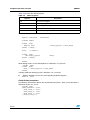
PCU_LPModesConfig(DISABLE,DISABLE,DISABLE,ENABLE,LPWFI_CK_AF);
/*
|
|
|
|
|_CK_AF is selected during LPWFI
|
|
|
|_Enable Low power mode during WFI mode
|
|
|_FLASH in powerdown during LPWFI and STOP modes
|
|_MVREG is disabled during LPWFI and STOP modes
|_PLL1 is disabled automatically when CK_AF is selected */
/* User code */
25/229
Peripheral firmware overview
UM0097
/* Go into STOP mode */
PCU_STOP();
/* User code */
/* Go into LPWFI mode */
PCU_WFI();
/* User code */
}
}
PCU_WFI
Function Name
PCU_WFI
Function Prototype
void PCU_WFI (void);
Behavior Description
This routine is used to enter WFI and LPWFI modes
Input Parameter
None
Output Parameter
None
Return Value
None
Required preconditions
PCU_LPModesConfig function should be called to configure the WFI
mode options
Called Functions
None
Example 1:
This example configures WFI mode.
{
/* Go into LPWFI mode */
PCU_WFI();
}
Example 2:
This example configures LP_WFI mode with FLASH in PWD mode and MVR disabled,
RCLK = CLK2_16
{
/*Set the MVR disabled and the FLASH in PWD mode during LP_WFI
mode */
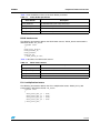
PCU_LPModesConfig(DISABLE,DISABLE,DISABLE,ENABLE,LPWFI_CLK2_16)
;
/*
|
|
|
|
|_CLK2/16 selected during LPWFI
|
|
|
|_Enable low power mode during WFI mode
|
|
|_FLASH in powerdown during LPWFI and STOP modes
|
|_MVREG is disabled during LPWFI and STOP modes
|_PLL1 is disabled automatically when CK_AF is selected */
/* Enter LPWFI mode */
PCU_WFI();
}
26/229
UM0097
Peripheral firmware overview
Example 3:
This example configures LP_WFI mode with FLASH in PWD mode and MVR disabled,
RCLK = CK_AF,
{
/*Set the MVR disabled and the FLASH in PWD mode during LP_WFI
mode */
PCU_LPModesConfig(DISABLE,DISABLE,DISABLE,ENABLE,LPWFI_CK_AF);
/*
|
|
|
|
|_CK_AF is selected during LPWFI
|
|
|
|_Enable Low power mode during WFI mode
|
|
|_FLASH in powerdown during LPWFI and STOP modes
|
|_MVREG is disabled during LPWFI and STOP modes
|_PLL1 is disabled automatically when CK_AF is selected */
/* Go into LPWFI mode */
PCU_WFI();
}
PCU_STOP
Function Name
PCU_STOP
Function Prototype
void PCU_WFI (void);
Behavior Description
This routine is used to enter STOP mode.
Input Parameter
None
Output Parameter
None
Return Value
None
Required preconditions
PCU_LPModesConfig function should be called to configure the STOP
mode options
Called Functions
None
Example:
This example configures STOP FLASH in PWD mode and MVR disabled.
{
/*Set the MVR disabled and the FLASH in PWD mode during STOP
mode. */
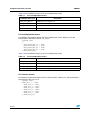
PCU_LPModesConfig(DISABLE,DISABLE,DISABLE,ENABLE,LPWFI_CK_AF);
/*
|
|
|
|
|_CK_AF is selected during LPWFI
|
|
|
|_Enable Low power mode during WFI mode
|
|
|_FLASH in powerdown during LPWFI and STOP modes
|
|_MVREG is disabled during LPWFI and STOP modes
|_PLL1 is disabled automatically when CK_AF is selected */
/*Go into STOP mode
PCU_STOP()
*/
}
27/229
Peripheral firmware overview
UM0097
PCU_STANDBY
Function Name
PCU_STANDBY
Function Prototype
void PCU_STANDBY (void);
Behavior Description
This routine is used to enter STANDBY mode
Input Parameter
None
Output Parameter
None
Return Value
None
Required preconditions
None
Called Functions
None
Example:
This examples configures the RTC alarm then goes into STANDBY mode
{
/* Configure RTC alarm after RTC_ALARM_DELAY s */
RTC_AlarmConfig(RTC_CounterValue() + RTC_ALARM_DELAY);
/* Go into Standby */
PCU_STANDBY();
}
PCU_FlashBurstCmd
Function Name
PCU_FlashBurstCmd
Function Prototype
PCU_FlashBurstCmd(FunctionalState NewState);
Behavior Description
This routine is used to set the FLASH to LP/BURST mode
Input Parameter
NewStatus: specifies whether the FLASH BURST mode is enabled or
disabled.
– ENABLE: FLASH in BURST mode (default mode)
– DISABLE: FLASH in LP mode, the maximum allowed execution
frequency = 33 MHz
Output Parameter
None
Return Value
None
Required preconditions
None
Called Functions
None
Example:
This example shows how to enable/disable FLASH Burst mode.
{
/* Set the FLASH in LP mode */
PCU_FlashBurstCmd(DISABLE);
/* Set the FLASH in BURST mode */
PCU_FlashBurstCmd(ENABLE);
}
28/229
UM0097
Peripheral firmware overview
PCU_32OSCCmd
Function Name
PCU_32OSCCmd
Function Prototype
void PCU_32OSCCmd (FunctionalState NewState)
Behavior Description
Enables or disables the 32 kHz oscillator
Input Parameter
NewState: specifies whether the 32 kHz oscillator is enabled or
disabled.
– ENABLE: enables the 32 kHz oscillator.
– DISABLE: disables the 32 kHz oscillator.
Output Parameter
None
Return Value
None
Required preconditions
None
Called Functions
None
Example:
This example illustrates how to enable the 32 kHz oscillator.
{ ...
/* Enable the 32 kHz oscillator */
PCU_32OSCCmd(ENABLE);
...
}
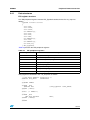
3.2
Reset and clock control unit (RCCU)
The RCCU driver may be used for a variety of purposes, including internal clock
configuration and clock source selection.
The first section describes the data structure members used in the RCCU firmware library.
The second section presents the RCCU firmware library functions.
3.2.1
Data structures
RCCU register structure
The RCCU peripheral register structure RCCU_TypeDef is defined in the 71x_map.h file as
follows:
typedef volatile struct
{
vu32 CCR;
u32 EMPTY1;
vu32 CFR;
u32 EMPTY2[3];
vu32 PLL1CR;
vu32 PER;
vu32 SMR;
} RCCU_TypeDef;
29/229
Peripheral firmware overview
UM0097
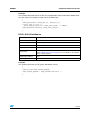
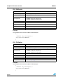
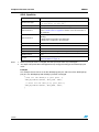
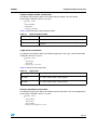
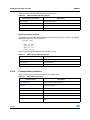
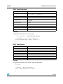
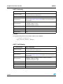
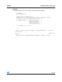
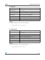
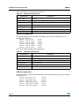
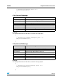
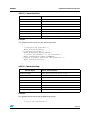
Table 10 presents the RCCU registers.
Table 10.
RCCU registers
Register
Description
CCR
Clock Control Register
CFR
Clock Flag Register
PLL1CR
PLL1 configuration Register
PER
Peripheral Clock Enable Register
SMR
System Mode Register
The RCCU peripheral is declared in the same file:
...
#define RCCU_BASE
0xA0000000
...
#ifndef DEBUG
...
#ifdef _RCCU
#define RCCU
((RCCU_TypeDef *)RCCU_BASE)
#endif /*RCCU*/
...
#else
/* DEBUG */
...
#ifdef _RCCU
EXT RCCU_TypeDef
*RCCU;
#endif /*RCCU*/
...
#endif
When debug mode is used, RCCU pointer is initialized in 71x_lib.c file:
#ifdef _RCCU
#ifdef _RCCU
RCCU = (RCCU_TypeDef *)RCCU_BASE;
#endif
In debug mode the following macro is defined in 71x_conf.h file:
●
_RCCU is defined to access the corresponding peripheral registers.
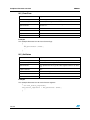
#define _RCCU
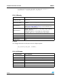
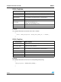
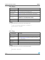
Clock divider parameters
The following enumeration defines the clock divider parameters. Clock_Div enumeration is
defined in the file 71x_rccu.h:
typedef enum
{RCCU_DEFAULT = 0x00,
RCCU_RCLK_2 = 0x01,
RCCU_RCLK_4 = 0x02,
RCCU_RCLK_8 = 0x03
} RCCU_Clock_Div;
30/229
UM0097
Peripheral firmware overview
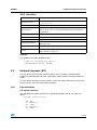
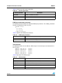
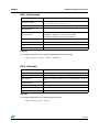
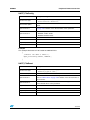
Table 11 lists the different values of the clock divider parameter.
Table 11.
Clock divider parameters
Clock Divider
Description
RCCU_DEFAULT
The default divider (reset value) division by 1
RCCU_RCLK_2
Divide the RCLK by 2
RCCU_RCLK_4
Divide the RCLK by 4
RCCU_RCLK_8
Divide the RCLK by 8
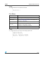
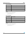
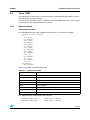
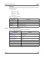
RCLK clock source
The following enumeration defines the RCLK clock sources. RCLK_Clocks enumeration is
defined in the file 71x_rccu.h:
typedef enum
{
RCCU_PLL1_Output,
RCCU_CLOCK2_16,
RCCU_CLOCK2,
RCCU_CK_AF
} RCCU_RCLK_Clocks;
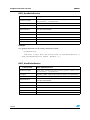
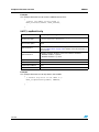
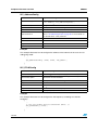
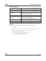
Table 12 describes the RCLK clock sources.
Table 12.
RCLK clock sources
RCLK Clock Source
Description
RCCU_PLL1_Output
Select the PLL1 output as RCLK clock source
RCCU_CLOCK2_16
Select the RCLK2/16 as RCLK clock source
RCCU_CLOCK2
Select the Clock2 as RCLK clock source
RCCU_CK_AF
Select the RTC as RCLK clock source
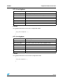
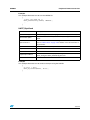
PLL1 multiplication factors
The following enumeration defines the PLL1 multiplication factors. RCCU_PLL1_Mul
enumeration is declared in the file 71x_rccu.h:
typedef enum
{
RCCU_PLL1_Mul_12 = 0x01,
RCCU_PLL1_Mul_16 = 0x03,
RCCU_PLL1_Mul_20 = 0x00,
RCCU_PLL1_Mul_24 = 0x02
} RCCU_PLL1_Mul;
31/229
Peripheral firmware overview
UM0097
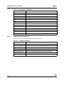
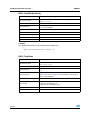
Table 13 lists the different values of the PLL1 multiplication factor.
Table 13.
PLL1 multiplication factors
PLL Multiplication factor
Description
RCCU_PLL1_Mul_12
Multiplication factor equal to 12
RCCU_PLL1_Mul_16
Multiplication factor equal to 16
RCCU_PLL1_Mul_20
Multiplication factor equal to 20
RCCU_PLL1_Mul_24
Multiplication factor equal to 24
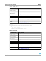
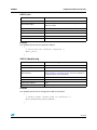
PLL2 multiplication factors
The following enumeration defines the PLL2 multiplication factors. RCCU_PLL2_Mul
enumeration is declared in the file 71x_rccu.h:
typedef enum
{
RCCU_PLL2_Mul_12 = 0x01,
RCCU_PLL2_Mul_16 = 0x03,
RCCU_PLL2_Mul_20 = 0x00,
RCCU_PLL2_Mul_28 = 0x02
} RCCU_PLL2_Mul;
Table 14 lists the different values of the PLL2 multiplication factor.
Table 14.
PLL2 multiplication factors
PLL Multiplication factor
Description
RCCU_PLL2_Mul_12
Multiplication factor equal to 12
RCCU_PLL2_Mul_16
Multiplication factor equal to 16
RCCU_PLL2_Mul_20
Multiplication factor equal to 20
RCCU_PLL2_Mul_28
Multiplication factor equal to 28
PLL division factors
The following enumeration defines the PLL division factors. RCCU_PLL_Div enumeration is
declared in the file 71x_rccu.h:
typedef enum
{RCCU_Div_1 = 0x00,
RCCU_Div_2 = 0x01,
RCCU_Div_3 = 0x02,
RCCU_Div_4 = 0x03,
RCCU_Div_5 = 0x04,
RCCU_Div_6 = 0x05,
RCCU_Div_7 = 0x06
} RCCU_PLL_Div;
32/229
UM0097
Peripheral firmware overview
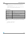
Table 15 lists the different values of the PLL division factor.
Table 15.
PLL division factors
PLL Division factor
Description
RCCU_Div_1
Division factor equal to 1
RCCU_Div_2
Division factor equal to 2
RCCU_Div_3
Division factor equal to 3
RCCU_Div_4
Division factor equal to 4
RCCU_Div_5
Division factor equal to 5
RCCU_Div_6
Division factor equal to 6
RCCU_Div_7
Division factor equal to 7
USB clock source
The following enumeration defines the USB clock sources. USB_Clocks enumeration is
defined in the file 71x_rccu.h:
typedef enum
{RCCU_PLL2_Output = 0x01,
RCCU_USBCK = 0x00
} RCCU_USB_Clocks;
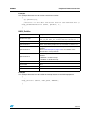
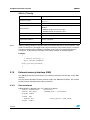
Table 16 describes the USB clock sources.
Table 16.
USB clock sources
USB Clock Source
Description
RCCU_PLL2_Output
Select the PLL2 output as USB clock source
RCCU_USBCK
Select the USBCK as USB clock source
RCCU internal clocks
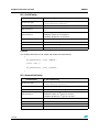
The following enumeration defines the RCCU internal clocks. RCCU_Clocks enumeration is
defined in the file 71x_rccu.h:
typedef enum
{RCCU_CLK2,
RCCU_RCLK,
RCCU_MCLK,
RCCU_PCLK2,
RCCU_PCLK1
} RCCU_Clocks;
33/229
Peripheral firmware overview
UM0097
Table 17 describes the RCCU internal clocks.
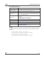
Table 17.
RCCU internal clocks
RCCU Clock
Description
RCCU_CLK2
The reference input clock to the programmable Phase Locked Loop
frequency multiplier.
RCCU_RCLK
Clock Output from RCCU
RCCU_MCLK
Main system clock, to ARM & memory
RCCU_PCLK1
APB1 peripheral clock.
RCCU_PCLK2
APB2 peripheral clock.
RCCU interrupts
The following enumeration defines the RCCU interrupt source. RCCU_Interrupts
enumeration is defined in the file 71x_rccu.h:
typedef enum
{
RCCU_PLL1_LOCK_IT,
RCCU_CKAF_IT,
RCCU_CK2_16_IT,
RCCU_STOP_IT
} RCCU_Interrupts;
Table 18 describes the RCCU interrupts.
Table 18.
RCCU interrupts
RCCU Interrupt
Description
RCCU_PLL1_LOCK_IT
PLL1 lock interrupt
RCCU_CKAF_IT
Clock alternate function switching interrupt
RCCU_CK2_16_IT
Clock2/16 switching interrupt
RCCU_STOP_IT
Stop interrupt
RCCU flags
The following enumeration defines the RCCU flags. RCCU_Flags enumeration is defined in
the file 71x_rccu.h:
typedef enum
{
RCCU_PLL1_LOCK = 0x0002,
RCCU_CKAF_ST = 0x0004,
RCCU_PLL1_LOCK_I = 0x0800,
RCCU_CKAF_I = 0x1000,
RCCU_CK2_16_I = 0x2000,
RCCU_STOP_I = 0x4000
} RCCU_Flags;
34/229
UM0097
Peripheral firmware overview
Table 19 describes the RCCU flags.
Table 19.
RCCU flags
RCCU flag
Description
RCCU_PLL1_LOCK
PLL1 lock interrupt pending flag
RCCU_CKAF_ST
CK_AF Status
RCCU_PLL1_LOCK_I
PLL1 Lock Interrupt pending bit
RCCU_CKAF_I
Clock alternate function switching interrupt pending flag
RCCU_CK2_16_I
Clock2/16 switching interrupt pending flag
RCCU_STOP_I
Stop Interrupt pending bit
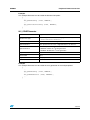
Reset sources
The following enumeration defines the RCCU reset sources. RCCU_ResetSources
enumeration is defined in the file 71x_rccu.h:
typedef enum {
RCCU_ExternalReset = 0x00000000,
RCCU_SoftwareReset = 0x00000020,
RCCU_WDGReset = 0x00000040,
RCCU_RTCAlarmReset = 0x00000080,
RCCU_LVDReset = 0x00000200,
RCCU_WKPReset = 0x00000400
}RCCU_ResetSources;
Table 20 describes the RCCU reset sources.
Table 20.
RCCU reset sources
RCCU reset sources
Description
RCCU_ExternalReset
Reset caused by external pin
RCCU_SoftwareReset
Reset caused by software
RCCU_WDGReset
Reset caused by Watchdog
RCCU_RTCAlarmReset
Reset caused by RTC to wake-up the system from StandBy mode
RCCU_LVDReset
Reset caused by LVD
RCCU_WKPReset
Reset caused by wake-up pin to wake-up the system from StandBy
mode
PLL1 free running modes
The following enumeration defines the PLL1 free dunning modes.
RCCU_PLL1FreeRunningModes enumeration is declared in the file 71x_rccu.h:
typedef enum {
RCCU_PLL1FreeRunning125,
RCCU_PLL1FreeRunning250,
RCCU_PLL1FreeRunning500
}RCCU_PLL1FreeRunningModes;
35/229
Peripheral firmware overview
UM0097
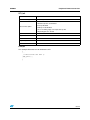
Table 21 describes the PLL1 free running modes.
Table 21.
PLL1 free running modes
PLL1 free running modes
3.2.2
Description
RCCU_PLL1FreeRunning125
PLL1 provides 125 kHz
RCCU_PLL1FreeRunning250
PLL1 provides 250 kHz
RCCU_PLL1FreeRunning500
PLL1 provides 500 kHz
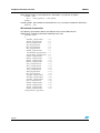
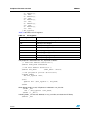
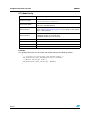
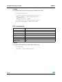
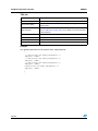
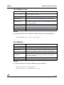
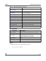
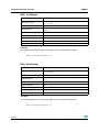
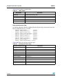
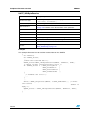
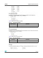
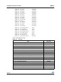
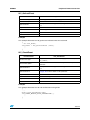
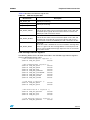
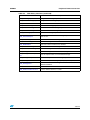
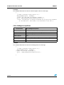
Firmware library functions
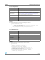
The following table enumerates the different functions of the RCCU library.
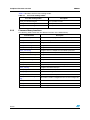
Function Name
Description
RCCU_Div2Config
Enables/Disables the programmable clock division by two
RCCU_Div2Status
Checks if the programmable clock division by 2 is enabled or not
RCCU_MCLKConfig
Configures the MCLK clock divider coefficient
RCCU_PCLK1Config
Configures the PCLK1 clock divider coefficient
RCCU_PCLK2Config
Configures the PCLK2 clock divider coefficient
RCCU_PLL1Config
Configures the PLL1 multiplication and divider parameters
RCCU_PLL2Config
Configures the PLL2 multiplication and divider parameters
RCCU_RCLKSourceConfig
Configures the RCLK clock source
RCCU_RCLKClockSource
Reads and returns the RCLK clock source
RCCU_USBCLKConfig
Configures the USB clock source
RCCU_USBClockSource
Reads and returns the USB clock source
RCCU_FrequencyValue
Computes any internal RCCU clock frequency
RCCU_ITConfig
Configures the RCCU interrupts
RCCU_FlagStatus
Checks the RCCU interrupt status
RCCU_FlagClear
Clears an RCCU flag
RCCU_ResetSource
Returns the source of the system reset
RCCU_PLL1FreeRunningModeC
This routine is used to configures the PLL1 in free running mode
onfig
36/229
RCCU_PLL1Disable
This routine is used to switch off the PLL1
RCCU_PLL2Disable
This routine is used to switch off the PLL2
RCCU_GenerateSWReset
This routine generates software reset.
UM0097
Peripheral firmware overview
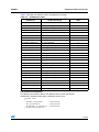
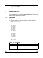
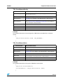
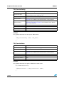
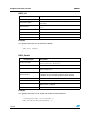
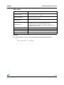
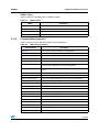
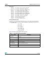
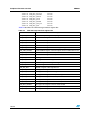
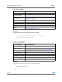
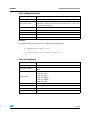
RCCU_Div2Config
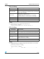
Function Name
RCCU_Div2Config
Function Prototype
void RCCU_Div2Config(FunctionalState NewState);
Behavior Description
This routine is used to enable or disable the programmable clock
division of the CLOCK1 input clock signal by 2. It sets or clears the Div2
flag in the CLK_FLAG register
Input Parameter
NewState: specifies whether the programmable divider can divide the
CLOCK1 input clock signal by two or not
– ENABLE: enables the clock division by two of of CLK signal
– DISABLE: disables the clock division by two of of CLK signal
Output Parameter
None
Return Value
None
Required preconditions
None
Called Functions
None
Example:
This example illustrates how to enable the clock division by two:
RCCU_Div2Config (ENABLE);
/* Sets the Div2 flag in the CLK_FLAG register. */
RCCU_Div2Status
Function Name
RCCU_Div2Status
Function Prototype
FlagStatus RCCU_Div2Status (void);
Behavior Description
This routine gets the current status of the programmable clock division
by two. It checks the status of the Div2 flag in the CLK_FLAG register
Input Parameter
None
Output Parameter
None
Return Value
The Div2 Flag status.
– SET: The division by 2 is enabled
– RESET: The division by 2 is disabled
Required preconditions
None
Called Functions
None
Example:
This example illustrates how to enable the programmable clock divider if it is not enabled.
FlagStatus Current_Div2Flag;
if (Current_Div2Flag == RESET)
{
RCCU_Div2Config (ENABLE);
/*.....................User Code........................*/
}
37/229
Peripheral firmware overview
UM0097
RCCU_MCLKConfig
Function Name
Note:
RCCU_MCLKConfig
Function Prototype
void RCCU_MCLKConfig(Clock_Div New_Clock);
Behavior Description
This routine is used to configure the MCLK clock divider.
Input Parameter
New_Clock: Specifies the MCLK clock divider value.
Refer to Clock divider parameters on page 30 for more details on the
allowed values of this parameter
Output Parameter
None
Return Value
None
Required preconditions
None
Called Functions
None
The MCLK frequency must be greater or equal to the frequency of APB1 and APB2 bridges.
Example:
This example illustrates how to set the MCLK clock to RCLK / 1.
{
...
RCCU_MCLKConfig (RCCU_DEFAULT);
...
}
RCCU_PCLK1Config
Function Name
RCCU_PCLK1Config
Function Prototype
void RCCU_PCLK1Config(Clock_Div New_Clock);
Behavior Description
This routine is used to select the division factor for RCLK to obtain the
PCLK1 clock for the APB1 fast peripherals (PCLK1).
Input Parameter
New_Clock: Specifies the PCLK1 clock divider value.
Refer to Clock divider parameters on page 30 for more details on the
allowed values of this parameter.
Output Parameter
None
Return Value
None
Required preconditions
None
Called Functions
None
Example:
This example illustrates how to set the PCLK1 clock to RCLK / 8.
{
..
RCCU_PCLK1Config(RCCU_RCLK_8);
...
}
38/229
UM0097
Peripheral firmware overview
RCCU_PCLK2Config
Function Name
RCCU_PCLK2Config
Function Prototype
void RCCU_PCLK2Config(Clock_Div New_Clock);
Behavior Description
This routine is used to select the division factor for RCLK to obtain the
PCLK2 clock for the APB2 peripherals (PCLK2).
Input Parameter
New_Clock: specifies the PCLK2 clock divider value. Refer to Clock
divider parameters on page 30 for more details on the allowed values of
this parameter.
Output Parameter
None
Return Value
None
Required preconditions
None
Called Functions
None
Example:
This example illustrates how to set the PCLK2 clock to RCLK / 2.
{
...
RCCU_PCLK2Config (RCCU_RCLK_2);
...
}
RCCU_PLL1Config
Function Name
RCCU_PLL1Config
Function Prototype
void RCCU_PLL1Config (RCCU_PLL1_Mul New_Mul,
RCCU_PLL_Div New_Div );
Behavior Description
This routine configures the PLL1 division and multiplication factors.
Input Parameter 1
New_Mul: the PLL1 clock multiplication factor. Refer to PLL1
multiplication factors on page 31 for more details on the allowed values
of this parameter.
Input Parameter 2
New_Div: the PLL1 clock division factor. Refer to PLL division factors on
page 32 for more details on the allowed values of this parameter.
Output Parameter
None
Return Value
None
Required preconditions
None
Called Functions
None
Example:
This example illustrates how to set the PLL1 multiplication factor to 20 and the divider factor
to 5.
{
...
RCCU_PLL1Config (RCCU_PLL1_Mul_20, RCCU_Div_5);
...
}
39/229
Peripheral firmware overview
UM0097
RCCU_PLL2Config
Function Name
RCCU_PLL2Config
Function Prototype
void RCCU_PLL2Config (RCCU_PLL2_Mul New_Mul,
RCCU_PLL_Div New_Div, u32 HCLK_Clock);
Behavior Description
Configures the PLL2 division and multiplication factors.
Input Parameter 1
New_Mul: the PLL2 clock multiplication factor. Refer to PLL2
multiplication factors on page 32 for more details on the allowed values
of this parameter.
Input Parameter 2
New_Div: the PLL2 clock division factor. Refer to PLL division factors on
page 32 for more details on the allowed values of this parameter.
Input Parameter 3
HCLK_Clock: the clock value present on HCLK pin (in Hz).
Output Parameter
None
Return Value
None
Required preconditions
None
Called Functions
None
Example:
This example illustrates how to set the PLL2 multiplication factor to 28 and the divider factor
to 7.
{
...
RCCU_PLL2Config (RCCU_PLL2_Mul_28, RCCU_Div_7,4000000);
...
}
RCCU_RCLKSourceConfig
Function Name
40/229
RCCU_RCLKSourceConfig
Function Prototype
void RCCU_RCLKSourceConfig(RCLK_Clocks New_Clock);
Behavior Description
This routine selects the clock source for the RCLK.
Input Parameter
New_Clock: the RCLK clock source. Refer to RCLK clock source on
page 31 for more details on the allowed values of this parameter.
Output Parameter
None
Return Value
None
Required preconditions
None
Called Functions
None
UM0097
Peripheral firmware overview
Example:
This example illustrates how to set the PLL1 multiplication factor to 20 and the divider factor
to 4 then select PLL1 output as clock source of RCLK clock.
{
...
RCCU_PLL1Config (RCCU_Mul_20, RCCU_Div_4);
/* Wait PLL to lock */
while(RCCU_FlagStatus (RCCU_PLL1_LOCK) == RESET);
RCCU_RCLKSourceConfig (RCCU_PLL1_Output);
...
}
RCCU_RCLKClockSource
Function Name
RCCU_RCLKClockSource
Function Prototype
RCLK_Clocks RCCU_RCLKClockSource (void);
Behavior Description
This routine gets and returns the current clock source of the RCLK.
Input Parameter
None
Output Parameter
None
Return Value
The current RCLK clock source.
Refer to RCLK clock source on page 31 for more details on the allowed
values of this parameter.
Required preconditions
None
Called Functions
None
Example:
This example illustrates how to get the RCLK clock source.
{
...
RCLK_Clocks RCLK_CLOCK_SOURCE;
RCLK_CLOCK_SOURCE = RCCU_RCLKClockSource ();
...
}
41/229
Peripheral firmware overview
UM0097
RCCU_USBCLKConfig
Function Name
RCCU_USBCLKConfig
Function Prototype
void RCCU_USBCLKConfig (USB_Clocks New_Clock);
Behavior Description
This routine is used to select the clock source of the USB peripheral.
Input Parameter
New_Clock: the USB clock source. Refer to USB clock source on
page 33 for more details on the allowed values of this parameter.
Output Parameter
None
Return Value
None
Required preconditions
None
Called Functions
None
Example:
This example illustrates how to configure the USB peripheral source clock as PLL2 output.
{
...
RCCU_USBCLKConfig (RCCU_PLL2_Output);
...
}
RCCU_USBClockSource
Function Name
RCCU_USBClockSource
Function Prototype
USB_Clocks RCCU_USBClockSource (void);
Behavior Description
This routine gets the clock source of the USB peripheral.
Input Parameter
None
Output Parameter
None
Return Value
The USB clock source. Refer to USB clock source on page 33 for more
details on the allowed values of this parameter.
Required preconditions
None
Called Functions
None
Example:
This example illustrates how to get the USB clock source:
{
RCCU_USB_Clocks Current_USBClock;
...
Current_USBClock = RCCU_USBClockSource ();
...
}
42/229
UM0097
Peripheral firmware overview
RCCU_FrequencyValue
Function Name
RCCU_FrequencyValue
Function Prototype
u32 RCCU_FrequencyValue(RCCU_Clocks Internal_Clk);
Behavior Description
This routine computes any internal RCCU clock frequency value passed
in parameters.
Input Parameter
Internal_Clk: the RCCU internal clock to compute the frequency.
Refer to RCCU internal clocks on page 33 for more details on the
allowed values of this parameter.
Output Parameter
None
Return Value
The frequency value of the specified clock in Hz of the internal clock
passed in parameter.
Required preconditions
None
Called Functions
None
Example:
This example illustrates how get the MCLK clock frequency value.
{
u32 MCLK_Freq;
...
MCLK_Freq = RCCU_FrequencyValue (RCCU_MCLK);
...
}
RCCU_ITConfig
Function Name
RCCU_ITConfig
Function Prototype
void RCCU_ITConfig (RCCU_Interrupts RCCU_IT,
FunctionalState NewState);
Behavior Description
This routine configures the specified RCCU interrupts.
Input Parameter 1
RCCU_IT: specifies the RCCU interrupt to configure. Refer to RCCU
interrupts on page 34 for more details on the allowed values of this
parameter.
Input Parameter 2
NewState: Indicates the new status of the RCCU interrupt.
– ENABLE: to enable the specified interrupt
– DISABLE: to disable the specified interrupt
Output Parameter
None
Return Value
None
Required preconditions
None
Called Functions
None
Example:
This example illustrates how to configure the PLL1 lock interrupt.
{
...
RCCU_ITConfig (RCCU_PLL1_LOCK_IT, ENABLE);
...
}
43/229
Peripheral firmware overview
UM0097
RCCU_FlagStatus
Function Name
RCCU_FlagStatus
Function Prototype
FlagStatus RCCU_FlagStatus(RCCU_Flags RCCU_flag);
Behavior Description
Checks whether the specified interrupt is enabled or disabled.
Input Parameter
RCCU_flag: the flag to see its status. Refer to RCCU flags on page 34
for more details on the allowed values of this parameter.
Output Parameter
None
Return Value
The specified interrupt status.
– SET: The specified flag is set.
– RESET: The specified flag is reset
Required preconditions
None
Called Functions
None
Example:
This example illustrates how to check if the PLL1 is locked.
{
...
while (RCCU_FlagStatus (RCCU_PLL1_LOCK_IT) == RESET);
...
}
RCCU_FlagClear
Function Name
RCCU_FlagClear
Function Prototype
void RCCU_FlagClear (RCCU_Flags RCCU_flag);
Behavior Description
This routine is used to clear the specified interrupt flag in the RCCU
registers passed in parameter.
Input Parameter
RCCU_flag: Specifies the flag to clear. Refer to RCCU flags on page 34
for more details on the allowed values of this parameter.
Output Parameter
None
Return Value
None
Required preconditions
None
Called Functions
None
Example:
This example illustrates how to clear PLL1 lock pending interrupt flag.
{
...
RCCU_FlagClear (RCCU_PLL1_LOCK_I);
...
}
44/229
UM0097
Peripheral firmware overview
RCCU_ResetSource
Function Name
RCCU_ResetSource
Function Prototype
RCCU_ResetSources RCCU_ResetSource (void);
Behavior Description
This routine is used to return the system reset source.
Input Parameter
None
Output Parameter
None
Return Value
The reset source
Required preconditions
None
Called Functions
None
Example:
This example illustrates how to define the system reset source.
{
RCCU_ResetSources ResetSource;
ResetSource=RCCU_ResetSource();
switch (ResetSource)
{
case RCCU_RTCAlarmReset: GPIO_BitWrite(GPIO0,0,1);break;
case RCCU_WKPReset: GPIO_BitWrite(GPIO0,1,1);break;
default
:
GPIO_BitWrite(GPIO0,3,1);break;
}
}
RCCU_PLL1FreeRunningModeConfig
Function Name
RCCU_PLL1FreeRunningModeConfig
Function Prototype
RCCU_PLL1FreeRunningModeConfig(RCCU_PLL1FreeRunningM
odes NewPll1FreeRunningMode);
Behavior Description
This routine is used to configure the PLL1 in free running mode
Input Parameter
RCCU_PLL1FreeRunningModes: PLL1 in free running mode.
Refer to PLL1 free running modes on page 35
Output Parameter
None
Return Value
None
Required preconditions
None
Called Functions
None
Example:
This example shows how to clock the system with the PLL1 configured in free running
mode.
{
/*Configure the PLL in free running mode at 125kHz */
RCCU_PLL1FreeRunningModeConfig(RCCU_PLL1FreeRunning125);
/* Set the RCLK to the PLL1 output */
RCCU_RCLKSourceConfig(RCCU_PLL1_Output);
}
45/229
Peripheral firmware overview
UM0097
RCCU_PLL1Disable
Function Name
RCCU_PLL1Disable
Function Prototype
void RCCU_PLL1Disable (void);
Behavior Description
This routine is used to switch off the PLL1
Input Parameter
None
Output Parameter
None
Return Value
None
Required preconditions
None
Called Functions
None
Example:
This example shows how to switch off the PLL1.
{
/* switch off the PLL1 */
RCCU_PLL1Disable ();
}
RCCU_PLL2Disable
Function Name
RCCU_PLL2Disable
Function Prototype
void RCCU_PLL2Disable (void);
Behavior Description
This routine is used to switch off the PLL2
Input Parameter
None
Output Parameter
None
Return Value
None
Required preconditions
None
Called Functions
None
Example:
This example shows how to switch off the PLL2.
{
/* switch off the PLL2 */
RCCU_PLL2Disable ();
}
46/229
UM0097
Peripheral firmware overview
RCCU_GenerateSWReset
Function Name
RCCU_GenerateSWReset
Function Prototype
void RCCU_GenerateSWReset (void);
Behavior Description
This routine is used to generate a software reset.
Input Parameter
None
Output Parameter
None
Return Value
None
Required preconditions
None
Called Functions
None
Example:
This example shows how to generate the software reset.
{
/* Generate Software Reset */
RCCU_GenerateSWReset ();
}
3.3
Advanced peripheral bus bridges (APB)
The APB driver may be used for a variety of purposes, including APB bridges configuration
and error status reporting.
The first section describes the data structure members used in the APB firmware library.
The second section presents the APB firmware library functions.
3.3.1
Data structures
APB register structure
The APB peripheral register structure APB_TypeDef is defined in the 71x_map.h file as
follows:
typedef struct
{
vu32 CKDIS;
vu32 SWRES;
} APB_TypeDef;
Table 22 presents the APB registers.
Table 22.
APB registers
Register
Description
CKDIS
APB Clock Disable Register
SWRES
APB Software Reset Register
47/229
Peripheral firmware overview
UM0097
The APB bridges are declared in the same file:
...
#define APB1_BASE
0xC0000000
#define APB2_BASE
0xE0000000
....
#ifndef DEBUG
...
#ifdef _APB1
#define APB1
((APB_TypeDef *)(APB1_BASE+0x10))
#endif /*APB1*/
#ifdef _APB2
#define APB2
#endif /*APB2*/
...
#else /* DEBUG */
...
#ifdef _APB1
EXT APB_TypeDef
#endif /*APB1*/
#ifdef _APB2
EXT APB_TypeDef
#endif /*APB2*/
...
#endif
((APB_TypeDef *)(APB2_BASE+0x10))
*APB1;
*APB2;
When debug mode is used, APB pointer is initialized in 71x_lib.c file:
#ifdef _APB1
#ifdef _APB1
APB1 = (APB_TypeDef *)
(APB1_BASE + 0x10);
#endif
#endif /* _APB1 */
#ifdef _APB2
APB2 = (APB_TypeDef *)
#endif /* _APB2 */
(APB2_BASE + 0x10);
In debug mode the following macros are defined in 71x_conf.h file:
48/229
●
_APB is defined to include the APB library
●
_APB1 and _APB2 are defined to access the corresponding peripheral registers.
#define _APB
#define _APB1
#define _APB2
UM0097
Peripheral firmware overview
Bridge peripheral codes
Table 23 enumerates the various peripherals and their defined codes depending on which
bridge they belong.
Table 23.
Bridge peripheral codes
Peripheral
Bridge
Code definition
I2C0_Periph
0x0001
I2C1_Periph
0x0002
UART0_Periph
0x0008
UART1_Periph
0x0010
UART2_Periph
0x0020
UART3_Periph
0x0040
APB1 Bridge
USB_Periph
0x0080
CAN_Periph
0x0100
BSPI0_Periph
0x0200
BSPI1_Periph
0x0400
HDLC_Periph
0x2000
APB1_ALL_Periph
0x27FB
XTI_Periph
0x0001
GPIO0_Periph
0x0004
GPIO1_Periph
0x0008
GPIO2_Periph
0x0010
ADC12_Periph
0x0040
CKOUT_Periph
0x0080
TIM0_Periph
APB2 Bridge
0x0400
TIM1_Periph
0x0200
TIM2_Periph
0x0400
TIM3_Periph
0x0800
RTC_Periph
0x1000
EIC_Periph
0x8000
APB2_ALL_Periph
0x5FDD
Each peripheral code is defined in the 71x_apb.h file. The example below illustrates the
definition of I2C0 peripheral code:
#define I2C0_Periph
0x0001
49/229
Peripheral firmware overview
3.3.2
UM0097
Common parameter values
APBx values
Table 24 shows the allowed values of the APBx variable.
Table 24.
APBx values
APBx
3.3.3
Description
APB1
Selects APB1 bridge
APB2
Selects APB2 bridge
Firmware library functions
Table 25 enumerates the different functions of the APB library.
Table 25.
APB library functions
Function Name
Description
APB_ClockConfig
Enables/Disables the peripheral clock gating on the specified
APB bridge.
APB_SwResetConfig
Enables/Disables the software reset for peripherals on the
specified APB bridge.
APB_ClockConfig
Function Name
Note:
50/229
APB_ClockConfig
Function Prototype
void APB_ClockConfig (APB_TypeDef *APBx,
FunctionalState NewState, u16 Periph);
Behavior Description
Enables/Disables the peripheral clock gating on the specified APB
bridge.
Input Parameter 1
APBx: selects the APB bridge (APB1 or APB2)
Input Parameter 2
NewStatus: specifies if the peripheral clock is running or stopped.
– ENABLE: The peripheral clock is running
– DISABLE: The peripheral clock is stopped.
Input Parameter 3
Periph: specifies the APB bridge peripheral:
Refer to Bridge peripheral codes on page 49 for more details on the
allowed values of this parameter.
Output Parameter
None
Return Value
None
Required preconditions
None
Called Functions
None
1
One or more peripheral clocks can be enabled on the same APB bridge with a single
APB_ClockConfig function call. One or more peripheral clocks can be disabled with another
APB_ClockConfig function call.
2
It is not possible to simultaneously enable and disable several peripheral clocks in a single
APB_ClockConfig function call.
UM0097
Peripheral firmware overview
Example:
This example enables clock gating for I2C0 and UART1 peripherals on the APB1 bridge and
disables the clock for GPIO2, ADC12 peripherals on the APB2 bridge.
{
/* Enables the clock signal to the I2C0 peripheral. */
APB_ClockConfig (APB1, ENABLE, I2C0_Periph);
/* Enables the clock signal to the UART1 peripheral.*/
APB_ClockConfig (APB1, ENABLE, UART1_Periph);
/* Disables the clock signal to the GPIO2 peripheral. */
APB_ClockConfig (APB2, DISABLE, GPIO2_Periph);
/* Disables the clock signal to the ADC12 peripheral. */
APB_ClockConfig (APB2, DISABLE, ADC12_Periph);
}
The APB_ClockConfig parameter 3 can accept several peripherals using the logical
operator OR.
{
/* Enables the clock signal to the I2C0 & UART1 peripherals */
APB_ClockConfig (APB1, ENABLE, I2C0_Periph | UART1_Periph);
/* Disables the clock signal to the GPIO2 & ADC12 peripherals */
APB_ClockConfig (APB2, DISABLE, GPIO2_Periph | ADC12_Periph);
}
51/229
Peripheral firmware overview
UM0097
APB_SwResetConfig
Function Name
Function Prototype
Note:
APB_SwResetConfig
void APB_SwResetConfig (APB_TypeDef *APBx,
FunctionalState New_Status, u16 Periph);
Behavior Description
This function enables/disables the software reset for the specified
peripheral on the specified APB Bridge. It updates the bits[14:0] of the
SWRES register with the value of the input parameter.
Input Parameter 1
APBx: selects the APB bridge (APB1 or APB2).
Input Parameter 2
New_Status: the peripheral software reset new status to be set.
– ENABLE: The peripheral is kept under reset
– DISABLE: The peripheral is reset by the system-wide reset
Input Parameter 3
Periph: specifies the APB bridge peripheral:
Refer to Bridge peripheral codes on page 49 for more details on the
allowed values of this parameter.
Output Parameter
None
Return Value
None
Required preconditions
None
Called Functions
None
1
One or more peripheral software resets can be enabled on the same APB bridge with a
single APB_SwResetConfig function call. One or more peripheral software resets can be
disabled with another APB_SwResetConfig function call.
2
It is not possible to simultaneously enable and disable several peripheral software resets in
a single APB_SwResetConfig function call.
Example:
This example illustrates how to configure the BSPI0 and the BSPI1 peripherals to be kept
always under reset:
{
APB_SwResetConfig (APB1, ENABLE, BSPI0_Periph | BSPI1_Periph);
}
3.4
Enhanced interrupt controller (EIC)
The driver may be used for several purposes, such as enabling and disabling interrupts
(IRQ) and fast interrupts (FIQ), enabling and disabling individual IRQ channels, changing
IRQ channel priorities, saving and restoring context and installing IRQ handlers.
The first and the second sections describe the data structure and the common parameter
values. The second one presents the EIC firmware library functions.
52/229
UM0097
3.4.1
Peripheral firmware overview
Data structures
EIC register structure
The EIC peripheral register structure EIC_TypeDef is defined in the file 71x_map.h as
follows:
typedef volatile struct
{
vu32 ICR;
vu32 CICR;
vu32 CIPR;
u32 EMPTY1[3];
vu32 IVR;
vu32 FIR;
vu32 IER;
u32 EMPTY2[7];
vu32 IPR;
u32 EMPTY3[7];
u32 SIR[32];
} EIC_TypeDef;
Table 26 presents the EIC peripheral registers.
Table 26.
EIC peripheral registers
Register
Description
ICR
Interrupt Control Register
CICR
Current Interrupt Channel Register
CIPR
Current Interrupt Priority Register
IVR
Interrupt Vector Register
FIR
Fast Interrupt Register
IER
Interrupt Enable Register
IPR
Interrupt Pending Register
SIR
Source Interrupt Registers
EIC peripheral is declared in the 71x_map.h file as follows:
...
/* EIC Base Address Definition */
#define EIC_BASE
0xFFFFF800
...
#ifndef DEBUG
...
#ifdef _EIC
#define EIC
((EIC_TypeDef *)EIC_BASE)
#endif /*EIC*/
...
#else /* DEBUG */
...
#ifdef _EIC
EXT EIC_TypeDef
*EIC;
#endif /*EIC*/)
...
#endif
53/229
Peripheral firmware overview
UM0097
When debug mode is used, EIC pointer is initialized in 71x_lib.c file as follows:
#ifdef _EIC
EIC = (EIC_TypeDef *)EIC_BASE;
#endif
In debug mode _EIC variable must be defined in 71x_conf.h file to include the EIC library:
#define _EIC
IRQ channel enumeration
The following enumeration defines the different values of the IRQ channels.
IRQChannel_TypeDef enumeration id defined id eic.h file:
typedef enum
{
T0TIMI_IRQChannel
= 0,
FLASH_IRQChannel
= 1,
RCCU_IRQChannel
= 2,
RTC_IRQChannel
= 3,
WDG_IRQChannel
= 4,
XTI_IRQChannel
= 5,
USBHP_IRQChannel
= 6,
I2C0ITERR_IRQChannel = 7,
I2C1ITERR_IRQChannel = 8,
UART0_IRQChannel
= 9,
UART1_IRQChannel
= 10,
UART2_IRQChannel
= 11,
UART3_IRQChannel
= 12,
SPI0_IRQChannel
= 13,
SPI1_IRQChannel
= 14,
I2C0_IRQChannel
= 15,
I2C1_IRQChannel
= 16,
CAN_IRQChannel
= 17,
ADC_IRQChannel
= 18,
T1TIMI_IRQChannel
= 19,
T2TIMI_IRQChannel
= 20,
T3TIMI_IRQChannel
= 21,
HDLC_IRQChannel
= 25,
USBLP_IRQChannel
= 26,
T0TOI_IRQChannel
= 29,
T0OC1_IRQChannel
= 30,
T0OC2_IRQChannel
= 31
}IRQChannel_TypeDef;
54/229
UM0097
Peripheral firmware overview
Table 27 describes the different values of IRQChannel variable.
Table 27.
IRQChannel values
IRQChannel
Peripheral Interrupt
Value
T0TIMI_IRQChannel
Timer 0 global interrupt
0
FLASH_IRQChannel
Embedded Flash global interrupt
1
RCCU_IRQChannel
RCCU global interrupt
2
RTC_IRQChannel
Real Time Clock global interrupts
3
WDG_IRQChannel
Watchdog timer interrupts
4
XTI_IRQChannel
WIU Wake-up event interrupt
5
USBHP_IRQChannel
USB high priority event interrupt
6
I2C0ITERR_IRQChannel
I2C
0 error interrupt
7
I2C1ITERR_IRQChannel
I2C
1 error interrupt
8
UART0_IRQChannel
UART 0 global interrupt
9
UART1_IRQChannel
UART 1 global interrupt
10
UART2_IRQChannel
UART 2 global interrupt
11
UART3_IRQChannel
UART 3 global interrupt
12
SPI0_IRQChannel
BSPI 0 global interrupt
13
SPI1_IRQChannel
BSPI 1 global interrupt
14
I2C0_IRQChannel
I2C
0 global interrupt
15
I2C1_IRQChannel
I2C
1 global interrupt
16
CAN_IRQChannel
CAN module global interrupt
17
ADC_IRQChannel
ADC sample ready interrupt
18
T1TIMI_IRQChannel
Timer 1 global interrupt
19
T2TIMI_IRQChannel
Timer 2 global interrupt
20
T3TIMI_IRQChannel
Timer 3 global interrupt
21
HDLC_IRQChannel
HDLC global interrupt
25
USBLP_IRQChannel
USB low priority event interrupt
26
T0TOI_IRQChannel
Timer 0 overflow interrupt
29
T0OC1_IRQChannel
Timer 0 output compare 1 interrupt
30
T0OC2_IRQChannel
Timer 0 output compare 2 interrupt
31
FIQ channel enumeration
The following enumeration defines the different values of the FIQ channel.
FIQChannel_TypeDef enumeration is defined in the file eic.h:
typedef enum
{
T0TIMI_FIQChannel
= 0x00000001,
WDG_FIQChannel
= 0x00000002,
WDGT0TIMI_FIQChannels = 0x00000003
} FIQChannel_TypeDef;
55/229
Peripheral firmware overview
UM0097
Table 28 describes the different values of FIQChannel.
Table 28.
FIQChannel values
FIQChannel
3.4.2
Interrupt Source
Value
T0TIMI_FIQChannel
Timer 0 global interrupt
1
WDG_FIQChannel
Watchdog timer interrupt
2
WDGT0TIMI_FIQChannel
Both timer 0 global interrupt and watchdog
interrupt. The two FIQs take place at the
same time.
3
Firmware library functions
The table below enumerates the different functions of the EIC library.
Function Name
56/229
Function Description
EIC_Init
Initializes the Enhanced Interrupt Controller
EIC_IRQConfig
Enables or Disables IRQ interrupts in the EIC
EIC_FIQConfig
Enables or Disables FIQ interrupts in the EIC
EIC_IRQChannelConfig
Enables or Disables the selected IRQ channel interrupts
EIC_FIQChannelConfig
Enables or Disables the selected FIQ channel interrupts
EIC_IRQChannelPriorityConfig
Sets the IRQ channel priority level
EIC_CurrentPriorityLevelValue
Returns the current priority level
EIC_CurrentPriorityLevelConfig
Changes the current priority level
EIC_CurrentIRQChannelValue
Returns the current served IRQ channel number
EIC_CurrentFIQChannelValue
Returns the FIQ channel number causing the FIQ interrupt
EIC_FIQPendingBitClear
Clears FIQ Pending bit according to the input passed
parameter
UM0097
Peripheral firmware overview
EIC_Init
Function Name
Note:
EIC_Init
Function Prototype
void EIC_Init(void);
Behavior Description
Initializes the Interrupt Controller as following:
– FIQ and IRQ are disabled,
– All channel interrupts are disabled,
– All pending bits are cleared.
– The current priority level set to zero,
– IVR register initialized with the upper half of the load PC instruction
op-code,
– All SIR registers are initialized with the offset to the corresponding
IRQ routine vector.
Input Parameter
None
Output Parameter
None
Return Value
None
Required Preconditions
None
Called Functions
None
The EIC is initialized in the 71x_init.s before entering the C code, so you don’t need to
initialize the EIC after a system reset. This function is required if a software reset is
performed.
Example:
This example shows how to initialize the interrupt controller.
{
...
/* Initialize the interrupt controller */
EIC_Init();
...
}
57/229
Peripheral firmware overview
UM0097
EIC_IRQConfig
Function Name
EIC_IRQConfig
Function Prototype
void EIC_IRQConfig(FunctionalState NewState);
Behavior Description
Enables or Disables IRQ interrupts.
Input Parameter
NewState: specifies whether the IRQ is enabled or disabled.
– ENABLE: enables the IRQ interrupt
– DISABLE: disables the IRQ interrupt.
Output Parameter
None
Return Value
None
Required Preconditions
None
Called Functions
None
See also
EIC_FIQConfig on page 58
Example:
This example shows how to enable the IRQ interrupts.
{
...
/*Enable IRQ interrupts */
EIC_IRQConfig(ENABLE);
...
}
EIC_FIQConfig
Function Name
EIC_FIQConfig
Function Prototype
void EIC_FIQConfig(FunctionalState NewState);
Behavior Description
Sets or clears the FIQ_EN bit located in EIC.CIR register.
Input Parameter
NewState: the FIQ interrupt new status to be set.
– ENABLE: enables the FIQ interrupt
– DISABLE: disables the FIQ interrupt.
Output Parameter
None
Return Value
None
Required Preconditions
None
Called Functions
None
See also
EIC_IRQConfig on page 58
Example:
This example shows how to enable the FIQ interrupts.
{
/*Enable FIQ interrupts */
EIC_FIQConfig(ENABLE);
...
}
58/229
UM0097
Peripheral firmware overview
EIC_IRQChannelConfig
Function Name
EIC_IRQChannelConfig
Function Prototype
void EIC_IRQChannelConfig(IRQChannel_TypeDef
IRQChannel, FunctionalState NewState);
Behavior Description
Configures the specified IRQ Channel.
Input Parameter 1
IRQChannel: the channel to be configured.
Refer to IRQ channel enumeration on page 54 for details on allowed
values of IRQChannel parameter.
Input Parameter 2
NewState: specifies whether the IRQ channel interrupt will be enabled
or disabled.
– ENABLE: enables the channel interrupt
– DISABLE: disables the channel interrupt
Output Parameter
None
Return Value
None
Required Preconditions
None
Called Functions
None
See also
EIC_IRQConfig on page 58,
EIC_IRQChannelPriorityConfig on page 61
Example:
This example shows how to enable the Timer 0 global interrupts and disable the UART0
interrupts.
{
...
/* Enable Timer 0 global interrupts */
EIC_IRQChannelConfig(T0TIMI_IRQChannel, ENABLE);
...
/* Disable UART 0 global interrupts */
EIC_IRQChannelConfig(UART0_IRQChannel, DISABLE);
...
}
59/229
Peripheral firmware overview
UM0097
EIC_FIQChannelConfig
Function Name
EIC_FIQChannelConfig
Function Prototype
void EIC_FIQChannelConfig(FIQChannel_TypeDef
FIQChannel, FunctionalState NewState);
Behavior Description
Sets or clears the corresponding channel bit located in EIC.FIR register.
Input Parameter 1
FIQChannel: the FIQ channel to be configured.
Refer to FIQ channel enumeration on page 55 for details on allowed
values of FIQChannel parameter.
Input Parameter 2
NewState: specifies whether the FIQ channel interrupt will be enabled
or disabled.
– ENABLE: enables the FIQ channel interrupt
– DISABLE: disables the FIQ channel interrupt
Output Parameter
None
Return Value
None
Required Preconditions
None
Called Functions
None
See also
EIC_FIQConfig on page 58
Example:
This example how to disable the WDG FIQ interrupts and enable Timer 0 FIQ interrupts.
{
...
/* Disable WDG FIQ interrupts */
EIC_FIQChannelConfig(WDG_FIQChannel, DISABLE);
...
/* Enable Timer 0 FIQ interrupts */
EIC_FIQChannelConfig(T0TIMI_FIQChannel, ENABLE);
...
}
60/229
UM0097
Peripheral firmware overview
EIC_IRQChannelPriorityConfig
Function Name
Caution:
EIC_IRQChannelPriorityConfig
Function Prototype
void EIC_IRQChannelPriorityConfig(
IRQChannel_TypeDef IRQChannel, u8 Priority);
Behavior Description
Configures the selected IRQ channel priority.
Input Parameter 1
IRQChannel: the channel to be configured.
Refer to IRQ channel enumeration on page 54 for details on
allowed values of IRQChannel parameter.
Input Parameter 2
Priority: specifies the priority of the channel. Priority variable must
take an integer value in the range [0..15]
Output Parameter
None
Return Value
None
Required Preconditions
None
Called Functions
None
See also
EIC_IRQConfig on page 58,
EIC_IRQChannelConfig on page 59
If you select a priority level equal to 0, this channel will not be served by the EIC.
Example:
This example show how to enable timer 0 global interrupts with a priority level equal to 5.
{
...
/* Set the timer 0 global interrupts priority level to 5 */
EIC_IRQChannelPriorityConfig(T0TIMI_IRQChannel, 0x05);
...
/* Enable interrupts not the timer 0 global interrupts channel
*/
EIC_IRQChannelConfig(T0TIMI_IRQChannel, ENABLE);
...
/* Enable IRQ interrupts */
EIC_IRQConfig(ENABLE);
...
}
61/229
Peripheral firmware overview
UM0097
EIC_CurrentPriorityLevelValue
Function Name
EIC_CurrentPriorityLevelValue
Function Prototype
u8 EIC_CurrentPriorityLevelValue(void);
Behavior Description
Returns the current priority level of the current served IRQ routine.
Input Parameter
None
Output Parameter
None
Return Value
The current priority level
Required Preconditions
None
Called Functions
None
See also
EIC_CurrentPriorityLevelConfig on page 62
Example:
This example shows how to get the priority level of the current interrupt service routine:
{
vu8 bCurrentPriorityLevelValue;
/* Get the current served IRQ channel priority level.*/
bCurrentPriorityLevelValue = EIC_CurrentPriorityLevelValue();
}
EIC_CurrentPriorityLevelConfig
Function Name
Note:
Function Prototype
void EIC_CurrentPriorityLevelConfig(
u8 NewPriorityLevel);
Behavior Description
This function changes the current priority level of the served IRQ
routine.
Input Parameter
NewPriorityLevel: specifies the new priority level. It must be an integer
in the range [0..15].
Output Parameter
None
Return Value
None
Required Preconditions
None
Called Functions
None
See also
EIC_CurrentPriorityLevelValue on page 62
1
This function changes the current priority level, but doesn’t change the channel priority level.
2
If this function is used in an interrupt service routine, the new priority level must be higher
than the current priority level.
3
To decrease the current priority level you must ensure that all pending bits are cleared.
4
If the EIC_Init() function is used after the EIC_CurrentPriorityLevelConfig() function the
current priority level is reset to zero.
Caution:
62/229
EIC_CurrentPriorityLevelConfig
If this function is used in a non interrupt service routine, all IRQ channels with a priority level
lower or equal to the new priority level will be disabled.
UM0097
Peripheral firmware overview
Examples:
The current priority level is increased by 1.
void an_IRQ_Routine(void)
{
...
EIC_CurrentPriorityLevelConfig(EIC_CurrentPriorityLevelValue()+
1);
...
}
This example shows how to disable all IRQ channel with a priority level lower or equal to 3.
int main(void)
{
...
EIC_CurrentPriorityLevelConfig(3);
...
}
EIC_CurrentIRQChannelValue
Function Name
EIC_CurrentIRQChannelValue
Function Prototype
IRQChannel_TypeDef EIC_CurrentIRQChannelValue(void);
Behavior Description
Returns the current served IRQ channel number.
Input Parameter
None
Output Parameter
None
Return Value
The current served IRQ channel number.
Refer to IRQ channel enumeration on page 54 for details on allowed
values of IRQChannel parameter.
Required Preconditions
None
Called Functions
None
Example:
This example shows how to get the current IRQ channel level value.
{
IRQChannel_TypeDef bCurrentIRQChannelValue;
bCurrentIRQChannelValue = EIC_CurrentIRQChannelValue();
}
63/229
Peripheral firmware overview
UM0097
EIC_CurrentFIQChannelValue
Function Name
Note:
EIC_FIQChannelValue
Function Prototype
FIQChannel_TypeDef EIC_CurrentFIQChannelValue(void);
Behavior Description
This function gets and return the current served FIQ channel number
Input Parameter
None
Output Parameter
None
Return Value
The current served FIQ channel number.
Refer to FIQ channel enumeration on page 55 for details on allowed
values of FIQChannel parameter.
Required Preconditions
None
Called Functions
None
See also
EIC_FIQPendingBitClear on page 65
When you use both Timer 0 and Watchdog Timer FIQ interrupts in your application, this
function is required in the FIQ interrupts service routine for software prioritization and to
define which FIQ pending bit you have to clear.
Example:
This example shows how to use the EIC_FIQChannelValue function in the FIQ interrupts
service routine to define the source of FIQ interrupts.
void FIQ_Handler(void)
{
switch (EIC_CurrentFIQChannelValue())
{
case T0TIMI_FIQChannel:
TIM0->SR &= ~0x2000; // Clear the Timer 0 interrupt flag
/* Clear the corresponding FIQ pending bit */
EIC_FIQPendingBitClear(T0TIMI_FIQChannel);
/*............User code............*/
break;
case WDG_FIQChannel:
WDG->SR = 0x0000; /* Clear the WDG interrupt flag */
/* Clear the corresponding FIQ pending bit */
EIC_FIQPendingBitClear(WDG_FIQChannel);
/*............User code............*/
break;
case WDGT0TIMI_FIQChannels:
WDG->SR = 0x000;
/* Clear the WDG interrupt flag */
TIM0->SR &= ~0x2000; // Clear the Timer 0 interrupt flag
/* Clear the FIQ pending bits */
EIC_FIQPendingBitClear(WDGT0TIMI_FIQChannels);
/*............User code............*/
break;
}
}
64/229
UM0097
Peripheral firmware overview
EIC_FIQPendingBitClear
Function Name
EIC_FIQPendingBitClear
Function Prototype
void EIC_FIQPendingBitClear(FIQChannel_TypeDef
FIQChannel);
Behavior Description
Clears the selected FIQ Pending bit located in FIR register by writing 1
to the corresponding bit.
Input Parameter
FIQChannel: specifies the FIQ channel to be configured.
Refer to FIQ channel enumeration on page 55 for details on allowed
values of FIQChannel parameter.
Output Parameter
None
Return Value
None
Required Preconditions
None
Called Functions
None
See also
EIC_CurrentFIQChannelValue on page 64
Example:
This example shows how to use of the EIC_FIQPendingBitClear function in the FIQ
interrupts service routine to define the source of FIQ interrupts.
void FIQ_Handler(void)
{
TIM0->SR &= ~0x2000; /* Clear the Timer 0 interrupt flag */
/* Clear the corresponding FIQ pending bit */
EIC_FIQPendingBitClear(T0TIMI_FIQChannel);
}
3.5
General purpose input output (GPIO)
The GPIO driver may be used for several purposes, including pin configuration, reading a
port pin and writing data into the port pin.
The first section describes the data structure used in the GPIO firmware library. The second
section presents the GPIO firmware library functions.
3.5.1
Data structures
GPIO register structure
The GPIO peripheral register structure GPIO_TypeDef is defined in the file 71x_map.h as
follows:
typedef struct
{
vu16 PC0;
vu16 EMPTY1;
vu16 PC1;
vu16 EMPTY2;
vu16 PC2;
vu16 EMPTY3;
65/229
Peripheral firmware overview
UM0097
vu16 PD;
vu16 EMPTY4;
} GPIO_TypeDef;
Table 29 describes the GPIO registers.
Table 29.
GPIO registers
Register
Description
PC0
Port Configuration Register 0
PC1
Port Configuration Register 1
PC2
Port Configuration Register 2
PD
Data Register
GPIO peripheral is declared in the 71x_map.h file as follows:
/* APB2 Base Address definition*/
#define APB2_BASE 0xE0000000
/* GPIO0 and GPIO1
#define GPIO0_BASE
#define GPIO1_BASE
#define GPIO2_BASE
Base Address
(APB2_BASE +
(APB2_BASE +
(APB2_BASE +
definitions*/
0x3000)
0x4000)
0x5000)
/* GPIO0 and GPIO1 peripherals declaration*/
#ifndef DEBUG
#ifdef _GPIO0
#define GPIO0
((GPIO_TypeDef *)GPIO0_BASE)
#endif /*GPIO0*/
#ifdef _GPIO1
#define GPIO1
#endif /*GPIO1*/
#ifdef _GPIO2
#define GPIO2
#endif /*GPIO2*/
...
#else /* DEBUG */
#ifdef _GPIO0
EXT GPIO_TypeDef
#endif /*GPIO0*/
#ifdef _GPIO1
EXT GPIO_TypeDef
#endif /*GPIO1*/
#ifdef _GPIO2
EXT GPIO_TypeDef
#endif /*GPIO2*/
...
#endif
66/229
((GPIO_TypeDef *)GPIO1_BASE)
((GPIO_TypeDef *)GPIO2_BASE)
*GPIO0;
*GPIO1;
*GPIO2;
UM0097
Peripheral firmware overview
When debug mode is used, GPIO pointer is initialized in 71x_lib.c file:
#ifdef _GPIO0
GPIO0 = (GPIO_TypeDef *)GPIO0_BASE;
#endif
#ifdef _GPIO1
GPIO1 = (GPIO_TypeDef *)GPIO1_BASE;
#endif
#ifdef _GPIO2
GPIO2 = (GPIO_TypeDef *)GPIO2_BASE;
#endif
In debug mode the following variables are defined in 71x_conf.h file:
●
_GPIO is defined to include the GPIO library
●
_GPIO0, _GPIO1 and _GPIO2 are defined to access the peripheral registers.
#define TQFP144
#define _GPIO
#define _GPIO0
#define _GPIO1
#ifdef TQFP144
#define _GPIO2
#endif /*TQFP144*/
GPIO pin mode enumeration
The following enumeration defines the different possible pin modes for GPIO peripheral.
GpioPinMode_TypeDef enumeration is defined in 71x_gpio.h file:
typedef enum
{
GPIO_HI_AIN_TRI,
GPIO_IN_TRI_TTL,
GPIO_IN_TRI_CMOS,
GPIO_IPUPD_WP,
GPIO_OUT_OD,
GPIO_OUT_PP,
GPIO_AF_OD,
GPIO_AF_PP
} GpioPinMode_TypeDef;
Table 30 describes the pin modes.
Table 30.
GPIO pin modes
Pin mode
Description
GPIO_HI_AIN_TRI
High impedance Analog Input Tristate
GPIO_IN_TRI_TTL
Input Tristate TTL
GPIO_IN_TRI_CMOS
INPUT Tristate CMOS
GPIO_IPUPD_WP
Input Pull-Up/Pull-Down Configuration
GPIO_OUT_OD
Open Drain Output
67/229
Peripheral firmware overview
Table 30.
UM0097
GPIO pin modes (continued)
Pin mode
3.5.2
Description
GPIO_OUT_PP
Push-Pull Output
GPIO_AF_OD
Open Drain Output Alternate-Function
GPIO_AF_PP
Push-Pull Output Alternate-Function
Common parameter values
Port pin values
Table 31 shows the Port_Pins parameter value for each pin.
Table 31.
Port_Pins parameter value
Port_Pin value
Corresponding pin
0x0001
Port pin number 0
0x0002
Port pin number 1
0x0004
Port pin number 2
0x0008
Port pin number 3
0x0010
Port pin number 4
0x0020
Port pin number 5
0x0040
Port pin number 6
0x0080
Port pin number 7
0x0100
Port pin number 8
0x0200
Port pin number 9
0x0400
Port pin number 10
0x0800
Port pin number 11
0x1000
Port pin number 12
0x2000
Port pin number 13
0x4000
Port pin number 14
0x8000
Port pin number 15
GPIOx values
Table 32 shows the allowed values of GPIOx variable.
Table 32.
GPIOx values
GPIOx
68/229
Description
GPIO0
To select GPIO 0
GPIO1
To select GPIO 1
GPIO2
To select GPIO 2
UM0097
3.5.3
Peripheral firmware overview
Firmware library functions
Table 33 enumerates the different functions of the GPIO library.
Table 33.
GPIO library functions
Function Name
Description
GPIO_Config
Configures the selected GPIO I/O pins according to the input
passed in parameter
GPIO_BitRead
Returns a port pin value depending on the input passed parameters
GPIO_ByteRead
Reads the specified data port byte (upper or lower eight bits) and
returns its value
GPIO_WordRead
Reads the specified data port and returns its value
GPIO_BitWrite
Sets or clears the selected data port bit
GPIO_ByteWrite
Writes a byte value into the selected port register byte (upper or lower
eight bits)
GPIO_WordWrite
Writes a word value into the selected port register
GPIO_Config
Function Name
Note:
GPIO_Config
Function Prototype
void GPIO_Config (GPIO_TypeDef *GPIOx,
u16 Port_Pins, GpioPinMode_TypeDef GPIO_Mode);
Behavior Description
Configures the selected GPIO I/O pins according to the input passed
parameters. Refer to the datasheet for more details on input modes,
output modes and port names.
Input Parameter 1
GPIOx: selects the port to be configured. x can be 0, 1 or 2. Refer to
GPIOx values on page 68 for details on the allowed values of this
parameter.
Input Parameter 2
Port_Pins: this parameter specifies the port pin placement. You can
select more than one pin. Refer to Port pin values on page 68 for more
details on the allowed values of this parameter.
Input Parameter 3
GPIO_Mode: specifies the pin mode. Refer to GPIO pin mode
enumeration on page 67 for more information on the allowed values of
this parameter.
Output Parameter
None
Return Value
None
Required preconditions
None
Called Functions
None
1
When you change a port pin mode, the other port pins modes stay unchanged.
2
You can configure more than one pin of the same GPIO peripheral. It is not possible to
configure pins of more than one GPIO peripheral at the same call of GPIO_Config function.
Moreover it is not possible to configure more than one pin of the same GPIO peripheral in
more than one mode by calling once the GPIO_Config function.
69/229
Peripheral firmware overview
UM0097
Example:
This example illustrates how to configure GPIO0, GPIO1 and GPIO2 port pins.
{
#define GPIO_PIN4 0x04
#define GPIO_PIN5 0x05
/*Configure the GPIO0 pin 0 as Open Drain Output */
GPIO_Config (GPIO0, 0x0001, GPIO_OUT_OD);
/*Configure the GPIO0 pins 4 and 5 as a Push-Pull Output */
GPIO_Config (GPIO0, (0x0001<<GPIO_PIN4) | (0x0001<<GPIO_PIN5),
GPIO_OUT_PP);
/*Configure the GPIO0 pin 15 as standard TTL input */
GPIO_Config (GPIO0, 0x8000, GPIO_IN_TRI_TTL);
/*Configure the GPIO1 pins 0, 1, 2 and 3 as High impedance
Analog Input *
GPIO_Config (GPIO1, 0x000F, GPIO_HI_AIN_TRI);
/* Configure all the GPIO2 pins as Push-Pull Output */
GPIO_Config (GPIO2, 0xFFFF, GPIO_OUT_PP);
}
GPIO_BitRead
Function Name
70/229
GPIO_BitRead
Function Prototype
u8 GPIO_BitRead (GPIO_TypeDef *GPIOx, u8 Port_Pin);
Behavior Description
Reads the specified data port bit and returns its value.
Input Parameter 1
GPIOx: selects the port to be read. x can be 0, 1 or 2.
Refer to GPIOx values on page 68 for details on the allowed values of
this parameter.
Input Parameter 2
Port_Pin: Specifies the pin to see the value.
Refer to Port pin values on page 68 for more details on this parameter.
Output Parameter
None
Return Value
The selected port pin value.
It may be 0x00 if the port pin is reset or 0x01 if the port pin is set.
Required preconditions
The port pin must be configured as GPIO_IN_TRI_TTL or as
GPIO_IN_TRI_CMOS mode.
Called Functions
None
See also
GPIO_ByteRead on page 71,
GPIO_WordRead on page 72
UM0097
Peripheral firmware overview
Example:
In This example, the values of GPIO0 port pin 0, GPIO1 port pin 2 and GPIO2 port pin 15
are read.
{
vu8 bValue;
/* Get the P0.0 bit value */
bValue = GPIO_BitRead (GPIO0,0);
/* Get the P1.2 bit value */
bValue = GPIO_BitRead (GPIO1, 2);
/* Get the P2.15 bit value */
bValue = GPIO_BitRead (GPIO2, 15);
}
GPIO_ByteRead
Function Name
GPIO_ByteRead
Function Prototype
u8 GPIO_ByteRead (GPIO_TypeDef *GPIOx,
u8 Port_Byte);
Behavior Description
Reads the specified data port byte and returns its value.
Input Parameter 1
GPIOx: selects the port to be configured. x can be 0, 1 or 2.
Refer to GPIOx values on page 68 for details on the allowed values of
this parameter.
Input Parameter 2
Port_Byte: specifies which byte to be read (upper or lower eight bits) . It
must be one of the following:
– GPIO_MSB corresponds to the upper byte
– GPIO_LSB corresponds to the lower byte.
Output Parameter
None
Return Value
The selected port byte value
Required preconditions
The port pin must be configured as GPIO_IN_TRI_TTL or as
GPIO_IN_TRI_CMOS mode.
Called Functions
None
See also
GPIO_BitRead on page 70,
GPIO_WordRead on page 72
Example:
In This example GPIO0 port lower byte and GPIO1 port upper byte values are read.
{
vu8 bValue;
/* Get P0.[0:7] bits value */
bValue = GPIO_ByteRead (GPIO0, GPIO_LSB);
/* Get P1.[8:15] bits value */
bValue = GPIO_ByteRead (GPIO1, GPIO_MSB);
}
71/229
Peripheral firmware overview
UM0097
GPIO_WordRead
Function Name
GPIO_WordRead
Function Prototype
u16 GPIO_WordRead (GPIO_TypeDef *GPIOx);
Behavior Description
Reads the value of the specified GPIOx PD data port register and
returns its value.
Input Parameter
GPIOx: selects the port to be read. x can be 0, 1 or 2.
Refer to GPIOx values on page 68 for details on the allowed values of
this parameter.
Output Parameter
None
Return Value
The specified port data value
Required preconditions
The port pin must be configured as IN_TRI_TTL or as IN_TRI_CMOS
mode.
Called Functions
None
See also
GPIO_BitRead on page 70,
GPIO_ByteRead on page 71
Example:
This example illustrates how to read the GPIO0 port pin values.
{
u16 wValue;
/* Get all P0 pin value */
wValue = GPIO_WordRead (GPIO0);
}
72/229
UM0097
Peripheral firmware overview
GPIO_BitWrite
Function Name
Note:
GPIO_BitWrite
Function Prototype
void GPIO_BitWrite (GPIO_TypeDef *GPIOx,
u8 Port_Pin, u8 Bit_val);
Behavior Description
Sets or clears the selected data port bit
Input Parameter 1
GPIOx: selects the port. x can be 0, 1 or 2. Refer to GPIOx values on
page 68 for details on the allowed values of this parameter.
Input Parameter 2
Port_Pin: Specifies the pin to set or clear the value.
Refer to Port pin values on page 68 for more details on this parameter.
Input Parameter 3
Bit_Val: the value to be written
0: clear the port pin
1: set the port pin
Output Parameter
None
Return Value
None
Required preconditions
The port pin must be configured as OUT_OD or as OUT_PP.
Called Functions
None
See also
GPIO_ByteWrite on page 74,
GPIO_WordWrite on page 75
1
When a port pin value is changed, the other port pins values stay unchanged.
2
The Input Pull Up/Pull Down Configuration may change according to the related input pin
value.
Example:
This example shows how to clear the GPIO port pin 0 and sets the GPIO1 port pin 15.
{
/* Clear the P0.0 bits */
GPIO_BitWrite(GPIO0, 0, 0);
/* Set the P1.15 bits */
GPIO_BitWrite(GPIO1, 15, 1);
}
73/229
Peripheral firmware overview
UM0097
GPIO_ByteWrite
Function Name
Note:
GPIO_ByteWrite
Function Prototype
void GPIO_ByteWrite (GPIO_TypeDef *GPIOx,
u8 Port_Byte, u8 Port_Val);
Behavior Description
Write byte value to the selected GPIOx PD register.
Input Parameter 1
GPIOx: selects the port. x can be 0, 1 or 2.
Refer to GPIOx values on page 68 for details on the allowed values of
this parameter.
Input Parameter 2
Port_Byte: specifies which byte to be written. It must be one of the
following:
– GPIO_MSB corresponds to the upper byte
– GPIO_LSB corresponds to the lower byte.
Input Parameter 3
Port_Val: the value of the byte to be written.
Output Parameter
None
Return Value
None
Required preconditions
The port pin must be configured as OUT_OD or as OUT_PP.
Called Functions
None
See also
GPIO_BitWrite on page 73,
GPIO_WordWrite on page 75
1
When a port byte value is changed, the other port byte value stay unchanged.
2
The Input Pull Up/Pull Down Configuration may change according to the related input pin
value.
Example:
This example shows how to set all the GPIO0[0:7] port pins and clear all the GPIO1[8:15]
port pins. the GPIO0[8:15] and GPIO1[0:7] remain unchanged.
{
/*Set all the GPIO0[0:7] port pins. */
GPIO_ByteWrite(GPIO0, GPIO_LSB, 0xFF);
/* Clear all the GPI1[8:15] port pins */
GPIO_ByteWrite(GPIO1, GPIO_MSB, 0x00);
}
74/229
UM0097
Peripheral firmware overview
GPIO_WordWrite
Function Name
GPIO_WordWrite
Function Prototype
void GPIO_WordWrite (GPIO_TypeDef *GPIOx,
u16 Port_Val);
Behavior Description
Writes a value in to the selected data port register.
Input Parameter 1
GPIOx: selects the port. x can be 0, 1 or 2.
Refer to GPIOx values on page 68 for details on the allowed values of
this parameter.
Input Parameter 2
Port_Val: holds the word value to be written to the selected data port.
Output Parameter
None
Return Value
None
Required preconditions
The port pin must be configured as GPIO_OUT_OD or as
GPIO_OUT_PP.
Called Functions
None
See also
GPIO_BitWrite on page 73,
GPIO_ByteWrite on page 74
Example:
This example sets all the GPIO0 port pins.
{
/*Set all the GPIO0 port pins */
GPIO_WordWrite(GPIO0, 0xFFFF);
}
3.6
External Interrupts (XTI)
The XTI driver may be used for several purposes, such as firmware IRQ generation,
enabling and disabling interrupt lines, selecting the edge sensitivity, interrupt or Wake-up
mode.
The first section describes the data structure used in the XTI firmware library. The second
section presents the XTI firmware library functions.
3.6.1
Data structures
XTI register structure
The XTI peripheral register structure XTI_TypeDef is defined in the file 71x_map.h as
follows:
typedef volatile struct
{
vu8 SR;
u8 EMPTY1[7];
vu8 CTRL;
u8 EMPTY2[3];
vu8 MRH;
75/229
Peripheral firmware overview
UM0097
u8 EMPTY3[3];
vu8 MRL;
u8 EMPTY4[3];
vu8 TRH;
u8 EMPTY5[3];
vu8 TRL;
u8 EMPTY6[3];
vu8 PRH;
u8 EMPTY7[3];
vu8 PRL;
} XTI_TypeDef;
Table 34 describes the XTI registers.
Table 34.
XTI registers
Register
Description
SR
Wake-Up Software Interrupt Register Low
CTRL
Wake-Up Control Register
MRH
Wake-Up Mask Register High
MRL
Wake-Up Mask Register Low
TRH
Wake-Up Trigger Register High
TRL
Wake-Up Trigger Register Low
PRH
Wake-Up Pending Register High
PRL
Wake-Up Pending Register Low
XTI peripheral is declared in the 71x_map.h file as follows
/* APB2 Base Address definition */
#define APB2_BASE 0xE0000000
/* XTI Base Address definition */
#define XTI_BASE
(APB2_BASE + 0x101C)
/* XTI peripheral pointer declaration*/
#ifndef DEBUG
EXT XTI_TypeDef *XTI;
...
#else
#define XTI ((XTI_TypeDef *) XTI_BASE)
...
#endif
When debug mode is used, XTI pointer is initialized in 71x_lib.c file:
#ifdef _XTI
XTI = (XTI_TypeDef *)XTI_BASE;
#endif /* _XTI */
In debug mode, _XTI must be defined, in 71x_conf.h file, to include the XTI library
#define _XTI
76/229
UM0097
Peripheral firmware overview
Wake-up line mode
The following enumeration defines the input wake-up line modes. XTIMode_TypeDef
enumeration is defined in 71x_xti.h file:
typedef enum
{
XTI_WakeUp = 1,
XTI_Interrupt,
XTI_WakeUpInterrupt
} XTIMode_TypeDef;
Table 35 describes the XTI modes.
:
Table 35.
XTI modes
Pin mode
Description
XTI_WakeUp
The interrupt lines are used to Wake Up the system from the STOP
mode.
XTI_Interrupt
The interrupt lines are used to generate an IRQ interrupt on the XTI
channel.
XTI_WakeUpInterrupt
Interrupt lines are used to generate an IRQ interrupt on the XTI channel
and to wake up the system from the STOP mode.
Trigger edge polarity
The following enumeration defines the values of the trigger edge polarity.
XTITriggerEdge_TypeDef enumeration is defined in 71x_xti.h file:
typedef enum
{
XTI_FallingEdge,
XTI_RisingEdge
} XTITriggerEdge_TypeDef;
Table 36 lists the trigger edge polarity values.
Table 36.
Trigger edge polarity values
Trigger Edge Polarity
3.6.2
Description
XTI_FallingEdge
The Wake-Up interrupt will be set on the falling edge
XTI_RisingEdge
The Wake-Up interrupt will be set on the rising edge
Common parameter values
Lines
Table 37 shows the Lines parameter value for each interrupt line.
Table 37.
Lines values
Lines value
Corresponding Line
XTI_Line0
Line 0: Software interrupt
XTI_Line1
Line 1: USB wake-up event
XTI_Line2
Line 2: External interrupt
77/229
Peripheral firmware overview
Table 37.
UM0097
Lines values (continued)
Lines value
3.6.3
Corresponding Line
XTI_Line3
Line 3: External interrupt
XTI_Line4
Line 4: External interrupt
XTI_Line5
Line 5: External interrupt
XTI_Line6
Line 6: CAN module receive pin
XTI_Line7
Line 7: HDLC clock or I2C0 clock
XTI_Line8
Line 8: HDLC receive pin or I2C0 Data
XTI_Line9
Line 9: BSPI0 slave input data or UART3 receive data input
XTI_Line10
Line 10: BSPI0 slave input serial clock or I2C1 clock
XTI_Line11
Line 11: BSPI1 Slave input serial clock
XTI_Line12
Line 12: UART0 receive data input
XTI_Line13
Line 13: UART1 receive data input
XTI_Line14
Line 14: UART2 receive data input
XTI_Line15
Line 15: WakeUp pin or RTC ALARM
Firmware library functions
Table 38 enumerates the different functions of the XTI library.
Table 38.
XTI library functions
Function Name
78/229
Description
XTI_Init
Initializes the XTI to the default configuration
XTI_ModeConfig
Enables or disables the Interrupt and Wake-Up modes
XTI_LineModeConfig
Selects the line trigger edge polarity
XTI_LineConfig
Enables or disables the selected line interrupt
XTI_InterruptLineValue
Returns the wake-up line number that generates the interrupt
XTI_PendingBitClear
Clears the XTI pending bit
XTI_SWIRQGenerate
Generates a software IRQ interrupt on the XTI channel
UM0097
Peripheral firmware overview
XTI_Init
Function Name
XTI_Init
Function Prototype
void XTI_Init(void);
Behavior Description
This routine is used to initialize the XTI cell:
– All Wake-Up Lines are disabled
– Interrupt disabled
– Walk-up mode disabled
– Set on the falling edge of the input wake-up line
– All pending bits are cleared
Input Parameter
None
Output Parameter
None
Return Value
None
Required preconditions
None
Called Functions
None
Example:
This example illustrates how to initialize the XTI.
{
...
/* Initialize the XTI */
XTI_Init();
...
}
79/229
Peripheral firmware overview
UM0097
XTI_ModeConfig
Function Name
XTI_ModeConfig
Function Prototype
void XTI_ModeConfig(XTIMode_TypeDef Mode,
FunctionalState NewState);
Behavior Description
This function is used to enable or disable the interrupt and the wake-up
mode of the specified input line.
Input Parameter 1
Mode: this parameter specifies the input line.
Refer to Wake-up line mode on page 77 for more details on the allowed
values of this parameter.
Input Parameter 2
NewState: Used to enable or disable the selected mode.
– ENABLE: enables the selected mode
– DISABLE: disables the selected mode.
Output Parameter
None
Return Value
None
Required preconditions
None
Called Functions
None
Example:
This example illustrates how to enable and disable Interrupt and Wake-up modes.
{
/ * Disable the Interrupt and WakeUp modes */
XTI_ModeConfig(XTI_WakeUpInterrupt, DISABLE)
/* Enable Interrupt mode */
XTI_ModeConfig(XTI_Interrupt, ENABLE)
}
80/229
UM0097
Peripheral firmware overview
XTI_LineModeConfig
Function Name
XTI_LineModeConfig
Function Prototype
void XTI_LineModeConfig(u16 Lines,
XTITriggerEdge_TypeDef TriggerEdge);
Behavior Description
This routine is used to configure the trigger edge.
Input Parameter 1
Lines: this parameter specifies the input wake-up line. You can select
more than one line, by logically OR’ing them.
Refer to Section 3.6.2: Common parameter values on page 77 for
details on the allowed values of Lines parameter.
Input Parameter 2
TriggerEdge: specifies the trigger edge polarity of the specified wake-up
lines. Refer to Trigger edge polarity on page 77 for more details on the
allowed values of this parameter.
Output Parameter
None
Return Value
None
Required preconditions
None
Called Functions
None
Example:
This example shows how to set on the rising edge of the input wake-up line 3 and set on the
falling edge of the input wake-up lines 1 and 2.
{
/* Configure the line 3 edge */
XTI_LineModeConfig(XTI_Line3, XTI_RisingEdge);
/* Configure the lines 2 and 1 edge */
XTI_LineModeConfig(XTI_Line2|XTI_Line1, XTI_FallingEdge);
}
81/229
Peripheral firmware overview
UM0097
XTI_LineConfig
Function Name
XTI_LineConfig
Function Prototype
void XTI_LineConfig(u16 Lines,
FunctionalState NewState);
Behavior Description
This routine is used to enable and disable the interrupts lines.
Input Parameter 1
Lines: specifies the lines to be configured. You can select more than one
line, by logically OR’ing them.
Refer to Section 3.6.2: Common parameter values on page 77 for
details on the allowed values of Lines parameter.
Input Parameter 2
NewStatus: the input line interrupt new status to be set.
– ENABLE: to enable the input line interrupt
– DISABLE: to disable the input line interrupt
Output Parameter
None
Return Value
None
Required preconditions
None
Called Functions
None
Example:
This example shows how to enable the line 2 and 1 Wake-Up interrupts and disable the line
3 Wake-Up interrupts.
{
XTI_LineConfig(XTI_Line3, DISABLE);
XTI_LineConfig(XTI_Line2 | XTI_Line1, ENABLE);
}
XTI_InterruptLineValue
Function Name
XTI_InterruptLineValue
Function Prototype
u16 XTI_InterruptLineValue(void);
Behavior Description
Gets and returns the input line number that generates an Interrupt.
Input Parameter
None
Output Parameter
None
Return Value
The line number that generates the interrupt.
Required preconditions
None
Called Functions
None
Example:
This example shows how to get the line number that generates the Wake-Up interrupt.
void XTI_IRQHandler(void)
{
u16 wInterruptLine;
// Read the line number that generates the interrupt.
wInterruptLine = XTI_InterruptLineValue();
}
82/229
UM0097
Peripheral firmware overview
XTI_PendingBitClear
Function Name
XTI_PendingBitClear
Function Prototype
void XTI_PendingBitClear(u16 Lines);
Behavior Description
This routine is used to clear the XTI interrupt pending bits.
Input Parameter
Lines: specifies the input wake-up lines interrupt the input wake-up lines
interrupt. You can select more than one line by logically OR’ing them.
Refer to Section 3.6.2: Common parameter values on page 77 for
details on the allowed values of Lines parameter.
Output Parameter
None
Return Value
None
Required preconditions
None
Called Functions
None
Example:
This example illustrates how to clear the pending bits in the XTI.
void XTI_IRQHandler(void)
{
/* Read the line number that caused the interrupt, then
clear the pending bit. */
XTI_PendingBitClear(XTI_InterruptLineValue());
}
XTI_SWIRQGenerate
Function Name
XTI_SWIRQGenerate
Function Prototype
void XTI_SWIRQGenerate(void);
Behavior Description
This routine is used to generate a software IRQ interrupt.
Input Parameter
None
Output Parameter
None
Return Value
None
Required preconditions
None
Called Functions
None
Example:
This example generates an IRQ interrupt in the XTI channel.
int main(void)
{
/*Enable interrupts in the XTI */
XTI_ModeConfig(Interrupt, ENABLE);
/*Configure the XTI channel priority level */
EIC_IRQChannelPriorityConfig(XTI_IRQChannel, 1);
/* Enable XTI interrupts */
EIC_IRQChannelConfig(XTI_IRQChannel, ENABLE);
/* Enable IRQ interrupts */
83/229
Peripheral firmware overview
UM0097
EIC_IRQConfig(ENABLE);
/* Generate a software IRQ interrupt */
XTI_SWIRQGenerate();
}
3.7
Real time clock (RTC)
The RTC driver may be used for a variety of purposes, including real time clock
management and precise timing operations.
The first section describes the data structures used in the RTC firmware library. The second
section presents the RTC firmware library functions.
3.7.1
Data structures
RTC register structure
The RTC register structure RTC_TypeDef is defined in the 71x_map.h file as follows:
typedef volatile struct
{
vu16 CRH;
u16 EMPTY1;
vu16 CRL;
u16 EMPTY2;
vu16 PRLH;
u16 EMPTY3;
vu16 PRLL;
u16 EMPTY4;
vu16 DIVH;
u16 EMPTY5;
vu16 DIVL;
u16 EMPTY6;
vu16 CNTH;
u16 EMPTY7;
vu16 CNTL;
u16 EMPTY8;
vu16 ALRH;
u16 EMPTY9;
vu16 ALRL;
u16 EMPTY10;
} RTC_TypeDef;
Table 39 describes the RTC structure fields.
Table 39.
RTC structure fields
Register
84/229
Description
CRH
Control High register
CRL
Control Low register
PRLH
Prescaler load value High register
PRLL
Prescaler load value Low register
UM0097
Peripheral firmware overview
Table 39.
RTC structure fields (continued)
Register
Description
DIVH
Prescaler Divider Value High register
DIVL
Prescaler Divider Value Low register
CNTH
Counter High register
CNTL
Counter Low register
ALRH
Alarm High register
ALRL
Alarm Low register
The RTC peripheral is declared in the same file:
...
#define RTC_BASE
0xE000D000
...
#ifndef DEBUG
...
#ifdef _RTC
#define RTC
((RTC_TypeDef *)RTC_BASE)
#endif /*RTC*/
...
#else /* DEBUG */
...
#ifdef _RTC
EXT RTC_TypeDef
*RTC;
#endif /*RTC*/
...
#endif
When debug mode is used, RTC pointer is initialized in the file 71x_lib.c:
#ifdef _RTC
RTC = (RTC_TypeDef *)RTC_BASE;
#endif
In debug mode, _RTC must be defined, in the file 71x_conf.h, to access the peripheral
registers as follows:
#define _RTC
RTC flags
The following enumeration defines the different RTC flags. The RTC_FLAGS enumeration is
defined in the file 71x_rtc.h:
typedef enum
{
RTC_GIR
= 0x0008,
RTC_OWIR = 0x0004,
RTC_AIR
= 0x0002,
RTC_SIR
= 0x0001
} RTC_FLAGS;
85/229
Peripheral firmware overview
UM0097
Table 40 describes the states of RTC flags.
Table 40.
RTC flags
RTC Flags
Description
RTC_GIR
RTC Global Interrupt Request flag
RTC_OWIR
RTC overflow interrupt request
RTC_AIR
RTC Alarm interrupt request
RTC_SIR
RTC Second interrupt request
RTC interrupts
The following enumeration defines the real time clock interrupts. The RTC_IT enumeration
is declared in the file 71x_rtc.h:
typedef enum
{
RTC_GIT = 0x0008,
RTC_OWIT = 0x0004,
RTC_AIT = 0x0002,
RTC_SIT = 0x0001,
} RTC_IT;
Table 41 describes the RTC interrupts.
Table 41.
RTC interrupts
Constant Name
3.7.2
Description
RTC_GIT
The RTC Global Interrupt
RTC_OWIT
The RTC overflow interrupt
RTC_AIT
The RTC Alarm interrupt
RTC_SIT
The RTC Second interrupt
Firmware library functions
Table 42 enumerates the different functions of the RTC library.
Table 42.
RTC library functions
Function Name
86/229
Description
RTC_PrescalerValue
Reads and returns the prescaler value
RTC_PrescalerConfig
Configures the prescaler
RTC_CounterValue
Reads and returns the counter value
RTC_CounterConfig
Update the RTC counter value
RTC_AlarmValue
Reads and returns the Alarm time value
RTC_AlarmConfig
Configures the alarm time value
RTC_FlagStatus
Reads and returns the status of the specified RTC flag
RTC_FlagClear
Clears the specified RTC flag passed in parameter
RTC_ITConfig
Enables / Disables the specified RTC interrupt
UM0097
Peripheral firmware overview
Table 42.
RTC library functions (continued)
Function Name
Description
RTC_ITStatus
Checks the status of the specified RTC interrupt
RTC_ITClear
Clears the specified RTC interrupt
RTC_EnterCfgMode
Enters the RTC configuration mode
RTC_ExitCfgMode
Exit from the configuration mode
RTC_WaitForLastTask
Waits for last task to be finished
RTC_PrescalerValue
Function Name
RTC_PrescalerValue
Function Prototype
u32 RTC_PrescalerValue (void)
Behavior Description
This routine gets the RTC prescaler value.
Input Parameter
None
Output Parameter
None
Return Value
The current RTC prescaler value
Required preconditions
None
Called Functions
None
Example:
This example illustrates how to get the current RTC prescaler value:
{
u32 wCurrent_Prescaler;
...
wCurrent_Prescaler = RTC_PrescalerValue ();
...
}
RTC_PrescalerConfig
Function Name
Note:
RTC_PrescalerConfig
Function Prototype
void RTC_PrescalerConfig (u32 Xprescaler);
Behavior Description
This routine is used to configure the prescaler.
Input Parameter
Xprescaler: specifies the new RTC prescaler value.
Output Parameter
None
Return Value
None
Required preconditions
None
Called Functions
RTC_WaitForLastTask, RTC_EnterCfgMode and RTC_ExitCfgMode
The prescaler is a 20 bit value, the RTC_PrescalerConfig truncates any value, passed in
parameter, that exceeds 20 bits.
87/229
Peripheral firmware overview
UM0097
Example:
This example illustrates how to configure the RTC prescaler value.
{
u32 wNew_Prescaler;
...
/* Reads the previous prescaler value */
wNew_Prescaler = RTC_PrescalerValue ();
/* Add 0xFF */
wNew_Prescaler += 0xFF;
/* Configures the new prescaler value */
RTC_PrescalerConfig (wNew_Prescaler);
...
}
RTC_CounterValue
Function Name
RTC_CounterValue
Function Prototype
u32 RTC_CounterValue (void);
Behavior Description
This routine gets the current RTC counter value.
Input Parameter
None
Output Parameter
None
Return Value
The current RTC counter value
Required preconditions
None
Called Functions
None
Example:
This example illustrates how to get the RTC counter value.
{
u32 wCounter;
...
wCounter = RTC_CounterValue();
...
}
88/229
UM0097
Peripheral firmware overview
RTC_CounterConfig
Function Name
RTC_CounterConfig
Function Prototype
void RTC_CounterConfig (void);
Behavior Description
This routine is used to update the RTC counter with a new value.
Input Parameter
The new RTC counter value
Output Parameter
None
Return Value
None
Required preconditions
None
Called Functions
RTC_EnterCfgMode, RTC_WaitForLastTask and RTC_ExitCfgMode
Example:
This example illustrates how to update the RTC counter with 0x23F value.
{
...
RTC_CounterConfig(0x23F);
...
}
RTC_AlarmValue
Function Name
RTC_AlarmValue
Function Prototype
u32 RTC_AlarmValue (void);
Behavior Description
This routine gets the current RTC alarm value.
Input Parameter
None
Output Parameter
None
Return Value
The current RTC alarm value (u32 format)
Required preconditions
None
Called Functions
None
Example:
This example illustrates how to read the current RTC alarm
value.
{
u32 wCurrent_Alarm_Time;
...
wCurrent_Alarm_Time = RTC_AlarmValue ();
...
}
89/229
Peripheral firmware overview
UM0097
RTC_AlarmConfig
Function Name
RTC_AlarmConfig
Function Prototype
void RTC_AlarmConfig (u32 Xalarm);
Behavior Description
This routine sets the alarm time value. It updates AHI & ALO register
values.
Input Parameter
Xalarm: specifies the new RTC alarm time value.
Output Parameter
None
Return Value
None
Required preconditions
None
Called Functions
RTC_WaitForLastTask, RTC_EnterCfgMode and RTC_ExitCfgMode.
Example:
This example illustrates how to configure a new alarm time.
{
u32 wAlarm_Time;
...
wAlarm_Time = 0x007FFFFF;
...
RTC_AlarmConfig (wAlarm_Time);
...
}
RTC_FlagStatus
Function Name
RTC_FlagStatus
Function Prototype
FlagStatus RTC_FlagStatus (RTC_FLAGS Xflag);
Behavior Description
This routine is used to check if the specified RTC flag is set or not.
Input Parameter
Xflag: Designates an RTC flag. Refer to RTC flags on page 85 for more
details on the allowed values of this parameter.
Output Parameter
None
Return Value
The specified flag status:
– SET: The corresponding flag is SET
– RESET: The corresponding flag is RESET
Required preconditions
None
Called Functions
None
Example:
This example illustrates how to check the RTC Second interrupt flag.
{
...
/* Test if the Second interrupt request is set */
if (RTC_FlagStatus (RTC_SIR))
{
...
}
}
90/229
UM0097
Peripheral firmware overview
RTC_FlagClear
Function Name
RTC_FlagClear
Function Prototype
void RTC_FlagClear (RTC_FLAGS Xflag);
Behavior Description
This routine is used to clear the specified RTC flag.
Input Parameter
Xflag: Designates an RTC flag.
Refer to RTC flags on page 85 for more details on the allowed values of
this parameter.
Output Parameter
None
Return Value
None
Required preconditions
None
Called Functions
RTC_WaitForLastTask, RTC_EnterCfgMode and RTC_ExitCfgMode
Example:
This example illustrates how to clear an RTC pending flag.
{
/* Clear the Alarm request pending flag */
RTC_FlagClear (RTC_AIR);
}
RTC_ITConfig
Function Name
RTC_ITConfig
Function Prototype
void RTC_ITConfig (RTC_IT Xrtcit,
FunctionalState NewState);
Behavior Description
This routine is used to enable or disable the specified RTC interrupt.
Input Parameter 1
Xrtcit: Designates an RTC interrupts. Refer to RTC interrupts on
page 86 for more details on the allowed values of this parameter.
Input Parameter 2
NewState: designates the new interrupt status.
– ENABLE: The corresponding interrupt is enabled
– DISABLE: The corresponding interrupt is disabled
Output Parameter
None
Return Value
None
Required preconditions
None
Called Functions
None
Example:
This example illustrates how to enable the RTC second interrupt.
{
/* Enable the global interrupt */
RTC_ITConfig (RTC_GIT, ENABLE);
/* Enable the Second interrupt */
RTC_ITConfig (RTC_SIT, ENABLE);
}
91/229
Peripheral firmware overview
UM0097
RTC_ITStatus
Function Name
RTC_ITStatus
Function Prototype
FunctionalState RTC_ITStatus (RTC_IT Xrtcit);
Behavior Description
This routine checks whether the specified RTC interrupt is enabled or
not. It reads and returns the CRH flags status.
Input Parameter
Xrtcit: Designates an RTC interrupts. Refer to RTC interrupts on
page 86 for more details on the allowed values of this parameter.
Output Parameter
None
Return Value
The interrupt status:
– ENABLE: the corresponding interrupt is enabled
– DISABLE: the corresponding interrupt is disabled
Required preconditions
None
Called Functions
None
Example:
This example illustrates how to check the alarm interrupt status.
{
/* test if the Alarm interrupt is enabled */
if RTC_ITStatus (RTC_AIT)
{
...
}
}
RTC_ITClear
Function Name
RTC_ITClear
Function Prototype
void RTC_ITClear (RTC_IT Xrtcit);
Behavior Description
This routine is used to clear the specified interrupt pending request.
Input Parameter
Xrtcit: designates an RTC interrupt.
Refer to RTC interrupts on page 86 for more details on the allowed
values of this parameter.
Output Parameter
None
Return Value
None
Required preconditions
None
Called Functions
RTC_WaitForLastTask, RTC_EnterCfgMode and RTC_ExitCfgMode.
Example:
This example illustrates how to clear the second interrupt request.
{
...
RTC_ITClear (RTC_SIT);
...
}
92/229
UM0097
Peripheral firmware overview
RTC_EnterCfgMode
Function Name
RTC_EnterCfgMode
Function Prototype
void RTC_EnterCfgMode(void);
Behavior Description
This routine is used to enter the RTC configuration mode.
Input Parameter
None
Output Parameter
None
Return Value
None
Required preconditions
None
Called Functions
RTC_WaitForLastTask
Example:
This example illustrates how to enter in configuration mode.
{
...
RTC_EnterCfgMode ();
...
}
RTC_ExitCfgMode
Function Name
RTC_ExitCfgMode
Function Prototype
void RTC_ExitCfgMode(void);
Behavior Description
This routine is used to exit from the RTC configuration mode.
Input Parameter
None
Output Parameter
None
Return Value
None
Required preconditions
None
Called Functions
RTC_WaitForLastTask
Example:
This example illustrates how to exit from configuration mode.
{
...
RTC_ExitCfgMode ();
...
}
93/229
Peripheral firmware overview
UM0097
RTC_WaitForLastTask
Function Name
RTC_WaitForLastTask
Function Prototype
void RTC_WaitForLastTask(void);
Behavior Description
This routine waits for the task to be completed on the RTC registers.
Input Parameter
None
Output Parameter
None
Return Value
None
Required preconditions
None
Called Functions
None
Example:
This example illustrates how to use the RTC_WaitForLastTask function.
{
...
RTC_WaitForLastTask();
...
}
3.8
Watchdog timer (WDG)
The WDG driver may be used for a variety of purposes, including timing operations and
watchdog functions.
The first section describes the data structures used in the WDG firmware library. The
second section presents the WDG firmware library functions.
3.8.1
Data structures
WDG register structure
The WDG register structure WDG_TypeDef is defined in the 71x_map.h file as follows:
typedef volatile struct
{
vu16 CR;
u16 EMPTY1;
vu16 PR;
u16 EMPTY2;
vu16 VR;
u16 EMPTY3;
vu16 CNT;
u16 EMPTY4;
vu16 SR;
u16 EMPTY5;
vu16 MR;
u16 EMPTY6;
vu16 KR;
u16 EMPTY7
} WDG_TypeDef;
94/229
UM0097
Peripheral firmware overview
Table 43 describes the WDG structure fields.
Table 43.
WDG structure fields
Register
Description
CR
Control register
PR
Prescaler register
VR
Pre-load Value register
CNT
Counter register
SR
Status Register
MR
Mask Register
KR
Key Register
The WDG peripherals are declared in the same file:
...
#define WDG_BASE
(APB2_BASE + 0xE000)
...
#ifndef DEBUG
...
#ifdef _WDG
#define WDG
((WDG_TypeDef *)WDG_BASE)
#endif /*WDG*/
...
#else /* DEBUG */
...
#ifdef _WDG
EXT WDG_TypeDef
*WDG;
#endif /*WDG*/
...
#endif
When debug mode is used, WDG pointers are initialized in the file 71x_lib.c:
#ifdef _WDG
WDG = (WDG_TypeDef *)WDG_BASE;
#endif
In debug mode, _WDG must be defined, in the file 71x_conf.h, to access the peripheral
registers as follows:
#define _WDG
Some RCCU functions are called, _RCCU must be defined, in 71x_conf.h file, to make the
RCCU functions accessible:
#define _RCCU
95/229
Peripheral firmware overview
3.8.2
UM0097
Firmware library functions
Table 44 enumerates the different functions of the WDG library.
Table 44.
WDG library functions
Function Name
Description
WDG_Enable
Enable Watchdog Mode
WDG_CntRefresh
Refresh and update the WDG counter to avoid a system reset
WDG_PrescalerConfig
Set the counter prescaler value. Divide the counter clock by (Prescaler
+ 1)
WDG_CntReloadUpdate
Update the counter pre-load value
WDG_PeriodValueConfig
Set the prescaler and counter reload value based on the time needed
WDG_CntOnOffConfig
Start or stop the free auto-reload timer to countdown
WDG_ECITConfig
Enable or Disable the end of count interrupt
WDG_ECFlagClear
Clear the end of count flag
WDG_ECStatus
Return the end of count status.
WDG_Enable
Function Name
WDG_Enable
Function Prototype
void WDG_Enable ( void );
Behavior Description
This routine is used to enable Watchdog mode.
Input Parameter
None
Output Parameter
None
Return Value
None
Required preconditions
None
Called Functions
None
Example:
This example illustrates how to enable Watchdog mode:
{
...
/* Enable the watchdog mode */
WDG_Enable ();
...
}
96/229
UM0097
Peripheral firmware overview
WDG_CntRefresh
Function Name
WDG_CntRefresh
Function Prototype
void WDG_CntRefresh (void);
Behavior Description
This routine is used to refresh the counter to prevent a reset being
generated by the Watchdog. It writes 0xA55A then 0x5AA5 in the key
register.
Input Parameter
None
Output Parameter
None
Return Value
None
Required preconditions
None
Called Functions
None
Example:
This example illustrates how to refresh the watchdog counter.
{
...
WDG_CntRefresh ();
...
}
WDG_PrescalerConfig
Function Name
WDG_PrescalerConfig
Function Prototype
void WDG_PrescalerConfig (u8 Prescaler);
Behavior Description
This routine is used to set the the counter prescaler value. The clock to
Timer Counter is divided by (Prescaler + 1)
Input Parameter
Prescaler: specifies the prescaler value (8 bit).
Output Parameter
None
Return Value
None
Required preconditions
None
Called Functions
None
Example:
This example illustrates how to set the prescaler value.
{
...
WDG_PrescalerConfig (0x62);
...
}
97/229
Peripheral firmware overview
UM0097
WDG_CntReloadUpdate
Function Name
WDG_CntReloadUpdate
Function Prototype
void WDG_CntReloadUpdate (u16 PreLoadValue);
Behavior Description
This routine is used to update the counter pre-load value.
Input Parameter
PreLoadValue specifies the pre-load value (16 bit).
Output Parameter
None
Return Value
None
Required preconditions
None
Called Functions
None
Example:
This example illustrates how to configure the WDG pre-load value.
{
...
void WDG_CntReloadUpdate (0x1234);
...
}
WDG_PeriodValueConfig
Function Name
WDG_PeriodValueConfig
Function Prototype
void WDG_PeriodValueConfig (u32 Time);
Behavior Description
This routine is used to set the prescaler and counter reload value.
Input Parameter
Time: the amount of time needed, in microseconds.
Output Parameter
None
Return Value
None
Required preconditions
None
Called Functions
RCCU_FrequencyValue, FindFactors
Example:
This example illustrates how to set the needed time (µs).
{
...
WDG_PeriodValueConfig (2589);
...
}
98/229
UM0097
Peripheral firmware overview
WDG_CntOnOffConfig
Function Name
WDG_CntOnOffConfig
Function Prototype
void WDG_CntOnOffConfig (FunctionalState NewState);
Behavior Description
This routine is used to start or stop the free auto-reload timer counting
down.
Input Parameter
NewState: specifies how the timer has to be started or stopped.
Output Parameter
None
Return Value
None
Required preconditions
None
Called Functions
None
Example:
This example illustrates how to configure the WDG in order to start or stop the timer.
{
...
/* stop the counter */
WDG_CntOnOffConfig (DISABLE);
/* Start the counter */
WDG_CntOnOffConfig (ENABLE);
...
}
WDG_ECITConfig
Function Name
WDG_ECITConfig
Function Prototype
void WDG_ECITConfig (FunctionalState NewState)
Behavior Description
Enable or Disable the WDG end of count interrupt.
Input Parameter
NewState: specifies whether the WDG end of count interrupt is enabled
or disabled.
– ENABLE: enables the WDG IRQ interrupt
– DISABLE: disables the WDG IRQ interrupt.
Output Parameter
None
Return Value
None
Required preconditions
None
Called Functions
None
Example:
This example illustrates how to enable the WDG end of count interrupt.
{
...
WDG_ECITConfig(ENABLE);
...
}
99/229
Peripheral firmware overview
UM0097
WDG_ECFlagClear
Function Name
WDG_ECFlagClear
Function Prototype
void WDG_ECFlagClear (void);
Behavior Description
This routine is used to clear the end of count flag.
Input Parameter
None
Output Parameter
None
Return Value
None
Required preconditions
None
Called Functions
None
Example:
This example illustrates how clear the end of count pending bit.
{
...
WDG_ECFlagClear ();
...
}
WDG_ECStatus
Function Name
WDG_ECStatus
Function Prototype
u16 WDG_ECStatus (void);
Behavior Description
Read the status register.
Input Parameter
None
Output Parameter
None
Return Value
The end of count status
Required preconditions
None
Called Functions
None
Example:
This example illustrates how to get the end of count status
{
...
u16 hStatus;
hStatus = WDG_ECStatus();
...
}
100/229
UM0097
3.9
Peripheral firmware overview
Timer (TIM)
The TIM driver may be used for a variety of purposes, including timing operations, external
wave generation and measurement.
The first section describes the data structures used in the TIM firmware library. The second
section presents the TIM firmware library functions.
3.9.1
Data structures
TIM register structure
The TIM register structure TIM_TypeDef is defined in the 71x_map.h file as follows:
typedef volatile struct
{
vu16 ICAR;
u16 EMPTY1;
vu16 ICBR;
u16 EMPTY2;
vu16 OCAR;
u16 EMPTY3;
vu16 OCBR;
u16 EMPTY4;
vu16 CNTR;
u16 EMPTY5;
vu16 CR1;
u16 EMPTY6;
vu16 CR2;
u16 EMPTY7;
vu16 SR;
u16 EMPTY8;
} TIM_TypeDef;
Table 45 describes the TIM structure fields.
Table 45.
TIM structure fields
Register
Description
ICAR
Input capture A register
ICBR
Input capture B register
OCAR
Output Compare A register
OCBR
Output Compare B register
CNTR
Counter Register
CR1
Control Register 1
CR2
Control Register 2
SR
Status Register
The TIM peripherals are declared in the same file:
...
#define TIM0_BASE
(APB2_BASE + 0x9000)
#define TIM1_BASE
(APB2_BASE + 0xA000)
101/229
Peripheral firmware overview
#define TIM2_BASE
#define TIM3_BASE
...
#ifndef DEBUG
...
#ifdef _TIM0
#define TIM0
#endif /*TIM0*/
UM0097
(APB2_BASE + 0xB000)
(APB2_BASE + 0xC000)
((TIM_TypeDef *)TIM0_BASE)
#ifdef _TIM1
#define TIM1
#endif /*TIM1*/
((TIM_TypeDef *)TIM1_BASE)
#ifdef _TIM2
#define TIM2
#endif /*TIM2*/
((TIM_TypeDef *)TIM2_BASE)
#ifdef _TIM3
#define TIM3
#endif /*TIM3*/
...
#else /* DEBUG */
...
#ifdef _TIM0
EXT TIM_TypeDef
#endif /*TIM0*/
((TIM_TypeDef *)TIM3_BASE)
*TIM0;
#ifdef _TIM1
EXT TIM_TypeDef
#endif /*TIM1*/
*TIM1;
#ifdef _TIM2
EXT TIM_TypeDef
#endif /*TIM2*/
*TIM2;
#ifdef _TIM3
EXT TIM_TypeDef
#endif /*TIM3*/
...
#endif
*TIM3;
When debug mode is used, TIM pointers are initialized in the file 71x_lib.c:
#ifdef _TIM0
TIM0 = (TIM_TypeDef *)TIM0_BASE;
#endif
#ifdef _TIM1
TIM1 = (TIM_TypeDef *)TIM1_BASE;
#endif
#ifdef _TIM2
TIM2 = (TIM_TypeDef *)TIM2_BASE;
#endif
102/229
UM0097
Peripheral firmware overview
#ifdef _TIM3
TIM3 = (TIM_TypeDef *)TIM3_BASE;
#endif
TIM0 = (TIM_TypeDef *)TIM0_BASE;
In debug mode, _TIMx must be defined in the file 71x_conf.h to access the peripheral
registers as follows:
#define _TIMx (x=0..3)
TIM values
Table 46 enumerates the different values of the TIMx.
Table 46.
TIMx values
TIM Value
Description
TIM0
Timer 0
TIM1
Timer 1
TIM2
Timer 2
TIM3
Timer 3
TIM flags enumeration
The following enumeration defines the different TIM flags. The TIM_Flags enumeration is
defined in the file 71x_tim.h:
typedef enum
{
TIM_ICFA = 0x8000,
TIM_OCFA = 0x4000,
TIM_TOF = 0x2000,
TIM_ICFB = 0x1000,
TIM_OCFB = 0x0800
} TIM_Flags;
Table 47 describes the states of TIM flags.
Table 47.
TIM flags
TIM Flags
Description
TIM_ICFA
TIM Input Capture channel A flag
TIM_OCFA
TIM Output Compare channel A flag
TIM_TOF
TIM Timer Overflow flag
TIM_ICFB
TIM Input Capture channel B flag
TIM_OCFB
TIM Output Compare channel B flag
103/229
Peripheral firmware overview
UM0097
Clock sources enumeration
The following enumeration defines the different TIM clock sources. The TIM_Clocks
enumeration is defined in the file 71x_tim.h:
typedef enum
{
TIM_EXTERNAL,
TIM_INTERNAL
} TIM_Clocks;
Table 48 enumerates the clock sources.
Table 48.
TIM clock sources
Clock Source
Description
TIM_EXTERNAL
The TIM peripheral is clocked by the external clock
TIM_INTERNAL
The TIM peripheral is clocked by APB clock
Clock edges enumeration
The following enumeration defines the different TIM clock edges. The TIM_Clock_Edges
enumeration is defined in the file 71x_tim.h:
typedef enum
{
TIM_RISING,
TIM_FALLING
} TIM_Clock_Edges;
Table 49 enumerates the clock edges.
Table 49.
TIM clock edges
clock Edge
Description
TIM_RISING
The active edge is the rising edge
TIM_FALLING
The active edge is the falling edge
TIM channels enumeration
The following enumeration defines the different TIM channels. The TIM_Channels
enumeration is defined in the file 71x_tim.h:
typedef enum
{
TIM_CHANNEL_A,
TIM_CHANNEL_B
} TIM_Channels;
Table 50 enumerates the TIM channels.
Table 50.
TIM channels
TIM Channel
104/229
Description
TIM_CHANNEL_A
Channel A
TIM_CHANNEL_B
Channel B
UM0097
Peripheral firmware overview
Output compare modes enumeration
The following enumeration defines the Output Compare modes. The OC_Modes
enumeration is defined in the file 71x_tim.h:
typedef enum
{
TIM_TIMING,
TIM_WAVE
} TIM_OC_Modes;
Table 51 enumerates the output compare modes.
Table 51.
Output compare modes
Output Compare Mode
Description
TIM_TIMING
The output compare mode is used for internal operations
TIM_WAVE
The output compare mode is only used for external wave generation
operations
Logic levels enumeration
The following enumeration defines the different logic levels. The Logic_Levels enumeration
is defined in the file 71x_tim.h:
typedef enum
{
TIM_HIGH,
TIM_LOW
} TIM_Logic_Levels;
Table 52 enumerates the logic levels.
Table 52.
Logic levels
Logic level
Description
TIM_HIGH
The output compare is forced to the high level after the match between
the counter and the output compare register.
TIM_LOW
The output compare is forced to the low level after the match between
the counter and the output compare register.
Counter operations enumeration
The following enumeration defines the different counter operations. The CounterOperations
enumeration is defined in the file 71x_tim.h:
typedef enum
{
TIM_START,
TIM_STOP,
TIM_CLEAR
} TIM_CounterOperations;
105/229
Peripheral firmware overview
UM0097
Table 53 enumerates the counter operations.
Table 53.
Counter operations
Counter Operation
Description
TIM_START
Enables or resumes the counter
TIM_STOP
Stops the TIM counter
TIM_CLEAR
Clears the TIM counter value and set its value to FFFCh
PWM input parameters structure
The following structure defines the different PWM input parameters. The PWMI_parameters
structure is defined in the file 71x_tim.h:
typedef struct
{
u16 Pulse,
u16 Period
} PWMI_parameters;
Table 54 defines the PWM input parameters.
Table 54.
PWM input parameters
Structure Field
Description
Pulse
The pulse of the external signal
Period
The period of the external signal
TIM interrupts
The following section lists the different TIM interrupts. Those interrupts are declared in the
file 71x_tim.h:
#define TIM_ICA_IT
0x8000
#define TIM_OCA_IT
0x4000
#define TIM_TO_IT
0x2000
#define TIM_ICB_IT
0x1000
#define TIM_OCB_IT
0x0800
Table 55 describes the TIM interrupts.
Table 55.
TIM interrupts
TIM Interrupts
106/229
Description
TIM_ICA_IT
TIM Input Capture Channel A interrupt
TIM_OCA_IT
TIM Output Compare channel A interrupt
TIM_TO_IT
TIM Timer Overflow interrupt
TIM_ICB_IT
TIM Input Capture Channel A interrupt
TIM_OCB_IT
TIM Output Compare channel B interrupt
UM0097
3.9.2
Peripheral firmware overview
Firmware library functions
Table 56 enumerates the different functions of the TIM library.
Table 56.
TIM library functions
Function Name
Description
TIM_Init
Initializes the TIM peripheral
TIM_ClockSourceConfig
Configures the TIM clock source
TIM_ClockSourceValue
Gets the TIM clock source
TIM_PrescalerConfig
Configures the TIM prescaler Value
TIM_PrescalerValue
Gets the TIM prescaler Value
TIM_ClockLevelConfig
Configures the active clock level when the TIM is clocked by an
external source
TIM_ClockLevelValue
Gets the active clock level when the TIM is clocked by an external
source
TIM_ICAPModeConfig
Configures the Input capture mode
TIM_ICAPValue
Gets the Input capture values
TIM_OCMPModeConfig
Configures the Output compare mode
TIM_OPModeConfig
Configures the One pulse mode
TIM_PWMOModeConfig
Configures the PWM output mode
TIM_PWMIModeConfig
Configures the PWM input mode
TIM_PWMIValue
Reads and returns the PWM input parameters
TIM_ITConfig
Configures the TIM interrupts
TIM_FlagStatus
Gets the TIM flag Status
TIM_FlagClear
Clears the TIM pending flag
TIM_CounterConfig
Configures the TIM counter
TIM_CounterValue
This routine returns the timer counter value.
107/229
Peripheral firmware overview
UM0097
TIM_Init
Function Name
TIM_Init
Function Prototype
void TIM_Init (TIM_TypeDef *TIMx);
Behavior Description
This routine is used to Initialize the TIM peripheral registers to their
default values.
Input Parameter
TIMx specifies the TIM to be initialized.
Refer to TIM values on page 103 for more details on the allowed values
of this parameter.
Output Parameter
None
Return Value
None
Required preconditions
None
Called Functions
None
Example:
This example illustrates how to initialize all the TIM peripherals:
{
...
/* Initialize the TIM0 peripheral */
TIM_Init (TIM0);
/* Initialize the TIM1 peripheral */
TIM_Init (TIM1);
/* Initialize the TIM2 peripheral */
TIM_Init (TIM2);
/*Initialize the TIM3 peripheral */
TIM_Init (TIM3);
...
}
108/229
UM0097
Peripheral firmware overview
TIM_ClockSourceConfig
Function Name
TIM_ClockSourceConfig
Function Prototype
void TIM_ClockSourceConfig (TIM_TypeDef *TIMx,
TIM_Clocks Xclock);
Behavior Description
This routine configures the source clock of the TIM peripheral.
Input Parameter 1
TIMx: specifies the TIM to be configured. Refer to TIM values on
page 103 for more details on the allowed values of this parameter.
Input Parameter 2
Xclock specifies the TIM source clock.
Refer to Clock sources enumeration on page 104 for more details on
the allowed values of this parameter.
Output Parameter
None
Return Value
None
Required preconditions
None
Called Functions
None
Example:
This example illustrates how to configure the TIM0 timer to be clocked by an external
source.
{
...
TIM_ClockSourceConfig (TIM0, TIM_EXTERNAL);
...
}
TIM_ClockSourceValue
Function Name
TIM_ClockSourceValue
Function Prototype
TIM_Clocks TIM_ClockSourceValue TIM_TypeDef *TIMx);
Behavior Description
This routine gets the source clock of the TIM peripheral.
Input Parameter
TIMx: specifies the TIM to check its source clock. Refer to TIM values
on page 103 for more details on the allowed values of this parameter.
Output Parameter
None
Return Value
The TIM source clock. Refer to Clock sources enumeration on page 104
for more details on the allowed values of this parameter.
Required preconditions
None
Called Functions
None
Example:
This example illustrates how to get the TIM0 timer source clock.
{
TIM_Clocks CurrentTIMClock;
...
CurrentTIMClock = TIM_ClockSourceValue (TIM0);
...
}
109/229
Peripheral firmware overview
UM0097
TIM_PrescalerConfig
Function Name
TIM_PrescalerConfig
Function Prototype
void TIM_PrescalerConfig (TIM_TypeDef *TIMx, u8
Xprescaler);
Behavior Description
This routine configures the TIM prescaler value to divide the internal
clock.
Input Parameter 1
TIMx specifies the TIM to be configured. Refer to TIM values on
page 103 for more details on the allowed values of this parameter.
Input Parameter 2
Xprescaler: specifies the TIM prescaler value (8bit).
Output Parameter
None
Return Value
None
Required preconditions
None
Called Functions
None
Example:
This example illustrates how to configure the TIM3 prescaler.
{
...
TIM_PrescalerConfig (TIM3, 0x5);
...
}
TIM_PrescalerValue
Function Name
TIM_PrescalerValue
Function Prototype
u8 TIM_PrescalerValue (TIM_TypeDef *TIMx);
Behavior Description
This routine gets the TIM prescaler value when the internal clock is
used.
Input Parameter
TIMx: specifies the timer to get its prescaler value. Refer to TIM values
on page 103 for more details on the allowed values of this parameter.
Output Parameter
None
Return Value
The Current TIM prescaler Value (8bit).
Required preconditions
None
Called Functions
None
Example:
This example illustrates how to get the TIM2 prescaler value.
{
vu8 bCurrentPrescaler;
...
bCurrentPrescaler = TIM_PrescalerConfig (TIM2);
...
}
110/229
UM0097
Peripheral firmware overview
TIM_ClockLevelConfig
Function Name
TIM_ClockLevelConfig
Function Prototype
void TIM_ClockLevelConfig (TIM_TypeDef *TIMx,
Clock_Levels Xlevel);
Behavior Description
This routine configures the active level when using an external clock
source.
Input Parameter 1
TIMx: specifies the TIM to be configured. Refer to TIM values on
page 103 for more details on the allowed values of this parameter.
Input Parameter 2
Xlevel: specifies the active edge of the external clock. Refer to Clock
edges enumeration on page 104 for more details on the allowed values
of this parameter.
Output Parameter
None
Return Value
None
Required preconditions
None
Called Functions
None
Example:
This example illustrates how to configure the TIM0 to be clocked by an external clock source
and the active edge to falling edge.
{
...
/* Configure the Active Clock edge */
TIM_ClockLevelConfig (TIM0, TIM_FALLING);
/* Configure the TIM0 source clock */
TIM_ClockSourceConfig (TIM0, TIM_EXTERNAL)
...
}
111/229
Peripheral firmware overview
UM0097
TIM_ClockLevelValue
Function Name
TIM_ClockLevelValue
Function Prototype
Clock_Levels TIM_ClockLevelValue (TIM_TypeDef *TIMx);
Behavior Description
This routine gets and returns the clock active level when using an
external clock source.
Input Parameter
TIMx: specifies the TIM to be configured. Refer to TIM values on
page 103 for more details on the allowed values of this parameter.
Output Parameter
None
Return Value
The external clock level of the specified timer. Refer to Clock edges
enumeration on page 104 for more details on the allowed values of this
parameter.
Required preconditions
None
Called Functions
None
Example:
This example illustrates how to get the current clock level of the TIM0.
{
...
TIM_Clock_Edges CurrentLevel;
CurrentLevel = TIM_ClockLevelValue (TIM0);
...
}
TIM_ICAPModeConfig
Function Name
112/229
TIM_ICAPModeConfig
Function Prototype
void TIM_ICAPModeConfig (TIM_TypeDef *TIMx,
TIM_Channels Xchannel, Clock_Edges Xedge);
Behavior Description
This routine is used to configure the Input capture mode.
Input Parameter 1
TIMx specifies the TIM to be initialized. Refer to TIM values on
page 103 for more details on the allowed values of this parameter.
Input Parameter 2
Xchannel: specifies the input capture channels. Refer to TIM channels
enumeration on page 104 for more details on the allowed values of this
parameter.
Input Parameter 3
Xedge: specifies the input capture sensitive edge. Refer to Clock edges
enumeration on page 104 for more details on the allowed values of this
parameter.
Output Parameter
None
Return Value
None
Required preconditions
None
Called Functions
None
UM0097
Peripheral firmware overview
Example:
This example illustrates how to configure the TIM3 input capture channel A to detect Rising
edge.
{
...
TIM_ICAPModeConfig (TIM3, TIM_CHANNEL_A, TIM_RISING);
...
}
TIM_ICAPValue
Function Name
TIM_ICAPValue
Function Prototype
u16 TIM_ICAPValue (TIM_TypeDef *TIMx,
TIM_Channels Xchannel);
Behavior Description
This routine gets the input capture value.
Input Parameter 1
TIMx: specifies the TIM to check its Input Capture value.
Refer to TIM values on page 103 for more details on the allowed values
of this parameter.
Input Parameter 2
Xchannel: specifies the Input Capture channel.
Refer to TIM channels enumeration on page 104 for more details on the
allowed values of this parameter.
Output Parameter
None
Return Value
The input capture value of the specified timer and channel
Required preconditions
None
Called Functions
None
Example:
This example illustrates how to get the input capture value of the TIM3.
{
...
u16 hICAPValue;
hICAPValue = TIM_ICAPValue (TIM3, TIM_CHANNEL_A);
...
}
113/229
Peripheral firmware overview
UM0097
TIM_OCMPModeConfig
Function Name
TIM_OCMPModeConfig
void TIM_OCMPModeConfig ( TIM_TypeDef *TIMx,
TIM_Channels Xchannel,
u16 XpulseLength,
TIM_OC_Modes Xmode,
TIM_Logic_Levels Xlevel);
Function Prototype
Behavior Description
This routine is used to configure the output compare mode.
Input Parameter 1
TIMx specifies the TIM to be initialized.
Refer to TIM values on page 103 for more details on the allowed values
of this parameter.
Input Parameter 2
Xchannel: specifies the output compare channel.
Refer to TIM channels enumeration on page 104 for more details on the
allowed values of this parameter.
Input Parameter 3
XpulseLength: specifies the pulse length.
Input Parameter 4
Xmode: specifies the output compare mode:
Refer to Output compare modes enumeration on page 105 for more
details on the allowed values of this parameter.
Input Parameter 5
Xlevel: specifies the level of the external signal after the match occurs:
Refer to Logic levels enumeration on page 105 for more details on the
allowed values of this parameter.
Output Parameter
None
Return Value
None
Required preconditions
None
Called Functions
None
Example:
This example illustrates how to configure the TIM3 output compare channel A to generate
an external wave which toggle from low level to high level after 0x7FFF timer period.
{
...
TIM_OCMPModeConfig (TIM3, TIM_CHANNEL_A, 0x7FFF, TIM_WAVE,
TIM_HIGH)
...
}
114/229
UM0097
Peripheral firmware overview
TIM_OPModeConfig
Function Name
TIM_OPModeConfig
void TIM_OPModeConfig (TIM_TypeDef *TIMx,
u16 XpulseLength,
TIM_Logic_Levels XLevel1,
TIM_Logic_Levels XLevel2,
TIM_Clock_Edges Xedge);
Function Prototype
Behavior Description
This routine is used to configure the one pulse mode.
Input Parameter 1
TIMx specifies the TIM to be configured. Refer to TIM values on
page 103 for more details on the allowed values of this parameter.
Input Parameter 2
XpulseLength: specifies the pulse length.
Input Parameter 3
XLevel1: specifies the output level on the OCMPA pin during the pulse.
Refer to Logic levels enumeration on page 105 for more details on the
allowed values of this parameter.
Input Parameter 4
XLevel2: specifies the output level on the OCMPB pin after the pulse.
Refer to Logic levels enumeration on page 105 for more details on the
allowed values of this parameter.
Input Parameter 5
Xedge: specifies the edge to be detected by the input capture A pin.
Refer to Clock edges enumeration on page 104 for more details on the
allowed values of this parameter.
– TIM_RISING: a rising edge will activate the one pulse mode
– TIM_FALLING: a falling edge will activate the one pulse mode
Output Parameter
None
Return Value
None
Required preconditions
None
Called Functions
None
Example:
This example illustrates how to configure the TIM3 one pulse mode to generate an external
wave with a pulse length of 0xABC in terms of timer period. The pulse generation is
activated by a rising edge on the input capture A pin.
{
...
TIM_OPModeConfig (TIM3, 0xABC, TIM_HIGH, TIM_LOW, TIM_RISING);
...
}
115/229
Peripheral firmware overview
UM0097
TIM_PWMOModeConfig
Function Name
TIM_PWMOModeConfig
Function Prototype
void TIM_PWMOModeConfig (TIM_TypeDef *TIMx, u16
XDutyCycle, TIM_Logic_Levels XLevel1, u16
XFullperiod, TIM_Logic_Levels XLevel2);
Behavior Description
This routine is used to configure the PWM output mode.
Input Parameter 1
TIMx specifies the TIM to be initialized. Refer to TIM values on
page 103 for more details on the allowed values of this parameter.
Input Parameter 2
XDutyCycle: specifies the PWM signal duty cycle.
Input Parameter 3
XLevel1: specifies the PWM signal level during the duty cycle.
Refer to Logic levels enumeration on page 105 for more details on the
allowed values of this parameter.
Input Parameter 4
XFullperiod: specifies the PWM signal full period.
Input Parameter 5
XLevel2: specifies the PWM signal level out of the duty cycle.
Refer to Logic levels enumeration on page 105 for more details on the
allowed values of this parameter.
Output Parameter
None
Return Value
None
Required preconditions
None
Called Functions
None
Example:
This example illustrates how to configure the TIM3 to generate a PWM with a period of
0xFFF timer period and a duty cycle of 50%.
{
...
TIM_PWMOModeConfig (TIM3, 0x7FF, TIM_HIGH, 0xFFF, TIM_LOW);
...
}
116/229
UM0097
Peripheral firmware overview
TIM_PWMIModeConfig
Function Name
TIM_PWMIModeConfig
Function Prototype
void TIM_PWMIModeConfig (TIM_TypeDef *TIMx,
TIM_Clock_Edges Xedge);
Behavior Description
This routine is used to configure the PWM input mode.
Input Parameter 1
TIMx specifies the TIM to be initialized. Refer to TIM values on
page 103 for more details on the allowed values of this parameter.
Input Parameter 2
Xedge: specifies the first edge of the external PWM signal. Refer to
Clock edges enumeration on page 104 for more details on the allowed
values of this parameter.
Output Parameter
None
Return Value
None
Required preconditions
None
Called Functions
None
Example:
This example illustrates how to configure the TIM3 to measure an external PWM signal.
{
...
TIM_PWMIModeConfig (TIM3, TIM_RISING);
...
}
TIM_PWMIValue
Function Name
TIM_PWMIValue
Function Prototype
PWMI_parameters TIM_PWMIValue (TIM_TypeDef *TIMx);
Behavior Description
This routine is used to configure the PWM input mode.
Input Parameter
TIMx specifies the TIM to be initialized. Refer to TIM values on
page 103 for more details on the allowed values of this parameter.
Output Parameter
None
Return Value
The PWM input parameters: pulse and period. Refer to PWM input
parameters structure on page 106 for more details on the allowed
values of this parameter.
Required preconditions
None
Called Functions
None
Example:
This example illustrates how to get the PWM input signal parameters.
{
...
PWMI_parameters PWM_InputSignal;
PWM_InputSignal = TIM_PWMIValue (TIM3);
...
}
117/229
Peripheral firmware overview
UM0097
TIM_CounterConfig
Function Name
TIM_CounterConfig
Function Prototype
void TIM_CounterConfig (TIM_TypeDef *TIMx,
CounterOperations Xoperation);
Behavior Description
This routine is used to start/stop and clear the selected timer counter
Input Parameter 1
TIMx specifies the TIM to be initialized. Refer to TIM values on
page 103 for more details on the allowed values of this parameter.
Input Parameter 2
Xoperation: specifies the operation of the counter. Refer to Counter
operations enumeration on page 105 for more details on the allowed
values of this parameter.
Output Parameter
None
Return Value
None
Required preconditions
None
Called Functions
None
Example:
This example illustrates how to stop the TIM3 counter.
{
...
TIM_CounterConfig (TIM3, TIM_STOP);
...
}
TIM_CounterValue
Function Name
TIM_CounterValue
Function Prototype
u16 TIM_CounterValue(TIM_TypeDef *TIMx)
Behavior Description
This routine returns the timer counter value.
Input Parameter 1
TIMx: specifies the TIM to get its counter value. Refer to TIM values on
page 103 for more details on the allowed values of this parameter.
Output Parameter
None
Return Value
The selected timer counter value
Required preconditions
None
Called Functions
None
Example:
This example illustrates how get the TIM0 timer counter value.
{
u16 wTIMCounterValue;
...
wTIMCounterValue = TIM_CounterValue (TIM0);
...
}
118/229
UM0097
Peripheral firmware overview
TIM_ITConfig
Function Name
TIM_ITConfig
Function Prototype
void TIM_ITConfig (TIM_TypeDef *TIMx,
u16 New_IT, FunctionalState NewState);
Behavior Description
This routine is used to configure the TIM interrupt.
Input Parameter 1
TIMx: specifies the TIM to be configured. Refer to TIM values on
page 103 for more details on the allowed values of this parameter.
Input Parameter 2
New_IT: specifies the TIM interrupt to be configured. You can specify
one or more TIM interrupts to be configured using the logical operator
‘OR’. Refer to TIM interrupts on page 106 for more details on the
allowed values of this parameter.
Input Parameter 3
NewState: specifies the TIM interrupt state whether it would be enabled
or disabled.
– ENABLE: the corresponding TIM interrupt(s) will be enabled
– DISABLE: the corresponding TIM interrupt(s) will be disabled
Output Parameter
None
Return Value
None
Required preconditions
None
Called Functions
None
Example:
This example illustrates how to enable the TIM3 overflow and input capture A interrupts.
{
...
TIM_ITConfig (TIM3, TIM_TO_IT | TIM_ICA_IT, ENABLE);
...
}
TIM_FlagStatus
Function Name
TIM_FlagStatus
Function Prototype
FlagStatus TIM_FlagStatus (TIM_TypeDef *TIMx,
TIM_Flags Xflag);
Behavior Description
This routine is used to check aTIM flag status.
Input Parameter 1
TIMx: specifies the TIM to check a flag. Refer to TIM values on
page 103 for more details on the allowed values of this parameter.
Input Parameter 2
Xflag: specifies the TIM flag to be tested. Refer to TIM flags
enumeration on page 103 for more details on the allowed values of this
parameter.
Output Parameter
None
Return Value
The flag status passed in parameter.
Required preconditions
None
Called Functions
None
119/229
Peripheral firmware overview
UM0097
Example:
This example illustrates how to check whether the Timer overflow interrupt of the TIM3 is
set.
{
...
FlagStatus TOF_Status;
TIM_FlagStatus = TIM_FlagStatus (TIM3, TIM_TOF);
...
}
TIM_FlagClear
Function Name
TIM_FlagClear
Function Prototype
void TIM_FlagClear (TIM_TypeDef *TIMx, TIM_Flags
Xflag)
Behavior Description
This routine is used to clear the TIM flags.
Input Parameter 1
TIMx: specifies the TIM to clear a flag. Refer to TIM values on page 103
for more details on the allowed values of this parameter.
Input Parameter 2
Xflag: specifies the TIM flag to be cleared. Refer to TIM flags
enumeration on page 103 for more details on the allowed values of this
parameter.
Output Parameter
None
Return Value
None
Required preconditions
None
Called Functions
None
Example:
This example illustrates how to clear the Timer overflow interrupt flag.
{
...
TIM_FlagClear (TIM3, TIM_TOF);
...
}
3.10
Buffered serial peripheral interface (BSPI)
The BSPI driver may be used for a variety of purposes including allowing several external
peripherals to be linked through an SPI protocol bus.
The first section describes the data structures used in the BSPI firmware library. The second
section presents the BSPI firmware library functions
120/229
UM0097
3.10.1
Peripheral firmware overview
Data structures
BSPI register structure
The BSPI peripheral register structure BSPI_TypeDef is defined in the file 71x_map.h as
follows:
typedef struct
{
vu16 RXR;
u16 EMPTY1;
vu16 TXR;
u16 EMPTY2;
vu16 CSR1;
u16 EMPTY3;
vu16 CSR2;
u16 EMPTY4;
vu16 CLK;
u16 EMPTY5;
} BSPI_TypeDef;
Table 57 describes the BSPI registers.
Table 57.
BSPI registers
Register
Description
RXR
Receive Register
TXR
Transmit Register
CSR1
Control/Status Register 1
CSR2
Control/Status Register 2
CLK
Master Clock Divider Register
The two BSPI interfaces are declared in the same file 71x_map.h:
/* APB1 Base Address definition*/
#define APB1_BASE
0xC0000000
/* BSPI Base Address definition*/
#define BSPI0_BASE
(APB1_BASE + 0xA000)
#define BSPI1_BASE
(APB1_BASE + 0xB000)
/* BSPI peripheral pointer declaration*/
#ifndef DEBUG
...
#ifdef _BSPI0
#define BSPI0
((BSPI_TypeDef *)BSPI0_BASE)
#endif /*BSPI0*/
#ifdef _BSPI1
#define BSPI1
#endif /*BSPI1*/
...
#else /*DEBUG */
...
((BSPI_TypeDef *)BSPI1_BASE)
121/229
Peripheral firmware overview
#ifdef _BSPI0
EXT BSPI_TypeDef
#endif /*BSPI0*/
#ifdef _BSPI1
EXT BSPI_TypeDef
#endif /*BSPI1*/...
#endif
UM0097
*BSPI0;
*BSPI1;
When debug mode is used, BSPI pointer is initialized in 71x_lib.c file:
#ifdef _BSPI0
BSPI0 = (BSPI_TypeDef *)BSPI0_BASE;
#endif /* _BSPI0 */
#ifdef _BSPI1
BSPI1 = (BSPI_TypeDef *)BSPI1_BASE;
#endif /* _BSPI1 */
In debug mode, _BSPI0 and _BSPI1 must be defined, in 71x_conf.h file, to access the
peripheral registers as follows:
#define _BSPI
#define _BSPI0
#define _BSPI1
...
BSPI flags
The following enumeration defines the BSPI flags. BSPI_Flags enumeration is defined in the
file 71x_bspi.h:
typedef enum {
BSPI_BERR =
0x04,
BSPI_RFNE =
0x08,
BSPI_RFF =
0x10,
BSPI_ROFL =
0x20,
BSPI_TFE =
0x40,
BSPI_TUFL =
0x80,
BSPI_TFF =
0x100,
BSPI_TFNE =
0x200
} BSPI_Flags;
122/229
UM0097
Peripheral firmware overview
Table 58 describes the BSPI flags.
Table 58.
BSPI
Register
BSP_SR2
BSPI flags
Register
Offset
Flag
Flag Index
Flag Code
BSPI_BERR: Bus error flag
2
0x04
BSPI_RFNE: Receive FIFO not empty flag
3
0x08
BSPI_RFF: Receive FIFO full flag
4
0x10
BSPI_ROFL: Receive overflow flag
5
0x20
BSPI_TFE: Transmit FIFO empty flag
6
0x40
BSPI_TUFL: Transmit underflow flag
7
0x80
BSPI_TFF: Transmit FIFO full flag
8
0x100
BSPI_TFNE: Transmit FIFO not empty flag
9
0x200
0x0C
BSPI interrupts
The following enumeration defines the BSPI interrupts. The BSPI_ITS_ERR is defined in the
file 71x_bspi.h as follows:
typedef enum
{
BSPI_BEIE = 0x80,
BSPI_REIE = 0x10,
BSPI_ALL_ERR = 0x90
} BSPI_IT_ERR;
Table 59 enumerates the BSPI interrupts.
Table 59.
BSPI interrupts
BSPI Interrupt Flags
Description
BSPI_BEIE
Bus Error Interrupt
BSPI_REIE
Receive Error Interrupt
BSPI_ALL_ERR
All Error interrupts: BSPI_BEIE and BSPI_REIE
Transmit interrupt sources
The following enumeration defines the BSPI transmit interrupt sources. The TR_IT_SRCS is
defined in the file 71x_bspi.h as follows:
typedef enum
{
BSPI_TR_FE,
BSPI_TR_UFL,
BSPI_TR_FF,
BSPI_TR_DIS
} BSPI_IT_TR;
123/229
Peripheral firmware overview
UM0097
Table 60 enumerates the BSPI transmit interrupt sources.
Table 60.
BSPI transmit interrupt sources
Transmit interrupt source
Description
BSPI_TR_FE
Transmit FIFO empty
BSPI_TR_UFL
Transmit underflow
BSPI_TR_FF
Transmit FIFO full
BSPI_TR_DIS
All interrupts disabled
Receive interrupt sources
The following enumeration defines the BSPI receive interrupt sources. The RC_IR_SRCS is
defined in the file 71x_bspi.h as follows:
typedef enum
{
BSPI_RC_FNE,
BSPI_RC_FF,
BSPI_RC_DIS
} BSPI_IT_RC;
Table 61 enumerates the BSPI receive interrupt sources.
Table 61.
BSPI receive interrupt sources
Receive interrupt source
3.10.2
Description
BSPI_RC_FNE
Receive FIFO not empty
BSPI_RC_FF
Receive FIFO full
BSPI_RC_DIS
All interrupts disabled
Firmware library functions
Table 62 enumerates the different functions of the BSPI library.
Table 62.
BSPI library functions
Function Name
124/229
Description
BSPI_BSPI0Conf
Enable or disable BSPI0 interface
BSPI_Init
Initializes BSPI peripheral control and registers to their
default reset values.
BSPI_Enable
Enables/disables the specified BSPI peripheral
BSPI_MasterEnable
Selects or deselects BSPI master mode
BSPI_TrItSrc
Configures the transmit interrupt source
BSPI_RcItSrc
Configures the receive interrupt source
BSPI_TrFifoDepth
Configures the number of the words for the BSPI transmit
FIFO
UM0097
Peripheral firmware overview
Table 62.
BSPI library functions (continued)
Function Name
Description
BSPI_RcFifoDepth
Configures the number of the words for the BSPI receive
FIFO
BSPI_8bLEn
Sets the word length to 8 or 16 bits
BSPI_ClkFEdge
Enables capturing the first data sample on the first edge of
SCK or on the second edge
BSPI_ClkActiveHigh
Configures the clock to be active high or low
BSPI_FifoDisable
Disables BSPI FIFO
BSPI_ClockDividerConfig
Configures BSPI clock divider
BSPI_FlagStatus
Checks whether the specified Flag is set or not
BSPI_WordSend
Transmits a single word of data
BSPI_WordReceive
Returns the recent received word
BSPI_ByteBufferSend
Transmits 8 bits data from a buffer
BSPI_ByteBufferReceive
Returns the recent 8 bits data received
BSPI_WordBufferSend
Transmits 16 bits of data from a buffer
BSPI_WordBufferReceive
Returns the recent 16 bits data received
BSPI_ErrItSrc
Enables the specified error interrupt
BSPI_BSPI0Conf
Function Name
BSPI_BSPI0Conf
Function Prototype
void BSPI_BSPI0Conf(FunctionalState NewState);
Description
Configure BSPI0 to be available on GPIO0.0 to GPIO0.3 pins.
Input Parameter
NewState: specified the status of the BSPI0.
– ENABLE: BSPI0 interface will be enabled.
– DISABLE: BSPI0 interface will be enabled
Output Parameter
None
Return Value
None
Required Preconditions
None
Called Functions
None
Example:
This example illustrates how to enable the BSPI0 interface:
{
...
BSPI_BSPI0Conf (ENABLE);
...
}
125/229
Peripheral firmware overview
UM0097
BSPI_Init
Function Name
BSPI_Init
Function Prototype
void BSPI_Init (BSPI_TypeDef *BSPIx);
Behavior Description
Initializes the BSPI peripheral control and registers to their default
reset values.
Input Parameter
BSPIx: selects the BSPI peripheral to be initialized where x can be
0 or 1.
Output Parameters
None
Return Value
None
Required Preconditions
None
Called Functions
None
Example:
This example illustrates how to initialize the BSPI0:
{
...
BSPI_Init (BSPI0);
...
}
BSPI_Enable
Function Name
BSPI_Enable
Function Prototype
void BSPI_Enable (BSPI_TypeDef *BSPIx,
FunctionalState NewState);
Behavior Description
Enables/disables the specified BSPI peripheral.
Input Parameter 1
BSPIx: selects the BSPI peripheral to be enabled or disabled
where x can be 0 or 1.
Input Parameter 2
NewState: specifies the status of the BSPI.
– ENABLE: the specified BSPI peripheral will be enabled.
– DISABLE: the specified BSPI peripheral will be disabled.
Output Parameter
None
Return Value
None
Required Preconditions
I/O ports should be configured in their reset states and clock
divider must be configured
Called Functions
None
Example:
This example illustrates how to enable and disable the BSPI0 interface:
{
...
/*Configures BSPI clock divider */
BSPI_ClockDividerConfig(BSPI0, 8);
126/229
UM0097
Peripheral firmware overview
...
/*Enable BSPI0 peripheral */
BSPI_Enable (BSPI0, ENABLE);
...
/*User code */
...
/* Disable BSPI0 peripheral */
BSPI_Enable (BSPI0, DISABLE);
...
}
BSPI_MasterEnable
Function Name
BSPI_MasterEnable
Function Prototype
void BSPI_MasterEnable (BSPI_TypeDef *BSPIx,
FunctionalState NewState);
Behavior Description
Configures the BSPI as a Master or a Slave.
Input Parameter 1
BSPIx: selects the BSPI peripheral to be configured as master or
slave where x can be 0 or 1.
Input Parameter 2
NewState: specifies whether BSPI will be configured as master or
slave.
– ENABLE: the specified BSPI will be configured as a master.
– DISABLE: the specified BSPI will be configured as a slave.
Output Parameter
None
Return Value
None
Required Preconditions
None
Called Functions
None
Example:
This example illustrates how to configure the BSPI0 as a master or a slave
{
...
/* Enable BSPI0 interface */
BSPI_BSPI0Conf (ENABLE);
...
...
/*Configure BSPI0 as a master */
BSPI_MasterEnable (BSPI0, ENABLE);
...
/*Enable BSPI0 peripheral */
BSPI_Enable (BSPI0, ENABLE);
...
}
127/229
Peripheral firmware overview
UM0097
BSPI_TrItSrc
Function Name
BSPI_TrItSrc
Function Prototype
void BSPI_TrITSrc(BSPI_TypeDef *BSPIx,
TR_IT_SRCS TrItSrc);
Behavior Description
Configures the transmit interrupt source.
Input Parameter 1
BSPIx: selects the BSPI peripheral to be configured where x can
be 0 or 1.
Input Parameter 2
TrItSrc: specifies the transmit interrupt source.
Refer to Transmit interrupt sources on page 123 for more details on
the allowed values of this parameter.
Output Parameter
None
Return Value
None
Required Preconditions
BSPI system must be enabled
Called Functions
None
Example:
This example illustrates how to configure the transmit interrupt source in the BSPI0
peripheral:
{
...
/*Enable BSPI0 peripheral */
BSPI_Enable (BSPI0, ENABLE);
...
/*Enable BSPI0 to generate an interrupt when a transmit
underflow occurs */
BSPI_TrItSrc(BSPI0, BSPI_TR_UFL);
...
}
128/229
UM0097
Peripheral firmware overview
BSPI_RcItSrc
Function Name
BSPI_RcItSrc
Function Prototype
void BSPI_RcItSrc (BSPI_TypeDef *BSPIx,
RC_IT_SRCS RcItSrc);
Behavior Description
Configures the receive interrupt source.
Input Parameter 1
BSPIx: selects the BSPI peripheral to be configured where x can
be 0 or 1.
Input Parameter 2
RcItSrc: specifies the source for the receive interrupt.
Refer to Receive interrupt sources on page 124 for more details on
the allowed values of this parameter.
Output Parameter
None
Return Value
None
Required Preconditions
BSPI system must be enabled
Called Functions
None
Example:
This example illustrates how to configure the receive interrupt source in the BSPI0
peripheral:
{
...
/*Enable BSPI0 peripheral */
BSPI_Enable (BSPI0, ENABLE);
...
/*Enable BSPI0 to generate an interrupt when the FIFO is not
empty */
BSPI_RcItSrc (BSPI0, BSPI_RC_FNE);
...
}
129/229
Peripheral firmware overview
UM0097
BSPI_TrFifoDepth
Function Name
BSPI_TrFifoDepth
Function Prototype
void BSPI_TrFifoDepth(BSPI_TypeDef *BSPIx,
u8 TDepth);
Behavior Description
Configures the depth of the BSPI transmission FIFO.
Input Parameter 1
BSPIx: selects the BSPI peripheral to be configured where x can
be 0 or 1.
Input Parameter 2
TDepth: specifies the depth of the transmit FIFO.
Output Parameter
None
Return Value
None
Required Preconditions
None
Called Functions
None
Example:
This example illustrates how to set the depth of the transmit FIFO to 8 words:
{
...
BSPI_TrFifoDepth(BSPI0, 8);
...
}
BSPI_RcFifoDepth
Function Name
BSPI_RcFifoDepth
Function Prototype
void BSPI_RcFifoDepth(BSPI_TypeDef *BSPIx,
u8 RDepth);
Behavior Description
Configures the depth of the BSPI reception FIFO.
Input Parameter 1
BSPIx: selects BSPI peripheral to be configured where x can be 0
or 1.
Input Parameter 2
RDepth: specifies the depth of the receive FIFO.
Output Parameter
None
Return Value
None
Required Preconditions
None
Called Functions
None
Example:
This example illustrates how to set the depth of the receive FIFO to 5 words:
{
...
BSPI_RcFifoDepth(BSPI0, 5);
...
}
130/229
UM0097
Peripheral firmware overview
BSPI_8bLEn
Function Name
BSPI_8bLEn
Function Prototype
void BSPI_8bLEn(BSPI_TypeDef *BSPIx,
FunctionalState NewState);
Behavior Description
Sets the word length of the receive FIFO and transmit data
registers to either 8 or 16 bits.
Input Parameter 1
BSPIx: selects BSPI peripheral to be configured where x can be 0
or 1.
Input Parameter 2
NewState: specifies if the word length is 8 or 16 bits.
– ENABLE: enables setting the word length to 8 bits
– DISABLE: disables setting the word length to 8 bits: the word
length will be set to 16 bits
Output Parameter
None
Return Value
None
Required Preconditions
None
Called Functions
None
Example:
This example illustrates how to set word length to16 bits for the BSPI0 peripheral:
{
...
BSPI_8bLEn(BSPI0, DISABLE);
...
}
131/229
Peripheral firmware overview
UM0097
BSPI_ClkFEdge
Function Name
BSPI_ClkFEdge
Function Prototype
void BSPI_ClkFEdge (BSPI_TypeDef *BSPIx,
FunctionalState NewState);
Behavior Description
Enables capturing the first data sample on the first edge of SCK or
on the second edge.
Input Parameter 1
BSPIx: selects BSPI peripheral to be configured where x can be 0
or 1.
Input Parameter 2
NewState: specifies whether capturing the first data sample on the
first edge of SCK is enabled or disabled.
– ENABLE: enables capturing the first data sample on the first
edge of SCK
– DISABLE: enables capturing the first data sample on the second
edge of SCK
Output Parameter
None
Return Value
None
Required Preconditions
None
Called Functions
None
Example:
This example illustrates how to configure BSPI0 to capture the first data sample on the first
edge of SCK:
{
...
BSPI_ClkFEdge (BSPI0, ENABLE);
...
}
132/229
UM0097
Peripheral firmware overview
BSPI_ClkActiveHigh
Function Name
BSPI_ClkActiveHigh
Function Prototype
void BSPI_ClkActiveHigh (BSPI_TypeDef *BSPIx,
FunctionalState NewState);
Behavior Description
Configures the clock to be active high or low.
Input Parameter 1
BSPIx: selects BSPI peripheral to be configured where x can be 0
or 1.
Input Parameter 2
Status: specifies whether the clock is active high or low.
– ENABLE: configures the clock to be active high
– DISABLE: configures the clock to be active low
Output Parameter
None
Return Value
None
Required Preconditions
None
Called Functions
None
Example:
This example illustrates how to configure BSPI0 clock to be active high:
{
BSPI_ClkActiveHigh (BSPI0, ENABLE);
...
}
BSPI_FifoDisable
Function Name
BSPI_FifoDisable
Function Prototype
void BSPI_FifoDisable (BSPI_TypeDef *BSPIx);
Behavior Description
Disables the FIFO of the specified BSPI.
Input Parameter
BSPIx: selects BSPI peripheral to be configured where x can be 0
or 1.
Output Parameter
None
Return Value
None
Required Preconditions
None
Called Functions
None
Example:
This example illustrates how to disable the BSPI0 FIFO:
{
BSPI_FifoDisable (BSPI0);
...
}
133/229
Peripheral firmware overview
UM0097
BSPI_ClockDividerConfig
Function Name
BSPI_ClockDividerConfig
Function Prototype
void BSPI_ClockDividerConfig (BSPI_TypeDef
*BSPIx, u8 Div);
Behavior Description
Configures BSPI clock divider.
Input Parameter 1
BSPIx: selects BSPI peripheral to be configured where x can be 0
or 1 to select the BSPI.
Input Parameter 2
Div: holds the value of the clock divider.
Output Parameter
None
Return Value
None
Required Preconditions
None
Called Functions
None
Example:
This example illustrates how to set BSPI0 clock divider to 8:
{
BSPI_ClockDividerConfig (BSPI0, 8);
...
}
BSPI_FlagStatus
Function Name
134/229
BSPI_FlagStatus
Function Prototype
FlagStatus BSPI_FlagStatus (BSPI_TypeDef *BSPIx,
BSPI_Flags flag);
Description
Checks whether the specified BSPI Flag is set or not.
Input Parameter 1
BSPIx: selects BSPI peripheral to be configured where x can be 0
or 1.
Input Parameter 2
flag: specifies the flag to see the status.
Refer to BSPI flags on page 122 for more details on the allowed
values of this parameter.
Output Parameter
None
Return Value
The status of the specified flag:
– SET: if the tested flag is set
– RESET: if the tested flag is reset
Required Preconditions
None
Called Functions
None
UM0097
Peripheral firmware overview
Example:
This example illustrates how to test if the BSPI0 TFE (Transmit FIFO Empty) is set:
{
FlagStatus bStatus1;
...
/* Get the status of the BSPI transmit Fifo not empty flag */
bStatus1 = BSPI_FlagStatus (BSPI0, BSPI_TFE);
...
}
BSPI_WordSend
Function Name
BSPI_WordSend
Function Prototype
void BSPI_WordSend (BSPI_TypeDef *BSPIx,
u16 Data);
Description
Transmits a single Word.
Input Parameter 1
BSPIx: selects BSPI peripheral to be configured where x can be 0
or 1.
Input Parameter 2
Data: the word which will be transmitted.
Output Parameter
None
Return Value
None
Required Preconditions
None
Called Functions
None
Example:
This example illustrates how to use the BSPI_WordSend function to send a word 0x5D in
the:
{
...
/*Transmit a single Word */
BSPI_WordSend (BSPI0, 0x5D);
...
}
135/229
Peripheral firmware overview
UM0097
BSPI_ByteBufferSend
Function Name
BSPI_ByteBufferSend
Function Prototype
void BSPI_ByteBufferSend(BSPI_TypeDef *BSPIx, u8
*PtrToBuffer, u8 NbOfWords)
Behavior Description
Transmits 8 bit data format from a buffer.
Input Parameter 1
BSPIx: selects BSPI peripheral to be used where x can be 0 or 1.
Input Parameter 2
PtrToBuffer: is an ‘u8’ pointer to the first byte of the buffer to be
transmitted.
Input Parameter 3
NbOfWords: the number of bytes saved in the buffer to be sent.
Output Parameter
None
Return Value
None
Required Preconditions
None
Called Functions
BSPI_WordSend
Example:
This example illustrates how to send a buffer:
{
vu8 pBuffer[] = “Hello“;
...
// Transmit 5 bytes data
BSPI_ByteBufferSend (BSPI0, pBuffer, 5);
...
}
136/229
UM0097
Peripheral firmware overview
BSPI_WordBufferSend
Function Name
BSPI_WordBufferSend
Function Prototype
void BSPI_WordBufferSend(BSPI_TypeDef *BSPIx, u16
*PtrToBuffer, u8 NbOfWords)
Description
Transmits 16 bits data format from a buffer.
Input Parameter 1
BSPIx: selects BSPI peripheral to be used where x can be 0 or 1.
Input Parameter 2
PtrToBuffer: is an 'u16' pointer to the first word of the buffer to be
transmitted.
Input Parameter 3
NbOfWords: indicates the number of words saved in the buffer to
be sent.
Output Parameter
None
Return Value
None
Required Preconditions
None
Called Functions
BSPI_WordSend
Example:
This example illustrates how to send a buffer:
{
vu16 pBuffer[] = {0x1234,0xAAAA,0x5555};
...
/*Transmit 3 16-bit data format */
BSPI_ByteBufferSend (BSPI0, pBuffer, 3);
...
}
BSPI_WordReceive
Function Name
BSPI_BufferReceive
Function Prototype
u16 BSPI_WordReceive(BSPI_TypeDef *BSPIx);
Description
Returns the recent received word.
Input Parameter 1
BSPIx: selects BSPI peripheral to be used where x can be 0 or 1.
Output Parameter
None
Return Value
None
Required Preconditions
None
Called Functions
None
Example:
This example illustrates how to receive a data from the BSPI0:
{
u16 data;
...
/*Receive a data from BSPI0 */
data = BSPI_WordReceive (BSPI0);
...
}
137/229
Peripheral firmware overview
UM0097
BSPI_ByteBufferReceive
Function Name
BSPI_ByteBufferReceive
Function Prototype
void BSPI_ByteBufferReceive(BSPI_TypeDef *BSPIx, u8
*PtrToBuffer, u8 NbOfWords)
Description
Receives number of data words and stores them in user defined area.
Input Parameter 1
BSPIx:selects BSPI peripheral to be used where x can be 0 or 1.
Input Parameter 2
PtrToBuffer: is an 'u8' pointer to the first word of the defined area to
save the received buffer.
Input Parameter 3
NbOfWords: indicates the number of bytes to be received in the buffer.
Output Parameter
None
Return Value
None
Required Preconditions
None
Called Functions
BSPI_WordReceive
Example:
This example illustrates how to receive 5 word from a buffer:
{
u8 pBuffer[10];
...
/*Receive 5 8-bit data and stores them in user-defined area */
BSPI_ByteBufferReceive (BSPI0, pBuffer, 5);
...
}
BSPI_WordBufferReceive
Function Name
138/229
BSPI_ByteBufferReceive
Function Prototype
void BSPI_WordBufferReceive(BSPI_TypeDef *BSPIx, u16
*PtrToBuffer, u8 NbOfWords)
Description
Receives number of data words and stores them in user defined area.
Input Parameter 1
BSPIx: selects BSPI peripheral to be used where x can be 0 or 1.
Input Parameter 2
PtrToBuffer: is an 'u16' pointer to the first word of the defined area to
save the received buffer.
Input Parameter 3
NbOfWords: indicates the number of words to be received in the buffer.
Output Parameter
None
Return Value
None
Required Preconditions
None
Called Functions
BSPI_WordReceive
UM0097
Peripheral firmware overview
Example:
This example illustrates how to receive 5 word from a buffer:
{
u16 pBuffer[10];
...
/*Receive 5 16-bit data and stores them in user-defined area */
BSPI_WordBufferReceive (BSPI0, pBuffer, 5);
...
}
BSPI_ErrItSrc
Function Name
BSPI_ErrItSrc
Function Prototype
void BSPI_ErrItSrc (BSPI_TypeDef *BSPIx,
BSPI_IT_ERR BSPI_IE, FunctionalState NewState );
Description
Enables or disables the specified error interrupt.
Input Parameter 1
BSPIx: selects BSPI peripheral to be used where x can be 0 or 1.
Input Parameter 2
BSPI_IE: specifies the BSPI error interrupt to be enabled or
disabled.
Refer to BSPI interrupts on page 123 for more details on the
allowed values of this parameter
Input Parameter 3
NewState: specified whether the BSPI error interrupt is enabled or
disabled.
– ENABLE: to enable interrupt.
– DISABLE: to disable interrupt.
Output Parameter
None
Return Value
None
Required Preconditions
None
Called Functions
None
Example:
This example illustrates how to enable the interrupt feature in the BSPI0 peripheral:
{
...
BSPI_ErrItSrc (BSPI0, BSPI_BEIE, ENABLE);
...
}
139/229
Peripheral firmware overview
3.11
UM0097
Universal asynchronous receiver transmitter (UART)
The UART driver may be used for a variety of purposes, including mode selection, Baud rate
configuration and 8 and 9-bit byte reception and transmission.
The first section describes the data structures used in the UART firmware library. The
second section presents the UART firmware library functions.
3.11.1
Data structures
UART register structure
The UART register structure UART_TypeDef is defined in the 71x_map.h file as follows:
typedef struct
{ vu16 BR;
u16 EMPTY1;
vu16 TxBUFR;
u16 EMPTY2;
vu16 RxBUFR;
u16 EMPTY3;
vu16 CR;
u16 EMPTY4;
vu16 IER;
u16 EMPTY5;
vu16 SR;
u16 EMPTY6;
vu16 GTR;
u16 EMPTY7;
vu16 TOR;
u16 EMPTY8;
vu16 TxRSTR;
u16 EMPTY9;
vu16 RxRSTR;
u16 EMPTY10;
} UART_TypeDef;
Table 63 describes the UART structure fields.
Table 63.
UART structure fields
Register
140/229
Description
BR
Baud Rate Register
TxBUFR
Transmit Buffer Register
RxBUFR
Receive Buffer Register
CR
Control Register
IER
Interrupt Enable Register
SR
Status Register
GTR
Guard Time Register
TOR
Time Out Register
TxRSTR
Tx FIFO Reset Register
RxRSTR
Rx FIFO Reset Register
UM0097
Peripheral firmware overview
The UARTs peripherals are declared in the same file:
...
#define APB1_BASE
0xC0000000
#define UART0_BASE
(APB1_BASE + 0x4000)
#define UART1_BASE
(APB1_BASE + 0x5000)
#define UART2_BASE
(APB1_BASE + 0x6000)
#define UART3_BASE
(APB1_BASE + 0x7000)
...
#ifndef DEBUG
...
#ifdef _UART0
#define UART0
((UART_TypeDef *)UART0_BASE)
#endif /*UART0*/
#ifdef _UART1
#define UART1
#endif /*UART1*/
((UART_TypeDef *)UART1_BASE)
#ifdef _UART2
#define UART2
#endif /*UART2*/
((UART_TypeDef *)UART2_BASE)
#ifdef _UART3
#define UART3
#endif /*UART3*/
...
#else /* DEBUG */
...
#ifdef _UART0
EXT UART_TypeDef
#endif /*UART0*/
((UART_TypeDef *)UART3_BASE)
*UART0;
#ifdef _UART1
EXT UART_TypeDef
#endif /*UART1*/
*UART1;
#ifdef _UART2
EXT UART_TypeDef
#endif /*UART2*/
*UART2;
#ifdef _UART3
EXT UART_TypeDef
#endif /*UART3*/
...
#endif
*UART3;
When debug mode is used, the UART pointers are initialized in the file 71x_lib.c:
#ifdef _UART0
UART0 = (UART_TypeDef *)UART0_BASE;
#endif /* _UART0 */
#ifdef _UART1
UART1 = (UART_TypeDef *)UART1_BASE;
#endif /* _UART1 */
141/229
Peripheral firmware overview
UM0097
#ifdef _UART2
UART2 = (UART_TypeDef *)UART2_BASE;
#endif /* _UART2 */
#ifdef _UART3
UART3 = (UART_TypeDef *)UART3_BASE;
#endif /* _UART3 */
In debug mode, _UART0, _UART1, _UART2 and _UART3 must be defined, in the file
71x_conf.h, to access the peripheral registers as follows:
#define _UART
#define _UART0
#define _UART1
#define _UART2
#define _UART3
The UART library use the RCCU and PCU library. The _RCCU and _PCU must be defined,
in the 71x_conf.h, to access the RCCU and PCU registers and library functions as follows:
#define _RCCU
#define _PCU
FIFOs
The following enumeration defines the UART FIFOs. The UARTFIFO_TypeDef enumeration
is defined in the 71x_uart.h file:
typedef enum
{
UART_RxFIFO,
UART_TxFIFO
} UARTFIFO_TypeDef;
Table 64 describes the UART FIFOs.
Table 64.
UART FIFOs
Regulator State
Description
UART_RxFIFO
Receive FIFO
UART_TxFIFO
Transmit FIFO
UART stop bits
The following enumeration defines the UART Stop Bits selection. The
UARTStopBits_TypeDef enumeration is declared in the 71x_uart.h file:
typedef enum
{
UART_0_5_StopBits = 0x0000,
UART_1_StopBits
= 0x0008,
UART_1_5_StopBits = 0x0010,
UART_2_StopBits
= 0x0018
} UARTStopBits_TypeDef;
142/229
UM0097
Peripheral firmware overview
Table 65 describes the UART Stop Bits.
Table 65.
UART stop bits
Stop Bits
Description
UART_0_5_StopBits
0.5 stop bits
UART_1_StopBits
1 stop bit
UART_1_5_StopBits
1.5 stop bits
UART_2_StopBits
2 stop bits
UART parity modes
The following enumeration defines the UART parity modes. The UARTParity_TypeDef
enumeration is declared in the 71x_uart.h file:
typedef enum
{
UART_EVEN_PARITY = 0x0000,
UART_ODD_PARITY = 0x0020,
UART_NO_PARITY = 0x0000,
} UARTParity_TypeDef;
Table 66 describes the UART parity modes.
Table 66.
UART parity modes
Parity Mode
Description
UART_NO_PARITY
No parity mode
UART_ODD_PARITY
Odd parity mode
UART_EVEN_PARITY
Even parity mode
UART modes
The following enumeration defines the UART modes. WFI_CLOCKS enumeration is
declared in the 71x_uart.h file:
typedef enum
{
UARTM_8D = 0x0001,
UARTM_7D_P = 0x0003,
UARTM_9D = 0x0004,
UARTM_8D_W = 0x0005,
UARTM_8D_P = 0x0007
} UARTMode_TypeDef;
143/229
Peripheral firmware overview
UM0097
Table 67 lists the different UART modes.
Table 67.
UART modes
UART Modes
Description
UARTM_8D
8-bit data (without parity) mode
UARTM_7D_P
7-bit data mode with parity
UARTM_9D
9-bit data mode (without parity)
UARTM_8D_W
8-bit data mode with wake-up bit
UARTM_8D_P
8-bit data mode with parity
Interrupt and status flags
The following definitions define the UART Interrupt and status flags. The interrupt and status
flags are defined in the 71x_uart.h file:
#define UART_TxFull
0x0200
#define UART_RxHalfFull
0x0100
#define UART_TimeOutIdle
0x0080
#define UART_TimeOutNotEmpty 0x0040
#define UART_OverrunError
0x0020
#define UART_FrameError
0x0010
#define UART_ParityError
0x0008
#define UART_TxHalfEmpty
0x0004
#define UART_TxEmpty
0x0002
#define UART_RxBufNotEmpty 0x0001
Table 68 describes the Interrupt and status flags.
Table 68.
Interrupt and status flags
Interrupt and Status Flags
144/229
Description
UART_TxFull
Transmit Buffer Full (Status register only)
UART_RxHalfFull
Receiver buffer Half Full
UART_TimeOutIdle
Time-out Idle
UART_TimeOutNotEmpty
Time-out Not Empty
UART_OverrunError
Overrun Error
UART_FrameError
Framing Error
UART_ParityError
Parity Error
UART_TxHalfEmpty
Transmit buffer Half Empty
UART_TxEmpty
Transmit buffer Empty
UART_RxBufNotEmpty
Receive Buffer Not Empty
UM0097
Peripheral firmware overview
UARTx values
Table 69 shows the allowed values of UARTx variable.
Table 69.
UARTx values
UARTx
3.11.2
Description
UART0
To select UART0
UART1
To select UART1
UART2
To select UART2
UART3
To select UART3
Firmware library functions
Table 70 enumerates the different functions of the UART library.
Table 70.
UART library functions
Function Name
Description
UART_Init
This routine is used to initialize the selected UART
UART_ModeConfig
This routine configures the UART mode
UART_BaudRateConfig
This routine configures the baud rate of the selected UART
UART_ParityConfig
This routine configures the UART parity mode
UART_StopBitsConfig
This routine configures the number of stop bits of the selected UART
UART_Config
This routine configures the Baud rate, parity mode, the number of
stop bits and the UART mode of the selected UART
UART_ItConfig
This routine enables/disables the interrupts sources of the selected
UART
UART_FifoConfig
This routine enables/disables the FIFOs of the selected UART
UART_FifoReset
This routine resets the selected FIFO of the selected UART
UART_LoopBackConfig
This routine enables/disables loop back in the selected UART
UART_TimeOutPeriodConfig This routine configures the time-out Period of the selected UART
UART_GuardTimeConfig
This routine configures the guard time of the selected UART
UART_RxConfig
This routine enables/disables reception on the selected UART
UART_OnOffConfig
This turns the selected UART On / Off
UART_ByteSend
This routine sends a 7-bit byte or an 8-bit byte
UART_9BitByteSend
This routine sends a 9-bit byte
UART_DataSend
This routine sends several 7-bit bytes or 8-bit bytes
UART_9BitDataSend
This routine sends several 9-bit bytes
UART_StringSend
This routine sends a 7-bit or 8-bit string
UART_ByteReceive
This routine gets a 7 or an 8-bit byte from the selected UART
UART_9BitByteReceive
This routine gets a 9-bit byte from the selected UART.
UART_DataReceive
This routine gets several 7 or 8-bit bytes from the selected UART
145/229
Peripheral firmware overview
Table 70.
UM0097
UART library functions (continued)
Function Name
Description
UART_9BitDataReceive
This routine gets several 9-bit bytes from the selected UART
UART_StringReceive
This routine gets several 7- or 8-bit bytes from the selected UART
UART_FlagStatus
This routine return the status of the selected UART
SendChar
This routine sends a character to the defined UART
UART_Init
Function Name
UART_Init
Function Prototype
void UART_Init(UART_TypeDef *UARTx);
Behavior Description
This function initializes the selected UART registers to their reset
values.
Input Parameter
UARTx: selects the UART to be configured. x can be 0, 1, 2 or 3.
Refer to UARTx values on page 145 for details on the allowed values of
this parameter.
Output Parameter
None
Return Value
None
Required preconditions
None
Called Functions
None
Example:
This example illustrates how to initialize the UART0:
{
...
UART_Init(UART0);
...
}
146/229
UM0097
Peripheral firmware overview
UART_ModeConfig
Function Name
UART_ModeConfig
Function Prototype
void UART_ModeConfig(UART_TypeDef *UARTx,
UARTMode_TypeDef UART_Mode);
Behavior Description
This routine configures the UART mode.
Input Parameter 1
UARTx: selects the UART to be configured. x can be 0, 1, 2 or 3.
Refer to UARTx values on page 145 for details on the allowed values of
this parameter.
Input Parameter 2
UART_Mode: selects the UART mode. Refer to UART modes on page 143
for details on the allowed values of this parameter.
Output Parameter
None
Return Value
None
Required preconditions
None
Called Functions
None
Example:
This example illustrates how to configure the UART0 mode:
{
/*Configure the UART0 mode to 8 bit data without parity */
UART_ModeConfig(UART0, UARTM_8D);
...
}
UART_BaudRateConfig
Function Name
UART_BaudRateConfig
Function Prototype
void UART_BaudRateConfig(UART_TypeDef *UARTx,
u32 BaudRate);
Behavior Description
This routine configures the baud rate of the selected UART.
Input Parameter 1
UARTx: selects the UART to be configured. x can be 0, 1, 2 or 3.
Refer to UARTx values on page 145 for details on the allowed values of
this parameter.
Input Parameter 2
BaudRate: The baud rate value in bps
Output Parameter
None
Return Value
None
Required preconditions
None
Called Functions
RCCU_FrequencyValue(RCCU_PCLK1): gets the APB1 frequency.
Example:
This example illustrates how to configure the UART0 baud rate:
{
/*Set the UART0 baud rate to 9600 bps */
UART_BaudRateConfig(UART0, 9600);
...
}
147/229
Peripheral firmware overview
UM0097
UART_ParityConfig
Function Name
UART_ParityConfig
Function Prototype
void UART_ParityConfig(UART_TypeDef *UARTx,
UARTParity_TypeDef Parity);
Behavior Description
This function configures the data parity of the selected UART.
Input Parameter 1
UARTx: the selected UART. x can be 0, 1, 2 or 3.
Refer to UARTx values on page 145 for details on the allowed values of
this parameter.
Input Parameter 2
Parity: the parity type. Refer to UART parity modes on page 143 for
details on the allowed values of this parameter.
Output Parameter
None
Return Value
None
Required preconditions
None
Called Functions
None
Example:
This example illustrates how to configure the UART0 parity mode to Odd parity:
{
/* Configure the UART0 parity mode to odd parity */
UART_ParityConfig(UART0, UART_ODD_PARITY);
...
}
UART_StopBitsConfig
Function Name
148/229
UART_StopBitsConfig
Function Prototype
void UART_StopBitsConfig(UART_TypeDef *UARTx,
UARTStopBits_TypeDef StopBits);
Behavior Description
This routine configures the number of stop bits of the selected UART.
Input Parameter 1
UARTx: Selects the UART to be configured. x can be 0, 1, 2 or 3.
Refer to UARTx values on page 145 for details on the allowed values of
this parameter.
Input Parameter 2
StopBits: Selects the number of the stop bits. Refer to UART stop bits
on page 142 for details on the allowed values of this parameter.
Output Parameter
None
Return Value
None
Required preconditions
None
Called Functions
None
UM0097
Peripheral firmware overview
Example:
This example illustrates how to configure the UART0 stop bits number to 1 stop bit:
{
/*Configure the UART0 stop bits to 1 stop bit */
UART_StopBitsConfig(UART0, UART_1_StopBits);
...
}
UART_Config
Function Name
UART_Config
Function Prototype
void UART_Config( UART_TypeDef *UARTx,
u32 BaudRate,
UARTParity_TypeDef Parity,
UARTStopBits_TypeDef StopBits,
UARTMode_TypeDef Mode );
Behavior Description
This function configures the Baud rate, parity mode, the number of stop
bits and the UART mode of the selected UART.
Input Parameter 1
UARTx: the selected UART. x can be 0, 1, 2 or 3. Refer to UARTx values
on page 145 for details on the allowed values of this parameter.
Input Parameter 2
BaudRate: the baudrate value in bps.
Input Parameter 3
Parity: selects the parity type. Refer to UART parity modes on page 143
for details on the allowed values of this parameter.
Input Parameter 4
StopBits: selects the number of the stop bits. Refer to UART stop bits on
page 142 for details on the allowed values of this parameter.
Input Parameter 5
Mode: selects the UART mode. Refer to UART modes on page 143 for
details on the allowed values of this parameter.
Output Parameter
None
Return Value
None
Required preconditions
None
Called Functions
UART_ModeConfig on page 147,
UART_BaudRateConfig on page 147,
UART_ParityConfig on page 148,
UART_StopBitsConfig on page 148.
Example:
This example illustrates how to configure the UART0:
{
/* Configure the UART0 as following:
- Baudrate = 9600 Bps
- No parity
- 8 data bits
- 1 stop bit */
UART_Config(UART0, 9600, UART_NO_PARITY, UART_1_StopBits,
UARTM_8D);
...
}
149/229
Peripheral firmware overview
UM0097
UART_ItConfig
Function Name
Note:
UART_ItConfig
Function Prototype
void UART_ItConfig(UART_TypeDef *UARTx,
u16 UART_Flag, FunctionalState NewState);
Behavior Description
This function enables or disables one or several interrupt sources of the
selected UART.
Input Parameter 1
UARTx: the selected UART. x can be 0, 1, 2 or 3.
Refer to UARTx values on page 145 for details on the allowed values of
this parameter.
Input Parameter 2
UART_Flag: selects one or several UART interrupt sources.
Refer to Interrupt and status flags on page 144 for details on the
allowed values of this parameter.
Input Parameter 3
NewStatus: specifies whether the interrupt source is enabled or
disabled.
– ENABLE: enables the IRQ interrupt
– DISABLE: disables the IRQ interrupt.
Output Parameter
None
Return Value
None
Required preconditions
None
Called Functions
None
All the UART flags are listed in the 71x_uart.h file can be selected as interrupt source except
the UART_TxFull flag which is not affected by this function.
Example:
This example illustrates how to enable and disable the Receiver Buffer Full Interrupt sources
in the UART:
{
/*Enable Receiver Buffer Full interrupt */
UART_ItConfig(UART0, UART_RxBufFull, ENABLE);
...
/*Disable Receiver Buffer Full interrupt */
UART_ItConfig(UART0, UART_RxBufFull, DISABLE);
...
}
150/229
UM0097
Peripheral firmware overview
UART_FifoConfig
Function Name
UART_FifoConfig
Function Prototype
void UART_FifoConfig(UART_TypeDef *UARTx,
FunctionalState NewState);
Behavior Description
This routine Enables or Disables the Rx and Tx FIFOs of the selected
UART.
Input Parameter 1
UARTx: the selected UART. x can be 0, 1, 2 or 3. Refer to UARTx values
on page 145 for details on the allowed values of this parameter.
Input Parameter 2
NewStatus: specifies whether the FIFOs are enabled or disabled.
– ENABLE: enables FIFOs
– DISABLE: disables FIFOs.
Output Parameter
None
Return Value
None
Required preconditions
None
Called Functions
None
Example:
This example illustrates how to enable the UART0 FIFOs:
{
/*Enable the UART 0 FIFOs */
UART_FifoConfig(UART0, ENABLE);
...
}
UART_FifoReset
Function Name
UART_FifoReset
Function Prototype
void UART_FifoReset(UART_TypeDef *UARTx,
UARTFIFO_TypeDef FIFO);
Behavior Description
This function resets the Rx and the Tx FIFOs of the selected UART..
Input Parameter 1
UARTx: Selects the UART to be configured. x can be 0, 1, 2 or 3.
Refer to UARTx values on page 145 for details on the allowed values of
this parameter.
Input Parameter 2
FIFO: Selects the FIFO to reset. Refer to FIFOs on page 142 for details
on the allowed values of this parameter.
Output Parameter
None
Return Value
None
Required preconditions
None
Called Functions
None
151/229
Peripheral firmware overview
UM0097
Example:
This example illustrates how to reset the UART0 receive FIFO:
{
/*Reset the UART0 receive FIFO */
UART_FifoReset(UART0, UART_RxFIFO);
...
}
UART_LoopBackConfig
Function Name
UART_LoopBackConfig
Function Prototype
void UART_LoopBackConfig(UART_TypeDef *UARTx,
FunctionalState NewState);
Behavior Description
This function enables or disables the loop back mode of the selected
UART.
Input Parameter 1
UARTx: Selects the UART to be configured. x can be 0, 1, 2 or 3.
Refer to UARTx values on page 145 for details on the allowed values of
this parameter.
Input Parameter 2
NewState: specifies whether loop back is enabled or disabled.
– ENABLE: enables Loop back
– DISABLE: disables Loop back.
Output Parameter
None
Return Value
None
Required preconditions
None
Called Functions
None
Example:
This example illustrates how to loop back in the UART0:
{
/* Enable loop back on the UART 0 */
UART_LoopBackConfig(UART0, ENABLE);
...
}
152/229
UM0097
Peripheral firmware overview
UART_TimeOutPeriodConfig
Function Name
UART_TimeOutPeriodConfig
Function Prototype
void UART_TimeOutPeriodConfig(UART_TypeDef *UARTx,
u16 TimeOutPeriod);
Behavior Description
This routine configures the time-out period of the selected UART.
Input Parameter 1
UARTx: the selected UART. x can be 0, 1, 2 or 3. Refer to UARTx values
on page 145 for details on the allowed values of this parameter.
Input Parameter 2
TimeOutPeriod: the time-out period value.
Output Parameter
None
Return Value
None
Required preconditions
None
Called Functions
None
Example:
This example illustrates how to configure the UART0 time out period:
{
/*Configure the UART0 time-out period */
UART_TimeOutPeriodConfig(UART0, 0xFF);
...
}
UART_GuardTimeConfig
Function Name
UART_GuardTimeConfig
Function Prototype
void UART_GuardTimeConfig(UART_TypeDef *UARTx,
u16 GuardTime);
Behavior Description
This routine configures the guard time of the selected UART.
Input Parameter 1
UARTx: Selects the UART to be configured. x can be 0, 1, 2 or 3.
Refer to UARTx values on page 145 for details on the allowed
values of this parameter.
Input Parameter 2
GuardTime: the guard time value
Output Parameter
None
Return Value
None
Required preconditions
None
Called Functions
None
Example:
This example illustrates how to configure the UART0 guard time:
{
/* Configure the guard time */
UART_GuardTimeConfig(UART0, 0xFF);
...
}
153/229
Peripheral firmware overview
UM0097
UART_RxConfig
Function Name
UART_RxConfig
Function Prototype
void UART_RxConfig(UART_TypeDef *UARTx,
FunctionalState NewState);
Behavior Description
This function enables or disables the selected UART data reception.
Input Parameter 1
UARTx: Selects the UART to be configured. x can be 0, 1, 2 or 3.
Refer to UARTx values on page 145 for details on the allowed values of
this parameter.
Input Parameter 2
NewState: specifies whether the reception is enabled or disabled.
– ENABLE: enables reception
– DISABLE: disables reception.
Output Parameter
None
Return Value
None
Required preconditions
None
Called Functions
None
Example:
This example illustrates how to enable reception on the UART0:
{
/* Enable reception */
UART_RxConfig(UART0, ENABLE);
...
}
UART_OnOffConfig
Function Name
154/229
UART_OnOffConfig
Function Prototype
void UART_OnOffConfig(UART_TypeDef *UARTx,
FunctionalState NewState);
Behavior Description
This routine turns On / Off the selected UART.
Input Parameter 1
UARTx: Selects the UART to be configured. x can be 0, 1, 2 or 3.
Refer to UARTx values on page 145 for details on the allowed values of
this parameter.
Input Parameter 2
NewState: specifies whether the UART is enabled or disabled.
– ENABLE: enables the UART
– DISABLE: disables the UART.
Output Parameter
None
Return Value
None
Required preconditions
None
Called Functions
None
UM0097
Peripheral firmware overview
Example:
This example illustrates how to turn the UART0 On:
{
/*Turn the UART On */
UART_OnOffConfig(UART0, ENABLE);
...
}
UART_ByteSend
Function Name
UART_ByteSend
Function Prototype
void UART_ByteSend(UART_TypeDef *UARTx, u8 *Data);
Behavior Description
This function sends a 7-bit byte or an 8-bit byte using the selected
UART.
Input Parameter 1
UARTx: Selects the UART to be configured. x can be 0, 1, 2 or 3.
Refer to UARTx values on page 145 for details on the allowed values of
this parameter.
Input Parameter 2
Data: a pointer on the data byte to send.
Output Parameter
None
Return Value
None
Required preconditions
The selected UART must be properly configured and enabled. See
UART_Config and UART_OnOffConfig functions.
Called Functions
None
Example:
This example illustrates how to send an 8-bit byte using the UART0:
{
u8 Data = 0x55;
UART_ByteSend(UART0, &Data);
}
155/229
Peripheral firmware overview
UM0097
UART_9BitByteSend
Function Name
UART_9BitByteSend
Function Prototype
void UART_9BitByteSend(UART_TypeDef *UARTx,
u16 *Data);
Behavior Description
This function sends a 9-bit data using the selected UART.
Input Parameter 1
UARTx: the selected UART. x can be 0, 1, 2 or 3. Refer to UARTx values
on page 145 for details on the allowed values of this parameter.
Input Parameter 2
Data: a pointer on the 9-bit data to send.
Output Parameter
None
Return Value
None
Required preconditions
The selected UART must be properly configured and enabled.
Called Functions
None
See also
UART_Config on page 149,
UART_OnOffConfig on page 154
Example:
This example illustrates how to send a 9-bit byte using the UART0:
{
u16 Data = 0x0155;
UART_9BitByteSend(UART0, &Data);
}
UART_DataSend
Function Name
156/229
UART_DataSend
Function Prototype
void UART_DataSend(UART_TypeDef *UARTx, u8 *Data,
u8 DataLength);
Behavior Description
This routine sends several 7-bit bytes or 8-bit bytes using the selected
UART.
Input Parameter 1
UARTx: the selected UART. x can be 0, 1, 2 or 3. Refer to UARTx values
on page 145 for details on the allowed values of this parameter.
Input Parameter 2
Data: The bytes start address.
Input Parameter 3
DataLength: The data bytes number.
Output Parameter
None
Return Value
None
Required preconditions
The selected UART must be properly configured and enabled.
Called Functions
None
See also
UART_Config on page 149,
UART_OnOffConfig on page 154
UM0097
Peripheral firmware overview
Example:
This example illustrates how to send several 8-bit bytes using the UART0:
{
#define DATA_LENGTH 16
u8 pDataToSend[DATA_LENGTH] = {'A', 'B', 'C', 'D', 'E', 'F',
'G', 'H',
'I', 'J', 'K', 'L', 'M', 'N',
'O', 'P'};
UART_DataSend(UART0, pDataToSend, DATA_LENGTH);
...
}
UART_9BitDataSend
Function Name
UART_9BitDataSend
Function Prototype
void UART_9BitDataSend(UART_TypeDef *UARTx,
u16 *Data, u8 DataLength);
Behavior Description
This function sends several 9-bit data using the selected UART.
Input Parameter 1
UARTx: the selected UART. x can be 0, 1, 2 or 3. Refer to UARTx values
on page 145 for details on the allowed values of this parameter.
Input Parameter 2
Data: the bytes start address.
Input Parameter 3
DataLength: the data bytes number.
Output Parameter
None
Return Value
None
Required preconditions
The selected UART must be properly configured and enabled.
Called Functions
None
See also
UART_Config on page 149,
UART_OnOffConfig on page 154
Example:
This example illustrates how to send several 9-bit bytes using the UART0:
{
#define DATA_LENGTH 16
u16 pwDataToSend[DATA_LENGTH]= {0x0101, 0x0002, 0x0103,
0x0004,
0x0105, 0x0006, 0x0107, 0x0008,
0x0109, 0x000A, 0x010B, 0x000C,
0x010D, 0x000E, 0x010F, 0x000F};
UART_9BitDataSend(UART0, pwDataToSend, DATA_LENGTH);
...
}
157/229
Peripheral firmware overview
UM0097
UART_StringSend
Function Name
UART_StringSend
Function Prototype
void UART_StringSend(UART_TypeDef *UARTx,
u8 *String);
Behavior Description
This routine sends a 7-bit byte or 8-bit string using the selected UART.
Input Parameter 1
UARTx: Selects the UART to be configured. x can be 0, 1, 2 or 3.
Refer to UARTx values on page 145 for details on the allowed values of
this parameter.
Input Parameter 2
String: The string start address.
Output Parameter
None
Return Value
None
Required preconditions
The selected UART must be properly configured and enabled.
Called Functions
UART_ByteSend
See also
UART_Config on page 149,
UART_OnOffConfig on page 154
Example:
This example illustrates how to send a string using the UART0:
{
/* Send "Hello World" */
UART_StringSend(UART0, (u8 *)&"Hello World");
...
}
UART_ByteReceive
Function Name
158/229
UART_ByteReceive
Function Prototype
u16 UART_ByteReceive(UART_TypeDef *UARTx,
u8 *Data, u8 TimeOut);
Behavior Description
This routine gets a 7 or an 8-bit byte from the selected UART.
Input Parameter 1
UARTx: the selected UART. x can be 0, 1, 2 or 3. Refer to UARTx values
on page 145 for details on the allowed values of this parameter.
Input Parameter 2
Data: a pointer on the data where the data will be stored
Input Parameter 3
TimeOut: The Time-out value.
Output Parameter
The received 8-bit data.
Return Value
The UARTx_SR register content before reading the received data.
Required preconditions
The selected UART must be properly configured and enabled.
Called Functions
None.
See also
UART_Config on page 149,
UART_OnOffConfig on page 154
UM0097
Peripheral firmware overview
Example:
This example illustrates how to read the received data on the UART0:
{
u8 bRxData;
u16 wUART_Status;
...
/*Read the received data */
wUART_Status = UART_ByteReceive(UART0, &bRxData, 0xFF);
/* Check if data received without error */
if (wUART_Status & ( UART_ParityError |
UART_FrameError
|
UART_OverrunError |
UART_TimeOutIdle ))
{
/* handles the error */
...
}
...
while(!(UART_FlagStatus(UART0) & UART_RxBufFull)); /* while
the receive
buffer is
empty */
wUART_Status = UART_ByteReceive(UART0, &bRxData, 0xFF);
...
}
159/229
Peripheral firmware overview
UM0097
UART_9BitByteReceive
Function Name
UART_9BitByteReceive
Function Prototype
u16 UART_9BitByteReceive(UART_TypeDef *UARTx,
u16 *Data, u8 TimeOut);
Behavior Description
This routine gets a 9-bit byte from the selected UART.
Input Parameter 1
UARTx: the selected UART. x can be 0, 1, 2 or 3. Refer to UARTx values
on page 145 for details on the allowed values of this parameter.
Input Parameter 2
Data: A pointer to the received data.
Input Parameter 3
TimeOut: The Time-out value.
Output Parameter
The received 9-bit data.
Return Value
he UARTx_SR register contents before reading the received data.
Required preconditions
The selected UART must be properly configured and enabled.
Called Functions
None.
See also
UART_Config on page 149,
UART_OnOffConfig on page 154
Example:
This example illustrates how to read the received data on the UART0:
{
u16 wRxData;
u16 wUART_Status;
...
/*Read the received data */
wUART_Status=UART_9BitByteReceive(UART0, &wRxData, 0xFF);
/* Check if data received without error */
if (wUART_Status & ( UART_ParityError |
UART_FrameError
|
UART_OverrunError |
UART_TimeOutIdle ))
{
/* handles the error */
...
}
...
while(!(UART_FlagStatus(UART0) & UART_RxBufFull)); /* while
the receive
buffer is
empty */
wUART_Status = UART_9BitByteReceive(UART0, &bRxData, 0xFF);
...
}
160/229
UM0097
Peripheral firmware overview
UART_DataReceive
Function Name
UART_DataReceive
Function Prototype
u16 UART_DataReceive(UART_TypeDef *UARTx,
u8 *Data, u8 DataLength, u8 TimeOut);
Behavior Description
Gets several 7 or 8-bit bytes from the selected UART.
Input Parameter 1
UARTx: the selected UART. x can be 0, 1, 2 or 3. Refer to UARTx values
on page 145 for details on the allowed values of this parameter.
Input Parameter 2
Data: A pointer to the received data.
Input Parameter 3
DataLength: The number of bytes to receive.
Input Parameter 4
TimeOut: The Time-out value.
Output Parameter
The received 8-bit data buffer
Return Value
The UARTx_SR register content before reading the received data.
Required preconditions
The selected UART must be properly configured and enabled.
Called Functions
UART_ByteReceive
See also
UART_Config on page 149,
UART_OnOffConfig on page 154
Example:
This example illustrates how to read several data from the UART0:
{
#define DataLength 16
u8 bRxData[DataLength];
u16 wUART_Status;
...
//Read the received data
u16 UART_DataReceive(UART0, bRxData, DataLength, 0xff);
/* Check if data received without error */
if (wUART_Status & ( UART_ParityError |
UART_FrameError
|
UART_OverrunError |
UART_TimeOutIdle ))
{
/* handles the error */
...
}
}
161/229
Peripheral firmware overview
UM0097
UART_9BitDataReceive
Function Name
UART_9BitDataReceive
Function Prototype
u16 UART_9BitDataReceive(UART_TypeDef *UARTx,
u16 *Data, u8 DataLength, u8 TimeOut);
Behavior Description
This routine gets several 9-bit bytes from the selected UART.
Input Parameter 1
UARTx: Selects the UART to be configured. x can be 0, 1, 2 or 3.
Refer to UARTx values on page 145 for details on the allowed values of
this parameter.
Input Parameter 2
Data: a pointer on the buffer where the data will be stored.
Input Parameter 3
DataLength: the number of bytes to receive.
Input Parameter 4
TimeOut: the time-out period value.
Output Parameter
The received 9-bit data buffer.
Return Value
The status register value before reading the received data.
Required preconditions
The selected UART must be properly configured and enabled.
Called Functions
UART_9BitByteReceive
See also
UART_Config on page 149,
UART_OnOffConfig on page 154
Example:
This example illustrates how to read several 9-bit bytes from the UART0:
{
#define DataLength 16
u16 wRxData[DataLength];
u16 wUART_Status;
...
//Read the received data
u16 UART_9BitDataReceive(UART0, wRxData, DataLength, 0xff);
/*Check if data received without error */
if (wUART_Status & ( UART_ParityError |
UART_FrameError
|
UART_OverrunError |
UART_TimeOutIdle ))
{
/* handles the error */
...
}
}
162/229
UM0097
Peripheral firmware overview
UART_StringReceive
Function Name
UART_StringReceive
Function Prototype
u16 UART_StringReceive(UART_TypeDef *UARTx,
u8 *Data);
Behavior Description
This function gets a string which ends with: End of string or Carriage
return characters from the selected UART.
Input Parameter1
UARTx: Selects the UART to be configured. x can be 0, 1, 2 or 3.
Refer to UARTx values on page 145 for details on the allowed values of
this parameter.
Input Parameter2
Data: a pointer on the buffer where the data will be stored.
Output Parameter
The received string.
Return Value
The UARTx_SR register contents before reading the received data.
Required preconditions
The selected UART must be properly configured and enabled.
Called Functions
None.
See also
UART_Config on page 149,
UART_OnOffConfig on page 154
Example:
This example illustrates how to get a string from the UART0:
{
u8 bRxData[10];
u16 wUART_Status;
...
/* Read the received data */
UART_StringReceive(UART0, &bRxData);
/* Check if data received without error */
if (wUART_Status & ( UART_ParityError |
UART_FrameError
|
UART_OverrunError |
UART_TimeOutIdle ))
{
/* handles error */
...
}
}
163/229
Peripheral firmware overview
UM0097
UART_FlagStatus
Function Name
UART_FlagStatus
Function Prototype
u16 UART_FlagStatus(UART_TypeDef *UARTx);
Behavior Description
This routine returns the UARTx_SR register content of the selected
UART.
Input Parameter
UARTx: the selected UART. x can be 0, 1, 2 or 3. Refer to UARTx values
on page 145 for details on the allowed values of this parameter.
Output Parameter
None
Return Value
The status register content of the selected UART.
Required preconditions
None
Called Functions
None
Example:
This example illustrates how to get the status of the UART0:
{
u16 wUART_Status;
wUART_Status = UART_FlagStatus(UART0);
}
SendChar
Function Name
SendChar
Function Prototype
void SendChar(u8 *ch)
Behavior Description
This function sends a character to the defined UART.
Input Parameter
ch: a pointer to the character to send.
Output Parameter
None
Return Value
None.
Required preconditions
Define USE_SERIAL_PORT in 71x_conf.h file:
#define USE_SERIAL_PORT
Then define the UART to be used: ex: #define USE_UART0
Called Functions
UART_ByteSend
Example:
This example illustrates how to send a char with the SendChar function:
in 71x_conf.h file define:
#define USE_SERIAL_PORT
#define USE_UART0
{
char c;
c=’A’;
wUART_Status = SendChar((u8 *)c);
}
164/229
UM0097
3.12
Peripheral firmware overview
Inter-integrated circuit (I2C)
The I2C Bus interface module serves as interface between the microcontroller and the serial
I2C bus. It provides both multi-master and slave functions, and controls all I2C bus-specific
sequencing, protocol, arbitration and timing.
The I2C driver may be used to manage the I2C functionality in transmission and reception
and it report the status of the action done.
The first section describes the data structures used in the I2C firmware library. The second
one presents the firmware library functions.
3.12.1
Data structures
I2C register structure
The I2C registers structure I2C_TypeDef is defined in the 71x_map.h file as follows:
typedef volatile struct
{
vu8 CR;
vu8 EMPTY1[3];
vu8 SR1;
vu8 EMPTY2[3];
vu8 SR2;
vu8 EMPTY3[3];
vu8 CCR;
vu8 EMPTY4[3];
vu8 OAR1;
vu8 EMPTY5[3];
vu8 OAR2;
vu8 EMPTY6[3];
vu8 DR;
vu8 EMPTY7[3];
vu8 ECCR;
vu8 EMPTY8[3];
} I2C_TypeDef;
Table 71 presents the I2C registers.
Table 71.
I²C registers
Register
Description
CR
I2C Control Register
SR1
I2C Status Register1
SR2
I2C Status Register2
CCR
I2C Clock Control Register
ECCR
I2C Extended Clock Control Register
OAR1
I2C Own Address Register1
OAR2
I2C Own Address Register2
DR
I2C Data Register
165/229
Peripheral firmware overview
UM0097
The two I2C interfaces are declared in the same file:
...
#define APB1_BASE
0xC0000000
....
#define I2C0_BASE
(APB1_BASE + 0x1000)
#define I2C1_BASE
(APB1_BASE + 0x2000)
#ifndef DEBUG
...
#ifdef _I2C0
#define I2C0
((I2C_TypeDef *)I2C0_BASE)
#endif /*I2C0*/
#ifdef _I2C1
#define I2C1
#endif /*I2C1*/
...
#else /* DEBUG */
...
#ifdef _I2C0
EXT I2C_TypeDef
#endif /*I2C0*/
#ifdef _I2C1
EXT I2C_TypeDef
#endif /*I2C1*/
...
#endif
((I2C_TypeDef *)I2C1_BASE)
*I2C0;
*I2C1;
When debug mode is used, I2C pointer is initialized in 71x_lib.c file:
#ifdef _I2C0
I2C0 = (I2C_TypeDef *)I2C0_BASE;
#endif /* _I2C0 */
#ifdef _I2C1
I2C1 = (I2C_TypeDef *)I2C1_BASE;
#endif /* _I2C1 */
_I2C0 and _I2C1 must be defined, in 71x_conf.h file, to access the peripheral registers as
follows:
#define _I2C
#define _I2C0
#define _I2C1
...
When RCCU functions are called, _RCCU must be defined, in 71x_conf.h file, to make the
RCCU functions accessible:
#define _RCCU
I2C registers
The following enumeration defines the registers of the I2C and their offset. I2C_Registers
enumeration is defined in the file 71x_i2c.h as follows:
typedef enum
{
I2C_CR
= 0x00,
166/229
UM0097
Peripheral firmware overview
I2C_SR1
= 0x04,
I2C_SR2
= 0x08,
I2C_CCR
= 0x0C,
I2C_OAR1
= 0x10,
I2C_OAR2
= 0x14,
I2C_DR
= 0x18,
I2C_ECCR
= 0x1C
} I2C_Registers;
I2C addressing modes
The following enumeration defines the I2C addressing mode. The I2C_Addressing
enumeration is defined in the file 71x_i2c.h as follows:
typedef enum
{
I2C_Mode10,
I2C_Mode7
} I2C_Addressing;
Table 72 defines the I2C addressing modes.
Table 72.
I²C addressing modes
Addressing mode
Description
I2C_Mode10
10-bit addressing mode
I2C_Mode7
7-bit addressing mode
I2C transfer direction
The following enumeration defines the I2C transfer direction. The I2C_Direction enumeration
is defined in the file 71x_i2c.h as follows:
typedef enum
{
I2C_RX,
I2C_TX
} I2C_Direction;
Table 73 defines the I2C transfer direction.
Table 73.
I²C transfer direction
I2C direction
Description
I2C_TX
Transmission
I2C_RX
Reception
I2C flags
The following definitions defines the I2C flags. I2C flags are defined in the file 71x_i2c.h:
#define I2C_SB
#define I2C_M_SL
0x00001
0x00002
167/229
Peripheral firmware overview
UM0097
#define
#define
#define
#define
#define
#define
#define
#define
#define
#define
#define
#define
#define
#define
#define
I2C_ADSL
I2C_BTF
I2C_BUSY
I2C_TRA
I2C_ADD10
I2C_EVF
I2C_GCAL
I2C_BERR
I2C_ARLO
I2C_STOPF
I2C_AF
I2C_ENDAD
I2C_STOP
I2C_ACK
I2C_START
0x00004
0x00008
0x00010
0x00020
0x00040
0x00080
0x00100
0x00200
0x00400
0x00800
0x01000
0x02000
0x08000
0x10000
0x20000
#define
#define
#define
#define
#define
#define
#define
#define
I2C_PESET_Mask
I2C_PERESET
I2C_ENGC_Mask
I2C_START_Mask
I2C_STOP_Mask
I2C_ACK_Mask
I2C_ITE_Mask
I2C_Event_Mask
0x20
0xDF
0x10
0x08
0x02
0x04
0x01
0x3FFF
Table 74 describes I²C flags.
Table 74.
I²C flags
Flag
168/229
Flag Code
I2C_SB: Start (Master mode) flag
0x00001
I2C_M_SL: Master/Slave flag.
0x00002
I2C_ADSL: Address matched (Slave mode) flag.
0x00004
I2C_BTF: Byte transfer finished flag.
0x00008
I2C_BUSY: Bus busy flag.
0x00010
I2C_TRA: Transmitter/Receiver flag.
0x00020
I2C_ADD10: 10-Bit addressing in master mode
0x00040
I2C_EVF: Event flag
0x00080
I2C_GCAL: General call (slave mode) flag
0x00100
I2C_BERR: Bus error flag
0x00200
I2C_ARLO: Arbitration lost flag
0x00400
I2C_STOPF: Stop detection (slave mode)
0x00800
I2C_AF: Acknowledge failure flag
0x01000
I2C_ENDAD: End of address transmission
0x02000
I2C_STOP: Generation of a Stop condition
0x08000
I2C_ACK: Acknowledge enable.
0x10000
I2C_START: Generation of a Start condition
0x20000
UM0097
Peripheral firmware overview
I2C events
#define
#define
#define
#define
#define
#define
#define
#define
#define
#define
#define
#define
#define
I2C_EVENT_SLAVE_ADDRESS_MATCHED
I2C_EVENT_SLAVE_BYTE_RECEIVED
I2C_EVENT_SLAVE_BYTE_TRANSMITTED
I2C_EVENT_MASTER_MODE_SELECT
I2C_EVENT_MASTER_MODE_SELECTED
I2C_EVENT_MASTER_BYTE_RECEIVED
I2C_EVENT_MASTER_BYTE_TRANSMITTED
I2C_EVENT_MASTER_MODE_ADDRESS10
I2C_EVENT_SLAVE_STOP_DETECTED
I2C_EVENT_SLAVE_ACK_FAILURE
I2C_BUS_ERROR_DETECTED
I2C_ARBITRATION_LOST
I2C_SLAVE_GENERAL_CALL
I2C transmission status
The following enumeration defines the different types of message returned to define the
status of transmission. The I2C_Tx_Status enumeration is declared in the file 71x_i2c.h
typedef enum {
I2C_TX_NO,
I2C_TX_SB,
I2C_TX_AF,
I2C_TX_ARLO,
I2C_TX_BERR,
I2C_TX_ADD_OK,
I2C_TX_DATA_OK,
I2C_TX_ONGOING
} I2C_Tx_Status;
Table 75 describes I²C transmission status messages.
Table 75.
I²C transmission status messages
I2C_Tx_Status
Description
I2C_TX_NO
No start condition is generated or detected so no transmission is
occurring
I2C_TX_SB
START condition is generated
I2C_TX_AF
Acknowledge Failure is detected
I2C_TX_ARLO
Arbitration Lost error is detected in multimaster mode
I2C_TX_BERR
Bus Error is detected
I2C_TX_ADD_OK
Slave address transmission is correctly completed in master mode or
address matched in slave mode
I2C_TX_DATA_OK
Last transmitted data is correctly completed
I2C_TX_ONGOING
The current transmission is occurring
169/229
Peripheral firmware overview
UM0097
I2C reception status
The following enumeration defines the different types of message returned to define the
status of the reception. The I2C_Rx_Status enumeration is declared in the file 71x_i2c.h
typedef enum {
I2C_RX_NO,
I2C_RX_SB,
I2C_RX_AF,
I2C_RX_ARLO,
I2C_RX_BERR,
I2C_RX_ADD_OK,
I2C_RX_DATA_OK,
I2C_RX_ONGOING
} I2C_Rx_Status;
Table 76 describes I²C reception status messages.
Table 76.
I²C reception status messages
I2C_Rx_Status
3.12.2
Description
I2C_Rx_NO
No start condition is generated or detected so no reception is occurring
I2C_Rx_SB
START condition is generated
I2C_Rx_AF
Acknowledge Failure is detected
I2C_Rx_ARLO
Arbitration Lost error is detected in multimaster mode
I2C_Rx_BERR
Bus Error is detected
I2C_Rx_ADD_OK
Slave address transmission is correctly completed
I2C_Rx_DATA_OK
Last Received data is correctly completed
I2C_Rx_ONGOING
The current reception is occurring
Firmware library functions
Table 77 enumerates the different functions of the I2C library.
Table 77.
I²C library functions
Function Name
170/229
Description
I2C
I2C_Init
Initializes
values.
peripheral control and registers to their default reset
I2C_OnOffConfig
Enables or disables I2C peripheral.
I2C_GeneralCallConfig
Enables or disables I2C general call option.
I2C_STARTGenerate
Generates I2C communication START condition.
I2C_STOPGenerate
Generates I2C communication STOP condition.
I2C_AcknowledgeConfig
Enables or disables I2C acknowledge feature.
I2C_ITConfig
Enables or disables I2C interrupt feature.
I2C_RegisterRead
Reads any I2C register and returns its value.
I2C_FlagStatus
Checks whether any I2C Flag is set or not.
I2C_FlagClear
Clears any I2C Flag.
UM0097
Peripheral firmware overview
Table 77.
I²C library functions (continued)
Function Name
Description
I2C_SpeedConfig
Selects I2C clock speed and configures its corresponding mode.
I2C_AddressConfig
Defines the I2C bus address of the interface.
I2C_FCLKConfig
Configures frequency bits according to RCLK frequency.
I2C_AddressSend
Transmits the address byte to select the slave device.
I2C_ByteSend
Transmits single byte of data.
I2C_TransmissionStatus
Checks for any error during transmission and returns the error status. It
also checks for any pending requests.
I2C_ByteReceive
Returns the most recently received byte.
I2C_ReceptionStatus
Checks the completion of reception and returns the reception status.
I2C_ErrorClear
Clears any error flags.
I2C_GetStatus
Reads the status registers of the specified I2C
I2C_GetLastEvent
Gets the last I2C event that has occurred.
I2C_CheckEvent
Checks whether the last I2C event is equal to the one passed as
parameter.
I2C_Init
Function Name
I2C_Init
Function Prototype
void I2C_Init (I2C_TypeDef *I2Cx);
Behavior Description
Initializes I2C peripheral control and registers to their default reset
values.
Input Parameter
I2Cx: specifies the I2C to be initialized where x can be 0 or 1.
Output Parameters
None
Return Value
None
Required Preconditions
None
Called Functions
None
Example:
This example illustrates how to initialize the I2C0 register to their reset value:
{
...
I2C_Init (I2C0);
...
}
171/229
Peripheral firmware overview
UM0097
I2C_OnOffConfig
Function Name
I2C_OnOffConfig
Function Prototype
void I2C_OnOffConfig (I2C_TypeDef *I2Cx,
FunctionalState NewState);
Behavior Description
Enables or disables the I2C peripheral.
Input Parameter 1
I2Cx: specifies the I2C to be enabled or disabled where x can be 0
or 1.
Input Parameter 2
NewState: specifies the new status to set
– ENABLE: enables the I2C peripheral.
– DISABLE: disables the I2C peripheral
Output Parameter
None
Return Value
None
Required Preconditions
I/O ports should be configured in their reset states.
Called Functions
None
Example:
This example illustrates how to enable and disable the I2C0 interface:
{
...
I2C_OnOffConfig (I2C0, ENABLE);
...
/*user code */
...
I2C_OnOffConfig (I2C0, DISABLE);
...
}
I2C_GeneralCallConfig
Function Name
172/229
I2C_GeneralCallConfig
Function Prototype
void I2C_GeneralCallConfig (I2C_TypeDef *I2Cx,
FunctionalState NewState);
Behavior Description
Enables or disables I2C general call option.
Input Parameter 1
I2Cx: specifies the I2C to be configured where x can be 0 or 1.
Input Parameter 2
NewState: specifies the new status to set
– ENABLE: enables the I2C general call option
– DISABLE: disables the I2C general call option
Output Parameter
None
Return Value
None
Required Preconditions
I2Cx peripheral should be enabled.
Called Functions
None
UM0097
Peripheral firmware overview
Example:
This example illustrates how to enable the General Call option:
{
...
I2C_OnOffConfig (I2C0, ENABLE);
...
I2C_GeneralCallConfig (I2C0, ENABLE);
...
}
I2C_STARTGenerate
Function Name
I2C_STARTGenerate
Function Prototype
void I2C_STARTGenerate (I2C_TypeDef *I2Cx,
FunctionalState NewState);
Behavior Description
Enables or disables I2C start generation.
Input Parameter 1
I2Cx: specifies the I2C to be configured where x can be 0 or 1.
Input Parameter 2
NewState: specifies the new status to set
– ENABLE: enables the I2C start generation
– DISABLE: disables the I2C start generation
Output Parameter
None
Return Value
None
Required Preconditions
I2Cx peripheral should be enabled.
Called Functions
None
Example:
This example illustrates how to enable the start generation in the I2C0 peripheral:
{
...
I2C_OnOffConfig (I2C0, ENABLE);
...
I2C_STARTGenerate (I2C0, ENABLE);
...
}
173/229
Peripheral firmware overview
UM0097
I2C_STOPGenerate
Function Name
I2C_STOPGenerate
Function Prototype
void I2C_STOPGenerate (I2C_TypeDef *I2Cx,
FunctionalState NewState);
Behavior Description
Enables or disables I2C stop generation.
Input Parameter 1
I2Cx: specifies the I2C to be configured where x can be 0 or 1.
Input Parameter 2
NewState: specifies the new status to set:
– ENABLE: enables the I2C stop generation
– DISABLE: disables the I2C stop generation
Output Parameter
None
Return Value
None
Required Preconditions
I2Cx peripheral should be enabled.
Called Functions
None
Example:
This example illustrates how to enable the STOP Generation in the I2C0 peripheral:
{
...
I2C_OnOffConfig (I2C0, ENABLE);
...
I2C_STOPGenerate (I2C0, ENABLE);
...
}
I2C_AcknowledgeConfig
Function Name
I2C_AcknowledgeConfig
Function Prototype
void I2C_AcknowledgeConfig (I2C_TypeDef *I2Cx,
FunctionalState NewState);
Behavior Description
Enables or disables I2C acknowledge feature.
Input Parameter 1
I2Cx: specifies the I2C to be configured where x can be 0 or 1.
Input Parameter 2
NewState: specifies the new status to set:
– ENABLE: enables the I2C acknowledge feature
– DISABLE: disables the I2C acknowledge feature
Output Parameter
None
Return Value
None
Required Preconditions
I2Cx peripheral should be enabled.
Called Functions
None
Example:
This example illustrates how to enable the acknowledge feature in the I2C0 peripheral:
{
...
I2C_OnOffConfig (I2C0, ENABLE);
...
I2C_AcknowledgeConfig (I2C0, ENABLE);
...
}
174/229
UM0097
Peripheral firmware overview
I2C_ITConfig
Function Name
I2C_ITConfig
Function Prototype
void I2C_ITConfig (I2C_TypeDef *I2Cx,
FunctionalState NewState);
Behavior Description
Enables or disables I2C interrupt feature.
Input Parameter 1
I2Cx: specifies the I2C to be configured where x can be 0 or 1.
Input Parameter 2
NewState: specifies the new status to set:
– ENABLE: enables the I2C interrupt feature
– DISABLE: disables the I2C interrupt feature
Output Parameter
None
Return Value
None
Required Preconditions
I2Cx peripheral should be enabled.
Called Functions
None
Example:
This example illustrates how to enable the interrupt feature in the I2C0 peripheral:
{
...
I2C_OnOffConfig (I2C0, ENABLE);
...
I2C_ITConfig (I2C0, ENABLE);
...
}
I2C_RegisterRead
Function Name
I2C_RegisterRead
Function Prototype
u8 I2C_RegisterRead (I2C_TypeDef *I2Cx,
I2C_Registers reg);
Behavior Description
Reads any I2C register and returns its value.
Input Parameter 1
I2Cx: specifies the I2C to read its register where x can be 0 or 1.
Input Parameter 2
reg: specifies the register to read. For more details on the allowed
values of this parameter, refer to I2C registers on page 166.
Output Parameter
None
Return Value
The value of the register passed as parameter
Required Preconditions
None
Called Functions
None
Example:
This example illustrates how to get a register value:
{
vu8 Register_Value;
...
Register_Value = I2C_RegisterRead (I2C0, I2C_CCR);
...
}
175/229
Peripheral firmware overview
UM0097
I2C_FlagStatus
Function Name
I2C_FlagStatus
Function Prototype
FlagStatus I2C_FlagStatus (I2C_TypeDef *I2Cx,
u32 Flag);
Behavior Description
Checks whether the I2C flag is set or not.
Input Parameter 1
I2Cx: specifies the I2C to read its flags where x can be 0 or 1.
Input Parameter 2
Flag: specifies the flag to check. Refer to I2C flags on page 167 for
more details on allowed values of Flag parameter.
Output Parameter
None
Return Value
The specified flag status:
– SET: if the tested flag is set.
– RESET: if the tested flag is reset.
Required Preconditions
None
Called Functions
None.
Example:
This example illustrates how to get flag status:
{
u32 I2CStatus;
do
{
I2C_STARTGenerate( I2C0, ENABLE );
while( I2C_FlagStatus( I2C0, I2C_SB) == RESET );
I2C_AddressSend( I2C0, M24C08_Block3ADDRESS, I2C_Mode7,
I2C_TX );
while(!((I2CStatus = I2C_GetStatus( I2C0 ))& I2C_EVF))
while( I2C_FlagStatus( I2C0, I2C_ENDAD ) ==RESET );
I2C_FlagClear( I2C0, I2C_ENDAD );
}while( I2C_FlagStatus( I2C0, I2C_AF, I2CStatus ) == SET );
}
176/229
UM0097
Peripheral firmware overview
I2C_FlagClear
Function Name
I2C_FlagClear
Function Prototype
void I2C_FlagClear (I2C_TypeDef *I2Cx,
u32 Flag, ...);
Behavior Description
Clears the I2C Flag passed as a parameter.
Input Parameter 1
I2Cx: specifies the I2C to clear its flags where x can be 0 or 1.
Input Parameter 2
Flag: the flag to be read. Refer to I2C flags on page 167 for more
details on allowed values of Flag parameter.
Output Parameter
None
Return Value
None
Required Preconditions
None
Called Functions
I2C_OnOffConfig
Example:
This example illustrates how to clear the I2C_STOPF flag:
{
...
I2C_FlagClear (I2C0, I2C_STOPF)
...
}
I2C_SpeedConfig
Function Name
I2C_SpeedConfig
Function Prototype
void I2C_SpeedConfig (I2C_TypeDef *I2Cx,
u32 Clock);
Behavior Description
Configures the I2C clock speed.
Input Parameter 1
I2Cx: specifies the I2C to be configured where x can be 0 or 1.
Input Parameter 2
Clock: the I2C expected clock in Hertz.
Output Parameter
None
Return Value
None
Required Preconditions
None
Called Functions
RCCU_FrequencyValue on page 43
Example:
This example illustrates how to configure the clock speed:
{
...
I2C_SpeedConfig (I2C0, 150000);
...
}
177/229
Peripheral firmware overview
UM0097
I2C_AddressConfig
Function Name
I2C_AddressConfig
Function Prototype
void I2C_AddressConfig (I2C_TypeDef *I2Cx,
u16 Address, I2C_Addressing Mode);
Behavior Description
Configures the I2C bus address of the interface.
Input Parameter 1
I2Cx: specifies the I2C to be configured where x can be 0 or 1.
Input Parameter 2
Address: the I2C bus address of the interface.
Input Parameter 3
Mode: specifies the addressing mode.
Refer to I2C addressing modes on page 167 for more details on
the allowed values of this parameter.
Output Parameter
None
Return Value
None
Required Preconditions
None
Called Functions
None
Example:
This example illustrates how to configure the address of the interface in the case of 7-bit
addressing mode:
{
...
I2C_AddressConfig (I2C0, 0xA0, I2C_Mode7);
...
}
I2C_FCLKConfig
Function Name
I2C_FCLKConfig
Function Prototype
void I2C_FCLKConfig (I2C_TypeDef *I2Cx);
Behavior Description
Configures I2C frequency bits according to PCLK1 frequency. The
selected I2C must be disabled.
Input Parameter
I2Cx: specifies the I2C to be configured where x can be 0 or 1.
Output Parameter
None
Return Value
None
Required Preconditions
The I2C module is disabled (PE=0)
Called Functions
RCCU_FrequencyValue
Example:
This example illustrates how to configure the I2C frequency according to to PCLK1
frequency:
{
...
/* the I2C module must be disabled (PE=0) */
I2C_FCLKConfig (I2C0);
...
}
178/229
UM0097
Peripheral firmware overview
I2C_AddressSend
Function Name
I2C_AddressSend
Function Prototype
void I2C_AddressSend (I2C_TypeDef *I2Cx,
u16 Address, I2C_Addressing Mode,
I2C_Direction Direction);
Behavior Description
Sends the slave address with which the next communication will be
performed.
Input Parameter 1
I2Cx: where x can be 0 or 1 to select the I2C peripheral which will
send the slave address.
Input Parameter 2
Address: Indicates the slave address which will be transmitted.
Input Parameter 3
Mode: Refer to I2C addressing modes on page 167 for more
details on the allowed values of this parameter
Input Parameter 4
Direction: specifies the communication direction.
Refer to I2C transfer direction on page 167 for more details on the
allowed values of this parameter.
Output Parameter
None
Return Value
None
Required Preconditions
None
Called Functions
I2C_STARTGenerate
Example:
This example illustrates how to send the address to slave in case of transmission direction
and 7-bit addressing mode:
{
...
I2C_AddressSend (I2C0, 0x43, I2C_Mode7, I2C_TX);
...
}
179/229
Peripheral firmware overview
UM0097
I2C_ByteSend
Function Name
I2C_ByteSend
Function Prototype
void I2C_ByteSend (I2C_TypeDef *I2Cx, u8 Data);
Behavior Description
Transmits a single byte.
Input Parameter 1
I2Cx: specifies the I2C which will send the single byte where x can
be 0 or 1.
Input Parameter 2
Data: the byte to be transmitted.
Output Parameter
None
Return Value
None
Required Preconditions
None
Called Functions
None
Example:
This example illustrates how to use the I2C_ByteSend function to send a byte:
{
...
I2C_ByteSend (I2C0, 0x5D);
...
}
I2C_TransmissionStatus
Function Name
I2C_TransmissionStatus
Function Prototype
I2C_Tx_Status
I2C_TransmissionStatus (I2C_TypeDef *I2Cx);
Behavior Description
Reports the current transmission status.
Input Parameter
I2Cx: specifies the I2C whose transmission status will be tested
where x can be 0 or 1.
Output Parameter
None
Return Value
The transmission status. Refer to I2C transmission status on
page 169 for more details on the allowed values of this parameter.
Required Preconditions
START generation.
Send slave address.
Called Functions
None
Example:
This example illustrates how to report the status of transmission progress of I2C0:
{
I2C_Tx_Status TransmissionStatus;
...
TransmissionStatus = I2C_TransmissionStatus (I2C0);
...
}
180/229
UM0097
Peripheral firmware overview
I2C_ByteReceive
Function Name
I2C_ByteReceive
Function Prototype
u8 I2C_ByteReceive (I2C_TypeDef *I2Cx);
Behavior Description
Returns the most recent received byte.
Input Parameter
I2Cx: specifies the I2C peripheral to get a received data where x
can be 0 or 1.
Output Parameter
None
Return Value
The value of the received byte.
Required Preconditions
None
Called Functions
None
Example:
This example illustrates how to get the byte received:
{
u8 received_byte;
...
received_byte = I2C_ByteReceive (I2C0);
...
}
I2C_ReceptionStatus
Function Name
I2C_ReceptionStatus
Function Prototype
I2C_Rx_Status I2C_ReceptionStatus (I2C_TypeDef
*I2Cx)
Behavior Description
Reports the reception status.
Input Parameter
I2Cx: where x can be 0 or 1 to select the I2C peripheral which
reception status will be tested.
Output Parameter
None
Return Value
The status of reception. Refer to I2C reception status on page 170
for more details on the allowed values of this parameter.
Required Preconditions
START generation.
Send slave address.
Called Functions
None
Example: This example illustrates how to return the status of reception progress:
{
I2C_Rx_Status ReceptionStatus;
...
ReceptionStatus = I2C_ReceptionStatus(I2C0);
...
}
181/229
Peripheral firmware overview
UM0097
I2C_ErrorClear
Function Name
I2C_ErrorClear
Function Prototype
void I2C_ErrorClear (I2C_TypeDef *I2Cx);
Behavior Description
Clears any error flag.
Input Parameter
I2Cx: specifies the I2C which error flags will be cleared where x
can be 0 or 1.
Output Parameter
None
Return Value
None
Required Preconditions
None
Called Functions
None
Example:
This example illustrates how to clear all error flags:
{
...
I2C_ErrorClear (I2C0);
...
}
I2C_GetStatus
Function Name
I2C_GetStatus
Function Prototype
u32 I2C_GetStatus(I2C_TypeDef *I2Cx);
Behavior Description
Reads the I2C status registers.
Input Parameter
I2Cx: specifies the I2C to get its status registers where x can be 0
or 1.
Output Parameter
None
Return Value
The I2C status registers value.
Required Preconditions
None
Called Functions
None
Example:
This example illustrates how to read all status registers:
{
u32 I2C_Status_registers;
I2C_Status_registers = I2C_GetStatus (I2C0);
...
}
182/229
UM0097
Peripheral firmware overview
I2C_GetLastEvent
Function Name
I2C_GetLastEvent
Function Prototype
u16 I2C_GetLastEvent(I2C_TypeDef *I2Cx);
Behavior Description
Gets the last I2Cx event that has occurred.
Input Parameter
I2Cx: specifies the I2C to get its status registers where x can be 0
or 1.
Output Parameter
None
Return Value
The last happened Event.
Required Preconditions
None
Called Functions
None
Example:
This example illustrates how to get the last I2C0 event that has occurred:
{
u16 I2C_Event;
I2C_Event = I2C_GetLastEvent (I2C0);
...
}
I2C_CheckEvent
Function Name
I2C_CheckEvent
Function Prototype
FlagStatus I2C_CheckEvent(I2C_TypeDef *I2Cx, u16
I2C_EVENT);
Behavior Description
Checks whether the Last I2C Event is equal to the one passed as
parameter.
Input Parameter 1
I2Cx: specifies the I2C to get its status registers where x can be 0
or 1.
Input Parameter 2
I2C_EVENT: specifies the event to be checked. Refer to I2C events
on page 169 for more details on this parameter.
Output Parameter
None
Return Value
The I2C status registers value.
Required Preconditions
None
Called Functions
None
Example:
This example illustrates how to wait for EV8 event using I2C0:
{
....
while(!I2C_CheckEvent(I2C0,
I2C_EVENT_MASTER_BYTE_TRANSMITTED));
...
}
183/229
Peripheral firmware overview
3.13
UM0097
Controller area network (CAN)
The CAN driver may be used to exchange data between interconnected devices sharing a
CAN bus compliant with the CAN 2.0 B standard. The application can use either polling
mode or interrupt mode to handle the transmission and reception of frames.
The first section describes the data structures used in the CAN firmware library. The second
section presents the CAN firmware library functions.
In this chapter, the terms “message” and “frame” will be alternatively used; they both
designate a standard data packet of variable length.
3.13.1
Data structures
CAN registers’ structure
The CAN registers’ structure CAN_TypeDef is defined in the 71x_map.h file as follows:
typedef volatile struct
{
vu16 CR;
vu16 EMPTY1;
vu16 SR;
vu16 EMPTY2;
vu16 ERR;
vu16 EMPTY3;
vu16 BTR;
vu16 EMPTY4;
vu16 IDR;
vu16 EMPTY5;
vu16 TESTR;
vu16 EMPTY6;
vu16 BRPR;
vu16 EMPTY7[3];
CAN_MsgObj_TypeDef sMsgObj[2];
vu16 EMPTY8[16];
vu16 TR1R;
vu16 EMPTY9;
vu16 TR2R;
vu16 EMPTY10[13];
vu16 ND1R;
vu16 EMPTY11;
vu16 ND2R;
vu16 EMPTY12[13];
vu16 IP1R;
vu16 EMPTY13;
vu16 IP2R;
vu16 EMPTY14[13];
vu16 MV1R;
vu16 EMPTY15;
vu16 MV2R;
vu16 EMPTY16;
} CAN_TypeDef;
184/229
UM0097
Peripheral firmware overview
This structure embeds another structure named CAN_MsgObj_TypeDef to implement the
message interface registers, defined as follows:
typedef volatile struct
{
vu16 CRR;
vu16 EMPTY1;
vu16 CMR;
vu16 EMPTY2;
vu16 M1R;
vu16 EMPTY3;
vu16 M2R;
vu16 EMPTY4;
vu16 A1R;
vu16 EMPTY5;
vu16 A2R;
vu16 EMPTY6;
vu16 MCR;
vu16 EMPTY7;
vu16 DA1R;
vu16 EMPTY8;
vu16 DA2R;
vu16 EMPTY9;
vu16 DB1R;
vu16 EMPTY10;
vu16 DB2R;
vu16 EMPTY11[27];
} CAN_MsgObj_TypeDef;
Table 78 describes the CAN structure fields.
Table 78.
CAN structure fields
Register
Description
CR
Control Register
SR
Status Register
ERR
Error Counter
BTR
Bit Timing Register
IDR
Interrupt Identifier Register
TESTR
Test Register
BRPR
BRP Extension Register
TR1R
Transmission Request 1
TR2R
Transmission Request 2
ND1R
New Data 1
ND2R
New Data 2
IP1R
Interrupt Pending 1 Register
IP2R
Interrupt Pending 2 Register
185/229
Peripheral firmware overview
Table 78.
UM0097
CAN structure fields (continued)
Register
Description
MV1R
Message Valid 1 Register
MV2R
Message Valid 2 Register
Table 79 describes the CAN message interface structure fields.
Table 79.
CAN message interface structure fields
Register
Description
CRR
Command Request Register
CMR
Command Mask Register
M1R
Mask 1 Register
M2R
Mask 2 Register
A1R
Message Arbitration 1 Register
A2R
Message Arbitration 2 Register
MCR
Message Control Register
DA1R
Data A 1 Register
DA2R
Data A 2 Register
DB1R
Data B 1 Register
DB2R
Data B 2 Register
The CAN peripheral is also declared in the 71x_map.h file:
...
#define APB1_BASE 0xC0000000
...
#define CAN_BASE
(APB1_BASE + 0x9000)
...
#ifndef DEBUG
...
#ifdef _CAN
#define CAN
((CAN_TypeDef
*)CAN_BASE)
#endif
...
#else
...
#ifdef _CAN
EXT CAN_TypeDef *CAN;
#endif
...
#endif
When debug mode is used, CAN pointer is initialized in the file 71x_lib.c:
#ifdef _CAN
CAN
= (CAN_TypeDef *)CAN_BASE;
#endif /* _CAN */
186/229
UM0097
Peripheral firmware overview
In order to access the peripheral registers, _CAN must be defined in the file 71x_conf.h as
follows:
#define _CAN
Some XTI and PCU functions are called, _XTI and _PCU must be defined, in 71x_conf.h
file, to make the XTI and PCU functions accessible:
#define _PCU
#define _XTI
CAN standard bitrates
The following enumeration defines the different standard bitrates available. It is defined in
the file can.h:
enum
{
CAN_BITRATE_100K,
CAN_BITRATE_125K,
CAN_BITRATE_250K,
CAN_BITRATE_500K,
CAN_BITRATE_1M
};
Table 80 describes the standard bitrates of the CAN with their timing parameters.
Table 80.
Standard CAN bitrates
Bitrate name
Bitrate
NTQ
TSEG1
TSEG2
SJW
BRP
CAN_BITRATE_100K
100 kbit/s
16
11
4
4
5
CAN_BITRATE_125K
125 kbit/s
16
11
4
4
4
CAN_BITRATE_250K
250 kbit/s
8
4
3
3
4
CAN_BITRATE_500K
500 kbit/s
16
16
2
1
1
CAN_BITRATE_1M
1 Mbit/s
8
4
3
1
1
Where;
NTQ: Number of Time Quantum
TSEG1: Time Segment before the sampling point
TSEG2: Time Segment after the sampling point
SJW: Synchronization Jump Width
BRP: Baud Rate Prescaler
CAN control register bits
The following defines list the bit fields accessible in the CAN control register. They are
declared in the file can.h:
#define CAN_CR_TEST
0x0080
#define CAN_CR_CCE
0x0040
#define CAN_CR_DAR
0x0020
#define CAN_CR_EIE
0x0008
#define CAN_CR_SIE
0x0004
#define CAN_CR_IE
0x0002
#define CAN_CR_INIT
0x0001
187/229
Peripheral firmware overview
UM0097
Table 81 describes the CAN control register bits.
Table 81.
CAN control register bits
Bit mnemonic
Description
CAN_CR_TEST
Test mode
CAN_CR_CCE
Configuration Change Enable
CAN_CR_DAR
Disable Automatic Retransmission
CAN_CR_EIE
Error Interrupt Enable
CAN_CR_SIE
Status Interrupt Enable
CAN_CR_IE
Interrupt Enable
CAN_CR_INIT
Initialization
CAN status register bits
The following defines list the bit fields accessible in the CAN status register. They are
declared in the file can.h:
#define CAN_SR_LEC
0x0007
#define CAN_SR_TXOK
0x0008
#define CAN_SR_RXOK
0x0010
#define CAN_SR_EPASS
0x0020
#define CAN_SR_EWARN
0x0040
#define CAN_SR_BOFF
0x0080
Table 82 describes the CAN status register bits.
Table 82.
CAN status register bits
Bit mnemonic
Description
CAN_SR_LEC
Last Error Code mask
CAN_SR_TXOK
Transmission successful
CAN_SR_RXOK
Reception successful
CAN_SR_EPASS
Error Passive State
CAN_SR_EWARN
Warning State
CAN_SR_BOFF
Busoff State
CAN test register bits
The following defines list the bit fields accessible in the CAN test register. They are declared
in the file can.h:
#define CAN_TESTR_RX
0x0080
#define CAN_TESTR_TX1
0x0040
#define CAN_TESTR_TX0
0x0020
#define CAN_TESTR_LBACK
0x0010
#define CAN_TESTR_SILENT
0x0008
#define CAN_TESTR_BASIC
0x0004
188/229
UM0097
Peripheral firmware overview
Table 83 describes the CAN test register bits.
Table 83.
CAN test register bits
Bit mnemonic
CAN_TESTR_RX
Description
CAN RX pin monitoring
CAN_TESTR_TX1
CAN TX pin monitoring
CAN_TESTR_TX0
CAN_TESTR_LBACK
Loopback mode
In this mode, the CAN core has an internal loopback of TX to RX, and
the CAN RX pin is logically disconnected from the bus. However, the
CAN TX pin is still connected to the bus.
CAN_TESTR_SILENT
Silent mode
In this mode, the CAN core has an internal loopback of TX to RX, and
the CAN TX pin is logically disconnected from the bus and stuck to a
recessive state. However, the CAN RX pin is still connected to the bus.
CAN_TESTR_BASIC
Basic mode
This mode is used to minimize the resources needed to exchange data
frames for a given node. The message RAM is not used anymore and
there are only two dedicated message objects: the first one to transmit,
the second to receive.
CAN message interface registers
The following defines list the bit fields accessible in the CAN Message Interface registers.
They are declared in the file can.h:
/*IFx Command Request register */
#define CAN_CRR_BUSY
0x8000
/*IFn Command Mask register
#define CAN_CMR_WRRD
#define CAN_CMR_MASK
#define CAN_CMR_ARB
#define CAN_CMR_CONTROL
#define CAN_CMR_CLRINTPND
#define CAN_CMR_TXRQST
#define CAN_CMR_DATAA
#define CAN_CMR_DATAB
*/
0x0080
0x0040
0x0020
0x0010
0x0008
0x0004
0x0002
0x0001
/* IFn Mask 2 register */
#define CAN_M2R_MXTD
#define CAN_M2R_MDIR
0x8000
0x4000
/*IFn Arbitration 2 register */
#define CAN_A2R_MSGVAL
0x8000
#define CAN_A2R_XTD
0x4000
#define CAN_A2R_DIR
0x2000
/* IFn Message Control register */
#define CAN_MCR_NEWDAT
0x8000
189/229
Peripheral firmware overview
#define
#define
#define
#define
#define
#define
#define
#define
UM0097
CAN_MCR_MSGLST
CAN_MCR_INTPND
CAN_MCR_UMASK
CAN_MCR_TXIE
CAN_MCR_RXIE
CAN_MCR_RMTEN
CAN_MCR_TXRQST
CAN_MCR_EOB
0x4000
0x2000
0x1000
0x0800
0x0400
0x0200
0x0100
0x0080
Table 84 describes the CAN message interface register bits.
Table 84.
CAN message interface register bits
Bit mnemonic
Description
CAN_CRR_BUSY
Command Request register / Busy flag
CAN_CMR_WRRD
Command Mask register / Write access
CAN_CMR_MASK
Command Mask register / Mask access
CAN_CMR_ARB
Command Mask register / Arbitration access
CAN_CMR_CONTROL
Command Mask register / Control access
CAN_CMR_CLRINTPND Command Mask register / Clear interrupt pending
190/229
CAN_CMR_TXRQST
Command Mask register / Transmit request release and New data access
CAN_CMR_DATAA
Command Mask register / Data bytes 0-3 access
CAN_CMR_DATAB
Command Mask register / Data bytes 4-7 access
CAN_M2R_MXTD
Mask register / Mask extended identifier
CAN_M2R_MDIR
Mask register / Mask message direction
CAN_A2R_MSGVAL
Arbitration register / Message valid flag
CAN_A2R_XTD
Arbitration register / Extended identifier
CAN_A2R_DIR
Arbitration register / Message direction
CAN_MCR_NEWDAT
Message Control register / New Data
CAN_MCR_MSGLST
Message Control register / Message Lost
CAN_MCR_INTPND
Message Control register / Interrupt Pending
CAN_MCR_UMASK
Message Control register / Use Acceptance Mask
CAN_MCR_TXIE
Message Control register / Transmit Interrupt Enable
CAN_MCR_RXIE
Message Control register / Receive Interrupt Enable
CAN_MCR_RMTEN
Message Control register / Remote frame Enable
CAN_MCR_TXRQST
Message Control register / Transmit Request
CAN_MCR_EOB
Message Control register / End of Buffer
UM0097
Peripheral firmware overview
Wake-up modes
The following defines list wake-up modes available on the CAN cell. They are declared in
the file can.h:
enum
{
CAN_WAKEUP_ON_EXT,
CAN_WAKEUP_ON_CAN
};
Table 85 describes the CAN wake-up modes.
Table 85.
CAN wake-up modes
Wake-up mode
CAN_WAKEUP_ON_EXT
Description
Wake-up on external event
The CAN cell is woken up by a falling edge on the I/O port 2.8.
Wake-up on CAN bus activity
CAN_WAKEUP_ON_CAN The CAN cell is woken up by a dominant state of the CAN bus (i.e.
falling edge on the CAN RX pin = port 1.11)
CAN message structure
The structure that contains message data is defined as follows, and is declared in the file
can.h:
typedef struct
{
int IdType;
u32 Id;
u8 Dlc;
u8 Data[8];
} canmsg;
Table 86 describes the CAN message structure parameters.
Table 86.
CAN message structure parameters
CAN message parameter
Description
IdType
Identifier type
Id
Identifier value
Dlc
Data Length Code
Data[]
Array containing data values
191/229
Peripheral firmware overview
UM0097
CAN message identifier types
The different CAN message identifier types are listed below, and are declared in the file
can.h:
enum
{
CAN_STD_ID,
CAN_EXT_ID
};
Table 87 describes the CAN message identifier types.
Table 87.
CAN message identifier types
ID type
Description
CAN_STD_ID
Standard identifier (11-bit)
CAN_EXT_ID
Extended identifier (29-bit)
CAN message identifier limits
The identifier limit values for each type are listed below, and are declared in the file can.h:
#define CAN_LAST_STD_ID
((1<<11) - 1)
#define CAN_LAST_EXT_ID
((1L<<29) - 1)
Table 88 describes the CAN identifier limit values.
Table 88.
CAN identifier limit values
ID value
3.13.2
Description
CAN_LAST_STD_ID
Maximum standard identifier = 0x7FF
CAN_LAST_EXT_ID
Maximum extended identifier = 0x1FFFFFFF
Firmware library functions
Table 89 enumerates the different functions of the CAN library.
Table 89.
CAN library functions
Function Name
192/229
Description
CAN_EnterInitMode
Switches the CAN into initialization mode.
CAN_LeaveInitMode
Leaves the initialization mode (switch into normal mode).
CAN_EnterTestMode
Switches the CAN into test mode.
CAN_LeaveTestMode
Leaves the current test mode (switch into normal mode).
CAN_SetBitrate
Sets up a standard CAN bitrate.
CAN_SetTiming
Sets up the CAN timing with specific parameters.
CAN_SleepRequest
Requests the CAN cell to enter sleep mode.
CAN_SetUnusedMsgObj
Configures the message object as unused.
CAN_SetTxMsgObj
Configures the message object as TX.
UM0097
Peripheral firmware overview
Table 89.
CAN library functions (continued)
Function Name
Description
CAN_SetRxMsgObj
Configures the message object as RX.
CAN_SetUnusedAllMsgObj
Configures all the message objects as unused.
CAN_Init
Initializes the CAN cell and set the bitrate.
CAN_ReleaseMessage
Releases the message object.
CAN_ReleaseTxMessage
Releases the transmit message object.
CAN_ReleaseRxMessage
Releases the receive message object
CAN_UpdateMsgObj
Updates the message object.
CAN_TransmitRequest
Requests the transmission of a message object. A data or remote
frame is sent.
CAN_SendMessage
Starts transmission of a message.
CAN_ReceiveMessage
Gets the message, if received.
CAN_WaitEndOfTx
Waits until current transmission is finished.
CAN_BasicSendMessage
Starts transmission of a message in BASIC mode.
CAN_BasicReceiveMessage
Gets the message in BASIC mode, if received.
CAN_GetMsgReceiveStatus
Tests the waiting status of a received message.
CAN_GetMsgTransmitRequestSt
Tests the request status of a transmitted message.
atus
CAN_GetMsgInterruptStatus
Tests the interrupt status of a message object.
CAN_GetMsgValidStatus
Tests the validity of a message object (ready to use).
CAN_GetFlagStatus
Returns the state of the CAN flags: TxOK, RxOK, EPASS,
EWARN and BOFF.
CAN_GetTransmitErrorCounter
Gets the CAN transmit Error counter.
CAN_GetReceiveErrorCounter
Gets the CAN receive Error counter.
193/229
Peripheral firmware overview
UM0097
CAN_EnterInitMode
Function Name
CAN_EnterInitMode
Function Prototype
void CAN_EnterInitMode(u8 mask);
Behavior Description
Switches the CAN into initialization mode.
This function must be used in conjunction with CAN_LeaveInitMode.
Input Parameter
mask: any binary value formed using the values defined in CAN control
register bits on page 187 .
Output Parameter
None
Return Value
None
Required preconditions
None
Called Functions
None
See also
CAN_Init on page 202,
CAN_LeaveInitMode on page 194
Example:
This example illustrates one method to initialize the CAN:
{
...
/* Initialize the CAN and enable interrupts */
CAN_EnterInitMode(CAN_CR_IE);
...
}
CAN_LeaveInitMode
Function Name
CAN_LeaveInitMode
Function Prototype
void CAN_LeaveInitMode(void);
Behavior Description
Leaves the initialization mode (switch into normal mode).
This function must be used in conjunction with CAN_EnterInitMode.
Input Parameter
None
Output Parameter
None
Return Value
None
Required preconditions
None
Called Functions
None
See also
CAN_EnterInitMode on page 194
Example:
This example illustrates how to leave the initialization mode.
{
...
CAN_LeaveInitMode();
...
}
194/229
UM0097
Peripheral firmware overview
CAN_EnterTestMode
Function Name
CAN_EnterTestMode
Function Prototype
void CAN_EnterTestMode(u8 mask);
Behavior Description
Switches the CAN into test mode.
Input Parameter
mask: any binary value formed using the values defined in CAN test
register bits on page 188.
Output Parameter
None
Return Value
None
Required preconditions
None
Called Functions
None
Example:
This example illustrates how to enter any test mode.
{
...
/* Switch the CAN into Loopback mode, i.e. RX is disconnected
from the bus, and TX is internally linked to RX */
CAN_EnterTestMode(CAN_TESTR_LBACK);
...
}
CAN_LeaveTestMode
Function Name
CAN_LeaveTestMode
Function Prototype
void CAN_LeaveTestMode(void);
Behavior Description
Leaves the current test mode (switch into normal mode).
Input Parameter
None
Output Parameter
None
Return Value
None
Required preconditions
None
Called Functions
None
Example:
This example illustrates how to leave the current test mode.
{
...
CAN_LeaveTestMode();
...
}
195/229
Peripheral firmware overview
UM0097
CAN_SetBitrate
Function Name
CAN_SetBitrate
Function Prototype
void CAN_SetBitrate(int bitrate);
Behavior Description
Sets up a standard CAN bitrate.
Input Parameter
bitrate: one of the CAN_BITRATE_xxx defines. Refer to CAN standard
bitrates on page 187 for more details on the allowed values of this
parameter.
Output Parameter
None
Return Value
None
Required preconditions
The CAN must be in initialization mode. PCLK1 must be at 8 MHz,
otherwise, refer to CAN_SetTiming on page 196.
Called Functions
None
Example:
This example illustrates how to set a standard bitrate for the CAN.
{
...
// Enable the configuration change bit, to set the bitrate
CAN_EnterInitMode(CAN_CR_CCE);
CAN_SetBitrate(CAN_BITRATE_100K);
CAN_LeaveInitMode();
...
}
CAN_SetTiming
Function Name
196/229
CAN_SetTiming
Function Prototype
void CAN_SetTiming(u32 tseg1, u32 tseg2, u32 sjw, int
brp);
Behavior Description
Sets up the CAN timing with specific parameters.
Input Parameter 1
tseg1: Time Segment before the sample point position. It can take
values from 1 to 16.
Input Parameter 2
tseg2: Time Segment after the sample point position. It can take values
from 1 to 8.
Input Parameter 3
sjw: Synchronisation Jump Width. It can take values from 1 to 4.
Input Parameter 4
brp: Baud Rate Prescaler. It can take values from 1 to 1024.
Output Parameter
None
Return Value
None
Required preconditions
The CAN must be in initialization mode.
Called Functions
None
UM0097
Peripheral firmware overview
Example:
This example illustrates how to set specific timing parameters for the CAN.
{
...
/* Enable the configuration change bit, to set the specific
timing parameters: TSEG1=11, TSEG2=4, SJW=4, BRP=5 */
CAN_EnterInitMode(CAN_CR_CCE);
CAN_SetTiming(11, 4, 4, 5);
CAN_LeaveInitMode();
...
}
CAN_SleepRequest
Function Name
CAN_SleepRequest
Function Prototype
void CAN_SleepRequest(u32 WakeupMode);
Behavior Description
Requests the CAN cell to enter sleep mode.
Input Parameter
WakeupMode: using one of the values defined in Wake-up modes on
page 191.
Output Parameter
None
Return Value
None
Required preconditions
None
Called Functions
XTI_Init on page 79,
XTI_LineModeConfig on page 81,
XTI_LineConfig on page 82,
XTI_ModeConfig on page 80,
XTI_InterruptLineValue on page 82,
XTI_PendingBitClear on page 83,
PCU_STOP on page 27
Example:
This example illustrates how to activate the CAN cell sleep mode.
{
...
CAN_SleepRequest(CAN_WAKEUP_ON_CAN);
/* Note that the XTI interrupt handler is called as soon as the
wake-up condition is reached */
...
}
197/229
Peripheral firmware overview
UM0097
CAN_SetUnusedMsgObj
Function Name
CAN_SetUnusedMsgObj
Function Prototype
u32 CAN_SetUnusedMsgObj(u32 msgobj);
Behavior Description
Configures the message object as unused.
The hardware will not process it until it is setup as RX or TX.
Input Parameter
msgobj: message object number, from 0 to 31.
Output Parameter
None
Return Value
1: if interface is found
0: if no interface is available
Required preconditions
None
Called Functions
None
Example:
This example illustrates how to configure some message objects so that they will not be
used.
{
...
for(i=16; i<=31; i++)
CAN_SetUnusedMsgObj(i);
...
}
CAN_SetTxMsgObj
Function Name
198/229
CAN_SetTxMsgObj
Function Prototype
u32 CAN_SetTxMsgObj(u32 msgobj, u32 idType,
FunctionalState RemoteEN);
Behavior Description
Configures the message object as TX.
Input Parameter 1
msgobj: message object number, from 0 to 31.
Input Parameter 2
idType: message identifier type defined using the values described in
CAN message identifier types on page 192.
Input Parameter 3
RemoteEN: If set to ‘1’, the remote function is enabled. Otherwise, the
remote function is disabled.
Output Parameter
None
Return Value
1: if interface is found
0: if no interface is available
Required preconditions
None
Called Functions
None
UM0097
Peripheral firmware overview
Example:
This example describes how to configure a transmit message object.
{
...
/* Defines the transmit message object 0 with standard
identifiers and disable the remote function */
CAN_SetTxMsgObj(0, CAN_STD_ID, DISABLE);
...
}
Note:
When defining which message object number to use for TX or RX, you must take into
account the priority levels in the objects processing. The lower number (0) has the highest
priority and the higher number (31) has the lowest priority, whatever their type.
It is also not recommended to have “holes” in the objects list for optimal performance. A
typical usage of the message objects is, from low to high numbers:
- transmit objects
- receive objects with filtering (fixed ID)
- receive objects with filtering (ID range)
- receive objects without filtering,
- unused objects
independently of the FIFO depth.
199/229
Peripheral firmware overview
UM0097
CAN_SetRxMsgObj
Function Name
CAN_SetRxMsgObj
Function Prototype
u32 CAN_SetRxMsgObj(u32 msgobj, u32 idType,
u32 idLow, u32 idHigh, bool singleOrFifoLast);
Behavior Description
Configures the message object as RX.
Input Parameter 1
msgobj: message object number, from 0 to 31.
Input Parameter 2
idType: message identifier type, defined using the values described in
CAN message identifier types on page 192.
Input Parameter 3
idLow: low part of the identifier range used for acceptance filtering.
It can take values from 0 to 0x7FF for standard ID, and values from 0 to
0x1FFFFFFF for extended ID.
Input Parameter 4
idHigh: high part of the identifier range used for acceptance filtering.
It can take values from 0 to 0x7FF for standard ID, and values from 0 to
0x1FFFFFFF for extended ID.
idHigh must be above idLow.
For more convenience, use one of the following values to set the
maximum ID: CAN_LAST_STD_ID or CAN_LAST_EXT_ID
Refer to CAN message identifier limits on page 192 for more details on
the allowed values of this parameter.
Input Parameter 5
singleOrFifoLast: End-of-buffer indicator, it can take the following values:
– TRUE for a single receive object or a FIFO receive object that is the
last one of the FIFO
– FALSE for a FIFO receive object that is not the last one
Output Parameter
None
Return Value
1: if interface is found
0: if no interface is available
Required preconditions
None
Called Functions
None
Example:
This example describes how to configure a receive message object.
{
...
/* Define a receive FIFO of depth 2 (objects 0 and 1) for
standard identifiers, in which IDs are filtered in the
range 0x400-0x5FF */
CAN_SetRxMsgObj(0, CAN_STD_ID, 0x400, 0x5FF, FALSE);
CAN_SetRxMsgObj(1, CAN_STD_ID, 0x400, 0x5FF, TRUE);
/* Define a single receive object for extended identifiers, in
which all IDs are filtered in */
CAN_SetRxMsgObj(2, CAN_EXT_ID, 0, CAN_LAST_EXT_ID, TRUE);
...
}
200/229
UM0097
Note:
Peripheral firmware overview
Care must be taken when defining an ID range: all combinations of idLow and idHigh will not
always produce the expected result, because of the way identifiers are filtered by the
hardware.
The criteria applied to keep a received frame is as follows:
(received ID) AND (ID mask) = (ID arbitration), where AND is a bitwise operator.
Consequently, it is generally better to choose for idLow a value with some LSBs cleared,
and for idHigh a value that “logically contains” idLow and with the same LSBs set.
Example: the range 0x100-0x3FF will work, but the range 0x100-0x2FF will not because
0x100 is not logically contained in 0x2FF (that is, 0x100 and 0x2FF = 0).
CAN_SetUnusedAllMsgObj
Function Name
CAN_SetUnusedAllMsgObj
Function Prototype
u32 CAN_InvalidateAllMsgObj(void);
Behavior Description
Configures all the message objects as unused.
Input Parameter
None
Output Parameter
None
Return Value
1, if all message objects are set to unused. Otherwise, 0.
Required preconditions
None
Called Functions
CAN_SetUnusedMsgObj on page 198
Example:
This example describes how to invalidate all the message objects.
{
...
CAN_SetUnusedAllMsgObj();
/* now, some objects can be set up */
...
}
201/229
Peripheral firmware overview
UM0097
CAN_Init
Function Name
CAN_Init
Function Prototype
void CAN_Init(u8 mask, u32 bitrate);
Behavior Description
Initializes the CAN cell and set the bitrate.
Input Parameter 1
mask: any binary value defined using the values described in CAN
control register bits on page 187.
Input Parameter 2
bitrate: one of the CAN_BITRATE_xxx defines. Refer to CAN standard
bitrates on page 187 for more details on the allowed values of this
parameter.
Output Parameter
None
Return Value
None
Required preconditions
PCLK1 must be 8 MHz. Otherwise refer to CAN_SetTiming on
page 196.
Called Functions
CAN_EnterInitMode on page 194,
CAN_SetBitrate on page 196,
CAN_LeaveInitMode on page 194,
CAN_LeaveTestMode on page 195
Example:
This example illustrates a typical CAN initialization.
{
...
/* Initialize the CAN at 100 kbit/s and enable interrupts */
CAN_Init(CAN_CR_IE, CAN_BITRATE_100K);
...
}
CAN_ReleaseMessage
Function Name
CAN_ReleaseMessage
Function Prototype
u32 CAN_ReleaseMessage(u32 msgobj);
Behavior Description
Releases the message object.
Input Parameter
msgobj: message object number, from 0 to 31.
Output Parameter
None
Return Value
1: if interface is found
0: if no interface is available
Required preconditions
None
Called Functions
None
Example:
This example illustrates how to release a message object.
{
...
202/229
UM0097
Peripheral firmware overview
/* Release the message object 0 */
CAN_ReleaseMessage(0);
...
}
CAN_ReleaseTxMessage
Function Name
CAN_ReleaseTxMessage
Function Prototype
void CAN_ReleaseTxMessage(u32 msgobj);
Behavior Description
Releases the transmit message object.
Input Parameter
msgobj: message object number, from 0 to 31.
Output Parameter
None
Return Value
None
Required preconditions
It is assumed that message interface 0 is always used for transmission.
Called Functions
None
Example:
This example illustrates how to release a transmit message object.
{
...
/* Release the transmit message object 0 */
CAN_ReleaseTxMessage(0);
...
}
CAN_ReleaseRxMessage
Function Name
CAN_ReleaseRxMessage
Function Prototype
void CAN_ReleaseRxMessage(u32 msgobj);
Behavior Description
Releases the receive message object.
Input Parameter
msgobj: message object number, from 0 to 31.
Output Parameter
None
Return Value
None
Required preconditions
It is assumed that message interface 1 is always used for reception.
Called Functions
None
Example:
This example illustrates how to release a receive message object.
{
...
/* Release the receive message object 0 */
CAN_ReleaseTxMessage(0);
...
}
203/229
Peripheral firmware overview
UM0097
CAN_UpdateMsgObj
Function Name
CAN_UpdateMsgObj
Function Prototype
u32 CAN_UpdateMsgObj(u32 msgobj, canmsg pCanMsg);
Behavior Description
Updates the message object passed in parameter with the pCanMsg.
Input Parameter 1
msgobj: message object number, from 0 to 31.
Input Parameter 2
pCanMsg: pointer to the canmsg structure that contains the data to
transmit: ID type, ID value, data length, data values.
Refer to CAN message structure on page 191 for more details.
Output Parameter
None
Return Value
1: if interface is found
0: if no interface is available
Required preconditions
It is assumed that message interface 0 is used to update a can message
object.
Called Functions
None
Example:
This example illustrates how to update a message object already configured to transmit.
{
...
canmsg CanMsg = { CAN_STD_ID, 0x111, 4, {0x10, 0x20, 0x40, 0x80}
};
/* Update CAN Message 0 */
CAN_UpdateMsgObj(0, &CanMsg);
...
}
CAN_TransmitRequest
Function Name
204/229
CAN_TransmitRequest
Prototype
u32 CAN_TransmitRequest( u32 msgobj);
Behavior Description
Starts the transmission of a messsage object. A data frame is
transmitted if the message object is configured in transmission mode. A
remote frame is transmitted if the message object is configured in
reception mode.
Input Parameter
msgobj: The message object number, from 0 to 31.
Output Parameter
None
Return Value
1: if interface is found
0: if no interface is available
Required preconditions
The message object must have been set up properly.
UM0097
Peripheral firmware overview
Example:
This example illustrates how to request the transmission of a data frame.
{
...
/* Message object 0 is already configured for transmission*/
/* Request the transmission of a data frame */
CAN_TransmitRequest(0);
...
}
CAN_SendMessage
Function Name
CAN_SendMessage
Function Prototype
u32 CAN_SendMessage(u32 msgobj, canmsg* pCanMsg);
Behavior Description
Starts transmission of a message.
Input Parameter 1
msgobj: message object number, from 0 to 31.
Input Parameter 2
pCanMsg: pointer to the canmsg structure that contains the data to
transmit: ID type, ID value, data length, data values.
Refer to CAN message structure on page 191 for more details.
Output Parameter
None
Return Value
1 if transmission was OK, else 0
Required preconditions
The message object must have been set up properly.
Called Functions
CAN_UpdateMsgObj()
CAN_TransmitRequest()
Example:
This example illustrates how to send a single message.
{
...
canmsg CanMsg = { CAN_STD_ID, 0x111, 4, {0x10, 0x20, 0x40,
0x80} };
/* Send a standard ID data frame containing 4 data values */
CAN_SendMessage(0, &CanMsg);
...
}
205/229
Peripheral firmware overview
UM0097
CAN_ReceiveMessage
Function Name
CAN_ReceiveMessage
Function Prototype
u32 CAN_ReceiveMessage(u32 msgobj, bool release,
canmsg* pCanMsg);
Behavior Description
Gets the message, if received.
Input Parameter 1
msgobj: message object number, from 0 to 31.
Input Parameter 2
release: message release indicator, it can take the following values:
– TRUE: the message object is released at the same time as it is copied
from message RAM, then it is free for next reception
– FALSE: the message object is not released, it is to the caller to do it
Input Parameter 3
pCanMsg: pointer to the canmsg structure where the received message
is copied. Refer to CAN message structure on page 191 for more
details.
Output Parameter
None
Return Value
1 if reception was OK, else 0 (no message pending)
Required preconditions
The message object must have been set up properly.
Called Functions
CAN_GetMsgReceiveStatus on page 209
Example:
This example illustrates how to receive a single message.
{
...
canmsg CanMsg;
/* Receive a message in the object 0 and ask for release */
if (CAN_ReceiveMessage(0, TRUE, &CanMsg))
{
/* Check or copy the message contents */
}
else
{
/* Error handling */
}
...
}
206/229
UM0097
Peripheral firmware overview
CAN_WaitEndOfTx
Function Name
CAN_WaitEndOfTx
Function Prototype
void CAN_WaitEndOfTx(void);
Behavior Description
Waits until current transmission is finished.
This function should be called between two consecutive transmissions
to ensure the latest frame has been completely emitted on the bus, and
therefore cannot be aborted anymore.
Input Parameter
None
Output Parameter
None
Return Value
None
Required preconditions
A message must have been sent before.
Called Functions
None
Example:
This example illustrates how to wait for the end of transmission of the latest frame sent.
{
...
/* Send consecutive data frames using message object 0 */
for (i = 0; i < 10; i++)
{
CAN_SendMessage(0, CanMsgTable[i]);
CAN_WaitEndOfTx();
}
...
}
CAN_BasicSendMessage
Function Name
CAN_BasicSendMessage
Function Prototype
u32 CAN_BasicSendMessage(canmsg* pCanMsg);
Behavior Description
Starts transmission of a message in BASIC mode. Refer to CAN test
register bits on page 188 for more details on the Basic mode.
Input Parameter
pCanMsg: pointer to the canmsg structure that contains the data to
transmit: ID type, ID value, data length, data values.
Refer to CAN message structure on page 191 for more details.
Output Parameter
None
Return Value
1 if transmission was OK, else 0
Required preconditions
The CAN must have been switched into BASIC mode.
Called Functions
None
207/229
Peripheral firmware overview
UM0097
Example:
This example illustrates how to send a single message.
{
...
canmsg CanMsg = { CAN_STD_ID, 0x111, 4, {0x10, 0x20, 0x40,
0x80} };
CAN_BasicSendMessage(0, &CanMsg);
...
}
CAN_BasicReceiveMessage
Function Name
CAN_BasicReceiveMessage
Function Prototype
u32 CAN_BasicReceiveMessage(canmsg* pCanMsg);
Behavior Description
Gets the message in BASIC mode, if received. Refer to CAN test
register bits on page 188 for more details on the Basic mode.
Input Parameter
pCanMsg: pointer to the canmsg structure where the received message
is copied. Refer to CAN message structure on page 191 for more
details.
Output Parameter
None
Return Value
1 if reception was OK, else 0 (no message pending)
Required preconditions
The CAN must have been switched into BASIC mode.
Called Functions
None
Example:
This example illustrates how to receive a single message in Basic mode.
{
...
canmsg CanMsg;
/* Receive a message */
if (CAN_BasicReceiveMessage(&CanMsg))
{
/* Check or copy the message contents */
}
else
{
/* Error handling */
}
...
}
208/229
UM0097
Peripheral firmware overview
CAN_GetMsgReceiveStatus
Function Name
CAN_GetMsgReceiveStatus
Function Prototype
FlasgStatus CAN_GetMsgReceiveStatus(u32 msgobj);
Behavior Description
Tests the waiting status of a received message.
Input Parameter
msgobj: message object number, from 0 to 31.
Output Parameter
None
Return Value
1 if the corresponding message object has received a message waiting
to be copied, else 0.
Required preconditions
The corresponding message object must have been set as RX.
Called Functions
None
Example:
This example illustrates how to test the waiting status of a message.
{
...
/* Test if a message is pending in the receive message
object 0 */
if (CAN_GetMsgReceiveStatus(0))
{
/* Receive the message from this message object (i.e. get its
data from message RAM) */
}
...
}
CAN_GetMsgTransmitRequestStatus
Function Name
CAN_GetMsgTransmitRequestStatus
Function Prototype
FlasgStatus CAN_GetMsgTransmitRequestStatus(u32
msgobj);
Behavior Description
Tests the request status of a transmitted message.
Input Parameter
msgobj: message object number, from 0 to 31.
Output Parameter
None
Return Value
1 if the corresponding message is requested to transmit, else 0.
Required preconditions
A message must have been sent before.
Called Functions
None
209/229
Peripheral firmware overview
UM0097
Example:
This example illustrates how to test transmit request status of a message.
{
...
/* Send a message using object 0 */
CAN_SendMessage(0, &CanMsg);
/* Wait for the end of transmit request */
while (CAN_GetMsgTransmitRequestStatus(0));
/* Now, the message is being processed by the priority handler
of the CAN cell, and ready to be emitted on the bus */
...
}
CAN_GetMsgInterruptStatus
Function Name
CAN_GetMsgInterruptStatus
Function Prototype
FlagStatus CAN_GetMsgInterruptStatus(u32 msgobj);
Behavior Description
Tests the interrupt status of a message object.
Input Parameter
msgobj: message object number, from 0 to 31.
Output Parameter
None
Return Value
1 if the corresponding message has an interrupt pending, else 0.
Required preconditions
The interrupts must have been enabled.
Called Functions
None
Example:
This example illustrates how to test the waiting status of a message.
{
...
/* Send a message using object 0 */
CAN_SendMessage(0, &CanMsg);
/* Wait for the TX interrupt */
while (!CAN_GetMsgInterruptStatus(0));
...
}
210/229
UM0097
Peripheral firmware overview
CAN_GetMsgValidStatus
Function Name
CAN_GetMsgValidStatus
Function Prototype
FlasgStatus CAN_GetMsgValidStatus(u32 msgobj);
Behavior Description
Tests the validity of a message object (ready to use).
A valid object means that it has been set up either as TX or as RX, and
so is used by the hardware.
Input Parameter
msgobj: message object number, from 0 to 31.
Output Parameter
None
Return Value
1 if the corresponding message object is valid, else 0.
Required preconditions
None
Called Functions
None
Example:
This example illustrates how to test the validity of a message object.
{
...
if (CAN_GetMsgValidStatus(10))
{
/* Do something with message object 10 */
}
}
CAN_GetFlagStatus
Function Name
CAN_GetFlagStatus
Prototype
FlasgStatus CAN_GetFlagStatus( u32 CAN_Flag);
Behavior Description
Returns the state of the CAN flags: TxOK, RxOK, EPASS, EWARN and
BOFF
Input Parameter
One of the following:
- CAN_SR_TXOK
- CAN_SR_RXOK
- CAN_SR_EPASS
- CAN_SR_EWARN
- CAN_SR_BOFF
Output Parameter
None
Return Value
1 if the flag passed in parameter is set, else 0.
Required preconditions
None
Called Functions
None
211/229
Peripheral firmware overview
UM0097
Example:
This example illustrates how to read the Ewarning status of the CAN cell.
{
...
/* if CAN cell has reached the Ewarning status */
if (CAN_GetFlagStatus(CAN_SR_EWARN))
{
/* Error handling*/
}
else
{
/*continue */
}
...
}
CAN_GetTransmitErrorCounter
Function Name
CAN_GetTransmitErrorCounter
Prototype
u32 CAN_GetTransmitErrorCounter( void );
Behavior Description
Returns the transmit error counter content
Input Parameter
None
Output Parameter
None
Return Value
Transmit Error Counter value
Required preconditions
None
Called Functions
None
Example:
This example illustrates how to read the CAN transmit error counter.
{
...
/* raed the transmit error counter */
if (CAN_GetTransmitErrorCounter() > 10)
{
/* Error handling */
}
...
}
212/229
UM0097
Peripheral firmware overview
CAN_GetReceiveErrorCounter
Function Name
CAN_GetReceiveErrorCounter
Prototype
u32 CAN_GetReceiveErrorCounter( void );
Behavior Description
Returns the receive error counter content
Input Parameter
None
Output Parameter
None
Return Value
Receive Error Counter value
Required preconditions
None
Called Functions
None
Example:
This example illustrates how to read the CAN receive error counter.
{
...
/* raed the receive error counter */
if (CAN_GetReceiveErrorCounter() > 20)
{
/* Error handling*/
}
...
}
3.14
12-bit analog-to-digital converter (ADC12)
The ADC12 driver may be used to manage the ADC12 in its two modes of conversion:
single or round-robin and to generate a maskable interrupt when a sample is ready.
The first section describes the data structures used in the ADC12 firmware library. The
second one presents the firmware library functions.
3.14.1
Data structures
ADC12 register structure
the ADC12 peripheral registers’ structure ADC12_TypeDef is defined in the 71x_map.h file
as follows:
typedef struct
{
vu16 DATA0;
u16 EMPTY1[3];
vu16 DATA1;
u16 EMPTY2[3];
vu16 DATA2;
u16 EMPTY3[3];
vu16 DATA3;
u16 EMPTY4[3];
vu16 CSR;
213/229
Peripheral firmware overview
UM0097
u16 EMPTY5[7];
vu16 CPR;
u16 EMPTY6;
} ADC12_TypeDef;
Table 90 presents the ADC12 registers.
Table 90.
ADC12 registers
Register
Description
DATA0
ADC12 data register for Channel 0
DATA1
ADC12 data register for Channel 1
DATA2
ADC12 data register for Channel 2
DATA3
ADC12 data register for Channel 3
CSR
ADC12 control status register
CPR
ADC12 prescaler register
The ADC12 peripheral is declared in the same file:
...
#define APB2_BASE 0xE0000000
...
#define ADC12_BASE
(APB2_BASE + 0x7000)
...
#ifndef DEBUG
...
#ifdef _ADC12
#define ADC12
((ADC12_TypeDef *)ADC12_BASE)
#endif /*ADC12*/
...
#else /* DEBUG */
...
#ifdef _ADC12
EXT ADC12_TypeDef *ADC12;
#endif
...
#endif
When debug mode is used, ADC12 pointer is initialized in 71x_lib.c file:
void debug(void)
{
...
#ifdef _ADC12
ADC12 = (ADC12_TypeDef *)ADC12_BASE;
#endif /* _ADC12 */
...
}
In debug mode, _ADC12 must be defined, in 71x_conf.h file, to access the peripheral
registers as follows:
#define _ADC12
214/229
UM0097
Peripheral firmware overview
When RCCU functions are called, _RCCU must be defined, in 71x_conf.h file, to make the
RCCU functions accessible:
#define _RCCU
The ADC12 function accede to the Bootconf Register defined in the PCU structure, _PCU
must be defined, in 71x_conf.h file, to make the PCU register accessible:
#define _PCU
Modes of conversion
The following enumeration defines the modes of conversion. ADC12_Modes enumeration is
defined in the file 71x_adc12.h:
typedef enum
{
ADC12_SINGLE,
ADC12_ROUND
} ADC12_Modes;
Table 91 presents the ADC12 conversion modes.
Table 91.
ADC12 conversion modes
Type
Description
ADC12_SINGLE
Enables the single channel mode of conversion
ADC12_ROUND
Enables the round robin (multi-channel) mode of conversion
ADC12 channels
The following enumeration defines the ADC12 channels. ADC12_Channels enumeration is
defined in the file 71x_adc12.h as follows:
typedef enum
{
ADC12_CHANNEL0 = 0x00,
ADC12_CHANNEL1 = 0x10,
ADC12_CHANNEL2 = 0x20,
ADC12_CHANNEL3 = 0x30
} ADC12_Channels;
Table 92 defines the ADC12 channels.
Table 92.
ADC12 channels
ADC12 Channels
Description
ADC12_CHANNEL0
Channel 0.
ADC12_CHANNEL1
Channel 1.
ADC12_CHANNEL2
Channel 2.
ADC12_CHANNEL3
Channel 3.
215/229
Peripheral firmware overview
UM0097
ADC12 flags
The following enumeration defines the ADC12 flags. ADC12_Flags enumeration is defined
in the file 71x_adc12.h:
typedef enum
{
ADC12_DA0 = 0x01,
ADC12_DA1 = 0x02,
ADC12_DA2 = 0x04,
ADC12_DA3 = 0x08,
ADC12_OR = 0x2000
} ADC12_Flags;
Table 93 presents the ADC12 flags.
Table 93.
ADC12 flags
ADC12 Flags
3.14.2
Description
ADC12_DA0
Data available in Channel 0.
ADC12_DA1
Data available in Channel 1.
ADC12_DA2
Data available in Channel 2.
ADC12_DA3
Data available in Channel 3.
ADC12_OR
Overrun: specifies whether data on one of the channels has been
overwritten before being read.
Firmware library functions
Table 94 enumerates the different functions of the ADC12 library.
Table 94.
ADC12 library functions
Function Name
216/229
Description
ADC12_Init
Initializes the ADC12.
ADC12_ModeConfig
Configures the conversion mode (single channel or round
robin operation).
ADC12_PrescalerConfig
Configures the prescaler to define an oversampling
frequency.
ADC12_ChannelSelect
Selects the channel to be converted in single channel
operation.
ADC12_ConversionStart
Starts the ADC12 conversion in the selected mode.
ADC12_ConversionStop
Stops the ADC12 conversion.
ADC12_ConversionValue
Gets the result of conversion from the selected data register.
ADC12_FlagStatus
Returns the status of the specified flag.
ADC12_ITConfig
Enables /Disables the ADC12 interrupt.
UM0097
Peripheral firmware overview
ADC12_Init
Function Name
ADC12_Init
Function Prototype
void ADC12_Init(void)
Behavior Description
This routine is used to initialize the ADC12 registers to
their reset values.
Input Parameter
None
Output Parameter
None
Return Value
None
Required preconditions
None
Called Functions
None
Example:
This example shows how to initialize the ADC12:
{
/* Initialize the converter registers */
ADC12_Init();
...
}
ADC12_ModeConfig
Function Name
ADC12_ModeConfig
Function Prototype
void ADC12_ModeConfig (ADC12_Modes Mode);
Behavior Description
This routine is used to select the mode of conversion.
Input Parameter
Mode: specifies the conversion mode.
Refer to Modes of conversion on page 215 for more details on
the allowed values of this parameter.
Output Parameter
None
Return Value
None
Required preconditions
None
Called Functions
None
Example:
This example shows how to configure the mode of conversion:
{
...
/* Enable single channel mode of conversion */
ADC12_ModeConfig(ADC12_SINGLE);
...
}
217/229
Peripheral firmware overview
UM0097
ADC12_PrescalerConfig
Function Name
ADC12_PrescalerConfig
Function Prototype
void ADC12_PrescalerConfig(u32 Adc12_clk);
Behavior Description
This function is used to configure the ADC sampling frequency by
setting the prescaler register.
Input Parameter
Adc12_clk: specifies the ADC12 sampling frequency (Hz).
Output Parameter
None
Return Value
None
Required preconditions
Call of the RCCU library to get the APB2 frequency
Called Functions
RCCU_FrequencyValue on page 43
Example:
This example shows how to configure the prescaler.
{
...
/* Configure the ADC sampling frequency to 500Hz*/
ADC12_PrescalerConfig(500);
...
}
ADC12_ChannelSelect
Function Name
ADC12_ChannelSelect
Function Prototype
void ADC12_ChannelSelect(ADC_Channels
ADC12_Channel);
Behavior Description
This function selects the channel to be converted in single
channel mode of conversion.
Input Parameter
ADC12_Channel: specifies the channel to be converted.
Refer to ADC12 channels on page 215 for more details on the
allowed values of this parameter.
Output Parameter
None
Return Value
None
Required preconditions
Called only if the mode of conversion selected is the single
Channel mode
Called Functions
None
See also
ADC12_ModeConfig on page 217
Example:
This example shows how and when to use the ADC12_ChannelSelect function:
/* configure the single channel mode */
ADC12_ModeConfig(ADC12_SINGLE);
/* select the channel 3 to be converted */
ADC12_ChannelSelect(ADC12_CHANNEL3);
218/229
UM0097
Peripheral firmware overview
ADC12_ConversionStart
Function Name
ADC12_ConversionStart
Function Prototype
void ADC12_ConversionStart (void);
Behavior Description
This routine is used to launch the conversion.
Input Parameter
None
Output Parameter
None
Return Value
None
Required preconditions
Mode of conversion and prescaler configured
Called Functions
None
See also
ADC12_ConversionStop on page 219
Example:
This example shows how to start the ADC12 conversion.
{
...
/ * configure the prescaler */
ADC12_PrescalerConfig();
/* configure the mode */
ADC12_ModeConfig(ADC12_SINGLE);
/* select the channel 3 to be converted */
ADC12_ChannelSelect(ADC12_CHANNEL3);
/* Enable the ADC12 and Start the conversion */
ADC12_ConversionStart();
...
}
ADC12_ConversionStop
Function Name
ADC12_ConversionStop
Function Prototype
void ADC12_ConversionStop (void);
Behavior Description
This routine is used to disable the ADC12 cell.
Input Parameter
None
Output Parameter
None
Return Value
None
Required preconditions
Conversion started
Called Functions
None
See also
ADC12_ConversionStart on page 219
Example:
This example shows how to end the ADC12 conversion.
{
...
/* start the conversion */
219/229
Peripheral firmware overview
UM0097
ADC12_ConversionStart();
...
/* Stop the conversion */
ADC12_ConversionStop();
...
}
ADC12_ConversionValue
Function Name
ADC12_ConversionValue
Function Prototype
u16 ADC12_ConversionValue( ADC12_Channels
ADC12_Channel);
Behavior Description
This functions gets the conversion result from the data register
of the specified channel. It returns the value of the
corresponding data register.
Input Parameter
ADC12_Channel: specifies the channel to get its result of
conversion. Refer to ADC12 channels on page 215 for more
details on the allowed values of this parameter.
Output Parameter
None
Return Value
The result of conversion of the specified channel.
Required preconditions
The conversion of the selected channel was finished and no
overrun detected.
Called Functions
None
See also
ADC12_FlagStatus on page 221
Example:
This example shows how to get the result of conversion. It tests whether the end of
conversion has been reached or not.
{
u16 data;
/* Test if the conversion of the channel 3 has finished */
while ((ADC12_FlagStatus (ADC12_DA3)) == RESET);
/* Test the overrun bit */
if (ADC12_FlagStatus(ADC12_OR) == RESET)
/* Get the conversion result */
data = ADC12_ConversionValue(ADC12_CHANNEL3);
ADC12_ConversionStop();
}
220/229
UM0097
Peripheral firmware overview
ADC12_FlagStatus
Function Name
ADC12_FlagStatus
Function Prototype
FlagStatus ADC12_FlagStatus(ADC12_Flags flag);
Behavior Description
This function is used to test the status of the specified flag.
Input Parameter
flag: specifies the flag to get the status.
Refer to ADC12 flags on page 216 for more details on the
allowed values of this parameter.
Output Parameter
None
Return Value
The status of the specified flag. Its value can be:
– SET: The corresponding Flag is Set
– RESET: The corresponding Flag is cleared
Required preconditions
Conversion started.
Called Functions
None
See also
ADC12_ConversionValue on page 220
Example:
This example illustrates an example of use of the ADC12_flagStatus function:
{
u16 test;
...
/* Test if the conversion on the Channel 3 has finished or not.
*/
while ((ADC12_FlagStatus(ADC12_DA3)) == RESET);
/* Test the overrun bit */
if (ADC12_FlagStatus(ADC12_OR) == RESET)
/* Get the conversion result */
test = ADC12_ConversionValue(3);
}
221/229
Peripheral firmware overview
UM0097
ADC12_ITConfig
Function Name
Note:
ADC12_ITConfig
Function Prototype
void ADC12_ITConfig (FunctionalState
NewState);
Behavior Description
This routine is used to enable or disable the interrupt routine.
Input Parameter
NewState: specifies whether the interrupt will be enabled or
disabled.
– ENABLE: enable the interrupt routine.
– DISABLE: disable the interrupt routine.
Output Parameter
None
Return Value
None
Required preconditions
The modes of conversion and the channel to be converted
must be configured.
Called Functions
None
ADC12_ITConfig enables or disables either one channel interrupt or all the channels. If the
mode of conversion is the single mode, only the interrupt of the channel whose conversion
has been activated can be enabled or disabled. In the case of the round-robin mode of
conversion, all the channels’ interrupts can be either enabled or disabled together.
Example:
{
...
/* Enable interrupt */
ADC12_ITConfig(ENABLE);
...
ADC12_ITConfig(DISABLE);
...
}
3.15
External memory interface (EMI)
The EMI driver may be used to access any memory bank external to the chip, via the EMI
interface.
The first section describes the data structure used in the EMI firmware library. The second
section presents the EMI firmware library functions.
3.15.1
Data structures
EMI peripheral is declared in the 71x_map.h file as follows:
#define EXTMEM_BASE
0x60000000
#define EMI_BASE
(EXTMEM_BASE + 0x0C000000)
#ifndef DEBUG
...
#ifdef _EMI
#define EMI
((EMI_TypeDef *)EMI_BASE)
#endif /*EMI*/
222/229
UM0097
Peripheral firmware overview
...
#else /* DEBUG */
...
#ifdef _EMI
EXT EMI_TypeDef
#endif /*EMI*/
...
#endif
*EMI;
EMI Banks
The following definitions are used to specify which EMI bank is to be used:
#define EMI_BANK0 0x00
#define EMI_BANK1 0x01
#define EMI_BANK2 0x02
#define EMI_BANK3 0x03
EMI bus size
The following definitions defines the EMI data bus size.
#define EMI_SIZE_8
0x0000
#define EMI_SIZE_16
0x0001
Table 95 describes the EMI modes.
Table 95.
EMI modes
Pin mode
Description
EMI_SIZE_8
Configures the EMI to work in 8-bit data bus
EMI_SIZE_16
Configures the EMI to work in 16-bit data bus
EMI enable
The following definition is used to enable the EMI:
#define EMI_ENABLE
0x8000
EMI number of wait states
The following definitions are used to configure the number of the EMI wait states:
#define EMI_0_WaitState
0x00
#define EMI_1_WaitState
0x01
#define EMI_2_WaitStates
0x02
#define EMI_3_WaitStates
0x03
#define EMI_4_WaitStates
0x04
#define EMI_5_WaitStates
0x05
#define EMI_6_WaitStates
0x06
#define EMI_7_WaitStates
0x07
#define EMI_8_WaitStates
0x08
#define EMI_9_WaitStates
0x09
#define EMI_10_WaitStates
0x0A
#define EMI_11_WaitStates
0x0B
#define EMI_12_WaitStates
0x0C
#define EMI_13_WaitStates
0x0D
#define EMI_14_WaitStates
0x0E
#define EMI_15_WaitStates
0x0F
223/229
Peripheral firmware overview
UM0097
3.15.2 Firmware library functions
Table 96 enumerates the different functions of the EMI library.
Table 96.
EMI library functions
Function Name
Description
EMI_Config
Configures the EMI peripheral
EMI_Enable
Enables or disables the EMI peripheral
EMI_Config
Function Name
224/229
EMI_Config
Function Prototype
void EMI_Config (u8 Bank_n, u16 B_SIZE, u16
C_LENGTH);
Behavior Description
This routine is used, for each bank, to configure cycle length
and bus size.
Input Parameter 1
Bank_n: selects the bank to be configured
Refer to Data structures on page 222 for more details on the
allowed values of this parameter.
Input Parameter 2
B_SIZE: specifies the effective external bus size for an access
to Bank n.
Refer to Data structures on page 222 for more details on the
allowed values of this parameter.
Input Parameter 3
C_LENGTH: specifies the number of wait states to be inserted
in any read/write cycle performed in Bank n.
Refer to Data structures on page 222 for more details on the
allowed values of this parameter.
Output Parameter
None
Return Value
None
Required preconditions
None
Called Functions
None
UM0097
Peripheral firmware overview
EMI_Enable
Function Name
EMI_Enable
Function Prototype
void EMI_Enable (u8 Bank_n, FunctionalState
NewState);
Behavior Description
This routine is used, for each bank, to configure cycle length
and bus size.
Input Parameter 1
Bank_n: selects the bank to be enabled or disabled.
Refer to Data structures on page 222 for more details on the
allowed values of this parameter.
Input Parameter 2
NewState: specifies wether the EMI bank will be enabled or
disabled.
– ENABLE: enable the specified EMI bank.
– DISABLE: disable the specified EMI bank.
Output Parameter
None
Return Value
None
Required preconditions
None
Called Functions
None
Example:
This example illustrates how to configure the EMI.
{
u8 data;
...
/* Configure the EMI bank 1: 7 wait states, 16-bit wide
external memory device */
EMI_Config(EMI_BANK1, EMI_SIZE_16 ,EMI_7_WaitStates)
/* Enable EMI bank 1 */
EMI_Enable (EMI_BANK1, ENABLE);
/* Write data to the external memory */
*(u32*)0x62000000 = 0x12345678; /* write 12345678 in bank 1 */
/* Read data from the external memory */
data = *(u8*)0x62000008; /* read from bank 1 */
...
}
225/229
Revision history
4
UM0097
Revision history
Table 97.
Date
Revision
24-Jan-2006
1.0
Initial release.
31-Jan-04
1.1
Changed file description in Section 2.1 on page 11, below figure 1.
Changed RCCU_RCLK_Clocks enum type in RCLK clock source on
page 31.
Added RCCU_RTC_CLOCK row in RCLK clock source on page 31.
27-Mar-04
1.2
Added Register name differences Section 3
1.3
New types are defined in Section 1.4 on page 7
How to use the STR71x Library in Section 2.3 on page 14
PCU_EnterWFI function renamed to PCU_WFIEnter in Section 5.1.2.7
PCU_EnterLPM function renamed to PCU_LPMEnter in Section 5.1.2.8
FLASH_AccessPrConfig function deleted in Section 3.16 on page 241
FLASH_EraseSector function renamed to FLASH_SectorErase in
Section on page 248
FLASH_EraseBank function renamed to FLASH_BankErase in
FLASH_BankErase on page 249
FLASH_EraseModule renamed to FLASH_ModuleErase in Section
5.16.2.8
New Function RCCU_ResetSources added in RCCU_ResetSource on
page 45
2.0
Package Description Section 2.1 on page 11
How to use the STR71x Library Section 2.3 on page 14
STR71xDL7 renamed to 71xLibraryD Section 3.3.1 on page 18
STR71xnDL renamed to 71xLibraryR.lib Section 3.3.1 on page 18
newDL.prj & newnDL.prj renamed to debug.prj & release.prj
Section 3.3.1 on page 18
New Enumerations PLL1 Multiplication factors and PLL2 Multiplication
factors Section 3.2 on page 29
RCCU_PLL1Config & RCCU_PLL2Config prototype modified
Section 3.2 on page 29
RTC_SetTime & RTC_SetAlarmTime functions deleted (see AN 1780)
Section 3.7 on page 84
FLASH_BlockWrite: deleted Section 3.16 on page 241
FLASH_BlockRead: deleted Section 3.16 on page 241
TIM_CounterConfig function behaviour description modified
TIM_CounterConfig on page 118
TIM_CounterValue function added TIM_CounterValue on page 118
ADC12_PrescalerConfig equation corrected ADC12_PrescalerConfig
on page 218
10-Jul-04
31-Mar-05
226/229
Document revision history
Changes
UM0097
Revision history
Table 97.
Date
17-Sep-07
Document revision history (continued)
Revision
3
Changes
Changed document title to STR71x firmware library.
Added List of tables.
Removed Flash and USB sections.
Removed Section 4.16.1: Write Operation States.
Section 2: “Environment overview” removed
Section 2.1: Package description on page 11 updated
System file list updated in Section 2.2 on page 12
Modified Section 3.1: Power control unit (PCU)
Example code updated for WFI clocks on page 19
Description table updated for WFI clocks on page 19
Low power modes section removed.
Renamed the following file names: ppp.c by 71x_ppp.c, ppp.h by
71x_ppp.h, adc12.h by 71x_adc12.h, pcu.h by 71x_pcu.h, rccu.h by
71x_rccu.h, emi.h by 71x_emi.h, apb.h by 71x_apb.h, bspi.h by
71x_bspi.h, can.h by 71x_can.h, gpio.h by 71x_gpio.h, i2c.h by
71x_i2c.h, rtc.h by 71x_rtc.h, tim.h by 71x_tim.h, uart.h by 71x_uart.h,
wdg.h by 71x_wdg.h and xti.h by 71x_xti.h
Removed functions PCU_WFIEnter and PCU_LPMEnter.
Added functions PCU_LPModesConfig, PCU_WFI, PCU_STOP,
PCU_STANDBY, PCU_FlashBurstCmd.
In Section 3.2: Reset and clock control unit (RCCU)
Example code updated for RCLK clock source on page 31
New section added PLL1 free running modes on page 35
RCCU_PLL1FreeRunningModeConfig, RCCU_PLL1Disable,
RCCU_PLL2Disable, PCU_32OSCCmd added
Renamed function RCCU_PCLK to RCCU_PCLK2
Renamed function RCCU_FCLK to RCCU_PCLK1
Renamed function RCCU_RTC_CLOCK to RCCU_CK_AF
Changed function RCCU_PCLKConfig to RCCU_PCLK2Config
Renamed function RCCU_FCLKConfig to RCCU_PCLK1Config
Added new function RCCU_PLL1FreeRunningModeConfig
Added new function RCCU_PLL1Disable
Added new function RCCU_PLL2Disable
Added new function RCCU_GenerateSWReset
Renamed WFI_EXTERNAL to WFI_Ck_AF
Modified Section 3.9: Timer (TIM)
Description updated for TIM_ITConfig on page 119
Input parameters corrected for TIM_OPModeConfig on page 115
Description updated for TIM_ITConfig on page 119
Renamed function TIM_TOE_Mask to TIM_TOIE_Mask
Renamed function TIM_OCAIE_mask to TIM_OCAIE_Mask
Renamed function TIM_OCBIE_mask to TIM_OCBIE_Mask
227/229
Revision history
UM0097
Table 97.
Date
17-Sep-07
228/229
Document revision history (continued)
Revision
3 (cont’d)
Changes
In Section 3.10: Buffered serial peripheral interface (BSPI)
Renamed the typedef BSPI_ITS to BSPI_IT_ERR
Renamed the interrupt error sources: BSPI_BERIT by BSPI_BEIE,
BSPI_RCIT by BSPI_REIE and BSPI_ALL by BSPI_ALL_ERR
Changed typedef BSPI_TR_IT_SRCS to BSPI_IT_TR
Changed typedef BSPI_RC_IR_SRCS to BSPI_IT_RC
Changed BSPI_ItEnable function name to BSPI_ErrItSrc
Added new function BSPI_WordBufferSend
Added new function BSPI_WordBufferReceive,
Changed BSPI_BufferSend function to BSPI_ByteBufferSend
Changed BSPI_BufferReceive function to BSPI_ByteBufferReceive
In Section 3.11: Universal asynchronous receiver transmitter (UART)
Changed UART_RxBufFull to UART_RxBufNotEmpty
Changed sendchar function name to SendChar
In Section 3.12: Inter-integrated circuit (I2C)
I2C Flags updated, I2C flags on page 167
I2C_FlagStatus example modified, I2C_FlagStatus on page 176
Note 2 added for GPIO_BitWrite and GPIO_ByteWrite tables
Repeated I2C registers table deleted: Section 3.12.1 on page 165
I2C_StringSend, I2C_BufferSend, I2C_BufferReceive removed
Added new functions I2C_GetLastEvent and I2C_CheckEvent.
Added Section : I2C events on page 169.
In Section 3.13: Controller area network (CAN)
Preconditions updated for CAN_SetBitrate on page 196
Preconditions updated for CAN_Init on page 202
Changed CAN_InvalidateAllMsgObj function name to
CAN_SetUnusedAllMsgObj
Changed CAN_IsMessageWaiting function name to
CAN_GetMsgReceiveStatus
Changed CAN_IsTransmitRequested function name to
CAN_GetMsgTransmitRequestStatus
Changed CAN_IsObjectValid function name to
CAN_GetMsgValidStatus
Changed CAN_IsInterruptPending function name to
CAN_GetMsgInterruptStatus
Added new function CAN_UpdateMsgObj
Added new function CAN_TransmitRequest
Added new function CAN_GetFlagStatus
Added new function CAN_GetTransmitErrorCounter
Added new function CAN_GetReceiveErrorCounter
In Section 3.15: External memory interface (EMI)
Modified EMI_Config on page 224
Modified the define values in EMI Banks on page 223
Added a new function EMI_Enable on page 225
UM0097
Please Read Carefully:
Information in this document is provided solely in connection with ST products. STMicroelectronics NV and its subsidiaries (“ST”) reserve the
right to make changes, corrections, modifications or improvements, to this document, and the products and services described herein at any
time, without notice.
All ST products are sold pursuant to ST’s terms and conditions of sale.
Purchasers are solely responsible for the choice, selection and use of the ST products and services described herein, and ST assumes no
liability whatsoever relating to the choice, selection or use of the ST products and services described herein.
No license, express or implied, by estoppel or otherwise, to any intellectual property rights is granted under this document. If any part of this
document refers to any third party products or services it shall not be deemed a license grant by ST for the use of such third party products
or services, or any intellectual property contained therein or considered as a warranty covering the use in any manner whatsoever of such
third party products or services or any intellectual property contained therein.
UNLESS OTHERWISE SET FORTH IN ST’S TERMS AND CONDITIONS OF SALE ST DISCLAIMS ANY EXPRESS OR IMPLIED
WARRANTY WITH RESPECT TO THE USE AND/OR SALE OF ST PRODUCTS INCLUDING WITHOUT LIMITATION IMPLIED
WARRANTIES OF MERCHANTABILITY, FITNESS FOR A PARTICULAR PURPOSE (AND THEIR EQUIVALENTS UNDER THE LAWS
OF ANY JURISDICTION), OR INFRINGEMENT OF ANY PATENT, COPYRIGHT OR OTHER INTELLECTUAL PROPERTY RIGHT.
UNLESS EXPRESSLY APPROVED IN WRITING BY AN AUTHORIZED ST REPRESENTATIVE, ST PRODUCTS ARE NOT
RECOMMENDED, AUTHORIZED OR WARRANTED FOR USE IN MILITARY, AIR CRAFT, SPACE, LIFE SAVING, OR LIFE SUSTAINING
APPLICATIONS, NOR IN PRODUCTS OR SYSTEMS WHERE FAILURE OR MALFUNCTION MAY RESULT IN PERSONAL INJURY,
DEATH, OR SEVERE PROPERTY OR ENVIRONMENTAL DAMAGE. ST PRODUCTS WHICH ARE NOT SPECIFIED AS "AUTOMOTIVE
GRADE" MAY ONLY BE USED IN AUTOMOTIVE APPLICATIONS AT USER’S OWN RISK.
Resale of ST products with provisions different from the statements and/or technical features set forth in this document shall immediately void
any warranty granted by ST for the ST product or service described herein and shall not create or extend in any manner whatsoever, any
liability of ST.
ST and the ST logo are trademarks or registered trademarks of ST in various countries.
Information in this document supersedes and replaces all information previously supplied.
The ST logo is a registered trademark of STMicroelectronics. All other names are the property of their respective owners.
© 2007 STMicroelectronics - All rights reserved
STMicroelectronics group of companies
Australia - Belgium - Brazil - Canada - China - Czech Republic - Finland - France - Germany - Hong Kong - India - Israel - Italy - Japan Malaysia - Malta - Morocco - Singapore - Spain - Sweden - Switzerland - United Kingdom - United States of America
www.st.com
229/229