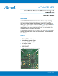
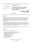
1
User Manual USB Radio Sticks deRFusb-23E00 deRFusb-23E00 JTAG deRFusb-23E06 deRFusb-23E06 JTAG deRFusb-13E00 deRFusb-13E00 JTAG deRFusb-13E06 deRFusb-13E06 JTAG Document Version V1.2 2012-07-31 User Manual Version 1.2 2012-07-31 USB radio sticks deRFusb Table of contents 1. Overview ......................................................................................................................... 6 2. Applications ..................................................................................................................... 7 3. Features .......................................................................................................................... 7 4. Assembling Options......................................................................................................... 9 4.1. USB stick for 2.4 GHz application ........................................................................... 9 4.2. USB stick for Sub-GHz application ....................................................................... 10 5. Technical data ............................................................................................................... 11 6. Mechanical size ............................................................................................................. 15 7. Application environment ................................................................................................ 16 8. Pin assignment .............................................................................................................. 17 9. On-board transceiver ..................................................................................................... 20 9.1. General transceiver description ............................................................................ 20 9.2. Internal transceiver connection to the MCU .......................................................... 21 10. On-board components and peripherals.......................................................................... 22 10.1. Clock .................................................................................................................. 22 10.2. Programmable LEDs ............................................................................................ 22 10.3. ERASE and VCC pins .......................................................................................... 23 10.4. On-board flash (option) ......................................................................................... 23 10.4.1. Mass Storage Device example .................................................... 23 10.5. Coaxial connector ................................................................................................. 26 11. Programming ................................................................................................................. 27 www.dresden-elektronik.de Page 2 of 36 User Manual Version 1.2 2012-07-31 USB radio sticks deRFusb 12. Pre-flashed firmware ..................................................................................................... 27 12.1. No firmware .......................................................................................................... 27 12.2. Wireless UART firmware ...................................................................................... 27 12.2.1. Step-by-Step instructions for Windows ........................................ 28 12.2.2. Step-by-Step instructions for Linux .............................................. 29 13. Radio certification .......................................................................................................... 30 13.1. United States (FCC) ............................................................................................. 30 13.2. European Union (ETSI) ........................................................................................ 31 14. Ordering information ...................................................................................................... 33 15. Revision notes ............................................................................................................... 35 16. References .................................................................................................................... 35 www.dresden-elektronik.de Page 3 of 36 User Manual Version 1.2 2012-07-31 USB radio sticks deRFusb Document history Date Version Description 2011-06-29 1.0 Initial version 2011-07-01 1.1 Update - Certification 2.4 GHz USB radio stick, temperature range, radio data 2012-07-16 1.2 Update - Technical data, mechanical size, programming, certification information added - Options overview, application environment, programmable LEDs, clock, pre-flashed firmware, on-board flash, coaxial connector information added Author / Check / Release Firm Division / Name Author DE Div. / APA Check DE Div. / ML Release www.dresden-elektronik.de Page 4 of 36 User Manual Version 1.2 2012-07-31 USB radio sticks deRFusb Abbreviations Abbreviation Description 802.15.4 IEEE 802.15.4-standard, applicable to low-rate wireless Personal Area Network ADC Analog to Digital Converter AES Advanced Encryption Standard CE (Applications) - Consumer Electronics DAC Digital to Analog Converter DBGU Debug Unit eMMC embedded Multimedia Card ETSI European Telecommunications Standards Institute FCC Federal Communications Commission GPIO Generals Purpose Input Output IC (Certification) - Industry Canada ISM Industrial, Scientific and Medical frequency band JTAG Joint Test Action Group MAC Medium Access Control MCU, µC Microcontroller Unit MMC Multimedia Card MSD Mass Storage Device PCB Printed Circuit Board PER Packet Error Rate (measurement) PWM Pulse Width Modulation RF Radio Frequency SPI Serial Peripheral Interface TRX Transceiver TWI Two-Wire Serial Interface UART Universal Asynchronous Receiver Transmitter U.FL Miniature coaxial RF connector for high-frequency signals USART Universal Synchronous/Asynchronous Receiver Transmitter USB Universal Serial Bus WPAN Wireless Personal Area Network WSN Wireless Sensor Networks www.dresden-elektronik.de Page 5 of 36 User Manual Version 1.2 2012-07-31 USB radio sticks deRFusb 1. Overview The USB radio sticks by dresden elektronik provide access to the world of IEEE 802.15.4™ technology by being the gateway to almost any IEEE 802.15.4 Wireless Sensor Networks. Such gateways can be used for monitoring, sniffing or control of wireless ZigBee® or 6LoWPAN networks and are easily adoptable to custom applications due to the available free stack software. The compact designed USB radio sticks deRFusb-23E00 and deRFusb-13E00 contain a powerful CORTEX-M3 microcontroller with 256 kB high-speed flash. Additional 2GB flash memory to store user defined data is provided using the USB radio sticks deRFusb-23E06 and deRFusb-13E06, it is usable as mass storage device. Depending on the transmission frequency of 2.4 GHz - deRFusb-23E00/06/JTAG - or 868/915 MHz - deRFusb-13E00/06/JTAG - the ATMEL low-power transceivers AT86RF231 or alternatively AT86RF212 are integrated. They provide a complete radio transceiver interface between the antenna and the microcontroller and an extended functional range such as a 128-bit AES hardware engine to ensure data security. For development the USB radio sticks provide a programming and debugging interface to the user, by default via native USB. For programming via JTAG, the board options deRFusb23E00 JTAG, deRFusb-23E06 JTAG, deRFusb-13E00 JTAG and deRFusb-13E06 JTAG are advised. www.dresden-elektronik.de Page 6 of 36 User Manual Version 1.2 2012-07-31 USB radio sticks deRFusb 2. Applications The main applications for the USB radio sticks deRFusb-23E00/06/JTAG and deRFusb13E00/06/JTAG are: 2.4 GHz and Sub-GHz range IEEE 802.15.4 ZigBee Pro ZigBee RF4CE ZigBee IP 6LoWPAN ISA100.11a Wireless Sensor Networks (WSN) Industrial and home controlling and monitoring Gateway to other network technologies via PC or laptop 3. Features The 2.4 GHz USB radio sticks deRFusb-23E00/JTAG and deRFusb-23E06/JTAG offer the following features: Compact size (in case): 71.0 x 23.0 x 8.7 mm USB powered 3 free programmable status LEDs (red, yellow, green) RF shielding Debugging/programming interfaces: 1 x DBGU and 1 x JTAG with 10-pin connector assembly option, native USB On-board transceiver and chip ceramic antenna 2.4 GHz Option: on-board 2 GB flash Certification: FCC certified, conformity ETSI/CE The block diagram (Figure 1) below shows layout and interaction of the main deRFusb23E00/06/JTAG components: Figure 1: Block diagram deRFusb-23E00/06/JTAG www.dresden-elektronik.de Page 7 of 36 User Manual Version 1.2 2012-07-31 USB radio sticks deRFusb The Sub-GHz USB radio sticks deRFusb-13E00/JTAG and deRFusb-13E06/JTAG offer similar features: Compact size (in case): 71.0 x 23.0 x 8.7 mm USB powered 3 free programmable status LEDs (red, yellow, green) RF shielding Debugging/programming interfaces: 1 x DBGU and 1 x JTAG with 10-pin connector assembly option, native USB On-board transceiver and chip ceramic antenna Sub-GHz Option: on-board 2 GB flash Conformity ETSI/CE Layout and interaction of the main deRFusb-13E00/06/JTAG components is shown in Figure 2. Figure 2: Block diagram deRFusb-13E00/06/JTAG www.dresden-elektronik.de Page 8 of 36 User Manual Version 1.2 2012-07-31 USB radio sticks deRFusb 4. Assembling Options This section gives a short overview of the different available USB stick options and their assembly parts. The basic assembly and design options of the USB radio sticks are: 10-pin connector 2 GB flash 4.1. USB stick for 2.4 GHz application The 2.4 GHz USB stick is available with an optional 10-pin connector and an optional 2 GB flash memory. In Figure 3 and Figure 4 the deRFusb-23E00 JTAG device is imaged. The RF shielding covers the microcontroller, the transceiver, the quartz crystals and all necessary passive components. USB plug type A 2.4 GHz chip ceramic antenna RF shielding Figure 3: Top view deRFusb-23E00 JTAG Option: 2 GB flash memory (not shown in the figure) three status LEDs Option: 10-pin connector for JTAG and debug Figure 4: Bottom view deRFusb-23E00 JTAG www.dresden-elektronik.de Page 9 of 36 User Manual Version 1.2 2012-07-31 4.2. USB radio sticks deRFusb USB stick for Sub-GHz application The Sub-GHz USB stick is available with an optional 10-pin connector and an optional 2 GB flash memory. In Figure 5 and Figure 6 the deRFusb-13E00 JTAG device is imaged. The RF shielding covers the microcontroller, the transceiver, the quartz crystals and all necessary passive components. USB plug type A Sub-GHz chip ceramic antenna RF shielding Figure 5: Top view deRFusb-13E00 JTAG Option: 2 GB flash memory (not shown in the figure) three status LEDs Option: 10-pin connector for JTAG and debug Figure 6: Bottom view deRFusb-13E00 JTAG www.dresden-elektronik.de Page 10 of 36 User Manual Version 1.2 2012-07-31 USB radio sticks deRFusb 5. Technical data Table 1: Mechanical data Mechanical Radio module Size (length x width x height) 71.0 x 23.0 x 8.7 mm (in case) 63.5 x 19.0 x 5.5 mm (without case) 63.5 x 19.0 x 9.5 mm (with JTAG, without case) Weight 13 g (in case) Connectors USB Plug type A 10-pin connector option ‘JTAG’ 2 x 5 pins, 1.27 mm (50 mil) pitch Table 2: Environment Temperature and humidity Operating temperature range Parameter Min Twork Operating humidity range Storage temperature range Tstorage Typ Max Unit -20 +70 °C 25 80 % r.H. -40 +85 °C Table 3: Electrical data Electrical (Supply voltage VUSB = 5.0V) Parameter Min Typ Max Unit Supply voltage VUSB 4.5 5.0 5.5 V Current consumption1 ITXon (TX_PWR = 0x00) 51 mA ITXoff 32 mA IRXon 45 mA 1 valid for deRFusb-23E00 / deRFusb-23E00 JTAG / deRFusb-13E00 / deRFusb-13E00 JTAG, see Table 5 for current consumption of USB sticks with external flash memory www.dresden-elektronik.de Page 11 of 36 User Manual Version 1.2 2012-07-31 USB radio sticks deRFusb Table 4: Quartz crystal properties Quartz crystal Parameter MCU crystal Min Typ Max Unit Frequency 18.432 MHz Frequency tolerance +/- 30 ppm Load capacitance 16 Transceiver crystal Frequency Frequency tolerance Load capacitance pF 16.000 MHz +/-10 ppm 9 pF Table 5: External Flash option External flash (Supply voltage VUSB = 5.0V) Parameter Storage size2 Min Typ Max Unit 2 GB Read/Burst 908 kB/s Read 882 kB/s Write/Burst 178 kB/s Write 192 kB/s Current Auto Sleep 32 mA consumption3 Sleep (CMD5) 32 mA (while MCU = Idle Read/Burst and TRX = Off) Read 53 mA 58 mA Write/Burst 87 mA Write 88 mA RW speed 2 2 GB = 2000 MB = 2.000.000 kB 3 valid for deRFusb-23E06 / deRFusb-23E06 JTAG / deRFusb-13E06 / deRFusb-13E06 JTAG www.dresden-elektronik.de Page 12 of 36 User Manual Version 1.2 2012-07-31 USB radio sticks deRFusb Table 6: Radio data of deRFusb-23E00/06/JTAG Radio 2.4 GHz (Supply voltage VUSB = 5.0V) Parameter / feature Antenna Min Type Gain Typ Line of sight Frequency range5 PHY_CC_CCA = 0x0B...0x1A Channels PHY_CC_CCA = 0x0B...0x1A Transmitting power conducted TX_PWR = 0x00 Unit Chip ceramic -0.2 Diversity Range4 Max +0.5 +0.9 dBi (peak) 240 m 2480 MHz +3.6 dBm No >200 2405 16 +2.8 +3.0 Receiver sensitivity Data Rate = 250kBit/s Data Rate = 500kBit/s Data Rate = 1000kBit/s Data Rate = 2000kBit/s - 97 -93 -90 -89 dBm dBm dBm dBm Data rate (gross) 250 500 1000 2000 kBit/s kBit/s kBit/s kBit/s TRX_CTRL_2 = 0x00 TRX_CTRL_2 = 0x01 TRX_CTRL_2 = 0x02 TRX_CTRL_2 = 0x03 4 Measured while device plugged into laptop standing on a tripod with a height of 1.4 meters above ground level and PER≤1% 5 Operating the transmitter at channel 26 requires to ensure a duty cycle ≤29% www.dresden-elektronik.de Page 13 of 36 User Manual Version 1.2 2012-07-31 USB radio sticks deRFusb Table 7: Radio data of deRFusb-13E00/06/JTAG Radio Sub-GHz (Supply voltage VUSB = 5.0V) Parameter / feature Antenna Min Typ Max Type Chip ceramic Gain - 0.7 Diversity Line of sight (915MHz) Line of sight (868MHz) >100 >200 Frequency range PHY_CC_CCA = 0x00 PHY_CC_CCA = 0x01...0x0A 868.3 PHY_CC_CCA = 0x00 PHY_CC_CCA = 0x01...0x0A Transmitting power conducted TX_PWR = 0x00 @ 915MHz TX_PWR = 0x00 @ 868MHz dBi (peak) No Range6 Channels Unit 906 120 220 m m 924 MHz MHz + 9.0 + 5.0 dBm dBm 1 10 Receiver sensitivity Data Rate = 20kBit/s Data Rate = 40kBit/s Data Rate = 250kBit/s -106 -104 -97 dBm dBm dBm Data rate (gross) TRX_CTRL_2 = 0x00 TRX_CTRL_2 = 0x08 TRX_CTRL_2 = 0x09 TRX_CTRL_2 = 0x2A 20 100 200 400 kBit/s kBit/s kBit/s kBit/s TRX_CTRL_2 = 0x04 TRX_CTRL_2 = 0x0C TRX_CTRL_2 = 0x0D TRX_CTRL_2 = 0x2E 40 250 500 1000 kBit/s kBit/s kBit/s kBit/s 6 Measured while device plugged into laptop standing on a tripod with a height of 1.4 meters above ground level and PER≤1% www.dresden-elektronik.de Page 14 of 36 User Manual Version 1.2 2012-07-31 USB radio sticks deRFusb 6. Mechanical size The outer PCB dimensions are the same and not depending on the different USB board options, for details refer to Table 1. The example shown in Figure 7 is the deRFusb-13E00 / deRFusb-13E06 radio stick; placed in the case the mechanical size is 71.0 x 23.0 x 8.7 mm (L x W x H). All dimensions are in millimeters. Figure 7: Mechanical dimension top view The 10-pin connector dimension is shown in Figure 8 as part X2; the displayed antenna type is the 2.4 GHz USB stick one. Figure 8: Mechanical dimension side view www.dresden-elektronik.de Page 15 of 36 User Manual Version 1.2 2012-07-31 USB radio sticks deRFusb 7. Application environment The USB sticks are designed to connect an IEEE 802.15.4 network with the PC and laptop environment. Today there are different variants of USB ports on laptop and PC devices. The USB stick dimension is optimized to plug other USB devices in adjacent ports especially in horizontal or vertical designed USB hubs. Generally, the radiation pattern of RF devices depends on the placement and the application environment. The test measurement and certification process was done with a plugged USB stick on the side of an USB port of a laptop while the display was open. It is recommended to plug the USB stick sideways at an USB port of a laptop, if applicable. The use of application setups like USB hubs or USB extension cables may result in a lower transmit and receive range. The USB stick can only be directly plugged into type A ports; into a laptop, PC or hub. Figure 9: Laptop USB port type A www.dresden-elektronik.de Page 16 of 36 User Manual Version 1.2 2012-07-31 USB radio sticks deRFusb 8. Pin assignment The USB stick has a type A USB plug and an optional 10-pin connector in 1.27 mm pitch for programming via JTAG interface and tracing via UART. This connector is directly accessible from the USB stick bottom side, see Figure 10. The internal and external signal connection to the MCU and transceiver is shown in Table 8. The external available signals are described in Table 9. 2 10 1 9 1.27 mm (50 mil) pitch Figure 10: Pin assignment of optional 10-pin connector www.dresden-elektronik.de Page 17 of 36 User Manual Version 1.2 2012-07-31 USB radio sticks deRFusb Table 8: Pin assignment of deRFusb-23E00/06/JTAG and deRFusb-13E00/06/JTAG µC Pin Signal name Function Comments USB connector 56 DDM USB DM 57 DDP USB DP 10-pin connector (only available with option ‘JTAG’) 53 PB7/TCK/SWCLK JTAG TCK Connector pin 1 - GND Connector pin 2 49 PB5/TWCK1/PWML0/WKUP13/TDO JTAG TDO Connector pin 3 - VCC Connector pin 4 51 PB6/TMS/SWDIO JTAG TMS Connector pin 5 39 NRST /Reset Connector pin 6 - VCC 30 PA9/URXD0/NPCS1/PWMFI0 Debug RXD Connector pin 8 33 PB4/TWD1/PWMH2/TDI JTAG TDI Connector pin 9 29 PA10/UTXD0/NPCS2 Debug TXD Connector pin 10 Connector pin 7 Miscellaneous 13 PA19/RK/PWML0/A15/AD2 LED1 red 9 PA17/TD/PCK1/PWMH3/AD0 LED2 yellow 10 PA18/RD/PCK2/A14/AD1 LED3 green 35 PA5/RXD0/NPCS3 Hardware ID1 34 PA6/TXD0/PCK0 Hardware ID2 32 PA7/RTS0/PWMH3/XIN32 Hardware ID3 2 GB flash memory (only available with option ‘06’) 42 MCDA0 ext. Flash Data 0 52 MCDA1 ext. Flash Data 1 26 MCDA2 ext. Flash Data 2 37 MCDA3 ext. Flash Data 3 38 MCCDA ext. Flash Command 41 MCCK ext. Flash Clock Erase pin 55 PB12/PWML1/ERASE www.dresden-elektronik.de See Section 11 Page 18 of 36 User Manual Version 1.2 2012-07-31 USB radio sticks deRFusb Table 9: Signal description list Signal name Function Type Active level Comments Power - USB connector DDM USB Full Speed Data – DDP USB Full Speed Data + Analog Digital JTAG TCK Test Clock Input On-board Pull-up TDI Test Data In Input On-board Pull-up TDO Test Data Out Output TDM Test Mode Select Input Microcontroller Reset I/O URXD0 UART Receive Data Input UTXD0 UART Transmit Data Output On-board Pull-up Reset RSTN Low Pull-Up resistor UART0 www.dresden-elektronik.de Page 19 of 36 User Manual Version 1.2 2012-07-31 USB radio sticks deRFusb 9. On-board transceiver The main difference between the deRFusb-23E00/06/JTAG and the deRFusb13E00/06/JTAG USB radio sticks is the built-in 2.4 GHz or alternatively Sub-GHz transceiver in combination with the appropriate on-board chip antenna. The signal connection between MCU and transceiver is shown in Table 8. deRFusb-23E00/06/JTAG - AT86RF231 transceiver The low-power 2.4 GHz transceiver is designed for industrial and consumer IEEE 802.15.4, ZigBee, RF4CE, ISA100.11a and high data rate ISM applications. For details refer to [1] in the reference section. deRFusb-13E00/06/JTAG - AT86RF212 transceiver The low-power, low-voltage 800/900MHz transceiver is designed for low-cost IEEE 802.15.4, ZigBee and high data rate ISM applications available Europe and North America. For details refer to [2]. 9.1. General transceiver description These single-chip radio transceivers provide a complete radio transceiver interface between an antenna and a microcontroller. They comprise the analog radio transceiver and the digital modulation and demodulation including time and frequency synchronization and data buffering. The number of external components is minimized such that only the antenna, the crystal and decoupling capacitors are required. The bidirectional differential antenna pins are used for transmission and reception, thus no external antenna switch is needed. An internal 128 byte RAM for RX and TX buffers the data to be transmitted or the received data. Two on chip low dropout voltage regulators provide the internal analog and digital 1.8 V supply. The transceivers further contain comprehensive hardware-MAC support (Extended Operating Mode) and a security engine (AES) to improve the overall system power efficiency and timing. www.dresden-elektronik.de Page 20 of 36 User Manual Version 1.2 2012-07-31 9.2. USB radio sticks deRFusb Internal transceiver connection to the MCU The internal circuitry between MCU and transceiver is described in Table 10. Table 10: Transceiver connection µC Pin TRX Pin Signal name Function Comments Internal transceiver interface 20 10 PA15/TF/TIOA1/PWML3 RXTS/DIG2 1. Antenna Diversity RF switch control 2. RX Frame Time Stamping 11 11 PA21/RXD1/PCK1/AD8 SLP-TR Controls sleep, transmit start, receive states 21 19 PA14/SPCK/PWMH3 SCK SPI Serial Clock 27 20 PA12/MISO/PWMH1 MISO Master In / Slave Out 22 22 PA13/MOSI/PWMH2 MOSI Master Out / Slave In 28 23 PA11/NPCS0/PWMH0 SELN SPI Select 47 24 PA1/PWMH1/TIOB0/A18 IRQ 1. Interrupt request signal 2. Frame Buffer Empty Indicator 23 8 PA24/RTS1/PWMH1/A20 RST Transceiver Reset 36 17 PA4/TWCK0/TCLK0 CLKM Master clock signal output, internal lowpass filter assembled www.dresden-elektronik.de Page 21 of 36 User Manual Version 1.2 2012-07-31 USB radio sticks deRFusb 10. On-board components and peripherals This section describes the important on-board peripherals: Clock, status LEDs as well as memory and access options to the board. 10.1. Clock The USB sticks contain an external on-board 18.432 MHz 30 ppm quartz crystal for the MCU and a 16.000MHz 10ppm quartz crystal for the transceiver. For optimum RF timing characteristics it is necessary to use a low tolerance crystal. The crystal assignment on the PCB is shown in Table 11. Table 11: Crystal assignment µC Pin TRX Pin Signal name Function Comments 61 - PB8/XOUT MCU crystal 62 - PB9/XIN 18.432MHz quartz crystal - 26 XTAL1 Transceiver crystal - 25 XTAL2 16.000MHz quartz crystal Clock 10.2. Programmable LEDs The USB sticks are assembled with three colored LEDs which are free programmable. Figure 11 shows the red, yellow and green status LEDs. They are located on the bottom side of the PCB. The internal connection between MCU and LED is listed in Table 12. green, yellow, red LED Figure 11: ERASE pins and status LEDs www.dresden-elektronik.de Page 22 of 36 User Manual Version 1.2 2012-07-31 USB radio sticks deRFusb Table 12: Internal connection of LEDs µC Pin Signal name Function Comments LEDs 13 PA19 LED1 red 9 PA17 LED2 yellow 10 PA18 LED3 green 10.3. ERASE and VCC pins The ERASE pin (see Figure 11) is used to reinitialize the MCU flash content - and some of its NVM (Non-Volatile Memory) bits - to an erased state. The flash is transferred to its original state. For more details please refer to [3]. To perform a flash erase operation the pin has to be tied high longer than 220 ms while the USB stick is connected to the PC. Notes: By electrically connecting the two test points ERASE and VCC the internal MCU flash memory will be deleted. The firmware as originally available in the board’s delivery condition (see Section 12.2) will be destroyed. Caution: the USB sticks have the MAC address pre-flashed into the on chip Flash during the production process. Erasing the flash via the ERASE method will also erase this pre-flashed information which some firmware may require for proper operation. Please make sure your firmware will not be affected by the ERASE method before using it. If you erased the pre-flashed information accidentally please read the ‘User Manual deRFusb Firmware Update‘ [3] to recreate the MAC address information. Work carefully when handling the board! The moisture of your fingers’ skin may be sufficient under certain conditions to destroy the internal flash content. 10.4. On-board flash (option) A 2 GB flash memory (iNand SDIN5D2-2G by Sandisk) to store user defined data is optionally available using the deRFusb-23E06/JTAG and deRFusb-13E06/JTAG USB radio sticks. This flash memory is typically applied as mass storage device (MSD) for user data. It works like a Multimedia Card (MMC). Possible data bit modes are 1bit and 4bit. The flash is equipped with a memory controller and has a NAND flash architecture. It complies with eMMC Specification Version 4.4. The technical data of the assembled flash is listed in Table 5. 10.4.1. Mass Storage Device example An example to use the flash as Mass Storage Device in Windows® can be found on the dresden elektronik webpage getting started documentation in section 'Native Examples’. The steps how to use the USB stick flash as MSD are described here. Currently the examples can only be run with the devices deRFusb-23E06 and deRFusb-13E06. www.dresden-elektronik.de Page 23 of 36 User Manual Version 1.2 2012-07-31 USB radio sticks deRFusb 1. Following the programming instructions in Section 11 and flash the device with the ‘deRF_MSD’ native example. 2. Plug in your device into PC or laptop. 3. A new hard disk drive will appear, see Figure 12. Figure 12: new HDD 4. The MSD should be formatted for proper work. Choose the FAT32 file system and, if necessary, a new volume name (Figure 13). The option ‘fast formatting’ is useful. Figure 13: Formatting the MSD www.dresden-elektronik.de Page 24 of 36 User Manual Version 1.2 2012-07-31 USB radio sticks deRFusb 5. Now the MSD will be displayed correctly with its volume name and the storage size (Figure 14). Figure 14: MSD with volume name and storage size 6. The MSD is ready for work. Data can be stored on the MSD. www.dresden-elektronik.de Page 25 of 36 User Manual Version 1.2 2012-07-31 USB radio sticks deRFusb 10.5. Coaxial connector The USB sticks have a footprint for assembling a coaxial connector to connect the device with an external antenna or for spectral measurements. Attention: A coaxial connector is only applicable for test and measurement. CE conformity and FCC certification become invalid! At first the couple capacitor has to be removed and placed to the shared footprint. It is possible to use the removed one. If a new capacitor is required use 22 pF package 04027 for 2.4 GHz applications and 100 pF package 0402 for Sub-GHz. Then place a 10 kOhms 0402 resistor on the appropriate footprint next to coaxial connector. At last place a U.FL coaxial connector, like U.FL-R-SMT-1(01) by Hirose. All soldering actions can be done by hand. The use of a forceps and a microscope are maybe useful. Remove capacitor Place capacitor Place U.FL Place resistor Figure 15: Footprint for U.FL coaxial connector 7 Package 0402 (1005 metric) = 1.0 x 0.5 mm www.dresden-elektronik.de Page 26 of 36 User Manual Version 1.2 2012-07-31 USB radio sticks deRFusb 11. Programming The programming procedures are described in the documentation ‘User Manual deRFusb Firmware Update’ [3], which is available as PDF document on dresden elektronik webpage. It describes step-by-step the update process of the USB sticks, the required software and hardware for programming via USB or JTAG and the driver installation on different operating systems. 12. Pre-flashed firmware The USB sticks are available with different pre-flashed firmware depending on the hardware configuration. A colored marker is placed on the PCB for differentiation of the delivered firmware. 12.1. No firmware red marker These USB sticks have a red marker and will be delivered within a plastic enclosure. A custom firmware can be flashed via USB interface. See Section 11 for more details. 12.2. Wireless UART firmware green marker USB sticks with pre-flashed wireless UART firmware have a light green marker and will be delivered with an attached plastic enclosure. Working with the wireless UART requires a terminal program like HyperTerminal or any other. The Wireless UART application example is described in Section 12.3.1 for Windows and Section 12.3.2 for Linux. 12.3. JTAG analyzer firmware (deRFusb-23E00 JTAG) blue marker www.dresden-elektronik.de Page 27 of 36 User Manual Version 1.2 2012-07-31 USB radio sticks deRFusb The analyzer version of the deRFusb23E00 JTAG USB radio stick is optimally matched for Perytons’ professional network and protocol analysis software. With the valid 30-day Trial licence you can monitor network structures as well as observe data flows and runtime performance in detail without additional effort. Especially during the development phase this protocol analysis software will serve as an essential and valuable tool. Compared to other analyzer tools the dresden elektronik USB radio stick facilitates synchronous sniffing of all 16 channels. The analyzer is operating with an accuracy of 1µs. All three Perytons’ software versions are supported for the 802.15.4 radio range: Version Description Number of required USB sticks Peryton-S Single-channel analyzer 1 Peryton-D Like S with antenna diversity 2 Peryton-M Multi-channel analyzer Channels + 1 12.3.1. Step-by-Step instructions for Windows 1. Plug in two USB sticks with pre-flashed wireless UART firmware into your PC(s) and/or laptop(s). 2. If you connect first time to a PC, you will be asked to install the driver for the USB device. The USB drivers are available on dresden elektronik homepage. Refer to the products web shop site. 3. The Windows device manager tells you which virtual COM port (serial port) is assigned to each USB stick. 4. If you know both COM ports, then open two terminal program sessions. 5. On each terminal session you have to set up the corresponding COM port. Baud rate, data bits, parity and stop bit settings are unimportant. 6. If all is set up correctly, simply type any character into one terminal window and you can see this character on the other terminal window (this also runs vice versa). 7. The character is received by the USB stick and transferred wireless to the other USB stick, that sends the received character to the own terminal program, see Figure 16. Figure 16: Wireless UART terminal session www.dresden-elektronik.de Page 28 of 36 User Manual Version 1.2 2012-07-31 12.3.2. USB radio sticks deRFusb Step-by-Step instructions for Linux In order to use the serial USB port of deRFusb products with Linux the following steps have to be carried out. The user is either required to have root privileges or use sudo. 1. Use the following commands to unload the relevant kernel modules: rmmod usbserial 2. Create and open the file /etc/modprobe.d/dresden_elektronik.conf. If the directory /etc/modprobe.d/ doesn't exist edit the file /etc/modprobe.conf or /etc/modprobe.conf.local instead. Currently it is not possible to have multiple device types running at the same time. The limit is one device for ftdi_sio and one for usbserial module. All devices will be included in the mainline kernel and lift this limitation. The applicable kernel version is not yet known. Add the following lines to the file: #deRFusb23E00 #options usbserial vendor=0x1cf1 product=0x001a #deRFusb13E00 #options usbserial vendor=0x1cf1 product=0x001b #deRFusb13E06 #options usbserial vendor=0x1cf1 product=0x0027 #deRFusb23E06 #options usbserial vendor=0x1cf1 product=0x0025 3. Uncomment the options line for your device. This is also valid for USB sticks with JTAG connector. Example for a deRFusb: #deRFusb23E00 options usbserial vendor=0x1cf1 product=0x001a 4. Reload the kernel modules unloaded in Step 1 modprobe usbserial 5. After connecting the device to PC or laptop USB port a new device should appear in the directory /dev. The device name is either /dev/ttyUSBx or /dev/ACMx there x is a number from 0-9. 6. Open two terminal program sessions for the devices. 7. If all is set up correctly, simply type any character into one terminal and you can see this character on the other terminal (this also works vice versa). 8. The character is received by the USB stick and transferred over air to the other USB stick, who sends the received character to the own terminal program. www.dresden-elektronik.de Page 29 of 36 User Manual Version 1.2 2012-07-31 USB radio sticks deRFusb 13. Radio certification 13.1. United States (FCC) The deRFusb-23E00/06/JTAG and deRFusb-13E00/06/JTAG USB radio sticks comply with the requirements of FCC part 15 B and part 15 C. The FCC certification for deRFusb-13E00/06/JTAG is pending. To fulfill FCC Certification requirements, an OEM manufacturer must comply with the following regulations: The modular transmitter must be labeled with its own FCC ID number, and, if the FCC ID is not visible when the module is installed inside another device, the outside of the device into which the module is installed must also display a label referring to the enclosed module. This exterior label can use wording such as the following. Any similar wording that expresses the same meaning may be used. Sample label for USB radio stick deRFusb-23E00, deRFusb-23E06, deRFusb-23E00 JTAG and deRFusb-23E06 JTAG: FCC-ID: XVV-ARM323E00 This device complies with Part 15 of the FCC Rules. Operation is subject to the following two conditions: (1) this device may not cause harmful interference, and (2) this device must accept any interference received, including interference that may cause undesired operation. Note: The deRFusb-23E00 JTAG, deRFusb-23E06 and deRFusb-23E06 JTAG USB radio sticks fulfill a Permissive Change Class 1 regarding to FCC Section 2.1043 and complies with the requirements of FCC part 15. The Original Equipment Manufacturer (OEM) must ensure that the OEM modular transmitter is labeled with its own FCC ID number. This includes a clearly visible label on the outside of the final product enclosure that displays the contents shown below. If the FCC ID is not visible when the equipment is installed inside another device, the outside of the device into which the equipment is installed must also display a label referring to the enclosed equipment. This equipment complies with Part 15 of the FCC Rules. Operation is subject to the following two conditions: (1) this device may not cause harmful interference, and (2) this device must accept any interference received, including interference that may cause undesired operation (FCC 15.19). The internal / external antenna(s) used for this mobile transmitter must provide a separation distance of at least 20 cm from all persons and must not be co-located or operate in conjunction with any other antenna or transmitter. Installers must be provided with antenna installation instructions and transmitter operating conditions for satisfying RF exposure compliance. This device is approved as a mobile device with respect to RF exposure compliance, and may only be marketed to OEM installers. Use in portable exposure conditions (FCC 2.1093) requires separate equipment authorization. www.dresden-elektronik.de Page 30 of 36 User Manual Version 1.2 2012-07-31 USB radio sticks deRFusb Modifications not expressly approved by this company could void the user's authority to operate this equipment (FCC section 15.21). This equipment has been tested and found to comply with the limits for a Class B digital device, pursuant to Part 15 of the FCC Rules. These limits are designed to provide reasonable protection against harmful interference in a residential installation. This equipment generates, uses and can radiate radio frequency energy and, if not installed and used in accordance with the instructions, may cause harmful interference to radio communications. However, there is no guarantee that interference will not occur in a particular installation. If this equipment does cause harmful interference to radio or television reception, which can be determined by turning the equipment off and on, the user is encouraged to try to correct the interference by one or more of the following measures: Reorient or relocate the receiving antenna Increase the separation between the equipment and receiver Connect the equipment into an outlet on a circuit different from that to which the receiver is connected Consult the dealer or an experienced radio/TV technician for help Channel 26 issue The built in transceiver AT86RF231 has an issue considering the transmitted power in the last channel 26. Because of the restricted band in United States that starts at 2483.5 MHz the limit for spurious emissions are stricter. The best solution to fulfill the FCC requirements is to set a maximum duty cycle of 29% for channel 26. This value is related to a 100ms period, which means that the transceiver can transmit 29ms within a period of 100ms. This leads to a correction factor according to ANSI C63.10-2009 (clause 4.4) that decrease the measured transmit value below the limit and to provide a FCC conform application. 13.2. European Union (ETSI) The deRFusb-23E00/06/JTAG and deRFusb-13E00/06/JTAG USB radio sticks have been tested compliant for use in the European Union countries according to EN300328-V1.7.1 and EN301489-1-V1.8.1. If the deRFusb-23E00/06/JTAG and deRFusb-13E00/06/JTAG USB radio sticks are incorporated into a product, the manufacturer must ensure compliance of the final product to the European harmonized EMC and low-voltage/safety standards. A Declaration of Conformity must be issued for each of these standards and kept on file as described in Annex II of the R&TTE Directive. The manufacturer must maintain a copy of the deRFusb-23E00/06/JTAG and deRFusb13E00/06/JTAG USB radio sticks documentation and ensure the final product does not exceed the specified power ratings, antenna specifications, and/or installation requirements as specified in the user manual. If any of these specifications are exceeded in the final product, a submission must be made to a notified body for compliance testing to all required standards. www.dresden-elektronik.de Page 31 of 36 User Manual Version 1.2 2012-07-31 USB radio sticks deRFusb The “CE“ marking must be affixed to a visible location on the OEM product. The CE mark shall consist of the initials "CE" taking the following form: If the CE marking is reduced or enlarged, the proportions given in the above graduated drawing must be respected. The CE marking must have a height of at least 5mm except where this is not possible on account of the nature of the apparatus. The CE marking must be affixed visibly, legibly, and indelibly. More detailed information about CE marking requirements you can find at "DIRECTIVE 1999/5/EC OF THE EUROPEAN PARLIAMENT AND OF THE COUNCIL" on 9 March 1999 at section 12. www.dresden-elektronik.de Page 32 of 36 User Manual Version 1.2 2012-07-31 USB radio sticks deRFusb 14. Ordering information The product name includes the following information: deRF xxxx - x x x xx x Revision Features Size Flash Memory Frequency Range Product / Chipset Table 13: Product name code Product name code Information Code Explanation Product / Chipset usb USB radio stick Frequency range 1 868/915 MHz 2 2.4 GHz Flash memory 3 256 kB Size E USB stick Features 00 chip antenna 06 chip antenna, 2 GB flash On-board 00 JTAG chip antenna 10-pin connector 06 JTAG chip antenna, 2 GB flash JTAG + DEBUG 10-pin connector www.dresden-elektronik.de Comments On-board JTAG + DEBUG Page 33 of 36 User Manual Version 1.2 2012-07-31 USB radio sticks deRFusb Table 14: Ordering information Ordering information Part number Product name Comments BN-031805 deRFusb-23E00 NO FW USB radio stick for 2.4 GHz delivered with a fitting case no pre-flashed firmware BN-033202 deRFusb-23E00 JTAG WUART FW USB radio stick for 2.4 GHz with assembled JTAG connector pre-flashed with Wireless UART firmware BN-031075 deRFusb-23E06 NO FW BN-033203 deRFusb-23E06 JTAG WUART FW USB radio stick for 2.4 GHz with 2 GB flash with assembled JTAG connector pre-flashed with Wireless UART firmware BN-031807 deRFusb-13E00 NO FW BN-033206 deRFusb-13E00 JTAG WUART FW USB radio stick for Sub-GHz with assembled JTAG connector pre-flashed with Wireless UART firmware BN-031539 deRFusb-13E06 NO FW BN-033207 deRFusb-13E06 JTAG WUART FW USB radio stick for Sub-GHz with 2 GB flash with assembled JTAG connector pre-flashed with Wireless UART firmware BN-028337 SAM-ICE-Adapter www.dresden-elektronik.de USB radio stick for 2.4 GHz with 2 GB flash delivered with a fitting case no pre-flashed firmware USB radio stick for Sub-GHz delivered with a fitting case no pre-flashed firmware USB radio stick for Sub-GHz with 2 GB flash delivered with a fitting case no pre-flashed firmware program and debug interface adapter for USB radio sticks Page 34 of 36 User Manual Version 1.2 2012-07-31 USB radio sticks deRFusb 15. Revision notes Although the boards provide a CLKM connection from the radio transceiver to the micro controller, this connection is rarely used by any firmware. From performance measurements on the 2.4 GHz USB sticks deRFusb-23E00/06/JTAG this CLKM connection has a slight influence on the packet error rate in channel 26 resulting in less range and a higher packet error rate in general on this channel. Therefore we strongly recommend all users to check their firmware settings and ensure that the CLKM signal from the transceiver will be disabled in all situations. Up to now no other technical problems, malfunctions or critical issues are not known for the deRFusb-23E00/06/JTAG and deRFusb-13E00/06/JTAG USB radio sticks. 16. References [1] AT86RF212-ZU: AVR Low Power 700/800/900 MHz Transceiver for IEEE802.15.42006, IEEE802.15.4-2009, ZigBee, 6LoWPAN, and ISM Applications; Datasheet; 8186-MCU Wireless-02/10 [2] AT86RF231-ZU: AVR Low Power 2.4 GHz Transceiver for ZigBee, IEEE802.15.4, 6LoWPAN, RF4CE, SP100, WirelessHART, and ISM Applications; Datasheet; 8111C-MCU Wireless-09/09 [3] User Manual deRFusb Firmware Update, Version 1.3; 06/2012, http://www.dresdenelektronik.de www.dresden-elektronik.de Page 35 of 36 User Manual Version 1.2 2012-07-31 USB radio sticks deRFusb dresden elektronik ingenieurtechnik gmbh Enno-Heidebroek-Straße 12 01237 Dresden GERMANY Tel. +49 351 - 31850 0 Fax +49 351 - 31850 10 www.dresden-elektronik.de E-mail [email protected] Trademarks and acknowledgements • ZigBee® is a registered trademark of the ZigBee Alliance. • 802.15.4™ is a trademark of the Institute of Electrical and Electronics Engineers (IEEE). These trademarks are registered by their respective owners in certain countries only. Other brands and their products are trademarks or registered trademarks of their respective holders and should be noted as such. Disclaimer This note is provided as-is and is subject to change without notice. Except to the extent prohibited by law, dresden elektronik ingenieurtechnik gmbh makes no express or implied warranty of any kind with regard to this guide, and specifically disclaims the implied warranties and conditions of merchantability and fitness for a particular purpose. dresden elektronik ingenieurtechnik gmbh shall not be liable for any errors or incidental or consequential damage in connection with the furnishing, performance or use of this guide. No part of this publication may be reproduced, stored in a retrieval system, or transmitted in any form or any means electronic or mechanical, including photocopying and recording, for any purpose other than the purchaser’s personal use, without the written permission of dresden elektronik ingenieurtechnik gmbh. Copyright © 2012, dresden elektronik ingenieurtechnik gmbh. All rights reserved. www.dresden-elektronik.de Page 36 of 36