1
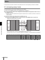
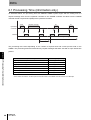
FOR
SEMI STANDARD-COMPATIBLE
CIDRW SYSTEM
USER'S MANUAL
CIDRW Controller
Model V700-L21
ID Link Unit
Model V700-L11
IDRW Head
Model V700-HMD13
Model V700-HMD11-1
ID Tag
Model V700-D23P41
OMRON Corporation
© OMRON Corporation 2000 All Right Reserved
Catalog No. Z214-E1-01B
Introduction
Thank you for purchasing the OMRON product.
To be able to operate the product safely and efficiently, carefully study this user's manual and get fully familiar
with the instruction in it before attempting to use the product. Keep this manual at hand for speedy reference
while operating, maintaining or servicing the equipment.
READ AND UNDERSTAND THIS DOCUMENT
Please read and understand this document before using the products. Please consult your OMRON representative if you have any questions or
comments.
WARRANTY
OMRON’s exclusive warranty is that the products are free from defects in materials and workmanship for a period of one year (or other period if
specified) from date of sale by OMRON.
OMRON MAKES NO WARRANTY OR REPRESENTATION, EXPRESS OR IMPLIED, REGARDING NON-INFRINGEMENT,
MERCHANTABILITY, OR FITNESS FOR PARTICULAR PURPOSE OF THE PRODUCTS. ANY BUYER OR USER ACKNOWLEDGES THAT
THE BUYER OR USER ALONE HAS DETERMINED THAT THE PRODUCTS WILL SUITABLY MEET THE REQUIREMENTS OF THEIR
INTENDED USE. OMRON DISCLAIMS ALL OTHER WARRANTIES, EXPRESS OR IMPLIED.
LIMITATIONS OF LIABILITY
OMRON SHALL NOT BE RESPONSIBLE FOR SPECIAL, INDIRECT, OR CONSEQUENTIAL DAMAGES, LOSS OF PROFITS OR
COMMERCIAL LOSS IN ANY WAY CONNECTED WITH THE PRODUCTS, WHETHER SUCH CLAIM IS BASED ON CONTRACT,
WARRANTY, NEGLIGENCE, OR STRICT LIABILITY.
In no event shall responsibility of OMRON for any act exceed the individual price of the product on which liability is asserted.
IN NO EVENT SHALL OMRON BE RESPONSIBLE FOR WARRANTY, REPAIR, OR OTHER CLAIMS REGARDING THE PRODUCTS UNLESS
OMRON’S ANALYSIS CONFIRMS THAT THE PRODUCTS WERE PROPERLY HANDLED, STORED, INSTALLED, AND MAINTAINED AND
NOT SUBJECT TO CONTAMINATION, ABUSE, MISUSE, OR INAPPROPRIATE MODIFICATION OR REPAIR.
SUITABILITY FOR USE
THE PRODUCTS CONTAINED IN THIS DOCUMENT ARE NOT SAFETY RATED. THEY ARE NOT DESIGNED OR RATED FOR ENSURING
SAFETY OF PERSONS, AND SHOULD NOT BE RELIED UPON AS A SAFETY COMPONENT OR PROTECTIVE DEVICE FOR SUCH
PURPOSES. Please refer to separate catalogs for OMRON's safety rated products.
OMRON shall not be responsible for conformity with any standards, codes, or regulations that apply to the combination of products in the
customer’s application or use of the product.
At the customer’s request, OMRON will provide applicable third party certification documents identifying ratings and limitations of use that apply
to the products. This information by itself is not sufficient for a complete determination of the suitability of the products in combination with the end
product, machine, system, or other application or use.
The following are some examples of applications for which particular attention must be given. This is not intended to be an exhaustive list of all
possible uses of the products, nor is it intended to imply that the uses listed may be suitable for the products:
• Outdoor use, uses involving potential chemical contamination or electrical interference, or conditions or uses not described in this document.
• Nuclear energy control systems, combustion systems, railroad systems, aviation systems, medical equipment, amusement machines, vehicles,
safety equipment, and installations subject to separate industry or government regulations.
• Systems, machines, and equipment that could present a risk to life or property.
Please know and observe all prohibitions of use applicable to the products.
NEVER USE THE PRODUCTS FOR AN APPLICATION INVOLVING SERIOUS RISK TO LIFE OR PROPERTY WITHOUT ENSURING THAT
THE SYSTEM AS A WHOLE HAS BEEN DESIGNED TO ADDRESS THE RISKS, AND THAT THE OMRON PRODUCT IS PROPERLY RATED
AND INSTALLED FOR THE INTENDED USE WITHIN THE OVERALL EQUIPMENT OR SYSTEM.
PERFORMANCE DATA
Performance data given in this document is provided as a guide for the user in determining suitability and does not constitute a warranty. It may
represent the result of OMRON’s test conditions, and the users must correlate it to actual application requirements. Actual performance is subject
to the OMRON Warranty and Limitations of Liability.
CHANGE IN SPECIFICATIONS
Product specifications and accessories may be changed at any time based on improvements and other reasons.
It is our practice to change model numbers when published ratings or features are changed, or when significant construction changes are made.
However, some specifications of the product may be changed without any notice. When in doubt, special model numbers may be assigned to fix
or establish key specifications for your application on your request. Please consult with your OMRON representative at any time to confirm actual
specifications of purchased products.
DIMENSIONS AND WEIGHTS
Dimensions and weights are nominal and are not to be used for manufacturing purposes, even when tolerances are shown.
ERRORS AND OMISSIONS
The information in this document has been carefully checked and is believed to be accurate; however, no responsibility is assumed for clerical,
typographical, or proofreading errors, or omissions.
PROGRAMMABLE PRODUCTS
OMRON shall not be responsible for the user’s programming of a programmable product, or any consequence thereof.
COPYRIGHT AND COPY PERMISSION
This document shall not be copied for sales or promotions without permission. This document is protected by copyright and is intended solely for
use in conjunction with the product. Please notify us before copying or reproducing this document in any manner, for any other purpose. If
copying or transmitting this document to another, please copy or transmit it in its entirety.
V700-L21
User's Manual
1
Introduction
Introduction Precaution
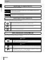
Meanings of Signal Words
The following signal words are used in this manual.
WARNING
Indicates a potentially hazardous situation which, if not avoided, will result in minor or
moderate injury, or may result in serious injury or death. Additionally, there may be
significant property damage.
CAUTION
Indicates a potentially hazardous situation which, if not avoided, may result in minor or
moderate injury or in property damage.
Meanings of Alert Symbols
The following alert symbols are used in this manual.
Indicates general prohibitions for which there is no spacific symbol.
Indicates instruction for the user to always connect the ground wire.
Indicates prohibition when there is a risk of minor injury from electrical shock or other
source if the product is disassembled.
Alert statements in this Manual
The following alert statements apply to the products in this manual. Each alert statement also appears at the
locations needed in this manual to attract your attention.
WARNING
This product is not designed to be used either directly or indirectly in applications that
detect human presence for the purpose of maintaining safety. Do not use this product
as a sensing device for protecting human lives.
CAUTION
Do not disassemble the Unit or touch the internal parts of the Unit while the power is
turned ON. Doing so may result in electric shock due to the high-voltage internal
parts.
The GR (frame ground) terminal is in the multi-connection port. Always ground the
multi-connection port to 100 Ω or less, regardless of whether it is used or not.
Performance may deteriorate if the port is not ground.
2
V700-L21
User's Manual
Introduction
To operate the CIDRW system more reliably and to allow the system to fully perform as designed, follow the
instructions below:
■ About environments of installation
Do not install or leave the product to a location such as:
• Location subjected to direct sunlight
• Location where corrosive gas, dust, metal dust, salty air is present
• Location where the operating temperature can exceed or drop below a range defined in the specification
Introduction Precautions for Correct Use
Precautions for Correct Use
• Location where temperature change is great, and can lead to dew condensation
• Location with higher humidity, and can lead to dew condensation
• Location where vibration or impact whose magnitude is greater than specified can be directly transmitted to the product proper
• Location where splash of water, oil or chemical product is present
■ About installation
• This product operates on the 125 kHz frequency band to communicate with an ID tag. Certain transceivers, motors, monitors, and power supplies (power ICs) can emit a radio frequency wave (noise)
that can adversely affect communications with an ID tag. When planning to use the product near
such a source, study the possible result in advance.
• To minimize the possible noise interference, earth-ground (class D earth work) a metal object that
will be located around the product.
■ About wiring work
• Be sure to earth-ground the setting terminal per class D earth work. Otherwise, the product will not
perform as designed.
• Before starting a wiring work or disconnecting a cable, be sure to power OFF the product.
• Do not run the cable for the product in a conduit common to a high voltage line and a power supply
line.
• To avoid static-induced failure, wear a wrist band or equivalent means to release a static charge
before touching a terminal or a signal line within a connector.
■ About thread glue
• A thread glue can deteriorate and lead to crack on a resin part. Thus, do not apply a thread glue to
the threading on a resin part or to resin-made washers.
■ About cleaning
• NEVER use an organic solvent such as thinner or benzene, as it will attack resin components or
case coating.
V700-L21
User's Manual
3
Introduction
Introduction Limitations about Model V700-HMD13
Limitations about Model V700-HMD13
When a Model V700-HMD13 (not Model V700-HMD13
) is used to configure a CIDRW system, there will be
the operating limitations described below.
<Description of limitations>
Data read (S18F5/F6) and data write (S18F7/F8) by single segments are possible only with data segments
assigned to pages 1 through 12 within the memory page1 1 through 30 on an ID tag. Note that data read/
write is possible with a read or write operation with all the segments as a block.
A CIDRW system configuration using Model V700-HMD13A will serve free of the above-mentioned
limitations.
4
V700-L21
User's Manual
Introduction
Introduction CONTENTS
CONTENTS
Introduction
Meanings of Signal Words
2
Meanings of Alert Symbols
2
Alert statements in this Manual
2
Precautions for Correct Use
3
Limitations about Model V700-HMD13
4
CONTENTS
5
Section 1 System Configuration and Features
7
1.1 System configuration
8
1.2 Features
9
Section 2 Unit Specifications
11
2.1 CIDRW controller: Model V700-L21
12
2.1.1 Names and functions of various components/specifications
12
2.1.2 Interface specifications
15
2.1.3 Dimensional drawing and mounting method
17
2.2 Link unit: Model V700-L11
18
2.2.1 Names and functions of various components/specifications
18
2.2.2 Interface specifications
21
2.2.3 Dimensional drawing and mounting method
24
2.3 IDR/W head: Model V700-HMD13
25
2.3.1 Names and functions of various components/specifications
25
2.3.2 Interface specifications (same as with Model V700-HMD11-1)
26
2.3.3 Dimensional drawing and mounting method
27
2.3.4 Communication performance (information only)
29
2.4 IDR/W head: Model V700-HMD11-1
30
2.4.1 Names and functions of various components/specifications
2.4.2 Interface specifications (same as with Model V700-HMD13
30
)
31
2.4.3 Dimensional drawing and mounting method
32
2.4.4 Communication performance (information only)
33
2.5 ID tag: Model V700-D23P41
34
2.5.1 Dimensional drawing and specifications
34
2.5.2 Memory map
35
V700-L21
User's Manual
5
Introduction
Introduction CONTENTS
Section 3 System Connections
3.1 Connection work and startup
38
3.2 System configuration example
39
Section 4 SECS Protocol Specifications
41
4.1 Operation model
42
4.2 Protocol specifications
43
4.3 Support attributes
45
4.4 Message specifications
47
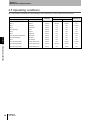
4.5 Operating conditions
60
Section 5 Setup Mode
61
5.1 Accessing setup mode
62
5.2 How to set up parameters
63
Section 6 Reference
67
6.1 Processing Time (information only)
68
6.2 Performance Data Based on Operating Conditions (information only)
69
6.2.1 Effect of nearby metal object onto IDRW head
69
6.2.2 Spacing for installing IDRW heads
70
6.2.3 Effect of inclination of ID tag
71
Section 7 Troubleshooting
73
7.1 No acknowledge message (Acknowledge message not yet received)
74
7.2 Acknowledge message received (other than SSACK="NO")
75
Revision History
6
37
V700-L21
User's Manual
77
Section 1
Section 1
System Configuration and Features
8
1.2 Features
9
V700-L21
User's Manual
System Configuration and Features
1.1 System configuration
7
Section 1
System Configuration and Features
1.1 System configuration
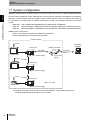
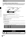
OMRON's CIDRW (Carrier ID Reader/Writer) is an RFID system that conforms to SECSs (SEMI Equipment
Section 1
Communications Standards, where SEMI stands for Semiconductor Equipment and Materials International),
1.1 System configuration
include:
and which comprises Model V700-L21 CIDRW controller, Model V700-L11 ID link unit, Model V700-HMD13
or V700-HMD11-1 ID R/W head, and Model V700-D23P41 ID tag. The normative SECSs for the system
• SEMI E99
THE CARRIER ID READER/WRITER FUNCTIONAL STANDARD
• SEMI E5
SEMI EQUIPMNT COMMUNICATIONS STANDARD 2 MESSAGE CONNECT (SECS II)
• SEMI E4
SEMI EQUIPMENT COMMUNICATIONS STANDARD 1 MESSAGE TRANSFER (SECS I)
CIDRW system configuration
* SEMI: Semiconductor Equipment and Materials International
* SECS: SEMI Equipment Communications Standard
CIDRW system
ID tag
CIDRW controller
ID link unit
RS-232C
SECS I / II
RS-232C
IDRW head
24 V power supply
ID tag
Upstream
controller
24 V power
supply
RS-485
ID link unit
IDRW head
24 V power supply
ID tag
RS-485
ID link unit
(Max. 31 units)
IDRW head
24 V power supply
For detailed information about the above-mentioned standards, contact SEMI addressed at:
805 East Middlefield Road, Mountain View, CA 94043
8
V700-L21
User's Manual
Section 1
System Configuration and Features
1.2 Features
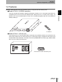
OMRON's SEMI standard-conforming CIDRW system is configured with the following units:
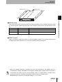
This unit is linked with upstream equipment (upstream controller, etc.) in accordance with SECS I/IIcompatible protocol and controls the CIDRW system. Being driven by a 24 VDC power supply, it is
reliably installing it.
1.2 Features
linked to one or more ID R/W heads via a link unit. It is delivered together with four lock washers for
Section 1
● Model V700-L21 (CIDRW controller)
4 washers
● Model V700-L11 (ID link unit)
This unit allows one or more ID R/W heads to be linked to the CIDRW controller unit, and will be hereunder simply called "link unit". Being driven by a 24 VDC power supply, it supplies 5 VDC power to the
ID R/W heads. When delivered, it includes connectors (COMBICON screw-down plug: Model XW4B05C1-H1-D) for multi-connection ports.
RUN COMM
ID ERR
Connector for multi-connection port
V700-L21
User's Manual
9
Section 1
System Configuration and Features
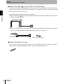
● Model V700-HMD13 , or V700-HMD11-1 (ID R/W head)
An ID R/W head reads or writes data from or into the memory on ID tag without a need to contact the
ID tag. It will be hereunder simply called IDRW head (or, more simply, IDRWH). It is operated as linked
Section 1
to the CIDRW controller via a link unit.
Two differently formed IDRW head types are available:
1.2 Features
➀ Model V700-HMD13
features a form and data transaction performance suitable for the "undocked
position" per SEMI standards.
➁ Model V700-HMD11-1 features a form and data transaction performance suitable for the "docked
position" per SEMI standards. It is delivered together with two mounting nuts.
Mounting nut (2
M4)
● Model V700-D23P41 (ID tag)
This is a round rod type ID tag that measures 3.9 mm in diameter and 25 mm in length. It contains a
memory space of 240 bytes that allows a user to read or write data from or into it.
10
V700-L21
User's Manual
Section 2
Unit Specifications
Section 2
12
2.1.1 Names and functions of various
components/specifications
12
2.1.2 Interface specifications
15
2.1.3 Dimensional drawing and mounting method
17
2.2 Link unit: Model V700-L11
18
2.2.1 Names and functions of various
components/specifications
18
2.2.2 Interface specifications
21
2.2.3 Dimensional drawing and mounting method
24
2.3 IDR/W head: Model V700-HMD13
2.3.1 Names and functions of various
components/specifications
25
25
2.3.2 Interface specifications (same as
with Model V700-HMD11-1)
26
2.3.3 Dimensional drawing and mounting method
27
2.3.4 Communication performance (information only)
29
2.4 IDR/W head: Model V700-HMD11-1
2.4.1 Names and functions of various
components/specifications
30
30
2.4.2 Interface specifications (same as
with Model V700-HMD13 )
31
2.4.3 Dimensional drawing and mounting method
32
2.4.4 Communication performance (information only)
33
2.5 ID tag: Model V700-D23P41
Unit Specifications
2.1 CIDRW controller: Model V700-L21
34
2.5.1 Dimensional drawing and specifications
34
2.5.2 Memory map
35
V700-L21
User's Manual
11
Section 2
Unit Specifications
2.1 CIDRW controller: Model V700-L21
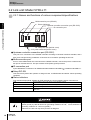
2.1.1 Names and functions of various components/specifications
Section 2
POWER indicator
STATUS indicators
POWER
STATUS
ID port
Mounting hole
4
2.1 CIDRW controller: Model V700-L21
OPERATING
ALARMS
BUSY
ERROR
SECS port
SECS
ID
Maintenance port
(w/ cover)
24 V power supply terminal (with cover)
● 24 V power supply terminal (with cover)
A power terminal and a GR (frame ground) terminal, for supplying 24 VDC.
● SECS port
A port for connection to upstream equipment (equipment controller, etc.). Conforms to SECS I/II.
● ID port
A port for connection to a link unit that further connects to an IDRW head.
● Maintenance port (w/ cover)
Not used. Do not remove the cover.
● POWER indicator
An LED lamp that indicates whether or not the CIDRW controller is powered. It remains lit green when
the controller is powered.
● STATUS indicators
Four indicator lamps (OPERATING, ALARMS, BUSY, ERROR) indicate the current operating status of
the CIDRW controller.
All of these LEDs either remain stably lit or flash immediately after the CIDRW controller is powered
ON or during the initial stage of resetting of the controller.
OPERATING
Green
Lights when the state model of CIDRW is OPERATING.
ALARMS
Green
Lights when "Alarm Status" on the CIDRW is "1" (ALARMS).
BUSY
Green
Lights when "Operational Status" on the CIDRW is "BUSY".
ERROR
Red
Lights for 50 ms when a fault is detected (SSACK is not "NO") during service.
Be sure to ground the GR (frame ground) by class D earth work (grounding resistance of
100 Ω or less, diameter of grounding conductor of 1.6 mm or greater).
Otherwise, the CIDRW controller may fail to perform as designed.
12
V700-L21
User's Manual
Section 2
Unit Specifications
MODE switch
RESET switch
MODE
RESET
Section 2
SECS
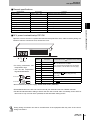
● MODE switch
This is a 8-position rotary switch that selects an intended operation mode. Available operation modes
are normal operation mode and setup mode. The controller is factory-set to normal operation mode
(0).
MODE SW position
Operation mode
Function
0
Normal operation mode
The controller serves as a CIDRW.
3
Setup mode
The operator can set up parameters.*
1, 2, 4, 5, 6, 7
Do not select these positions. Reserved
* For the information about parameters, refer to Sec. 5.2 "How to set parameters".
● RESET switch
2.1 CIDRW controller: Model V700-L21
ID
Using a pointed tool, depress this switch to reset the CIDRW controller. The controller will be reset to
the original state that is same as a one occurring immediately after powering ON.
• When the CIDRW controller is powered ON, the mode specified by the MODE switch is
automatically accessed. Remember that changing the MODE switch setting while the controller is
running does not switch over the current operation mode. To enable another operation mode,
power OFF and power ON again the CIDRW controller or press the RESET switch.
• NEVER attempt to select any of the illegal settings 1, 2, 4, 5, 6 and 7.
V700-L21
User's Manual
13
Section 2
Unit Specifications
■ General specifications
Characteristic
Supply voltage
Specification
24 VDC, +10%, −15%
Comment
Supplied from the power terminals
Section 2
2.1 CIDRW controller: Model V700-L21
Current consumption
150 mA max.
Approx. 10 A max. with rush current
Dimensions
150 × 167 × 28 mm
Except for protrusions on connectors
Protection class
IP20 (per IEC 60529)
Operating ambient
temperature
0 to +40°C
No freezing
Operating ambient
humidity
10 to 85%RH
No dew condensation
Storage ambient
temperature
-15 to +65°C
No freezing
Storage ambient
humidity
10 to 95%RH
No dew condensation
Mounting system
Secured with four M4 screws.
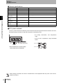
Use the enclosed washers.
■ 24 V power terminals
The 24 V power terminals include the power terminals and frame ground terminal. Remove the cover,
and make wiring connections. After the wiring work, reinstall the cover.
• For wiring connections, use compression
rings.
• Use the M3 compression rings illustrated
below.
GR (frame ground)
6 mm max.
24 VDC
• Recommended 24 V power supply:
6 mm max.
Model S82K-03024 (OMRON)
Wrong wiring connection can lead to a malfunction of the equipment. Be fully sure of the correct
wiring connections.
14
V700-L21
User's Manual
Section 2
Unit Specifications
2.1.2 Interface specifications
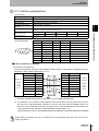
(1) SECS port
Characteristic
Specification
Connector specification
9-pin D-SUB male connector with #4-40UNC lock screws
RS-232C
Synchronization
Asynchronous, start-stop synchronization
Communications control
standard
SEMI E4 SECS I, E5 SECS II
Baud rate
1200, 2400, 4800, 9600, 19200, 38400, 57600, 115200 bps
(9600 bps is default; selectable in setup mode)
Total cable length
Start bit
Data bit
Parity bit
Stop bit
Total
1
8
None
1
10
15 m max.
(Pin arrangement)
Pin No.
Signal name
Symbol
1
1
5
6
9
Direction
<N.C.>
Unused
2
Receive data
RD
Input
3
Send data
SD
Output
4
−
5
Signal ground
6
−
7
8
−
Output
SG
−
−
Input
Request send
RS
Output
Clear to send
(CS)
Input
9
Comment
<N.C.>
Normally OFF
Leave this pin OPEN.
Normally OPEN during service
Not functioning
Unused
2.1 CIDRW controller: Model V700-L21
Character format
(E4 SECS I, fixed)
Section 2
Communication standard
■ Cable connection example
<Connection with DOS/V PC>
Connect the upstream controller to the CIDRW controller using the cable whose configuration is specified below. Limit the whole cable length to 15 m.
Symbol
DOS/V PC
D-SUB
9-pin
socket
#4-40
Pin No.
Pin No.
Symbol
1
1
RD
2
2
RD
SD
3
3
SD
4
4
5
5
SG
6
RS
7
CS
8
SG
6
*2-1
9
*2
*2-2
7
RS
8
CS
CIDRW
controller
D-SUB
9-pin
socket
#4-40
9
*1
*1 Ground the shielded cable either on the PC/AT side or CIDRW controller side.
*2 The controller can run without a wiring between RS and CS. Note, however, that a wiring connection from RS to CS(*2-2)enables verification of correct connection with the CIDRW system. Furthermore, with an additional connection from RS to CS(*2-1),the directionality of cable will be lost.
• Recommended cable: CO-MA-VV-SB 5PX28AWG (Hitachi Cable, Ltd.)
• Recommended connector: socket-Model XM2D-0901 (OMRON), hood-Model XM2S-0913 (OMRON)
Wrong wiring connection can lead to a malfunction of the equipment. Be fully sure of the correct
wiring connections.
V700-L21
User's Manual
15
Section 2
Unit Specifications
(2) ID port
Characteristic
Specification
Connector specification
9-pin D-SUB connector plug with #4-40UNC lock screws
Communication standard
RS-232C
Baud rate
9600, 19200, 38400 bps
(9600 bps is default; selectable in setup mode)
Total cable length
15 m max.
Section 2
(Pin arrangement)
2.1 CIDRW controller: Model V700-L21
1
Pin No.
Symbol
Direction
−
Input
Receive data
RD
Input
3
Send data
SD
Output
4
−
−
Output
5
Signal ground
SG
−
6
−
−
Input
7
Request send
RS
Output
8
Clear to send
CS
Input
For verifying established link
9
−
−
Input
Leave this pin OPEN.
−
2
5
6
9
Signal name
1
Comment
Leave this pin OPEN.
Normally OFF
Leave this pin OPEN.
● Connection with link unit
Connect the CIDRW controller to the link unit using the cable whose configuration is specified below.
Limit the whole cable length to 15 m.
Symbol
CIDRW
controller
D-SUB
9-pin
socket
#4-40
Pin No.
Pin No.
1
1
RD
2
2
RD
SD
3
3
SD
4
4
5
5
6
6
RS
7
7
RS
CS
8
8
CS
9
9
SG
Symbol
SG
Link unit
D-SUB
9-pin
socket
#4-40
*1
*1 Ground the shielded cable either on the CIDRW controller side or link unit side.
• Recommended cable: CO-MA-VV-SB 5PX28AWG (Hitachi Cable, Ltd.)
• Recommended connector: socket-Model XM2D-0901 (OMRON), hood-Model XM2S-0913
(OMRON)
Wrong wiring connection can lead to a malfunction of the equipment. Be fully sure of the correct
wiring connections.
16
V700-L21
User's Manual
Section 2
Unit Specifications
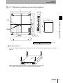
2.1.3 Dimensional drawing and mounting method
150
28
130
Section 2
Mounting holes (1: 2)
130
0.2
2.1 CIDRW controller: Model V700-L21
POWER
indicator
167
151
0.2
3
151
4-M4
24
STATUS
indicators
7
P6 3
30
4- 4.5
(mounting holes)
Case material Steel sheet (SPCC-P)
(Unit: mm)
● Mounting method
Install the controller using the four mounting holes and four M4 screws together with the enclosed
washers.
* Be sure to limit the tightening torque for the M4 screws to 1.2 N-m or less.
* Do not apply an organic solvent such as thread glue to the threads.
V700-L21
User's Manual
17
Section 2
Unit Specifications
2.2 Link unit: Model V700-L11
2.2.1 Names and functions of various components/specifications
Section 2
Multiconnection port (RS-485)
Status indicators
Upstream controller connection port (RS-232C)
ID connection port
2.2 Link unit: Model V700-L11
RUN COM
ID ERR
Setup DIP-SW (behind cover)
24 V power terminals (behind cover)
● Upstream controller connection port (RS-232C)
This port is for connection to the CIDRW controller according to RS-232C interface standard, and a
dust cover has been factory-installed to it. Remove the cover before operating the link unit.
● Multiconnection port
If two or more IDRW heads are connected to the CIDRW controller, connect this port to a multiconnection port on another link unit. This port contains a GR (frame ground) terminal.
● ID connection port
A port dedicated to connection of an IDRW head-either Model V700-HMD13
or Model V700-HMD11-1.
● Setup DIP-SW
This switch array allows the operator to assign ID Nos. to IDRW heads and define various operating
conditions.
● Status indicators
Four indicator lamps (RUN, COMM, ID, ERR) indicate the current operating status of the link unit.
RUN
Remains stably lit as long as the link unit is operating normally.
COMM
Remains lit during data transaction with an upstream controller.
ID
Remains lit during data transaction with an IDRW head.
ERR
Lights when a fault is detected during data transaction with an upstream controller or
IDRW head.
Regardless of whether or not the multiconnection port is used, be sure to ground the GR
(frame ground) by class D earth work (grounding resistance of 100 Ω or less, diameter of
grounding conductor of 1.6 mm or greater).
Otherwise, the link unit may fail to perform as designed.
18
V700-L21
User's Manual
Section 2
Unit Specifications
■ General specifications
Characteristic
Specification
Comment
Supplied from the power terminals
250 mA max.
Approx. 10 A max. with rush current
Dimensions
110 × 65 × 64 mm
Except for mounting hook
Protection class
IP20 (per IEC 60529)
Operating ambient temperature
0 to +40°C
No freezing
Operating ambient humidity
35 to 85%RH
No dew condensation
Storage ambient temperature
−15 to +50°C
No freezing
Storage ambient humidity
35 to 85%RH
No dew condensation
Mounting system
Secured with two M4 screws
■ 24 V power terminals/setup DIP-SW
Open the cover to access 24 V power terminals and setup DIP-SW. Then, make necessary wiring connections. After the connection work, reclose the cover.
ON
1
2
3
4
5
6
SW No.
24 VDC
• For wiring connections, use
compression rings.
• Use the M3 compression
rings illustrated below.
6 mm max.
6 mm max.
7
8
9
2.2 Link unit: Model V700-L11
24 VDC, +10%, −15%
Current consumption
Section 2
Supply voltage
10
Description
Meaning
(Content within a box represents factory-setting)
1
Node No. 1
01 to 31
No. 1 is LSB, and No. 5 is MSB.
(For correspondence between DIP-SW settings
and node Nos., see the table in the next page.)
2
Node No. 2
3
Node No. 3
4
Node No. 4
5
Node No. 5
6
Baud rate setting 1
7
Baud rate setting 2
38400/19200/ 9600 /4800bps
[ON,ON] [ON,OFF] [OFF,OFF] [OFF,ON]
:[No7,No6]
8
Reserved
Always leave in OFF position.
9
Reserved
ReservedAlways leave in OFF position.
10
RS-485 terminator
ON/ OFF
• Recommended 24 V power supply: Model S82K-03024 (OMRON)
• Set the Baud rate on the link unit to that on the ID port of Model V700-L21 CIDRW controller.
• Set the RS-485 terminator setting to ON for the link units on both ends of multidrop, and to OFF for
other units. If only one link unit is operated, set the terminator setting to OFF.
Wrong wiring connection can lead to a malfunction of the equipment. Be fully sure of the correct
wiring connections.
V700-L21
User's Manual
19
Section 2
Unit Specifications
• Assign a unique node No. to an IDRW head within a given subsystem. A node No. defined with this
DIP-SW is taken as a "Head ID" (E99).
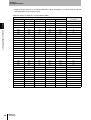
[DIP-SW setting vs. Node No. correspondence table]
Switch No. in setup DIP-SW
Section 2
2.2 Link unit: Model V700-L11
20
V700-L21
User's Manual
1
2
3
4
5
Node No.
(= "Head ID")
OFF
OFF
OFF
OFF
OFF
01
ON
OFF
OFF
OFF
OFF
02
OFF
ON
OFF
OFF
OFF
03
ON
ON
OFF
OFF
OFF
04
OFF
OFF
ON
OFF
OFF
05
ON
OFF
ON
OFF
OFF
06
OFF
ON
ON
OFF
OFF
07
ON
ON
ON
OFF
OFF
08
OFF
OFF
OFF
ON
OFF
09
ON
OFF
OFF
ON
OFF
10
OFF
ON
OFF
ON
OFF
11
ON
ON
OFF
ON
OFF
12
OFF
OFF
ON
ON
OFF
13
ON
OFF
ON
ON
OFF
14
OFF
ON
ON
ON
OFF
15
ON
ON
ON
ON
OFF
16
OFF
OFF
OFF
OFF
ON
17
ON
OFF
OFF
OFF
ON
18
OFF
ON
OFF
OFF
ON
19
ON
ON
OFF
OFF
ON
20
OFF
OFF
ON
OFF
ON
21
ON
OFF
ON
OFF
ON
22
OFF
ON
ON
OFF
ON
23
ON
ON
ON
OFF
ON
24
OFF
OFF
OFF
ON
ON
25
ON
OFF
OFF
ON
ON
26
OFF
ON
OFF
ON
ON
27
ON
ON
OFF
ON
ON
28
OFF
OFF
ON
ON
ON
29
ON
OFF
ON
ON
ON
30
OFF
ON
ON
ON
ON
31
ON
ON
ON
ON
ON
Prohibited
Section 2
Unit Specifications
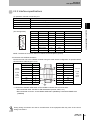
2.2.2 Interface specifications
(1) Upstream controller connection port
Characteristic
Specification
9-pin D-SUB connector plug, with #4-40UNC lock screws
Communication standard
RS-232C
Baud rate
38400, 19200, 9600, 4800 bps (selectable with DIP-SW)
Total cable length
15 m max.
Pin No.
Signal name
Symbol
Direction
Comment
1
9
2
Receive data
RD
Input
3
Send data
SD
Output
4
−
−
−
5
Signal ground
SG
−
7
Request send
RS
Output
8
Clear to send
CS
Input
9
−
−
−
6
1
Normally OPEN during service
2.2 Link unit: Model V700-L11
(Pin arrangement)
Section 2
Connector specification
NOTE: The base of connector does not continue to the GR (frame ground).
<Connection with CIDRW controller>
Connect the link unit to the CIDRW controller using the cable whose configuration is specified below.
Limit the whole cable length to 15 m.
Symbol
CIDRW
controller
D-SUB
9-pin
socket
#4-40
Pin No.
Pin No.
1
1
RD
2
2
RD
SD
3
3
SD
4
4
5
5
6
6
RS
7
7
RS
CS
8
8
CS
9
9
SG
*1
Symbol
SG
Link unit
D-SUB
9-pin
socket
#4-40
*1 Ground the shielded cable either on the CIDRW controller side or link unit side.
• Recommended cable: CO-MA-VV-SB 5PX28AWG (Hitachi Cable, Ltd.)
• Recommended connector: socket-Model XM2D-0901 (OMRON), hood-Model XM2S-0913
(OMRON)
Wrong wiring connection can lead to a malfunction of the equipment. Be fully sure of the correct
wiring connections.
V700-L21
User's Manual
21
Section 2
Unit Specifications
(2) Multiconnection port
Characteristic
Specification
Connector specification
5-pin special connector (built into the link unit)
Communication standard
RS-485
Baud rate
38400, 19200, 9600, 4800 bps (selectable with DIP-SW)
Total cable length
50 m max.
Section 2
(Pin arrangement)
Pin No.
Name
5
−
Internally connected to pin 2.
4
+
Internally connected to pin 1.
3
GR
2
−
Internally connected to pin 5.
1
+
Internally connected to pin 4.
2.2 Link unit: Model V700-L11
5
Comment
Frame ground
1
• Recommended cable
RS-485 signal line: Tatei Densen MVVS 2CX0.5SQ
Frame ground line: Cable rated at AWG 22 to 20
• Recommended compression ring
Phoenix Contact AI0.5-8WH
Compression ring
Cable
Insert the cable and crimp.
* The following product is recommended as a compression ring for connecting two cables to one
terminal.
Phoenix Contact AI-TWIN2×0.5-8WH
Use the product below as a crimping tool for crimping the compression ring.
Phoenix Contact CRIMPFOX UD6
22
V700-L21
User's Manual
Section 2
Unit Specifications
■ How to connect cables
➀ Fit a compression ring to the stripped section of each cable.
Next, being sure of the connector orientation, insert each cable into a corresponding hole on the
connector.
Section 2
An ordinary screwdriver whose shank is tapered at the tip does not go all the way into the hole. Use
a miniature flat-blade screwdriver with a straight shank.
Tighten the cable locking screws at an appropriated tightening torque (approx. 0.5 N-m).
The following purpose-built screwdriver is available:
OMRON: Model XW4Z-00C
Form of tip
Side view Front view
Miniature flat-blade screw
driver with straight shank
0.6 mm
2.2 Link unit: Model V700-L11
➁ Securely fasten each cable using the cable locking screw on the connector.
3.5 mm
➂ Connect the connector to the link unit together with the cables.
Match the orientation of link unit side connector with that of cable side connector, insert the cable
side connector all the way, and then tighten the connector lock screws.
Lock screws
➃ When removing the connector, fully loosen the two lock screws and draw out it straight by holding
the protrusions on connector. If the connector does not easily come loose, draw it out while holding
down the link unit proper.
V700-L21
User's Manual
23
Section 2
Unit Specifications
2.2.3 Dimensional drawing and mounting method
110
RS-232C connector
41.3
41.5
Section 2
20.3
ID port connector
2.2 Link unit: Model V700-L11
35.2
65
2-
4
4.5
4 Status indicators
RS-485 connector
4
60
Mounting holes
55
100
2-M4 OR
4.2
Case material PC/ABS resin
(Unit: mm)
* Be sure to limit the tightening torque for the M4 screws to 1.2 N-m or less.
Do not apply an organic solvent such as thread glue to the threads. Otherwise, cracking can occur
on the case.
24
V700-L21
User's Manual
Section 2
Unit Specifications
2.3 IDR/W head: Model V700-HMD13
2.3.1 Names and functions of various components/specifications
Section 2
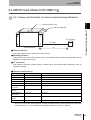
Communication area
Mounting bracket
I/F cable
Antenna section
1m
● Antenna section
This section reads or writes data from or into an ID tag.
2.3 IDR/W head: Model V700-HMD13
I/F connector
● Mounting bracket
This bracket is for securing the antenna section. The vertical position of the mounting bracket can be
adjusted in a range of 0 to 45 mm.
● I/F connector
This interface connector supplies power to IDR/W head, and permits data transmission with an
upstream controller.
■ General specifications
Characteristic
Specification
Comment
Supply voltage
5 VDC±5%
Supplied from the I/F connector
Current consumption
400 mA max.
When 5 VDC is input: approx. 8 A with rush current
Dimensions
44.8 × 149.8 × 73 mm
Except for cable
Cable length
1 m (dia. 6 mm)
Can be extended to 4 m in conjunction with Model V700-L11
Protection class
IP30 (per IEC 60529)
Operating ambient
temperature
0 to +40°C
No freezing
Operating ambient
humidity
35 to 85%RH
No dew condensation
Storage ambient
temperature
−15 to +50°C
No freezing
Storage ambient
humidity
35 to 85%RH
No dew condensation
Mounting system
Screwed down at four points.
Capable of mounting to sheet metal*
* Be sure to ground the sheet metal that accepts the IDR/W head by class D earth work (grounding
resistance of 100 Ω or less, diameter of grounding conductor of 1.6 mm or greater).
V700-L21
User's Manual
25
Section 2
Unit Specifications
2.3.2 Interface specifications (same as with Model V700-HMD11-1)
Characteristic
Specification
Section 2
Connector specification
9-pin D-SUB connector plug, with M2.6 lock screws
Communication standard
RS-232C
(Pin arrangement)
Pin No.
Signal name
Symbol
Direction
Comment
2.3 IDR/W head: Model V700-HMD13
1
1
9
2
Send data
SD
Input
3
Receive data
RD
Output
4
Request send
RS
Input
5
Clear to send
CS
Output
6
+5 V input
5V
Input
5 VDC±5%
7
0 V input
0V
Input
Internally connected to SG
Signal ground
SG
−
Internally connected to 0V
Normally ON
8
9
<Connection with link unit>
The IDR/W head can be directly connected to the ID connection port on the link unit. When considering
extending the cable, use the cable whose configuration is specified below. Limit the whole cable length
to 4 m.
Symbol
Link unit
D-SUB
9-pin
plug
M2.6
Pin No.
Pin No.
1
1
Symbol
SD
2
2
SD
RD
3
3
RD
RS
4
4
RS
CS
5
5
CS
5V
6
6
5V
7
0V
0V
SG
7
*
8
8
9
9
IDRWH
D-SUB
9-pin
socket
M2.6
nut
SG
* For the 5 V/0 V power line, use a cable whose conductor size is AWG22 or greater.
• Recommended cable:OTSC-8PVB-2 No. 22AWG (Onamba)
• Recommended connector: <IDRWH side> socket-Model XM2D-0901 (OMRON),
hood-Model XM2S-0911 (OMRON),
lock-Model XM2Z-0001 (OMRON)
<Link unit side> plug-Model XM2A-0901 (OMRON),
hood-Model XM2S-0911(OMRON)
Wrong wiring connection can lead to a malfunction of the equipment. Be fully sure of the correct
wiring connections.
26
V700-L21
User's Manual
Section 2
Unit Specifications
2.3.3 Dimensional drawing and mounting method
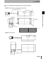
● IDR/W head with mounting brackets installed
PVC-insulated round cable 6 (7/
8-core, standard length, 1 m
0.18)
Coil
4-M4
(FOUP side)
32
44.8
17.0
Section 2
149.8
Mounting bracket
(material: SUS 304)
73
45
57
Mounting bracket
(material: SUS 304)
4-M4
8.4
422.4
4.5
11.5 cable lead-in hole
2.3 IDR/W head: Model V700-HMD13
119.8
44
36.4
Case sideplate
Aluminum plate (A5052P)
Communication area on case
Bakelite
Mounting bracket
SUS 304 (t=1.0)
Cable
PVC cable
(Unit: mm)
● IDR/W head proper
44.8
17.0
Coil
119.8
73
57
44.8
4-M4
8.4
119.8
22.4
11.5 cable lead-in hole
36.4
V700-L21
User's Manual
27
Section 2
Unit Specifications
15
15
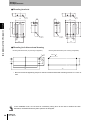
● Mounting brackets
2-M4
2-M4
10.1
2.3 IDR/W head: Model V700-HMD13
4.1
2-
2-
4.5
69
45
35
57
15
4
35
45
69
57
15
Section 2
13
4.1
44.8
4
10.1
44.8
4.5
4.1
4.1
8.4
8.4
36.4
36.4
● Mounting hole dimensional drawing
4.2
4-M4 OR
4.2
35
4-
45
Mounting holes dimensions (front mounting configuration)
25
Mounting holes dimensions (top mounting configuration)
120
140
140
* Be sure to limit the tightening torque for the M4 screws and bracket mounting screws to 1.2 N-m or
less.
In the installation work, do not exert an excessively strong force to the case or deform the case.
Otherwise, the IDR/W head may fail to perform as designed.
28
V700-L21
User's Manual
Section 2
Unit Specifications
2.3.4 Communication performance (information only)
Communication area (Model V700-HMD13
vs. Mode V700-D23P41)
80
Section 2
Locus of the tip of
V700-D23P41
70
2.3 IDR/W head: Model V700-HMD13
60
V700-D23P41
50
FOUP side
40
30
20
10
0
Antenna
10
20
30
40
50
60
70
Unit: mm
Location of the tip of ID tag
ID tag mounting position stipulated
by SEMI
Case (sideplate)
V700-L21
User's Manual
29
Section 2
Unit Specifications
2.4 IDR/W head: Model V700-HMD11-1
2.4.1 Names and functions of various components/specifications
Section 2
Communication area
I/F connector
2.4 IDR/W head: Model V700-HMD11-1
I/F cable
1m
Antenna section
Status indicators (located on sideplate)
● Antenna section
This section reads or writes data from or into an ID tag.
● I/F connector
This interface connector supplies power to IDR/W head, and permits data transmission with an
upstream controller.
● Status indicators
Green
Red
Remains lit during data transaction with an ID tag.
Lights if data transaction with an ID tag has failed to complete normally.
■ General specifications
Characteristic
Specification
Comment
Supply voltage
5 VDC±5%
Supplied from the I/F connector
Current consumption
250 mA max.
When 5 VDC is input: approx. 4 A with rush current
Dimensions
40 × 53 × 23 mm
Except for cable
Cable length
1 m (dia. 6 mm)
Can be extended to 4 m in conjunction with Model V700-L11
Protection class
IP67 (per IEC 60529)
IP67G (per JEM 1030)
The connector is not resistant to water or oil.
Operating ambient temperature
−10 to +55°C
No freezing
Operating ambient humidity
25 to 85%RH
No dew condensation
Storage ambient temperature
−25 to +65°C
No freezing
Storage ambient humidity
25 to 95%RH
No dew condensation
Mounting system
Screwed down at two points
with M4.
Capable of mounting to sheet metal*
* Be sure to ground the sheet metal that accepts the IDR/W head by class D earth work (grounding
resistance of 100 Ω or less, diameter of grounding conductor of 1.6 mm or greater).
30
V700-L21
User's Manual
Section 2
Unit Specifications
2.4.2 Interface specifications (same as with Model V700-HMD13 )
Characteristic
Specification
9-pin D-SUB connector plug, with M2.6 lock screws
Communication standard
RS-232C
(Pin arrangement)
Pin No.
Signal name
Symbol
Direction
Comment
1
9
2
Send data
SD
Input
3
Receive data
RD
Output
4
Request send
RS
Input
5
Clear to send
CS
Output
6
+5 V input
5V
Input
5 VDC±5%
7
0 V input
0V
Input
Internally connected to SG
Signal ground
SG
−
Internally connected to 0V
Normally ON
8
9
<Connection with link unit>
The IDR/W head can be directly connected to the ID connection port on the link unit. When considering
2.4 IDR/W head: Model V700-HMD11-1
1
Section 2
Connector specification
extending the cable, use the cable whose configuration is specified below. Limit the whole cable length
to 4 m.
Symbol
Link unit
D-SUB
9-pin
plug
M2.6
Pin No.
Pin No.
1
1
SD
2
2
SD
RD
3
3
RD
RS
4
4
RS
CS
5
5
CS
5V
6
6
5V
0V
7
7
0V
SG
*
8
8
9
9
Symbol
IDRWH
D-SUB
9-pin
socket
M2.6
nut
SG
* For the 5 V/0 V power line, use a cable whose conductor size is AWG22 or greater.
• Recommended cable:OTSC-8PVB-2 No. 22AWG (Onamba)
• Recommended connector: <IDRWH side> socket-Model XM2D-0901 (OMRON),
hood-Model XM2S-0911 (OMRON),
lock-Model XM2Z-0001 (OMRON)
<Link unit side> plug-Model XM2A-0901 (OMRON),
hood-Model XM2S-0911(OMRON)
Wrong wiring connection can lead to a malfunction of the equipment. Be fully sure of the correct
wiring connections.
V700-L21
User's Manual
31
Section 2
Unit Specifications
2.4.3 Dimensional drawing and mounting method
Model V700-HMD11-1
2- 4.5
(mounting hole)
10
6, length 1000
Lock screw
32
0.1
28
40
5
2-
10
Section 2
4-R1
2.4 IDR/W head: Model V700-HMD11-1
5
27
45.5
6
5
13
18
Status indicator
20
11
15
23
53
Case material ABS resin
(Unit: mm)
Filler resin
Epoxy resin
Cable
PVC (oil-resistant)
■ Mounting method
(1) Front mounting
2-M4
Center of coil
28 0.2 40
27
53
(2) Back mounting
Insert the enclosed nuts into areas A, and mount the head.
Center of coil
Nut
2-
4.5
A
28
0.2
27
* Be sure to limit the tightening torque for the M4 screws to 1.2 N-m or less.
Do not apply an organic solvent such as thread glue to the threads. Otherwise, cracking can
occur on the case.
32
V700-L21
User's Manual
Section 2
Unit Specifications
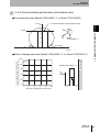
2.4.4 Communication performance (information only)
● Communication area (Model V700-HMD11-1 vs. Mode V700-D23P41)
Y
Recommended communication area
Section 2
Y (mm)
50
40
37mm
Tag
20
Model
V700-HMD11-1
10
-50
-40
-30
-20
-10
0
10
20
30
40
X
50
X (mm)
100
80
Model V700-HMD11-1
60
Metal body
Communication distance (data without
background metal is taken as 100%) Y (%)
● Effect of background metal (Model V700-HMD11-1 vs. Mode V700-D23P41)
2.4 IDR/W head: Model V700-HMD11-1
30
Tag
40
20
0
0
20
40
60
80
100
Distance to background metal X (mm)
Y
X
V700-L21
User's Manual
33
Section 2
Unit Specifications
2.5 ID tag: Model V700-D23P41
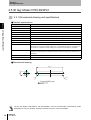
2.5.1 Dimensional drawing and specifications
Section 2
■ General specifications
Characteristic
Specification
Memory capacity
240 bytes (user area)
Memory type
EEP-ROM
2.5 ID tag: Model V700-D23P41
Data retention time
10 years after data writing
Number of overwrites
100,000 times per address
Operating ambient temperature
−25 to +70°C (no freezing)
Operating ambient temperature
−40 to +110°C(no freezing)
Storage ambient temperature
−40 to +110°C (no freezing)
Operating ambient humidity
35 to 95%RH (no dew condensation)
Protection rating( IEC 60529)
IP67
Vibration resitance
Endurance 10 to 2000 Hz, single amplitude 0.75 mm
Acceleration of 150 m/s2 is applied in each of X, Y and Z directions each for 15 minutes, and
this sequence is repeated 10 times, thereby the ID tag must not develop any irregularity.
Shock resistance
An impact, that is, acceleration of 500 m/s2, is applied three times in each of X, Y and Z
directions, and this sequence is repeated 18 times, thereby the ID tag must not develop any
irregularity.
Materials
Case: PBT resin, filler: epoxy resin
Mass
Approx. 1 g
■ Dimensional drawing
0.1
3.9
0.1
25
R1
R0.25
Toward IDRW head
The ID tag Model V700-D32P41 has directionality, and its communication performance varies
depending on how it is oriented. Therefore, be sure to use it in correct orientation.
34
V700-L21
User's Manual
Section 2
Unit Specifications
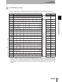
2.5.2 Memory map
The carrier IDs and data segments are assigned to the following memory addresses in an ID tag.
Page
8 bytes/page
DATASEG LENGTH
01h
02h
03h
04h
05h
06h
07h
2
08h
09h
0Ah
0Bh
0Ch
0Dh
0Eh
0Fh
3
10h
11h
12h
13h
14h
15h
16h
17h
"S01"
8
4
18h
19h
1Ah
1Bh
1Ch
1Dh
1Eh
1Fh
"S02"
8
5
20h
21h
27h
"S03"
8
6
28h
29h
2Fh
"S04"
8
7
30h
31h
37h
"S05"
8
8
"S06"
8
9
"S07"
8
"S08"
8
"S09"
8
"S10"
8
"S11"
8
"S12"
8
"S13"
8
"S14"
8
11
12
13
14
68h
69h
6Fh
15
70h
71h
77h
16
78h
79h
7Fh
Data area (total 224 bytes)
10
Carrier ID
(16 byte)
16
2.5 ID tag: Model V700-D23P41
00h
Section 2
1
8
*
8
27
D0h
D1h
D8h
"S25"
8
28
D8h
D9h
DFh
"S26"
8
29
E0h
E1h
E7h
"S27"
8
30
E8h
E9h
EFh
"S28"
8
EAh
EBh
ECh
EDh
EEh
* When the Model V700-HMD13 is used in the CIDWR system, the data segments assigned to pages
13 through 30 have operational limitations. For further information, refer to "Limitations about Model
V700-HMD13" in the earlier part of this manual. The Model V700-HMD13A does not have such limitations.
V700-L21
User's Manual
35
Section 2
Unit Specifications
MEMO
Section 2
2.5 ID tag: Model V700-D23P41
36
V700-L21
User's Manual
Section3
System Connections
38
3.2 System configuration example
39
Section 3
3.1 Connection work and startup
System Connections
V700-L21
User's Manual
37
Section 3
System Connections
3.1 Connection work and startup
➀ Connect the CIDRW controller to an upstream controller (equipment controller, etc.) with an RS232C cable. The maximum allowable cable length is limited to 15 m. According to the intended
CIDRW system configuration, choose the protocol parameters for the CIDRW controller and Baud
rate for communications with the link unit. Parameter setting can be achieved in setup mode.
➁ Connect the CIDRW controller to the link unit with an RS-232C cable. The maximum allowable
cable length is limited to 15 m. Determine the DIP-SW setting so that the Baud rate for the link unit
is same as that for the CIDRW controller.
➂ Connect the IDRW head to the link unit. (A pair of mutually connected IDRW head and link unit is
Section 3
simply called "head".) The IDRW head is powered by the link unit. If the cable needs to be
extended, use a straight cable as an extension cable. The maximum allowable cable length is 4 m
(maximum 3 m for an extension cable).
3.1 Connection work and startup
➃ In a multi-head application, connect the heads in multidrop arrangement per RS-485. The maximum
allowable total cable length is 50 m.
➄ Using the setup DIP-SW on the link unit, define the node Nos. and enable/disable the terminators.
Each node, up to the highest number of node, is assigned with a unique ID No. beginning with 1.
Set the terminator setting to ON for the link units on both ends of multidrop, and to OFF for other
units. In the case of single-head configuration, set the terminator setting for the link unit in question
to OFF.
➅ When the CIDRW system is power UP with its equipment connected, the CIDRW controller checks
the system by detecting the status of the connected heads, then the CIDRW system becomes
ready for service. Once the CIDRW is started without problems, the status indicators on the CIDRW
controller will appear as follows:
OPERATING
ALARMS
BUSY
ERROR
: Lit,
: Unlit
<Detection of heads>
The following two schemes are possible for automatic recognition of heads. Either scheme can be chosen in the setup mode. The factory-setting is "auto count".
➀ Auto count:A number of detected heads is taken as "number of heads".
Regardless of the variation in currently connected heads, the number of heads is automatically recognized.
➁ Specified number of heads:A number of detected heads (1 to 31) is compared with a specified
number.
By this choice, it is possible to detect a fault (ALARMS) if the number of
active heads varies owing to, for example, failed heads.
If a particular head is disconnected or a fault is detected with a connected head, and, as a result, a
number of detected heads does not match a specified number, an alarm is triggered.
OPERATIONG
ALARMS
BUSY
ERROR
: Lit,
: Unlit
When attempting to change the mode switch setting on CIDRW controller or set up the DIP-SW on
link unit, or connect a cable, turn OFF the power supply to the CIDRW system. Next, make fully sure
that the intended settings and connections are correct, and only then, power ON the system again.
38
V700-L21
User's Manual
Section 3
System Connections
3.2 System configuration example
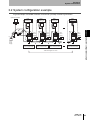
A typical example of a CIDRW controller connected to a plurality of heads is given below.
Upstream controller
Head
"HeadID" "01"
Head
"HeadID" "02"
24V-
24V54321
24V+
24V54321
24V+
24V54321
24V+
24V54321
24V+
24 V
power
supply
SW1-5: Node 1
SW10: Terminator /ON
SW1-5: Node 2
SW10: Terminator /OFF
SW1-5: Node 3
SW10: Terminator /OFF
SW1-5: Nth node
SW10: Terminator /ON
Total cable length: max. 50 m
V700-L21
User's Manual
3.2 System configuration example
24V+
24 V
power
supply
24 V
power
supply
24 V
power
supply
Section 3
24 V
power
supply
Head
"HeadID" "N"
Head
"HeadID" "03"
39
Section 3
System Connections
MEMO
Section 3
3.2 System configuration example
40
V700-L21
User's Manual
Section 4
SECS Protocol Specifications
42
4.2 Protocol specifications
43
4.3 Support attributes
45
4.4 Message specifications
47
4.5 Operating conditions
60
Section 4
4.1 Operation model
SECS Protocol Specifications
V700-L21
User's Manual
41
Section 4
SECS Protocol Specifications
4.1 Operation model
Set the MODE switch to 0 position, and power UP the CIDRW system. The CIDRW system is then initialized,
and then acts according to the state models defined in SEMI E99.
(1) CIDRW state model
The system is running in operating mode.
OPERATING
OPERATIONAL status
IDLE
No service is performed on any head.
BUSY
A service is performed on any head.
Section 4
MAINTENANCE
The system is running in maintenance mode.
* The service will vary by change of state commanded by the host.
NO ALARMS
No alarm condition exists on the CIDRW controller and all the connected heads.
ALARMS
An alarm condition exists.
• In the head detection process during initializing, a faulty head has
been detected or no head has been detected at all.
(This state is cleared only when the system is powered OFF and ON
again, and correct head connection is detected.)
• During data transaction with an ID tag, a faulty head has been
detected.
(Correct state is automatically restored when in the ensuing action,
the faulty state is found to have been cleared.)
• Internal error on CIDRW controller has occurred.
ALARM status
4.1 Operation model
A state where after powering UP, the CIDRW is initializing or detecting
heads, before the CIDRW system can function as intended.
INITIALIZING
(2) IDRW head state model
The head is normally running.
OPERATING
OPERATIONAL status
NOT OPERATING
42
V700-L21
User's Manual
IDLE
No service is performed on any head.
BUSY
A service is performed on any head.
The heads (IDRW heads, link units) needs to be checked for correct
functioning.
* The alarm status with CIDRW is ALARMS.
Section 4
SECS Protocol Specifications
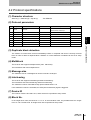
4.2 Protocol specifications
(1) Character structure
Start bit (1) + data bits (8) + stop bit (1)
*Per SEMI E4
(2) Protocol parameters
No.
Symbol
Name
Default
Range
Resolution
-
Device ID
0
0 - 32767
1
T1
Inter-character timeout
0.5s
0.1 - 10s
0.1s
T2
Protocol timeout
10s
0.2 - 25s
0.2s
5
T3
Replay timeout
45s
1 - 120s
1s
6
T4
Inter-block timeout
45s
1 - 120s
1s
7
RTY
Retry limit
3
0 - 31
1
8
M/S
Master/slave
Master
-
-
Baud rate
2
DEVID
3
4
(3) Duplicate block detection
The header of correct block received immediately before is compared with that of currently received
block in order to detect a duplicate block. Whether or not this detection is enabled can be set in setup
mode.
(4) Multiblock
4.2 Protocol specifications
1200,2400,4800,9600,19200,
38400,57600,115200 bps
BAUD
Section 4
9600
1
The receiver side supports multiple blocks (max. 128 blocks).
The transmitter side uses multiple blocks.
(5) Message size
The maximum size of a message that can be received is 32 kbytes.
(6) Interleaving
The receiver side supports interleaving and block interleaving.
The transmitter side uses interleaving and block interleaving.
The maximum number of simultaneously opened transactions is 16.
If this maximum number is exceeded, an SxF0 (abort transaction) signal is triggered.
(7) Device ID
The number of device ID used is one, and a device ID is specified in setup mode.
(8) Block No.
In the single block case, the block No. is 1 or 0. In the multi-block case, the possible block No. ranges
from1 to 128. The block No. for single block case is specified in setup mode.
V700-L21
User's Manual
43
Section 4
SECS Protocol Specifications
(9) Handling of system bytes
A system byte consists of a source ID and a transaction ID.
A source ID is a fixed value and is specified in setup mode.
The initial value of transaction ID is 1, and the maximum value is 0xFFFF. A transaction ID is
incremented every time a primary message is transmitted.
(10) Stalling
The type of stalling when BUSY state is present owing to internal buffer FULL, etc., is "NAK transmit".
(11) Action after timeout detection
T3 or T4 timeout is reported by means of S9F9 message.
Section 4
■ SECS parameters
Parameter
4.2 Protocol specifications
44
Default
Range
Resolution
Dual block detection
1: Perform
1: Perform, 0: Not perform
Source ID
0
0 - 32767
1
Single block No.
1
0, 1
V700-L21
User's Manual
Section 4
SECS Protocol Specifications
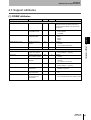
4.3 Support attributes
(1) CIDRW attributes
Attribute name
Description
Access
Requested
Form
Fundamental
Number of heads
RO
Y
20 "00"-"31"
Number of heads connected at the time of
powering ON the CIDRW system (automatic
recognition)
Alarm Status
Current CIDRW substate
of ALARM STATUS
RO
Y
20
0=NO ALARMS
1=ALARMS
Operational Status
Current CIDRW substate
of OPERATIONAL
RO
Y
20
"IDLE"
"BUSY"
"MANT"
Software Revision Level
Revision (version) of
software
RO
Y
20 6byte
"VVV.RR"
* VVV= version, RR=revision
Date Installed
Date where the subsystem was installed
RW
N
20 8byte
Factory setting is " " (spaces)
Device Type
Identifies subsystem as
either CIDR or CIDRW.
RO
N
20 5byte
"CIDRW"
Hardware Revision Level
Revision (version) of
hardware
RO
N
20 6byte
"VVV.RR"
* VVV=version, RR=revision
Maintenance Data
Supplier dependent
RW
N
20 80byte
Factory setting is " " (spaces)
Manufacturer
The name or ID of the
manufacturer
RO
N
20 17byte
"OMRON Corporation"
Model Number
The manufacturer's
model designation
RO
N
20 6byte
"L21 "
(SerialNumber)
Subsystem serial number assigned by the
manufacturer
RO
N
20 max. 20 bytes
* Not yet supported with this CIDRW system
Section 4
Configuration
4.3 Support attributes
Optional
V700-L21
User's Manual
45
Section 4
SECS Protocol Specifications
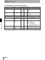
(2) Reader/Writer head attribute definitions
Attribute name
Description
Access
Requested
Form
Fundamental
Head Status
Current state
RO
Y
20
"IDLE"
"BUSY"
"NOOP"
Head ID
Head number 1-31
RO
Y
(multi)
20
"01"-"31"
* "00" represents the CIDRW itself, and must
not be used.
Cycles
Number of read and
write operations performed
RO
N
54 (4-byte unsigned integer)
* Not yet supported with this CIDRW system
Head Condition
Current maintenance
status
RO
N
20
NO: no alarms
NM: Needs maintenance.
RW: Read/write fault
RT: Read/write rate fault
* Not yet supported with this CIDRW system
NP: No power or connection error
(Head Date Installed)
Date this head was
installed
RO
N
20 "YYYYMMDD"
* Not yet supported with this CIDRW system
(Head Maintenance Data)
Supplier dependent
RO
N
20
* Not yet supported with this CIDRW system
Optional
Section 4
4.3 Support attributes
46
V700-L21
User's Manual
Section 4
SECS Protocol Specifications
4.4 Message specifications
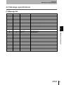
(1) Message list
0
S,H←E
Direction
Abort transaction
Name per SECS II
1
1
S,H→E,reply
On line acknowledge request
1
2
S,H←E
On line data
9
0
S,H→E
Abort transaction
9
1
S,H←E
Unrecognized device ID
9
3
S,H←E
Unrecognized stream type
9
5
S,H←E
Unrecognized function type
9
7
S,H←E
Illegal data
9
9
S,H←E
Transaction timer timeout
9
11
S,H←E
Data too long
18
0
S,H←E
Abort transaction
18
1
S,H→E,reply
Read attribute request
18
2
S,H←E
Read attribute data
18
3
S,H→E,reply
Write attribute request
18
4
S,H←E
Write attribute acknowledge
18
5
S,H→E,reply
Read request
18
6
S,H←E
Read data
18
7
S,H→E,reply
Write data request
18
8
S,H←E
Write data acknowledge
18
9
S,H→E,reply
Read ID request
18
10
S,H←E
Read ID data
18
11
S,H→E,reply
Write ID request
18
12
S,H←E
Write ID acknowledge
18
13
S,H→E,reply
Subsystem command request
18
14
S,H←E
Subsystem command acknowledge
4.4 Message specifications
F
1
Section 4
S
V700-L21
User's Manual
47
Section 4
SECS Protocol Specifications
(2) Data item dictionary
SECS II data item
Name
Format
Value
Section 4
4.4 Message specifications
ATTRID
Attribute ID
20
Attribute name
ATTRVAL
Attribute value
20
Attribute value
MID
Carrier ID
20 (16 bytes fixed)
All characters 00H-0FFH
DATA
Data
20 (8 bytes fixed)
All characters 00H-0FFH
DATALENGTH
Data size
52
8 (fixed)
DATASEG
Data segment
20
"S01", "S02",⋅⋅⋅"S27", "S28"
STATUS
PMInformation
20
NE: normal (fixed)
SSACK
Result information
20
NO: normal
EE: execute error *3
CE: communication error
HE: hardware error*3
TE: tag error *3
List of STATUS
Status
L,4
1.<PM Information>
2.<Alarm Status>
3.<Operational Status>
4.<Head Status> *2
PM Information contains the STATUS value.
CPVAL
State request parameter
20
"OP", "MT", "PS" *1
TARGETID
Target ID
20
"00"-"31"
* "00" represents the CIDRW controller itself.
SSCMD
Subsystem command
20
"Change State"
"Get Status"
"Perform Diagnostics"
"Reset"
*1: "PS" is an extension command of the CIDRW system.
*2: Will be zero-length item if TARGETID is "00" (CIDRW).
*3: "EE", "HE" and "TE" are used only for S18F6, S18F8, S18F10 and S18F12.
<About S9F7 response>
When a message with an illegal format from the upstream controller is received, the S9F7 is returned to the
upstream controller. "Illegal format" refers to a one whose message structure has a problem such as an illegal
attribute, or excessive or insufficient items. In the case of problematic item content, SSACK = "CE"
(communications error) will be returned to the upstream controller.
48
V700-L21
User's Manual
Section 4
SECS Protocol Specifications
(3) Stream/function specifications
S1,F1
On line acknowledge request
S,H→E,reply
Header only
Section 4
On line data
4.4 Message specifications
S1,F2
S,H←E
L,2
1.<MDLN>
2.<SOFTREV>
• Defines an MDLN = Model Number.
• Defines SOFTREV = Software Revision Level.
V700-L21
User's Manual
49
Section 4
SECS Protocol Specifications
S18,F1
Read attribute request
S,H→E,reply
1.<TARGETID>
"00"-"31"
L,2
2.L,n
1.<ATTRID1>
.
n.<ATTRIDn>
• If all the attributes (CIDRW controller or head) are to be read, then set n=0.
Section 4
4.4 Message specifications
S18,F2
Read attribute data
S,H←E
1.<TARGETID>
"00"-"31"
L,4
2.<SSACK>
3.L,n
1.<ATTRVAL1>
.
n.<ATTRVALn>
4.L,s
1.<STATUS1>
.
s.<STATUSs>
• The order of attribute data is in accordance with the attribute ID defined by S18 and F1.
* If reading of all attributes is specified, then unsupported attributes (ATTRVAL) are skipped.
• When specified target is invalid:
n=0, s=0, SSACK = CE (communications error)
• When one or more undefined attributes are included:
n=0, s=0, SSACK = CE (communications error)
• If target =00 and when head attribute is specified, or the CIDRW controller attribute is specified with target < >00:
n=0, s=0, SSACK = CE (communications error)
• When SSACK is other than NO (normal), the List of Status will take a list structure with which the number of items is 0.
50
V700-L21
User's Manual
Section 4
SECS Protocol Specifications
S18,F3
Write attribute request
S,H→E,reply
1.<TARGETID>
Fixed at "00"
L,2
2.L,n
1.L,2
1.<ATTRID1>
2.<ATTRVAL1>
n.L,2
1.<ATTRIDn>
2.<ATTRVALn>
• Since all the HEAD attributes with the CIDRW are R0, the TARGETID is fixed at "00".
Section 4
Write attribute acknowlegde
S,H←E
1.<TARGETID>
Fixed at "00"
4.4 Message specifications
S18,F4
L,3
2.<SSACK>
3.L,s
1.<STATUS1>
.
s.<STATUSs>
• When the specified target is invalid (head):
s=0, SSACK = CE (communications error)
• When one or more undefined attributes or R0 attributes are included:
s=0, SSACK = CE (communications error)
• When illegal attribute data is specified:
s=0, SSACK = CE (communications error)
• When SSACK is other than NO (normal), the List of Status will take a list structure with which the number of items is 0.
V700-L21
User's Manual
51
Section 4
SECS Protocol Specifications
S18,F5
Read request
S,H→E,reply
1.<TARGETID>
"01"-"31"
L,3
2.<DATASEG>
3.<DATALENGTH>
• If all the data of all segments are requested as a block, both DATASEG and DATALENGTH must be zero length items.
• If all the data in a particular segment is requested, DATALENGTH alone is omitted (zero length item or zero).
• When specifying DATASEG and DATALENGTH, it is impossible to choose a DATALENGTH that exceeds the maximum allowable
length of that DATASEG.
• If DATALENGTH whose length is shorter than DATASEG is specified, the data corresponding with that DATALENGTH only is read.
Section 4
4.4 Message specifications
S18,F6
Read data
S,H←E
1.<TARGETID>
"01"-"31"
L,4
2.<SSACK>
3.<DATA>
4.L,s
1.<STATUS1>
.
s.<STATUSs>
• When the specified target is invalid:
DATA item length=0, s=0, SSACK = CE (communications error)
• When an undefined DATASEG is specified, or DATALENGTH is illegal:
DATA item length=0, s=0, SSACK = CE (communications error)
• When reading of all segment data is instructed for a system whose data segments have not yet been defined:
DATA length=0, SSACK = NO
• When SSACK is other than NO (normal), the List of Status will take a list structure with which the number of items is 0.
52
V700-L21
User's Manual
Section 4
SECS Protocol Specifications
S18,F7
Write data request
S,H→E,reply
1.<TARGETID>
"01"-"31"
L,4
2.<DATASEG>
3.<DATALENGTH>
4.<DATA>
Write data acknowledge
S,H←E
1.<TARGETID>
"01"-"31"
4.4 Message specifications
S18,F8
Section 4
• If all the data of all segments are requested as a block, both DATASEG and DATALENGTH must be zero length items.
• If all the data in a particular segment is requested, DATALENGTH alone is omitted (zero length item or zero).
• When specifying DATASEG and DATALENGTH, it is impossible to choose DATALENGTH that exceeds the maximum allowable
length of that DATASEG.
• When a DATALENGTH shorter than the preset length of DATASEG is specified, the data corresponding to that DATALENGTH is written into a lower address.
• The DATALENGTH must coincide with the DATA item length.
• If both DATASEG and DATALENGTH are set to zero length items, the DATA length must coincide with the sum of all the segments.
L,3
2.<SSACK>
3.L,s
1.<STATUS1>
.
s.<STATUSs>
• When the specified target is invalid:
s=0, SSACK = CE (communications error)
• When DATASEG or DATALENGTH is illegal:
s=0, SSACK = CE (communications error)
• When SSACK is other than NO (normal), the List of Status will take a list structure with which the number of items is 0.
V700-L21
User's Manual
53
Section 4
SECS Protocol Specifications
S18,F9
Read ID request
S,H→E,reply
"01"-"31"
S18,F10
Read ID data
S,H←E
1.<TARGETID>
"01"-"31"
Section 4
1.<TARGETID>
4.4 Message specifications
L,4
2.<SSACK>
3.<MID>
4.L,s
1.<STATUS1>
.
s.<STATUSs>
• When the specified target is invalid:
s=0, MID item length = 0, SSACK = CE (communications error)
• When SSACK is other than NO (normal), the List of Status will take a list structure with which the number of items is 0.
54
V700-L21
User's Manual
Section 4
SECS Protocol Specifications
S18,F11
Write ID request
S,H→E,reply
1.<TARGETID>
"01"-"31"
L,2
2.<MID>
• If an MID is defined which is shorter than the preset ID length, the data is written in a lower address, and the NULL (0×00) string is written as remaining data.
Section 4
Write ID acknowledge
S,H←E
1.<TARGETID>
"01"-"31"
4.4 Message specifications
S18,F12
L,3
2.<SSACK>
3.L,s
1.<STATUS1>
.
s.<STATUSs>
• When the specified target is invalid:
s=0, SSACK = CE (communications error)
• When the MID length is faulty:
s=0, SSACK = CE (communications error)
• When SSACK is other than NO (normal), the List of Status will take a list structure with which the number of items is 0.
V700-L21
User's Manual
55
Section 4
SECS Protocol Specifications
S18,F13
Subsystem command request (ChangeState)
S,H→E,reply
1.<TARGETID>
Fixed at "00"
2.<SSCMD>
"Change State"
L,3
3.L,1
1.<CPVAL1>
"OP", "MT", "PS"
• CPVAL1="PS" is a parameter unique to OMRON CIDRW controller, and is used to access setup mode.
Section 4
4.4 Message specifications
S18,F14
Subsystem command acknowledge (ChangeState)
S,H←E
1.<TARGETID>
"00"
L,3
2.<SSACK>
3.L,s
1.<STATUS1>
.
s.<STATUSs>
• When the specified target is invalid:
s=0, SSACK = CE (communications error)
• When SSCMD is invalid:
s=0, SSACK = CE (communications error)
• When the Operational Status is BUSY:
s=0, SSACK = EE (communications error)
• When SSACK is other than NO (normal), the List of Status will take a list structure with which the number of items is 0.
56
V700-L21
User's Manual
Section 4
SECS Protocol Specifications
S18,F13
Subsystem command request (GetStatus)
S,H→E,reply
1.<TARGETID>
"00"-"31"
2.<SSCMD>
"GetStatus"
L,3
3.L,0
Section 4
Subsystem command acknowledge (GetState)
S,H←E
1.<TARGETID>
"00"-"31"
4.4 Message specifications
S18,F14
L,3
2.<SSACK>
3.L,s
1.<STATUS1>
.
s.<STATUSs>
• When the specified target is invalid:
s=0, SSACK = CE (communications error)
• When SSCMD is invalid:
s=0, SSACK = CE (communications error)
• When SSACK is other than NO (normal), the List of Status will take a list structure with which the number of items is 0.
V700-L21
User's Manual
57
Section 4
SECS Protocol Specifications
S18,F13
Subsystem command request (PerformDiagnostics)
S,H→E,reply
1.<TARGETID>
"00"-"31"
2.<SSCMD>
"Perform Diagnostics"
L,3
3.L,0
Section 4
4.4 Message specifications
S18,F14
Subsystem command acknowledge (PerformDiagnostics)
S,H←E
1.<TARGETID>
"00"-"31"
L,3
2.<SSACK>
3.L,s
1.<STATUS1>
.
s.<STATUSs>
• When the specified target is invalid:
s=0, SSACK = CE (communications error)
• When SSCMD is invalid:
s=0, SSACK = CE (communications error)
• When SSACK is other than NO (normal), the List of Status will take a list structure with which the number of items is 0.
58
V700-L21
User's Manual
Section 4
SECS Protocol Specifications
S18,F13
Subsystem command request (Reset)
S,H→E,reply
1.<TARGETID>
Fixed at "00"
2.<SSCMD>
"Reset"
L,3
3.L,0
Section 4
Subsystem command acknowledge (Reset)
S,H←E
1.<TARGETID>
"00"
4.4 Message specifications
S18,F14
L,3
2.<SSACK>
3.L,0
• When the specified target is invalid:
s=0, SSACK = CE (communications error)
• When SSCMD is invalid:
SSACK = CE (communications error)
V700-L21
User's Manual
59
Section 4
SECS Protocol Specifications
4.5 Operating conditions
The acknowledge messages and acknowledge codes (SSACK) for various states are listed below:
State
Message
Section 4
4.5 Operating conditions
60
Function
Initializing
Operating
IDLE
BUSY
Maintenance
S1,F1
Online Request
S1,F0
S1,F2
S1,F2
S1,F2
S18,F11
Write ID
S18,F0
S18,F0
S18,F0
NO
S18,F7
Write Data
S18,F0
NO
NO
S18,F0
S18,F3
Set Attribute
S18,F0
NO
NO
NO
S18,F13(Reset)
Reset
S18,F0
NO
NO
NO
S18,F9
Read ID
S18,F0
NO
NO
NO
S18,F5
Read Data
S18,F0
NO
NO
S18,F0
S18,F13(Perform Diagnostics)
Diagnostics
S18,F0
NO
NO
NO
S18,F13(Get Status)
Get Status
S18,F0
NO
NO
NO
S18,F1
Get Attribute
S18,F0
NO
NO
NO
S18,F13(Change State)
Change State(to MT)
S18,F0
NO
S18,F0
S18,F0
S18,F13(Change State)
Change State(to OP)
S18,F0
S18,F0
S18,F0
NO
S18,F13(Change State)
Change State(to PS)
S18,F0
NO
S18,F0
NO
V700-L21
User's Manual
Section 5
Setup Mode
5.1 Accessing setup mode
62
5.2 How to set up parameters
63
Section 5
Setup Mode
V700-L21
User's Manual
61
Section 5
Setup Mode
In setup mode, the operator can define various parameters such as the operating conditions for CIDRW.
5.1 Accessing setup mode
To access the setup mode, the three methods below are available:
(1) Power up the CIDRW controller with its MODE switch in position 3.
(2) In normal operation mode, send a subsystem command (S18F13 Change State CPVAL1="PS") to
the CIDRW controller.
∗ CPVAL1="PS" is an extended function specific to Model V700-L21 controller, and does not conform to
SEMI standards.
(3) Connect the setup mode startup cable to the SECS port, and
then power UP the CIDRW controller in normal operation mode (MODE switch in position 0).
<Setup mode startup cable connection>
Symbol
Section 5
RD
DOS/V
5.1 Accessing setup mode
#4-40
1
1
2
2
3
Symbol
RD
CIDRW
SD
controller
3
4
4
SG
5
5
6
6
RS
7
7
RS
CS
8
8
CS
9
9
D-SUB
female
Pin No.
SD
PC
9-pin
Pin No.
SG
D-SUB
9-pin
female
#4-40
• Recommended cable: CO-MA-VV-SB 5PX28AWG (Hitachi Cable, Ltd.)
• Recommended connector: socket-Model XM2D-0901 (OMRON), hood-Model XM2S-0913 (OMRON)
In the setup mode, the STATUS indicators will function as listed below:
Status
OPERATING
ALARMS
BUSY
ERROR
Standby for data reception (idling, with correct setup)
Receiving data
Parameter setup failed
: Stably lit,
62
V700-L21
User's Manual
: Unlit,
: Flashing
Section 5
Setup Mode
5.2 How to set up parameters
Various parameters are set up using a terminal software loaded into an upstream controller (PC/AT)
connected to the SECS port of CIDWR controller. The communications parameters for data transaction
between the upstream controller and CIDRW controller are fixed and cannot be altered on the CIDWR
controller side. On the terminal software side, set up the communications parameters, transmission code,
indications, etc., as listed below:
Baud rate
9600 bps
Date length
8 bit
Parity
EVEN
Stop bit
1
Communication control
None
Transmission code
Add a line feed character (LF) to the end of line (ENTER is input).
Indication
Local echo
controller.
SETUP_START <L21 ><XXX.XX,YYY.YY>
The setting-capable parameters are as listed below:
■ Parameter list
Category
Parameter
Tag name
Default
Range
Protocol
Baud rate (BAUD)
S_BAUD
9600
1200,2400,4800,9600,19200,
38400,57600,115200
Protocol
Device ID (DEVID)
S_DEVID
0
0 - 32767
Protocol
Inter-character timeout (T1)
S_T1
0.5s
0.1 - 10s
Protocol
Protocol timeout (T2)
S_T2
10s
0.2 - 25s
Protocol
Reply timeout (T3)
S_T3
45s
1 - 120s
Protocol
Inter-block timeout (T4)
S_T4
45s
1 - 120s
Protocol
Retry limit (RTY)
S_RTY
3
0 - 31
Protocol
Master/slave (M/S)
S_MS
M: Master
M: Master
S: Slave
SECS
Dual block detection
S_DB
1: Perform
1: Perform
2: Not perform
SECS
Source ID
S_SRC
0
0 - 32767
SECS
Single block No.
S_BNO
1
0,1
Service
Baud rate to link unit
C_BAUD
9600
9600,19200,38400
Service
Number of heads count
C_HEAD
0
0 - 31
0
: Auto count
1 - 31 : Number of heads specified
V700-L21
User's Manual
5.2 How to set up parameters
*<"Modelnumber"><"SoftwareRevisionLevel", "HardwareRevisionLevel">
Section 5
Once entering setup mode, the basic screen below will appear on the terminal display of the upstream
63
Section 5
Setup Mode
To set up a parameter, send the following instructions from the terminal software.
Instruction
Format
Action
Parameter definition
"(Tag name)" + "=" + "(setting value)" + CR + LF
Enter the parameter for the tag name.
Parameter change
"::END"
A so far received parameter definition is checked. If
the definition is found to be valid, the parameter setting is altered accordingly.
Comment
"#" + "(Comment)" + CR + LF or CR + LF
This line is ignored as a comment line.
Parameter output
"::GET_PARAM"
A predefined parameter is output.
Reset
"::EXIT"
CIDRW controller is repowered.
First, select the tag name of a parameter being altered and enter a setting value to complete [parameter
definition]. Then, perform [parameter change]. To be able to alter two or more parameters, repeat [parameter
definition] process the necessary number of times, and then execute [parameter change]. After completion of
a setup process, a message and ERROR status indicator indicate the result (success or failure).
■ Status after setup process
Section 5
5.2 How to set up parameters
Normal completion
"SETUP_COMPLETE"
ERROR
The selected parameter was altered as intended.
The values of parameters not specified remain unchanged.
Setup failure
"SETUP_FAILED [2]"
ERROR
An error situation is present. The value of any parameter
remains unchanged. The value in [ ] represents a line where a
first error has been detected. If a parity error is contained in a
received character string, this value will be 0.
: Lit,
: Unlit
After successful completion of setup process, restart the CIDWR controller. As a result, the newly defined
parameters will become valid. To restart, either power OFF and ON again or execute [Reset] command
("::EXIT").
To view the contents of parameters, execute [parameter output] command. All the currently valid parameter
values will be displayed.
64
V700-L21
User's Manual
Section 5
Setup Mode
[Parameter setup example]
➀ Link the CIDRW controller to the upstream controller, and boot up the terminal software. Then,
power UP the CIDRW controller in setup mode.CIDRW
SETUP_START <L21 ><XXX.XX,YYY.YY>
_
➁ For a parameter being altered, execute parameter definition.
SETUP_START <L21 ><XXX.XX,YYY.YY>
S_BAUD=19200 [ENTER]
S_DEVID=1 [ENTER]
S_BNO=0 [ENTER]
* [ENTER] does not appear on
the screen.
_
Once a first parameter is defined, the ALARMS status indicator flashes.
➂ Execute parameter change process. The entered parameter is checked and written into the CIDRW
Section 5
controller.
* [ENTER] does not appear on
the screen.
➃ Once setup process is complete, a message indicating the result appears.
SETUP_START <L21 ><XXX.XX,YYY.YY>
S_BAUD=19200
S_DEVID=1
S_BNO=0
::END
SETUP_COMPLETE
_
5.2 How to set up parameters
SETUP_START <L21 ><XXX.XX,YYY.YY>
S_BAUD=19200
S_DEVID=1
S_BNO=0
::END [ENTER]
The ALARMS status indicator stably lights.
➄ Once the whole setup procedure is successfully complete, restart the CIDRW controller in normal
operating mode.
It will be convenient to create a text file such as a one shown below and transmit the file using the text
file send function of the terminal (upstream controller).
Prm.txt
#Parameter Setting File for SystemA
#Protocol
S_BAUD=19200
S_DEVID=1
#SECS
S_BNO=0
::END
V700-L21
User's Manual
65
Section 5
Setup Mode
[Parameter check example]
➀ Select a parameter output being altered.
SETUP_START <L21 ><XXX.XX,YYY.YY>
::GET_PARAM [ENTER]
➁ The contents of the current parameter settings will be displayed.
Section 5
SETUP_START <L21 ><XXX.XX,YYY.YY>
::GET_PARAM
S_BAUD=19200
S_DEVID=1
S_T1=0.5
S_T2=10.0
S_T3=45
S_T4=3
S_RTY=3
S_MS=M
S_SRC=0
S_BNO=0
C_BAUD=9600
C_HEAD=0
::END
_
5.2 How to set up parameters
66
V700-L21
User's Manual
* [ENTER] does not appear on
the screen.
Section 6
Reference
6.1 Processing Time (information only)
68
6.2 Performance Data Based on Operating Conditions
(information only)
69
6.2.1 Effect of nearby metal object onto IDRW head
69
6.2.2 Spacing for installing IDRW heads
70
6.2.3 Effect of inclination of ID tag
71
Section 6
Reference
V700-L21
User's Manual
67
Section 6
Reference
6.1 Processing Time (information only)
As illustrated below, the processing time with OMRON CIDRW system begins with the trailing end of a
request message sent from the upstream controller to the CIDWR controller and lasts until the CIDRW
controller sends a request send (ENQ) to the upstream controller.
ENQ
OT
Request message
OT
Upstream
controller
CIDRW
EOT
EOT
ENQ
Acknowledge message
Processing time
Time
The processing time varies depending on the content of request send and current process load on the
CIDRW. The processing times are listed below by request messages that were sent with no open transaction
Section 6
present.
Request message
Processing time [unit: ms]
6.1 Processing Time (information only)
Single segment read request
<S18,F5>
Approx. 900
All segments read request
<S18,F5>
Approx. 3,600
Single segment write request
<S18,F7>
Approx. 950
All segments write request
<S18,F7>
Approx. 3,900
ID read request
<S18,F9>
Approx. 950
ID write request
<S18,F11>
No ID tag (common to all messages)
Approx. 1,000
Approx. 1,200
* These values are based on the assumption that the Baud rate for the CIDRW controller and link unit is 9600 bps.
68
V700-L21
User's Manual
Section 6
Reference
6.2 Performance Data Based on Operating Conditions
(information only)
The maximum effective communication distance of an IDRW head varies depending on the operating
conditions (presence/absence of a nearby metal object, spacing between the IDRW heads, etc.). This section
describes the effect of varying operating conditions on the effective communication distance. Before operating
the IDRW heads, study the information in this section. The values mentioned here are given only as a
guideline.
6.2.1 Effect of nearby metal object onto IDRW head
■ Model V700-HMD13
When mounting the Model V700-HMD13
, make sure that the communication surface of IDRW head
is not below the top surface of sheet metal top panel (mounting bracket). Otherwise, the effective com-
Sheet metal top panel
(mounting bracket)
(mounting bracket)
■ Model V700-HMD11-1
A metal object located in the vicinity of the Model V700-HMD11-1 decreases the effective communication distance of the IDRW head. The correlation between the distance between iron object and IDRW
Max. communication distance (data without
nearby metal is taken as 100%) Y (%)
head and the effective communication distance (read/write, misalignment of ±0 mm) is plotted below.
100
Metal object
80
X
60
X
X
40
20
X
0
0
20
40
60
80
6.2 Performance Data Based on Operating Conditions (information only)
Sheet metal top panel
Section 6
0mm or greater
munication distance will decrease.
100
Distance to nearby metal X (mm)
V700-L21
User's Manual
69
Section 6
Reference
6.2.2 Spacing for installing IDRW heads
When two or more IDRW heads are connected to one CIDRW controller unit, there is no limitation on the
spacing of antenna sections since all the IDRW heads do not handle a command simultaneously.
If IDRW heads in an individual CIDRW system are installed in close vicinity, and when these IDRW heads are
simultaneously processing a command, mutual interference can occur across the IDRW heads, possibly
leading to total inability of communication or loss in effective communication distance despite presence of
tags. To avoid such a problem, be sure to install the antenna sections at the intervals specified below.
■ Model V700-HMD13
1000 mm or greater
1000 mm or greater
1000 mm or greater
Section 6
■ Model V700-HMD11-1
➀ Side-by-side configuration
6.2 Performance Data Based on Operating Conditions (information only)
410 mm or greater
410 mm or greater
410 mm or greater
➁ Face-to-face configuration
460 mm or greater
460 mm or greater
70
V700-L21
User's Manual
Section 6
Reference
6.2.3 Effect of inclination of ID tag
Mount the IDRW head and ID tag as vertical as possible. The IDRW head or ID tag remains capable of
communication even if installed inclined. However, in this situation, a shorter communication distance will
result. The correlation between inclination and effective communication distance is summarized below.
■ Model V700-HMD13
ID tag: V700-D23P41
Communication distance (value with zero inclination is taken as 100%)
Inclination of ID tag θ (degrees)
θ
Communication
distance
Communication
distance
0
15
30
45
60
100%
95%
90%
85%
80%
Section 6
ID tag: V700-D23P41
Communication distance
(value with zero inclination is taken as 100%)
Inclination of ID tag θ (degrees)
θ
Communication distance
0
20
40
60
100%
96%
91%
85%
Communication
distance
V700-L21
User's Manual
6.2 Performance Data Based on Operating Conditions (information only)
■ Model V700-HMD11-1
71
Section 6
Reference
MEMO
Section 6
6.2 Performance Data Based on Operating Conditions (information only)
V700-L21
User's Manual
72
Section 7
Troubleshooting
7.1 No acknowledge message (Acknowledge message not
yet received)
74
7.2 Acknowledge message received (other than
SSACK="NO")
75
Section 7
Troubleshooting
V700-L21
User's Manual
73
Section 7
Troubleshooting
If a fault should occur, first thoroughly study the symptom in order to be able to correctly judge the
reproducibility of a problem, and interaction with other associated equipment. Thus, find an appropriate
remedy.
7.1 No acknowledge message (Acknowledge message
not yet received)
State of indicators (
POWER
OPERATING
: lit,
ALARMS
: unlit,
: flashing)
BUSY
ERROR
Typical checkpoint
24 VDC power supply
* The CIDRW controller may have been damaged.
Contact the manufacturer.
• MODE switch setting
* If the MODE switch is found to be correctly set, the
CIDRW controller may have been damaged. Contact
the manufacturer.
* The CIDRW controller may have been damaged.
Contact the manufacturer.
• MODE switch setting
• MODE switch setting
• MODE switch setting
• Cable connections (the wiring connections are configured for accessing the parameter setup mode?)
Section 7
• MODE switch setting
<MODE switch is in correct position>
• Communications parameters for transactions
between CIDRW controller and upstream controller
(Baud rate, character structure, etc.)
• Node No. setting for link unit (particular node No. has
been assigned to two or more link units)
7.1 No acknowledge message (Acknowledge message not yet received)
(Acknowledge message is not yet verified)
• MODE switch setting
• Power supply to link unit
• Baud rate setting for link unit
• Node No. setting for link unit (particular node No. has
been assigned to two or more link units)
• Cable connections and wiring between CIDRW controller and link unit
• Connections of IDRW heads, and wiring for extension
cable
• Routing of various cables (adverse effect by external
noise interference)
74
V700-L21
User's Manual
Section 7
Troubleshooting
7.2 Acknowledge message received (other than
SSACK="NO")
Acknowledge
Typical checkpoint
• Status conditions at the time a message was issued.
Ex.: Write ID (S18F11) in Operating mode, or a message during initializing
S9F7
• Problematic message structure such as illegal attribute, excessive/insufficient items
SSACK="CE"
• Wrong item contents in message
Ex.: Node No. as "Head ID" was assigned to a head that was not yet registered.
• Connection of RS-485 cable between link units (head not yet detected)
• Baud rate setting for link unit (head not yet detected)
• Node No. setting for link unit (particular node No. has been assigned to two or more link units, and correct
link unit cannot be detected)
• Routing of cable between upstream controller and CIDRW controller (adverse effect by external noise
interference)
• Noise environment around the power line of CIDRW controller
SSACK="EE"
• Mounting distance and inclination between ID tag and IDRW head(s)
• Noise environment around IDRW head
• Spacing to IDRW head connected to another CIDRW system
SSACK="HE"
• Connection of IDRW head, and wiring connections of extension cable
• Cable connection and wiring connections between CIDWR controller and link unit
• Power supply to link unit
• Setting of terminator on link unit
• Routing of various cables (adverse effect by external noise interference)
• Node No. setting for link unit (particular node No. has been assigned to two or more link units)
• Noise environment around power line
SSACK="TE"
• Model and specifications of ID tag used
• Setting of ID tag used (write protect, etc.)
• Operating environment of tag (damaged ID tag by misoperation or misuse)
• Life of ID tag in terms of number of rewrite operations (100,000 cycles)
Section 7
S×F0
7.2 Acknowledge message received (other than SSACK="NO")
V700-L21
User's Manual
75
Section 7
Troubleshooting
MEMO
Section 7
7.2 Acknowledge message received (other than SSACK="NO")
V700-L21
User's Manual
76
Revision History
A manual revision code is suffixed to the manual ID located to the bottom right corner of front cover and to the
bottom left corner of back cover.
Catalog No. Z214-E1-01B
Revision code
Revision note
Data
A
September 2000
B
February 2005
Revised contents
1st
version
Warranty and liability information added to beginning of manual, signal word and
alert symbols modified, and style of safety information in the body of the manual
changed.
ëÊ 6 èÕ
V700-L21
User's Manual
77
This document provides information mainly for selecting suitable models. Please read the Instruction Sheet carefully for information that the user must understand and accept before
purchase, including information on warranty, limitations of liability, and precautions.
OMRON Corporation
Industrial Automation Company
Application Sensors Division
Sensing Devices and Components Division H.Q.
Shiokoji Horikawa, Shimogyo-ku,
Kyoto, 600-8530 Japan
Tel: (81)75-344-7068/Fax: (81)75-344-7107
Regional Headquarters
OMRON EUROPE B.V.
Sensor Business Unit,
Carl-Benz-Str. 4, D-71154 Nufringen,
Germany
Tel: (49)7032-811-0/Fax: (49)7032-811-199
OMRON ELECTRONICS LLC
1 East Commerce Drive, Schaumburg, IL 60173
U.S.A.
Tel: (1)847-843-7900/Fax: (1)847-843-8568
Authorized Distributor:
OMRON ASIA PACIFIC PTE. LTD.
83 Clemenceau Avenue,
#11-01, UE Square,
239920 Singapore
Tel: (65)6835-3011/Fax: (65)6835-2711
OMRON CHINA CO., LTD. BEIJING OFFICE
Room 1028, Office Building,
Beijing Capital Times Square,
No. 88 West Chang'an Road,
Beijing, 100031 China
Tel: (86)10-8391-3005/Fax: (86)10-8391-3688
Cat. No. Z214-E1-01B
Printed in Japan
0205-0.3C (0900) (M)