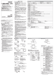
Download 形V640-HAM11-V3-1
Transcript
以下に示す項目は安全を確保するために、
必ず守ってください。
(1)引火性・爆発性ガスの環境では使用しないでください。
(2)操作・保守の安全性を確保するため、
高圧機器や動力機器から離して設
置してください。
(3)取付けにおいて、
ねじの締め付けは確実に行ってください。(推奨:1.2N・m)
(4)ケースの隙間から水や針金などの異物を入れないでください。
火災や感電
の原因となります。
(5)この製品を分解したり、
修理、
改造しないでください。
(6)廃棄するときは、
産業廃棄物として処理してください。
(7)配線作業、
ケーブル類、
CIDRWヘッドを着脱する際は、
アンプユニットの電
源を切ってから行ってください。
(8)通風スペースを十分にとってください。
(9)発熱量の高い機器
(ヒーター,
トランス,
大容量の抵抗など)
の近くに取り付け
ることは避けてください。
(10)万一、
製品に異常を感じた時には、
すぐに使用を中止し、
電源を切った
上で、
当社支店・営業所までご相談ください。
使用上の注意
1.
設置環境について
次のような場所に設置してください。
(1)直射日光があたらない場所
(2)腐食性ガス、塵埃、金属粉、塩分がない場所
(3)温度変化が急激ではなく結露しない場所(仕様の範囲内であること)
(4)湿度が高くなく、結露しない場所(仕様の範囲内であること)
(5)振動や衝撃が本体に直接伝わらない場所(仕様の範囲内であること)
(6)水・油・化学薬品の飛沫がない場所
(7)使用温度が仕様で定められている範囲内の場所
2.
保管環境について
(1)保管時は、保存周囲温度/湿度を守り、保管してください。
3.
配線作業について
(1)本書で指定した電源電圧で使用してください。
(2)電源端子の+-を逆接続しないでください。
■はじめに
本製品は、
Texas Instruments(TI製)IDタグ
(RI-TRP-DR2B(-30) /
RI-TRP-WR2B(-30))
に対して、
データの読み書きを行うことが可能なリーダラ
イタのアンプユニットです。
■一般仕様
項目
電源電圧
消費電流
保護構造
周囲温度
周囲湿度
絶縁抵抗
耐電圧
耐振動
耐衝撃
過電圧カテゴリー
取付け方法
CIDRWヘッド
適応規格
仕様
形V640-HAM11-V3-1
DC24V +10% -15%
150 mA以下
IP20 (IEC60529規格)
動作時:0∼+40℃ 保存時:-15∼+65℃
(氷結しないこと)
動作時・保存時:35∼85%RH
(結露しないこと)
20MΩ以上(DC100Vメガによる)
(電源端子−フレームグランド端子間に印加)
AC1000V(50/60 Hz、1分間)で検出電流5 mA以下
(電源端子−フレームグランド端子間に印加)
周波数10∼150 Hz,複振幅 0.20 mm,加速度15 m/s2上下、
前後、左右各方向に1掃引8分で10掃引
150 m/s2の衝撃を上下、左右、
前後の各方向に3回、計18回
カテゴリーⅠ
4点 M4ねじ止め (ねじ締め付けトルク 1.2 N・m)
形V640-HS61
欧州 / 米国 / カナダ / 中国 / 韓国 / 台湾 / シンガポール
■商品の外観と各部の名称
上位機器との通信またはIDタグとの交信中に
異常が発生した場合に点灯します。
(18.2)
46
56
80
(22.5) (12)
6.8
6.8
6.8
0.6
160
175
185
(32.5)
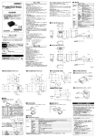
RS-232C コネクタ
DIPスイッチ
4-φ4.5( 取付穴)
(11.5)
(4.2)
アンプユニッ
トの号機番号や各種動作条件の設定を行います。
(1)
No.
名 称
1
号機番号設定1
01 ∼31 No.1がLSB、No.5がMSB
内 容(□内が工場出荷時状態)
2
3
号機番号設定2
号機番号設定3
すべてONの場合、1:1手順 として動作します。
4
号機番号設定4
5
号機番号設定5
6
通信速度設定1
7
通信速度設定2
38400/19200/ 9600 / 4800bps
[ON,ON][ON,OFF][OFF,OFF][OFF,ON] : [No7,No6]
8
空き
必ずOFFにしてご使用ください
175±0.5
4-M4
取付穴加工寸法
OFF / ON
材質
OFF / ON
※RS-485終端抵抗はマルチドロップの両端のユニットのみをON、
それ以外のユニットはOFFに設定してください。
1台のみを使用する場合にはONとしてください。
●24V電源供給端子(①)
・推奨ケーブル: AWG24∼20のケーブル
・推奨コネクタ
: 形1-178288-3 (タイコエレクトロニクスアンプ㈱製)
・推奨コネクタピン: 形175217-3 (タイコエレクトロニクスアンプ㈱製)
・推奨24V電源: 形S8VS-01524
(オムロン㈱製)
(上記推奨コネクタ・コネクタピンはV640−A90
(別売)
に同梱しています。)
コネクタピンを圧着する専用工具として、以下の製品をご使用ください。
形919601-1 (タイコエレクトロニクスアンプ㈱製)
詳細については、
メーカにお問合せください。
■RS−485ポート用ケーブルについて
・推奨ケーブル: 形MVVS 2CX0.5SQ (立井電線㈱製)
・推奨圧着端子: 形AI0.5-8WH (フェニックスコンタクト㈱製)
※同一端子にケーブル2線を接続する場合の圧着端子として以下の製品を
推奨します。
形AI-TWIN2×0.5-8WH (フェニックスコンタクト㈱製)
圧着端子を圧着する専用工具として、以下の製品をご使用ください。
形CRIMPFOX UD6 (フェニックスコンタクト㈱製)
詳細については、
メーカにお問合せください。
■ケーブル配線方法
(RS−485ポート用ケーブル)
①ケーブルの被覆をむいた部分に圧着端子を装着します。
次に、
コネクタの向きに気を付けながら、各線をコネクタの各穴に差し込みます。
②コネクタのケーブル固定用のネジを、線ごとにしっかり締付けてください。先だ
けが細くなっている通常のドライバでは、途中でつかえて奥まで入りません。太
さが一定の小型のマイナスドライバを使用してください。 ケーブル固定用のね
じは、適正締付けトルク(約0.3N・m)で締付けてください。
側面
正面
専用ドライバとして下記の製品があります(別売)
オムロン㈱製:形XW4Z-00C
先端の形状:
0.6mm
PC+ABS
(単位:mm)
※取付け時のM4ねじ適正締め付けトルクは1.2N・mです。
ご使用に際してのご承諾事項
①安全を確保する目的で直接的または間接的に人体を検出する用途に、本製品を使用
しないでください。同用途には、当社センサカタログに掲載している安全センサをご使用
ください。
②下記用途に使用される場合、当社営業担当者までご相談のうえ仕様書などによりご確
認いただくとともに、定格・性能に対し余裕を持った使い方や、万一故障があっても危
険を最小にする安全回路などの安全対策を講じてください。
a)屋外の用途、
潜在的な化学的汚染あるいは電気的妨害を被る用途
またはカタログ、
取扱説明書等に記載のない条件や環境での使用
b)原子力制御設備、
焼却設備、
鉄道・航空・車両設備、
医用機械、
娯楽機械、
安全装置、
および行政機関や個別業界の規制に従う設備
c)人命や財産に危険が及びうるシステム・機械・装置
d)ガス、
水道、
電気の供給システムや24時間連続運転システムなどの
高い信頼性が必要な設備
e)その他、
上記 a) ∼ d) に準ずる、
高度な安全性が必要とされる用途
*上記は適合用途の条件の一部です。当社のベスト、総合カタログ・データシート等最新版
のカタログ、
マニュアルに記載の保証・免責事項の内容をよく読んでご使用ください。
インダストリアルオートメーションビジネスカンパニー ●製品に関するお問い合わせ先
お客様相談室
0120-919-066
クイック
オムロン
携帯電話・PHS・IP電話などではご利用いただけませんので、
下記の電話番号へおかけください。
電話
055-982-5015(通話料がかかります)
■営業時間:8:00∼21:00 ■営業日:365日
●FAXやWebページでもお問い合わせいただけます。
3.5mm
③ケーブルに取付けたコネクタを、アンプユニットに接続します。ア
ンプユニット側のコネクタと、ケーブル側のコネクタの向きを合わ
せ、しっかりと最後まで差し込んで固定用ネジを締付けてください。
●RS−232Cポート
(③)
RS-232Cを使用して上位機器、
CIDRWコントローラ形V700−L22と接続す
るためのポートです。
55.5
IDタグとの交信が正常終了した場合に点灯します。
テストモード
10 RS-485終端抵抗
© OMRON Corporation 2010 All Rights Reserved.
安全上の要点
リンクユニットが正常に動作中に点灯します。
上位機器からのコマンド処理中に点灯します。
●設定DIP-SW
(⑨)
9
* 2 1 4 7 2 7 5 - 6 B *
4-動作表示灯
RS-485 コネクタ
4つのLED(RUN、
COMM、
NORM、
ERROR)でアンプユニットの動作状態を表します。
RUN
COMM
NORM
ERROR
DC電源 コネクタ
(5.7)
(32.5)
43
このたびは、
本製品をお買い上げいただきまして、
まことにありがとう
ございます。ご使用に際しては、
次の内容をお守りください。
・ 電気の知識を有する専門家がお取り扱いください。
・ この取扱説明書をよくお読みになり、
十分にご理解のうえ、
正しく
ご使用ください。
・この取扱説明書はいつでも参照できるよう大切に保管してください。
・詳細につきましては、
ユーザーズマニュアルをご参照ください。
(30.2)
(15.8)
5
取扱説明書
●動作表示灯
(④∼⑦)
■外形寸法
46±0.5
アンプユニット
●RS−485ポート
(②)
一台の上位機器、
CIDRWコントローラから複数のアンプユニットを接続する
場合に、他のアンプユニットのRS−485ポートと接続します。
RS−485ポート
に直接、上位機器を接続することは可能です。
ただし、同時に、
RS−232C
ポートは使用できません。
●CIDRWヘッド接続ポート
(⑧)
CIDRWヘッドを接続するための専用ポートです。
(13)
(12) (17.75)
V640-HAM11-V3-1
形
(3)高圧線や動力線と同一配線官で使用しないでください。
(4)静電気による破損を防ぐため、端子部分やコネクタ内部の信号線に触
れる場合は、
リストラップなどを使用して、帯電防止措置を行ってください。
(5)CIDRWヘッドを着脱する際は、
コネクタに過度な荷重を加えないでください。
(6)アンプユニットに適合する正しいCIDRWヘッドを取り付けてください。
4.
清掃について
(1)市販のアルコールをご使用ください。
(2)シンナー、
ベンジン、
ベンゼン、
アセトン等の有機溶剤は樹脂部分やケース
塗装を溶かしますので、
使用しないでください。
5.
電源、
接地線について
(1)GR
(フレームグランド)
端子は、
必ずD種接地
(従来の第3種接地)
してお
使いください。性能劣化の原因となります。
6.
交信性能
(交信領域・交信時間)
について
(1)CIDRWヘッド周囲の金属や、
ノイズ、
温度、
等の要因により交信性能が
変化しますので、
実際にご使用になる環境において、
確認をお願いします。
(2)IDタグにより、交信領域が変化しますので、余裕を持った設置をお願いします。
7.
取付けについて
(1)この製品は、134kHzの周波数帯を使用してID タグと交信を行っていま
す。
トランシーバ、
モータ、
モニタ装置、電源(電源IC)などの中には、ID タグ
との交信に影響を与える電波( ノイズ) を発生するものがあります。
このよ
うなものの近くでご使用になる場合は、事前に影響を確認してください。
(2)ノイズの影響を最小限とするため、周辺に配置された金属体はD種接地
(従来の第3種接地)をしてください。
(3)CIDRWヘッド取付け時のねじ締めは確実に行ってください。(推奨:0.6N・m)
(4)複数のCIDRWヘッドを隣接設置される場合、相互干渉により交信性能が
低下する恐れがあります。相互干渉が発生しないよう事前に十分な検証を
実施してください。。
8.
ねじ止め用接着剤について
(1)ねじ止め用接着剤(ねじロック)は樹脂部分を劣化させ、割れを発生させ
る可能性があります、樹脂部分のねじや、樹脂製ワッシャの部分には使
用しないでください。
9.
製品起動時の注意事項
(1)製品が故障する恐れがありますので、
電源投入後やモード切替時、
リセッ
ト等による製品起動中には、
電源を切らないでください。
④コネクタを取り外す場合は、固定ネジ2ヶ所を完全に緩めてから、
コネクタの突起部を持ってまっすぐに引抜いてください。抜けにく
いときはアンプユニット本体を押さえて引抜いてください。
FAX
055-982-5051 / www.fa.omron.co.jp
●その他のお問い合わせ
納期・価格・サンプル・仕様書は貴社のお取引先、または貴社
担当オムロン販売員にご相談ください。
オムロン制御機器販売店やオムロン販売拠点は、Webページで
ご案内しています。
A r 2 0 1 2 年 8月
Thank you for selecting OMRON product. This sheet primarily describes precautions required in installing and
operating the product.
Before operating the product, read the sheet thoroughly to
acquire sufficient knowledge of the product. For your convenience, keep the sheet at your disposal.
TRACEABILITY INFORMATION:
Representative in EU:
Omron Europe B.V.
Wegalaan 67-69
2132 JD Hoofddorp,
The Netherlands
Manufacturer:
Omron Corporation,
Shiokoji Horikawa, Shimogyo-ku,
Kyoto 600-8530 JAPAN
Ayabe Factory
3-2 Narutani, Nakayama-cho,
Ayabe-shi, Kyoto 623-0105 JAPAN
© OMRON Corporation 2010 All Rights Reserved.
PRECAUTION FOR SAFE USE
1.Ensure safety, be absolutely sure to follow the instructions below:
(1) Never use the product in an environment where combustible or explosive
gas is present.
(2) Please separate from a high-pressure equipment and the power
equipment to secure the safety of the operation and maintenance.
(3) In the installation, please tighten the screw surely. (Recommended 1.2N・m)
(4) Please do not insert foreign bodies such as water and the wires from the
space of the case.
(5) Please do not dismantle, repair or modify this product.
(6) Please process as industrial waste when you abandon this product.
(7) When you work on wiring and put on and take off cables, CIDRW head,
please perform it after switching off this product.
(8) Provide enough space around this product for ventilation.
(9) Please avoid installing this product near the machinery (a heater, a
transformer, large-capacity resistance) that has high the calorific value.
(10) Please talk to our office by any chance after you cancel use immediately
when you felt abnormality to this product, and having switched it off.
PRECAUTION FOR CORRECT USE
1.About installation site
Do not install this product in the locations subject to the following conditions.
(1)Place where direct sunshine strikes
(2)Place with corroded gas, dust, metallic powder, and salinity
(3)Place with condensation due to rapid temperature fluctuations.
(4)Place with condensation due to high humidity.
(5)Place where vibration and impact more than being provided by
specification are transmitted directly to main body.
(6)Place with spray of water, oil, and chemical medicine.
(7)The working temperature is within the range stipulated in the specifications.
2.About depository site
(1) Please follow the save ambient temperature / humidity, and keep this product.
3.About wiring
(1)Use the power supply voltage specified in this cocument.
(2)Ensure correct polarity when connecting to the +/- power supply terminals.
(3)Do not run high-voltage lines and power lines though the same conduit.
(4)To avoid static-induced failure, wear a wrist band or equivalent means
to release a static charge before touching a terminal or a signal line
within a connector.
(5)When you put on and take off a CIDRW head, please do not add
excessive power to a connector.
(6)Please connect the correct CIDRW head to the amplifier unit.
CIDRW controller can be used to read the data from TI ID tag: RI-TRP-DR2B(-30) /
RI-TRP-WR2B(-30) and write the data to.
■General specifications
Characteristic
Supply voltage
Current consumption
Protection rating
Ambient
temperature
Ambient
humidity
Insulation
resistance
Dielectric
Vibration
resistance
Shock resistance
Environmental
pollution degree
Over voltage category
Mounting system
CIDRW head
Applied standards
Specification
V640-HAM11-V3-1
24 VDC, +10%, -15%
150 mA max
IP20 (IEC 60529)
Operating: 0℃ to +40℃ Storage: -15℃ to +65℃
(No freezing, No dew condensation)
Operating/ Storage: 35% to 85%
(No freezing, No dew condensation)
20MΩ min. (100V DC for appliance)
(between power supply terminal and
frame grounding terminal)
1000V AC (50/60Hz, for 1 min.)
leak current consumption 5mA max.
(between power supply terminal and
frame grounding terminal)
10 to 150Hz, 0.20mm double amplitude,
acceleration 15m/s2, with 10 sweeps of
8min each in 3 directions
150m/s2, 3 times each in 6 directions
Degree 2
CategoryⅠ
Secured with four M4 screws.
(tightening torque:1.2 N・m)
V640-HS61
Europe / USA / Canada / China / Korea / Taiwan /
Singapore
24VDC power terminals
OPERATING
INDICATOR
(32.5)
46
56
80
(12)
6.8
6.8
6.8
(22.5)
0.6
160
175
185
RS-232C port
Description
Meaning (Content within a box
represents factory-setting)
01∼31 No. 1 is LSB, and No. 5 is MSB.
When all switches are ON,this amplifier
unit selects 1:1 protocol.
1 Node No.1
2 Node No.2
3 Node No.3
4 Node No.4
5 Node No.5
6 Baud rate setting 1
38400/19200/ 9600 / 4800bps
7 Baud rate setting 2
[ON,ON][ON,OFF][OFF,OFF][OFF,ON] : [No7,No6]
Reserved
8
Please turn off this SW.
OFF / ON
9 Test mode
10 RS-485 terminator
OFF / ON
・Set the RS-485 terminator setting to ON for the amplifier units on both
ends of multidrop, and to OFF for other units.
If only one amplifier unit is operated, set the terminator setting to ON.
●24VDC power terminals (1)
・Recommended cable : AWG20 - 24
・Recommeded connector : Model 1-178288-3 (Tyco Electronics Co.)
・Recommended compression ring : Model 175217-3
(Tyco Electronics Co.)
(These connector and compression ring are supplied with model V640-A90.)
・Recommended 24 V power supply : Model S8VS-01524(OMRON)
*Use the product below as a crimping tool for crimping the compression ring.
Model 919601-1 (Tyco Electronics Co.)
■Cables for RS-485 port
・Recommended cable : Model MVVS 2CX0.5SQ
(Tachii Densen Co.)
・Recommended compression ring : Molde AI0.5-8WH (Phoenix Contact Co.)
*The following product is recommended as a compression ring for
connecting two cables to one terminal. Model AI-TWIN2 ~0.5-8WH
(Phoenix Contact Co.)
*Use the product below as a crimping tool for crimping the compression ring.
Model CRIMPFOX UD6 (Phoenix Contact Co.)
■How to connect cables
Fit a compression ring to the stripped section of each cable.
Next, being sure of the connector orientation, insert each
cable into a corresponding hole on the connector.
Securely fasten each cable using the cable locking screw on the
connector.
An ordinary screwdriver whose shank is tapered at the tip does not go all
the way into the hole. Use a miniature flat-blade screwdriver with a
straight shank. Tighten the cable locking screws at an appropriated
tightening torque (approx. 0.3 N・m).
Side view Front view
The following purpose-built screwdriver is available:
OMRON: Model XW4Z-00C
From of drip:
0.6mm
3.5mm
Connect the connector to the amplifier unit together with the cables.
Match the orientation of amplifier unit side connector with that of cable side
connector, insert the cable side connector all the way, and then tighten the
connector lock screws.
When removing the connector, fully loosen the two lock screws and draw out it
straight by holding the protrusions on connector.
If the connector does not easily come loose, draw it out while holding down the
link unit proper.
DIP SWITCH
4-�4.5 dia.
(MOUNTING HOLES)
(11.5)
(4.2)
(1)
●Setup DIP-SW (9)
This switch array allows the operator to assign ID No. to amplifier unit
and define various operating conditions.
No.
(18.2)
55.5
RS-485 port
(5.7)
(32.5)
43
INSTRUCTION SHEET
●RS-232C port (3)
This port is for connection to the host or the CIDRW controller: V700-L22
according to RS-232C interface standard.
●RS-485 port (2)
If two or more Amplifier units are connected to one RS-232C port of a
host or a CIDRW controller: model V700-L22, this RS-485 port is
connected to a RS-485 port on another amplifier unit. An RS-485 port (if
any) on the host can be connected to this port. However the RS-232C port
and the RS-485 port are unable to be used at the same time.
●CIDRW head connection port (8)
A port dedicated to connection of a CIDRW head.
●Status indicators (4 -7)
Four indicator lamps (RUN, COMM, NORM, ERROR) indicate the
current operating status of the amplifier unit.
RUN
Remains stably lit as long as the link unit is operating normally.
COMM Remains lit during the communication with a host or an ID tag.
Lights when the communications with an ID tag are successful.
NORM
ERROR Lights when the communications with an host or an ID tag are failed.
(30.2)
(15.8)
5
Amplifier Unit
■Dimensions
175±0.5
46±0.5
V640-HAM11-V3-1
■Names and functions
(13)
(12) (17.75)
Model
4.About cleaning
(1)Use alcohol to clean this product.
(2)NEVER use an organic solvent such as thinner, benzene, acetone or
kerosene, as it will attack resin components or case coating.
5.Power and Graound Cables
(1)Use an appropriate ground. An insufficient ground can affect this
product operation or result in damage to this product.
6.About the communication range and time
(1)Do the communication test with Transponder in the installation
environment because the metal, noise and ambient temperature around
CIDRW head damage to the communication range and time.
(2)Install CIDRW head and ID tag in the appropriate distance because the
communication range can change by the difference of ID tag
specifications.
7.Using Precaution
(1)While you perform network / web password setting, please do not
switch off this product.
8.About mounting
(1)This product communicates with ID Tags using the 134 kHz frequency
band. Some transceivers, motors, monitoring equipment, and power
supplies (power supply ICs) generate electrical waves (noise) that
interfere with communications with ID Tags, If you are using the
product in the vicinity of any of these devices, check the effect on
communications in advance.
(2)In order to minimize the effects of noise, ground nearby metal bodies
with a grounding resistance not exceeding 100 ohms.
(3)When multiple CIDRW Heads are mounted next to each other,
communications performance could be impaired by mutual
interference. Read and follow the information in this manual on mutual
interference when installing multiple heads.
(4)When mounting CIDRW Heads, tighten the screws tightly.
(Recommended 0.6N・m)
9.Startup precaution
(1)Never turn OFF the power supply while the CIDRW Controller is
starting, including when power is turned ON, when the mode is
changed, or when the CIDRW Controller is being reset. Doing so may
damage the CISRW Controller.
10.Part 15 of the FCC Rules
FCC WARNING
Changes or modifications not expressly approved by the party responsible
for compliance could void the user's authority to operate the equipment.
NOTE : This equipment has been tested and found to comply with the limits for
a Class A digital device, pursuant to part 15 of the FCC Rules. These
limits are designed to provide reasonable protection against harmful
interference when the equipment is operated in a commercial
environment. This equipment genarates, user, and can radiate radio
frequency enegy and, if not installed and used in accordance with the
instruction manual, may cause harmful interference to radio
communications.
Operation of this equipment in a residential area is likely to cause
harmful interference in which case the user will be required to correct
the interference at his own expense.
4-M4
MOUNTING SCREW HOLES
material PC+ABS
(Unit: mm)
* Be sure to limit the tightening torque for the M4 screws as 1.2 N・m.
Suitability for Use
THE PRODUCTS CONTAINED IN THIS SHEET ARE NOT SAFETY RATED.
THEY ARE NOT DESIGNED OR RATED FOR ENSURING SAFETY OF
PERSONS, AND SHOULD NOT BE RELIED UPON AS A SAFETY
COMPONENT OR PROTECTIVE DEVICE FOR SUCH PURPOSES.
Please refer to separate catalogs for OMRON's safety rated products.
OMRON shall not be responsible for conformity with any standards, codes, or
regulations that apply to the combination of the products in the customer's
application or use of the product.
Take all necessary steps to determine the suitability of the product for the
systems, machines, and equipment with which it will be used.
Know and observe all prohibitions of use applicable to this product.
NEVER USE THE PRODUCTS FOR AN APPLICATION INVOLVING
SERIOUS RISK TO LIFE OR PROPERTY WITHOUT ENSURING THAT THE
SYSTEM AS A WHOLE HAS BEEN DESIGNED TO ADDRESS THE RISKS,
AND THAT THE OMRON PRODUCT IS PROPERLY RATED AND
INSTALLED FOR THE INTENDED USE WITHIN THE OVERALL
EQUIPMENT OR SYSTEM.
See also Product catalog for Warranty and Limitation of Liability.
EUROPE
OMRON EUROPE B.V. Sensor Business Unit
Carl-Benz Str.4, D-71154 Nufringen Germany
Phone:49-7032-811-0 Fax: 49-7032-811-199
NORTH AMERICA
OMRON ELECTRONICS LLC
One Commerce Drive Schaumburg,IL 60173-5302 U.S.A.
Phone:1-847-843-7900 Fax : 1-847-843-7787
ASIA-PACIFIC
OMRON ASIA PACIFIC PTE. LTD.
No. 438A Alexandra Road #05-05-08(Lobby 2),
Alexandra Technopark, Singapore 119967
Phone : 65-6835-3011 Fax :65-6835-2711
CHINA
OMRON(CHINA) CO., LTD.
Room 2211, Bank of China Tower,
200 Yin Cheng Zhong Road,
PuDong New Area, Shanghai, 200120, China
Phone : 86-21-5037-2222 Fax :86-21-5037-2200
OMRON Corporation
D o OC T, 2 0 0 9




![伊保処理場沈砂池電気設備工事 [273KB pdfファイル]](http://vs1.manualzilla.com/store/data/006534861_2-e207a0e968e57e493b86fd656537464e-150x150.png)
