1
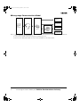
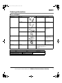
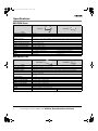
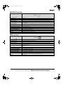
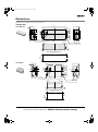
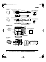
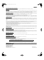
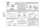
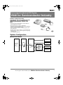
V640.fm Page 1 Wednesday, September 13, 2006 4:21 PM
Electromagnetic Inductive RFID System
V640 for Semiconductor Industry
Enables reading and writing
transponders for various Semiconductor
applications, such as FOUPs (FrontOpening Unified Pods), reticles, and
pods.
• Conforms to Carrier Reader/Writer-related SEMI standards; SEMI E99, E4, and E5.
• Antenna dimensions conform to SEMI E15.1.
• Reads/writes data embedded in a 32-mm Glass Multipage
Transponder (RI-TRP-DR2B/-WR2B).
• Noise measurement function for detecting proper placement of Antenna.
• Shielded antenna reduces influence of surrounding metal.
• Lineup incudes compact models designed for long-range
communications.
• CE marking/FCC approvals
System Configuration
■ Standard Models
ID Tag
CIDRW Head
Amplifier Unit
RS-232C host device
via dedicated 1:1
protocol
RS-232C host device
via ASCII protocol
RI-TRP-DR2B
RI-TRP-WR2B
(32-mm Glass
Transponder)
CIDRW Controller
Texas
Instruments
V640-HS61
RS-232C host device
via SECS I/II protocol
V640-HAM11-V2
V700-L22
RS-485 host device
via ASCII protocol
Electromagnetic Inductive RFID System
V640 for Semiconductor Industry
1
V640.fm Page 2 Wednesday, September 13, 2006 4:21 PM
■ Long-range Communications Model
ID Tag
CIDRW Head
RS-232C host device
via dedicated 1:1
protocol
Amplifier Unit
RS-232C host device
via ASCII protocol
RI-TRP-DR2B
RI-TRP-WR2B
(32-mm Glass
Transponder)
CIDRW Controller
Texas
Instruments
RS-232C host device
via SECS I/II protocol
V640-HS62
V640-HAM12
V700-L22
RS-485 host device
via ASCII protocol
Note: 1. Use of the V700-L11 ID Link Unit enables the Amplifier Unit to be removed/installed while the CIDRW System remains turned ON in the
event of a malfunction or during maintenance.
2. Use the V700-L22 CIDRW Controller when using SECS communications protocol.
3. Refer to the User’s Manual (V640-HAM11-V2: Cat. No. Z167; V640-HAM12: Cat. No. Z218) for details.
2
Electromagnetic Inductive RFID System V640
for Semiconductor Industry
V640.fm Page 3 Wednesday, September 13, 2006 4:21 PM
Ordering Information
■ List of Models
Name
Model
Specifications/Design
V640-HS61
50 × 30 × 12 mm (including 2-meter cable
mounting plate)
V600-HS62
65 × 30 × 12 mm (including 1.9-meter cable
mounting plate)
V640-HAM11-V2
80 × 185 × 43 mm
V640-HAM12
80 × 125 × 43 mm
CIDRW Controller
V700-L22
150 × 167 × 28 mm
24 VDC
RS-232C interface
(Compatible with SECS I/II
protocol.)
ID Link Unit
V700-L11
110 × 65 × 64 mm
24 VDC
RS-232C interface
RS-485 interface
Accessories
V640-A90
Connector accessories for the V640 Amplifier Unit
Power Supply Connector (1)
Power Supply Connector Pins (3)
RS-485 Port Connector (1)
(See Note.)
CIDRW Head
Amplifier Unit
RS-232C interface
RS-485 interface
24 VDC
Note: V640-A90 includes all of these accessories as a set. To purchase individual accessories, contact the manufacturers below directly.
To Purchase Individual Accessories
Name
Power Supply Connector
Model
1-178288-3
Power Supply Connector Pins
175217-3
RS-485 Port Connector
MSTB2.5/2-STF-5.08
Electromagnetic Inductive RFID System
Manufacturer
Tyco Electronics
Phoenix Contact Inc.
V640 for Semiconductor Industry
3
V640.fm Page 4 Wednesday, September 13, 2006 4:21 PM
Specifications
■ CIDRW Head
V640-HS62
V640-HS61
Item
Transmission frequency
134 kHz
Insulation resistance
20 MΩ min. (at 100 VDC) between the connector terminals and the case
Dielectric strength
1,000 VAC (50/60 Hz, 1 minute) between the connector terminals and the case (leakage current: 5 mA
max.)
Vibration resistance
10 to 150 Hz, 0.20-mm double amplitude, 15-m/s2 acceleration with 10 sweeps of 8 min each in X, Y, and
Z directions
Shock resistance
150-m/s2 acceleration for 3 times each in X, Y, and Z directions (18 times in total)
Ambient operating temperature
0 to 40°C (with no icing)
Ambient operating humidity
35% to 85% (with no condensation)
Ambient storage temperature
−15 to 65°C (with no icing)
Ambient storage humidity
35% to 85% (with no condensation)
Degree of protection
IEC60529: IP20
Cable
2-m (3-mm dia.) coaxial cable
Case
ABS/epoxy resin, stainless-steel mounting fixture
Weight
Approx. 70 g
1.9-m (3-mm dia.) coaxial cable
Approx. 100 g
■ Amplifier Unit
V640-HAM12
V640-HAM11-V2
Item
Host interface
RS-232C (via dedicated 1:1 protocol or 1:N protocol) or RS-485
Power supply voltage
24 VDC (max. fluctuation 20.4 to 26.4 VDC)
Power consumption
3 W max.
Insulation resistance
20 MΩ min. (at 100 VDC) between the power supply terminals and the frame ground terminal
Dielectric strength
1,000 VAC (50/60 Hz, 1 minute) between the power supply terminals and the frame ground terminal (leakage current: 5 mA max.)
Vibration resistance
10 to 150 Hz, 0.20-mm double amplitude, 15-m/s2 acceleration with 10 sweeps of 8 min each in X, Y, and
Z directions
Shock resistance
150-m/s2 acceleration for 3 times each in X, Y, and Z directions (18 times in total)
Ambient operating temperature
0 to 40°C (with no icing)
Ambient operating humidity
35% to 85% (with no condensation)
Ambient storage temperature
−15 to 65°C (with no icing)
Ambient storage humidity
35% to 85% (with no condensation)
Degree of protection
IEC60529: IP20
Case
SECC (coated)
Ground
Ground at a resistance of less than 100 Ω.
Weight
Approx. 500 g
4
Electromagnetic Inductive RFID System V640
Approx. 400 g
for Semiconductor Industry
V640.fm Page 5 Wednesday, September 13, 2006 4:21 PM
■ CIDRW Controller
V700-L22
Item
Host interface
RS-232C
Power supply voltage
24 VDC (max. fluctuation 20.4 to 26.4 VDC)
Power consumption
150 mW max.
Insulation resistance
50 MΩ min. (at 500 VDC) between the power supply terminals and the frame ground terminal
Dielectric strength
500 VAC (50/60 Hz, 1 minute) between the power supply terminals and the ground terminal (leakage current: 3.5 mA max.)
Vibration resistance
10 to 150 Hz, 0.20-mm double amplitude, 15-m/s2 acceleration with 10 sweeps of 8 min each in X, Y, and
Z directions
Shock resistance
150-m/s2 acceleration for 3 times each in X, Y, and Z directions (18 times in total)
Ambient operating temperature
0 to 40°C (with no icing)
Ambient operating humidity
10% to 85% (with no condensation)
Ambient storage temperature
−15 to 65°C (with no icing)
Ambient storage humidity
10% to 95% (with no condensation)
Degree of protection
IEC60529: IP20
Ground
Ground at a resistance of less than 100 Ω.
Weight
Approx. 580 g
■ ID Link Unit
V700-L11
Item
Host interface
RS-232C or RS-485
Power supply voltage
24 VDC (max. fluctuation 20.4 to 26.4 VDC)
Power consumption
10 W max.
Insulation resistance
50 MΩ min. (at 500 VDC) between the power supply terminals and the frame ground terminal
Dielectric strength
1,000 VAC (50/60 Hz, 1 minute) between the power supply terminals and the frame ground terminal (leakage current: 5 mA max.)
Vibration resistance
10 to 150 Hz, 0.20-mm double amplitude, 15-m/s2 acceleration with 10 sweeps of 8 min each in X, Y, and
Z directions
Shock resistance
150-m/s2 acceleration for 3 times each in X, Y, and Z directions (18 times in total)
Ambient operating temperature
0 to 40°C (with no icing)
Ambient operating humidity
35% to 85% (with no condensation)
Ambient storage temperature
−15 to 50°C (with no icing)
Ambient storage humidity
35% to 85% (with no condensation)
Degree of protection
IEC60529: IP20
Ground
Ground at a resistance of less than 100 Ω. If grounding is not performed properly, transmission specifications may be adversely affected by the surrounding environment.
Weight
Approx. 200 g
Electromagnetic Inductive RFID System
V640 for Semiconductor Industry
5
V640.fm Page 6 Wednesday, September 13, 2006 4:21 PM
Applicable SEMI Standards
■ CIDRW System Conforming to SEMI Standards
CIDRW System Conforming to SEMI Standards
V700-L22 CIDRW Controller
Host device
V640-HAM1@ Amplifier Unit
V640-HS6@ CIDRW Head
ID Tag*
(Texas Instruments)
SECS I/II
RS-232C
RS-232C
The Carrier ID Reader Writer (CIDRW) System is an RFID system that conforms to SEMI standards. The V700-L22 CIDRW Controller, the V640HAM1@ Amplifier Unit, the V640-HS6@ CIDRW Head, and a Texas Instruments ID Tag can be used to configure a Carrier ID Reader Writer (CIDRW) System that conforms to the following standards:
• SEMI E99 CARRIER ID READER/WRITER FUNCTIONAL STANDARD
• SEMI E5 EQUIPMENT COMMUNICATIONS STANDARD 2 MESSAGE CONTENT (SECS-II)
• SEMI E4 EQUIPMENT COMMUNICATIONS STANDARD 1 MESSAGE TRANSFER (SEC- I)
Note: SEMI: Semiconductor Equipment and Materials International (Refer to SEMI for standards information. (SEMI URL: http//:www.semi.org/))
SECS: SEMI Equipment Communications Standard
Refer to the User’s Manual (V640-HAM11-V2: Cat. No. Z167; V640-HAM12: Cat. No. Z218) for details.
V700-L22 conforms to SEMI E99-0303 (issued in March 2003).
* The following table lists the ID Tags (manufactured by Texas Instruments) that can be read/written by the V640 RFID System.
Amplifier Unit
CIDRW Head
V640-HAM11-V2
V640-HS61
V640-HAM12
V640-HS62
6
ID Tag (Texas
Instruments)
RI-TRP-DR2B
RI-TRP-WR2B
Electromagnetic Inductive RFID System V640
for Semiconductor Industry
V640.fm Page 7 Wednesday, September 13, 2006 4:21 PM
Dimensions
Note: All units are in millimeters unless otherwise indicated.
Amplifier Unit
V640-HAM11-V2
(15.8)
(17.8)
(13)
(12)
(32.5)
43
185
160
(30.5)
6.8
6.8
6.8
0.6
2
(12)
46 56 80
(18.2)
55.5
Four operation
indicator lamps
175
DIP switch
(4.5)
(11.6)
Four, 4.5 dia. (mounting holes)
1
(1.5)
Mounting Hole Dimensions
175±0.5
46±0.5
4-M4
]
(30.5)
V640-HAM12
43
125
2
100
(15.8)
(17.8)
(13)
6.8
6.8
6.8
4.6
(12)
46 56 80
(12)
(32.5)
33.5
Four operation
indicator lamps
(16)
115
DIP switch
(4.5)
(11.6)
Four, 4.5 dia. (mounting holes)
1
(1.5)
Mounting Hole Dimensions
115±0.5
4-M4
Electromagnetic Inductive RFID System
46±0.5
V640 for Semiconductor Industry
7
V640.fm Page 8 Wednesday, September 13, 2006 4:21 PM
CIDRW Head
V640-HS61
Four, 3.5 dia. (mounting holes)
9
Antenna center
3.0-dia. coaxial cable,
standard length 2 m
Connector
Mounting Hole Dimensions
Antenna center
4-M3 or 3.5 dia.
30 20 1210
20±0.2
21
29.2
50
9
21±0.2
12
4
V640-HS62
Four, 3.5 dia. (mounting holes)
3.011-dia. coaxial cable, length 1.9 m
9 Antenna center
Connector
Mounting Hole Dimensions
4-M3 or 3.5 dia.
30 20 12 10
Antenna center
28 max.
21
39.2
65
20±0.2
Ferrite core
49
12
14.5 20.5 max.
9
21±0.2
4
CIDRW Controller
V700-L22
150
130
28
Mounting Hole Dimensions
Power lamp
130±0.2
4-M4
151 167
3
Operation
indicator
lamps
151±0.2
24
7
P6×3
30
Four, 4.5 dia. (mounting holes)
ID Link Unit
V700-L11
110
41.5
26.5
41.3
18.5 20.3
65
Mounting Hole Dimensions
16.7 10.7
35.2
5
4
8
Two, 4.5 dia.
4
Electromagnetic Inductive RFID System V640
55±0.2
2-M4 or 4.2 dia.
100±0.2
60
for Semiconductor Industry
V640.fm Page 9 Wednesday, September 13, 2006 4:21 PM
Electromagnetic Inductive RFID System
V640 for Semiconductor Industry
9
V640.fm Page 10 Wednesday, September 13, 2006 4:21 PM
10
Electromagnetic Inductive RFID System V640
for Semiconductor Industry
V640.fm Page 11 Wednesday, September 13, 2006 4:21 PM
Electromagnetic Inductive RFID System
V640 for Semiconductor Industry
11
V640.fm Page 12 Wednesday, September 13, 2006 4:21 PM
READ AND UNDERSTAND THIS DOCUMENT
Please read and understand this document before using the products. Please consult your OMRON representative if you have any questions or comments.
WARRANTY
OMRON’s exclusive warranty is that the products are free from defects in materials and workmanship for a period of one year (or other period if specified) from date of sale by
OMRON.
OMRON MAKES NO WARRANTY OR REPRESENTATION, EXPRESS OR IMPLIED, REGARDING NON-INFRINGEMENT, MERCHANTABILITY, OR FITNESS FOR
PARTICULAR PURPOSE OF THE PRODUCTS. ANY BUYER OR USER ACKNOWLEDGES THAT THE BUYER OR USER ALONE HAS DETERMINED THAT THE PRODUCTS
WILL SUITABLY MEET THE REQUIREMENTS OF THEIR INTENDED USE. OMRON DISCLAIMS ALL OTHER WARRANTIES, EXPRESS OR IMPLIED.
LIMITATIONS OF LIABILITY
OMRON SHALL NOT BE RESPONSIBLE FOR SPECIAL, INDIRECT, OR CONSEQUENTIAL DAMAGES, LOSS OF PROFITS OR COMMERCIAL LOSS IN ANY WAY
CONNECTED WITH THE PRODUCTS, WHETHER SUCH CLAIM IS BASED ON CONTRACT, WARRANTY, NEGLIGENCE, OR STRICT LIABILITY.
In no event shall responsibility of OMRON for any act exceed the individual price of the product on which liability is asserted.
IN NO EVENT SHALL OMRON BE RESPONSIBLE FOR WARRANTY, REPAIR, OR OTHER CLAIMS REGARDING THE PRODUCTS UNLESS OMRON’S ANALYSIS
CONFIRMS THAT THE PRODUCTS WERE PROPERLY HANDLED, STORED, INSTALLED, AND MAINTAINED AND NOT SUBJECT TO CONTAMINATION, ABUSE, MISUSE,
OR INAPPROPRIATE MODIFICATION OR REPAIR.
SUITABILITY FOR USE
THE PRODUCTS CONTAINED IN THIS DOCUMENT ARE NOT SAFETY RATED. THEY ARE NOT DESIGNED OR RATED FOR ENSURING SAFETY OF PERSONS, AND
SHOULD NOT BE RELIED UPON AS A SAFETY COMPONENT OR PROTECTIVE DEVICE FOR SUCH PURPOSES. Please refer to separate catalogs for OMRON's safety rated
products.
OMRON shall not be responsible for conformity with any standards, codes, or regulations that apply to the combination of products in the customer’s application or use of the
product.
At the customer’s request, OMRON will provide applicable third party certification documents identifying ratings and limitations of use that apply to the products. This information by
itself is not sufficient for a complete determination of the suitability of the products in combination with the end product, machine, system, or other application or use.
The following are some examples of applications for which particular attention must be given. This is not intended to be an exhaustive list of all possible uses of the products, nor is
it intended to imply that the uses listed may be suitable for the products:
• Outdoor use, uses involving potential chemical contamination or electrical interference, or conditions or uses not described in this document.
• Nuclear energy control systems, combustion systems, railroad systems, aviation systems, medical equipment, amusement machines, vehicles, safety equipment, and
installations subject to separate industry or government regulations.
• Systems, machines, and equipment that could present a risk to life or property.
Please know and observe all prohibitions of use applicable to the products.
NEVER USE THE PRODUCTS FOR AN APPLICATION INVOLVING SERIOUS RISK TO LIFE OR PROPERTY WITHOUT ENSURING THAT THE SYSTEM AS A WHOLE HAS
BEEN DESIGNED TO ADDRESS THE RISKS, AND THAT THE OMRON PRODUCT IS PROPERLY RATED AND INSTALLED FOR THE INTENDED USE WITHIN THE OVERALL
EQUIPMENT OR SYSTEM.
PERFORMANCE DATA
Performance data given in this document is provided as a guide for the user in determining suitability and does not constitute a warranty. It may represent the result of OMRON’s
test conditions, and the users must correlate it to actual application requirements. Actual performance is subject to the OMRON Warranty and Limitations of Liability.
CHANGE IN SPECIFICATIONS
Product specifications and accessories may be changed at any time based on improvements and other reasons.
It is our practice to change model numbers when published ratings or features are changed, or when significant construction changes are made. However, some specifications of
the product may be changed without any notice. When in doubt, special model numbers may be assigned to fix or establish key specifications for your application on your request.
Please consult with your OMRON representative at any time to confirm actual specifications of purchased products.
DIMENSIONS AND WEIGHTS
Dimensions and weights are nominal and are not to be used for manufacturing purposes, even when tolerances are shown.
ERRORS AND OMISSIONS
The information in this document has been carefully checked and is believed to be accurate; however, no responsibility is assumed for clerical, typographical, or proofreading
errors, or omissions.
PROGRAMMABLE PRODUCTS
OMRON shall not be responsible for the user’s programming of a programmable product, or any consequence thereof.
COPYRIGHT AND COPY PERMISSION
This document shall not be copied for sales or promotions without permission.
This document is protected by copyright and is intended solely for use in conjunction with the product. Please notify us before copying or reproducing this document in any manner,
for any other purpose. If copying or transmitting this document to another, please copy or transmit it in its entirety.
ALL DIMENSIONS SHOWN ARE IN MILLIMETERS.
To convert millimeters into inches, multiply by 0.03937. To convert grams into ounces, multiply by 0.03527.
Cat. No. Z191-E1-04
In the interest of product improvement, specifications are subject to change without notice.
OMRON Corporation
Industrial Automation Company
Sensing Devices Division H.Q.
Industrial Sensors Division
Shiokoji Horikawa, Shimogyo-ku,
Kyoto, 600-8530 Japan
Tel: (81)75-344-7022/Fax: (81)75-344-7107
Printed in Japan
0906-0.3M (1103) (M)