1
University of Ljubljana
Faculty of Electrical Engineering
Laboratory of Photovoltaics and Optoelectronics
Datalogger DL844 User’s manual
Draft, April 2010
Introduction
The datalogger can read up to 8 analog voltages and 4 digital channels and store data
to an SD card or output it to RS-485 port. 4 current sources are provided to bias
sensors connected to the datalogger. Data can be time-stamped with internal batterybacked clock. The FAT formatted card can also be read from RS-485, (RS-232) or
USB port. Configuration can be stored on the card or transferred through RS-485.
Various supply options are available including internal rechargeable battery.
Specifications in this manual are preliminary and are subject to change without prior
notice.
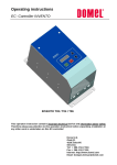
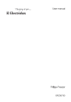
Local user interface
Buttons
RST
START
PWR
Holding this button at power on will reset RS-485 address to 53
(decimal) and clock to 2000-01-01 0:00:00. The button can be also
used to clear a run-time error, i.e. turn off error LED.
Pressing the button will start or stop logging process.
Pressing the button will power on/off the datalogger.
LEDs
PWR (green) Signals that the datalogger is powered. Blinks when it is running on
batteries and is solid when on external power.
BAT (yellow) Blinks when the main battery is low.
USB (red)
Lights when the datalogger is connected to USB an enumerated.
Logging process cannot be started when this LED is lit.
SAMP (green) Lights when sample is being taken.
LOG (yellow) Lights when logging is active or when data is transferred over USB.
ERR (red)
Signals error with one long blink and certain number of short blinks
(see table below). Blinking is continued while logging is active. In that
case blinking can be stopped by pressing the RST key.
At power on logging is not active. Logging can only be started when an SD card is
inserted and USB cable is not connected. When logging is started, configuration file
on the card will be parsed and logging will begin. Logging is normally stopped with
key or remote command, but will also be stopped when USB cable is plugged in and
USB enumerated, memory card is filled-up and battery is empty. Logging is also
stopped when the power button is pressed.
The datalogger will be automatically turned of when battery is empty. Note that when
the datalogger is connected to USB it is still powered from battery unless external
power is applied.
Blinks
1
2
3
4
5
6
7
Error
No memory card was detected.
The card is full.
Other card error.
The card is write-protected.
No configuration file was found.
Error parsing configuration file.
1-wire error. No sensor was found on one of specified channels or a
sensor can not be read.
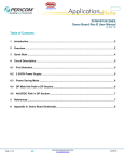
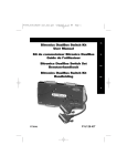
Connections
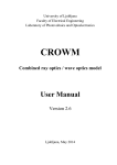
Front panel
Connection of measurement signals to the datalogger is accomplished by 3-pole
modular plug connectors. The pinouts of all connectors are visible from the image
above. G and GND stands for ground connection. Ground is common to all
connections, however, analog and digital ground should not be mixed.
5V, REF, GND
Power supply output. 5 V is filtered supply and present only when bias is present.
REF is reference voltage output and is not intended for supply of power hungry
external circuits. GND is analog ground.
ANALOG INPUTS
Inputs for analog signals. Input range depends upon configuration. Differential signals
should be defined, not floating. G is analog ground.
EXCITATION
These pins output constant current if voltage on them is within certain limits. G is
analog ground.
DIGITAL I/O
These pins go to CMOS 3.3 V logic through protection circuits. G is digital ground.
5V, 3V3, GND
Power supply output. 5 V is present only when bias is present. 3V3 is always present,
even when the datalogger is turned off. 5V output can be used as an enable signal to
draw higher current from 3V3 pin. G is digital ground.
RS-232
RS-232 interface has DTE pinout and can be used to monitor output data. Data will be
output in the same format as to the file.
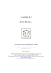
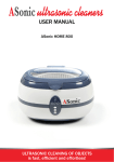
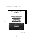
Back panel
DC in
These are connectors for external supply voltage. Both of the connectors are in
parallel. Ground is the same as for other connections including front panel
connections.
BAT
This connector is intended for external battery and is connected in parallel to internal
battery. It is output of power supply that receives power from DC-in connectors. All
the circuitry is powered from this supply.
RS485
Connection for RS-485 bus. Using internal jumpers termination and pull-up resistors
can be enabled. Datalogger is a slave in master-slave configuration.
USB
USB B-type receptacle for connection to a USB host. The datalogger acts as a
Standard Mass Storage Device to access the Secure Digital card.
LAN
8P8C socket for connection to 100BASE-TX or 10BASE-T network.
Secure Digital
Socket for a Secure Digital memory card. The card should be inserted face-up, that is
with pins facing down.
Configuration file syntax
Configuration file must be named config.txt and is loaded and interpreted at beginning
of logging operation. Data will be output to a new file named log_NNNN.txt. The 4digit number will be one more than the highest already existing number. If the highest
existing number is 9999, search for free number will begin with 0001. If none is
found, data will be appended to file named output.txt. Each sample is in new line,
whereas channels are separated with semicolon. Buffered data is flushed to the card
every 10 minutes to prevent loss of data.
General configuration
Each parameter is given in a separate line.
PER <value> [min | hr]
Sample period. Default value is 1 minute. Default unit is second.
Channel configuration
Each channel configuration is given in a separate line. Order of parameters is not
important, however FRMT must be the last one.
[<function>@] <channel> [GAIN <gain>] [BUFF (ON | OFF)] [MATH <k> [<n>]]
[FRMT <format string>]
functions
VOLT
BIT
PTx
TCK
TEMP
TIME
DATE
CLCK
VBAT
VEXT
IEXT
channel
Syntax:
type:
Measure voltage. Default for analog channels.
Bit(s) value. Default for digital channels.
Convert value for Platinum RTDs. Input value of 1 V represents 0 °C.
Algorithm (3rd/4th order polynomial) is applied after math.
Convert value for K-type thermocouple. Input values are in volts.
Algorithm (9th/8th order polynomial) is applied after math.
Measure temperature of 1-wire sensors on a digital channel.
Time in the format hh:mm:ss.
Date in the ISO format YYYY-MM-DD.
Time and date. Default for RTC channel.
Internal battery voltage. Default for SYS channel.
External supply voltage.
External supply voltage.
<type><number>
A – analog, D – digital, RTC – real time clock, SYS – system
variables.
number:
number from 0 to number of channels-1, omitted for RTC and SYS
channel.
E.g.: A0, A3, D0
For differential measurements: <+channel>-<-channel>, e.g. A1-A0.
For byte value: <highest bit>-<lowest bit>, e.g. D3-D0
GAIN
Sets PGA gain. Supported values are 1, 2, 4, 8, 16, 32 and 64. Default and
recommended is 1. Gain is taken into account for value output, i.e. no additional
scaling is necessary.
BUFF
Turn buffer for analog channels on or off. Default and recommended is on.
MATH
Applies 1st order polynomial to measured value, i.e. scaling and offset addition. It is
applied before algorithm that gives physical value (e.g. Platinum RTD).
FRMT
Define output format string. FRMT must be the last parameter and ends at the end of
the line. C language syntax is used. Integer value is given for pure digital channels
(%d, %o, %x or %X type), whereas float value is used for analog channels,
temperatures and system channel (%f, %e, %E, %g or %G type). Useful to reduce
precision and to give units to results. Default is %d for integer values and %f for
analog values. The parameter is completely ignored for RTC channel. Maximum
length is 15 characters.
Example
Configuration file (config.txt):
PER 5
TIME@RTC
A0
A1 FRMT %.2f
A3-A2 FRMT %.2f
PTx@A4 MATH 10 0
TEMP@D3
D2-D0
Sample every 5 seconds. Make 7 measurements: time, 2 single ended voltages, 1
differential voltage, RTD temperature, temperature of 1-wire sensors, 3-bit value.
Output file (output.txt):
Starting datalogger, 2 channels, configuration:
PER 5
TIME@RTC
A0
A1 FRMT %.2f
A3-A2 FRMT %.2f
PTx@A4 MATH 10.000000 0.000000
TEMP@D3
D2-D0
1-wire sensors on D3:
28C358110100006F
28954B0202000095
Log started at: 16:18:00 2009-08-18
Log stopped at: 16:18:57 2009-08-18
16:18:45; 3.763444; 1.23; 0.45; 45; 47; 46; 5
16:18:50; 3.763445; 1.23; 0.45; 45; 47; 46; 5
16:18:55; 3.763442; 1.23; 0.45; 45; 47; 46; 5
Interpretation:
First sample was taken at 2009-08-18 16:18:00. Logging process was manually
stopped at 2009-08-18 16:18:57. If logging is stopped because of full card or empty
battery, this info (“(Card)” or “(Bat) ”) is written at the end of Log stopped line. If this
line is absent (filled with spaces), it is indication that logging ended in an uncontrolled
manner (e.g. the card was removed or system power was lost).
Voltage of 3.76344 V is present between A0 and ground.
Voltage of 1.23 V is present between A1 and ground.
Voltage of 0.45 V is present between A3 and A2.
Platinum sensor has temperature of 45 °C (math is for PT100 and excitation current of
1 mA or PT1000 and excitation current of 0.1 mA).
Two 1-wire sensors with addresses 28C358110100006F and 28954B0202000095
were detected on D3 and have temperatures of 47 °C and 46 °C.
Pins D2 and D0 are at logical one, while D1 is at logical zero.
Real time clock setup
Internal RTC of the datalogger can be set by writing the desired date and time to a file
named set_clk.txt. The file is parsed when START/STOP key is pressed and clock set
if deletion of the file is successful. In that case logging will not start. Date and time
must be in the format: YYYY-MM-DD HH:MM:SS. Additional internal battery is
provided for independent power of RTC.
RS-485 commands
Only one command is allowed in a packet. Maximum length of user data in a packet is
currently 248 bytes. If the command is not a query, nothing is returned.
*IDN?
Return product identification string. The string include last compile date.
*CLS
Clears error queue.
*ADR <address>
*ADR?
Sets or reads RS-485 device address. Address set will be stored to FLASH memory
and taken into account on next system start-up.
LOG:RUN ON/OFF
LOG:RUN?
Start or stop logging process or query state. Configuration is always taken from
config.txt file and results are output to output file.
CHAN <conf>
CHAN?
Set or read channel configuration for RS-485 query only. The configuration is lost
after starting logging process. Syntax is the same as for config.txt file. ^ character can
be used instead of new lines. After logging is stopped, its configuration will be used
for RS-485 queries.
INIT
Start measuring with current configuration. Nothing is returned. This command can
only be used when logging is not active.
MEAS?
Start measuring with current configuration and return result. The format is the same as
in output.txt file, but only one sample is measured and returned. This command can
only be used when logging is not active.
READ?
Read last sample taken. This command can be used whenever the sample is ready, i.e.
after taking the first sample during logging process or after performing measurement
with INIT or MEAS? commands.
MMEM:
Subsystem for access to files on SD card. Only files in the root folder can be accessed.
Commands supported are :CAT?, :DATA, :DATA? and :DEL. Commands can also
be used during logging.
MMEM:CAT?
The CATalog command is query-only and returns information on the current contents
and state of the mass storage media. Sizes are in bytes. The returned format is:
<amount_of_storage_used>,<amount_of_storage_available>{,<file entry>}
Each <file entry> is a string in the form:
<file_name>,<file_type>,<file_size>
File type is always empty.
Large listings will span over multiple packets. In that case all packets but last will end
with comma, denoting another packet.
MMEM:DATA <file_name>,<data>
The command loads <data> into the file <file_name>. <data> is in 488.2 block
format. <file_name> is string data.
The query form is MMEMory:DATA? <file_name> with the response being the
associated <data> in block format.
Block format:
#<n><size><binary_data>
<size> is number of useful bytes in the block in decimal format. <n> is number of
characters in <size>.
Large files will span over multiple packets. When writing file, subsequent packets
will be assumed as part of the file until <size> bytes are transferred. There should be
pause of at least 10 ms between packets to allow data to be processed.
MMEM:DEL <file_name>
Deletes a file from the mass storage device.
SYST:ERR?
SYST:ERR:NEXT?
Both commands retrieve an error from a first-in-first-out (FIFO) queue. If more than
19 errors have occurred, the last error stored in the queue is replaced with -350,”Too
many errors”. If no errors have occurred, the datalogger responds with +0,”No
errors”. Error queue is cleared on power on and after *CLS command.
Error codes:
0 No error
Error queue is empty.
-100 Command error
Command was not recognized by the datalogger.
-109 Missing parameter
Fewer parameters were received than required for the header.
-113 Undefined header
A command was received that is not valid for the datalogger. Check
spelling.
-150 String data error
A string parameter (filename in MMEM:DATA command) was not
correctly received. Check that the filename is surrounded with double
quotes.
-221 Settings conflict
Command cannot be currently executed. Sampling cannot be triggered
(MEAS? or INIT command) and configuration cannot be changed when
logging process is active. Use READ? command to retrieve the last
sample. Memory card cannot be accessed when USB connection is active.
-250 Mass storage error
There is a problem accessing memory card. Check that the required file
exists and that the card is properly formatted and inserted.
-285 Program syntax error
There is a syntax error in configuration given with CHAN command.
-350 Queue overflow
The queue is full because more than 19 errors occurred.
RS-485 protocol
Protocol on top of RS-485 interface is a multi-drop master-slave protocol. Data is
transferred in addressed packets. Address of master must be 0. The datalogger will
respond to requests and cannot be programmed to continuously send data. Large data
blocks (MMEM catalog and files) will span multiple packets.
Data rate is 250 kb/s with standard serial formatting, i.e. 8N1. The bus can be
internally terminated with 120 Ω by installing jumper JP107. Jumpers JP105 and
JP106 enable pull-up/pull-down resistors to guarantee idle state. These resistors are
disabled when datalogger is turned off to save power.
If more than 1 datalogger is used in a system, unique address much be set to each of
them.
Byte
0
1
2
3
4…n+4
n+5
n+6
n+7
Meaning
STX
destination
source
length
data
CRC MSB
CRC LSB
ETX
Description
Start delimiter (0x55)
Destination address
Source address
Length of payload – n
Payload, max 248 bytes
CRC-16-IBM checksum
polynomial: 0x8005
End delimiter (0xAA)
Specifications
Analog inputs
Number
8 single ended / 4 differential
any combination possible
Max scanning rate
1 S/s
Resolution
24 bits
Absolute input range*1
0…3V
Input protection
-10 … 10 V
Differential input range
±5 V / PGA
PGA gains
1, 2, 4, 8, 16, 32, 64
Input impedance
80 MΩ
Error (gain=1)*2
± (0.01 % + 15 µV)
Evaluation possible
Platinum RTDs and K-type
thermocouples
*1 – Higher input ranges (in different combinations) are available on request.
Current source outputs
Number
4
Current*3
1 mA
Accuracy*2
±0.25 %
Voltage range
-40 … 3.8 V
*2 – Reference voltage tolerance should be added for absolute
measurements.
*3 – Other values (in different combinations) are available on request.
Digital inputs
Number
Low level
High level
Input protection
Input resistance
Protocol supported
4
0 … 0.8 V
2…5V
-4 … 8.5 V
50 kΩ typical
1-wire temperature sensors
Supply and reference outputs
+5V accuracy
Maximal current
+3.3V accuracy
Maximal current
Ref. voltage accuracy
Temp. coefficient
Maximal current
±2.5 % (linear regulation)
100 mA
±3 % (switch mode regulation)
500 mA
±0.05 %, ±0.01 % on request
10 ppm/°C
9 mA
Data storage
Medium
File system
Data format
Secure Digital (SD) card (up to 2 GB)
FAT12, FAT16 or FAT32
Comma Separated Value (CSV)
with user defined formatting
Interfaces
USB
Standard
Class
USB 1.1
Mass Storage Class access to SD card
RS-232 (optional)
Connector
Lines
DB9 DTE (male)
TxD, RxD, RTS, CTS, DSR, DTR
RS-485
Operation
Speed
multi-drop device
250 kb/s
Power supply
External voltage
Power (external supply)
10 … 60 V
5 W maximal (battery charging)
0.3 W typical
0.05 W in sleep mode
Battery (optional)
Pb 3-cell (6 V, 1.2 Ah)*4 or
Li-ion 2-cell (7.4 V, 2.2 Ah)
- connector for external battery
RTC battery
Lithium cell CR2032
USB supply
100 mA typical (for SD card access only)
Options
- different voltage range
- MPP tracking (for PV module power supply)
- USB battery charging
*4 – Requires higher enclosure.
Dimensions
Width x Depth
Height
Weight
190 x 140 mm2
30 (50, 70) mm
320 g without battery
420 g with Li-ion battery
650 g with Pb battery
Designed by
University of Ljubljana
Faculty of Electrical Engineering
Tržaška cesta 25, 1000 Ljubljana, Slovenia
Laboratory of Photovoltaics and Optoelectronics
http://lpvo.fe.uni-lj.si
http://lpvo.fe.uni-lj.si/datalog/
Dr. Marko Topič
Head of LPVO
E-mail: marko.topic[at]fe.uni-lj.si
Phone: +386 1 4768 470
Dr. Boštjan Glažar
The designer
E-mail: bostjan.glazar[at]fe.uni-lj.si
Phone: +386 1 4768 723
Last update: April 2010