1
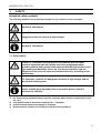
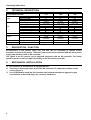
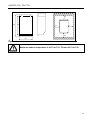
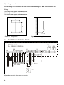
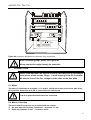
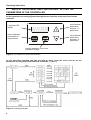
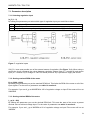
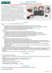
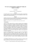
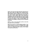
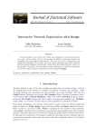
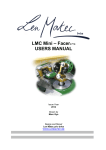
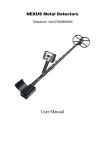
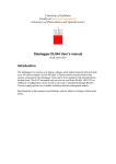
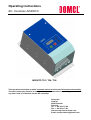
Operating instructions EC- Controller INVENTO INVENTO T03 / T04 / T06 This operation instruction contains important technical advice and information about safety. Therefore please pay attention to this operation instruction before unpacking, installation or any other work is undertaken on this EC-controller! Domel d.d. Otoki 21 4228 Železniki Slovenia Tel: + 386 4 5117 594 Fax: + 386 4 5117 591 Internet: http://www.domel.com Email: [email protected] Operating instruction Contence: 1. Side: Safety............................................................................................................................................. 3 1.1. Safety advice ............................................................................................................................. 3 2. Technical description............................................................................................................... 4 3. Description / Function .............................................................................................................. 4 4. Mechanical installation ............................................................................................................ 4 5. Electrical installation................................................................................................................ 6 6. Connection.................................................................................................................................... 7 6.1. Mains.......................................................................................................................................... 7 6.2. Motor connection...................................................................................................................... 7 7. Ways of adjustment and controlling / setting the parameters of the controller ................. 8 7.1. Parameter description .............................................................................................................. 9 7.1.1 Selecting regulation input .................................................................................................. 9 7.1.2. Setting maximal RPM of the motor ................................................................................... 9 7.1.3. Setting minimal RPM of the motor.................................................................................... 9 7.1.4. Setting fixed day RPM of the motor................................................................................ 10 7.1.5. Setting fixed night RPM of the motor ............................................................................. 10 7.1.6. Setting ramp up ................................................................................................................ 10 7.1.7. Setting ramp down ........................................................................................................... 10 7.1.8. Setting the RE 2 value...................................................................................................... 10 7.2 Setting of the parameters........................................................................................................ 11 7.3. Starting the operation............................................................................................................. 11 Note: for motor to start you must apply +15V(terminal 11) to RF terminal ! ...................... 11 7.4. Run mode ................................................................................................................................ 11 8. Other external conection terminals ............................................................................................. 11 8.1 Input Start – Stop (RF terminal) .......................................................................................... 11 8.2 Input direction of rotation (CW, CCW)................................................................................ 11 8.2 Input direction of rotation (CW, CCW)................................................................................ 12 8.3 Reset input............................................................................................................................ 12 8.4 Speed output – digital.......................................................................................................... 12 8.5 Operating relay RE1 (switch 25, 26, 27) ............................................................................. 12 8.6 Fault relay RE2 (switch 38, 39, 30) ...................................................................................... 12 9. parameter Setup table for motors and ventilators ..................................................................... 13 10. Security examinations before start-up ...................................................................................... 14 10.1. Security examinations before start-up................................................................................ 14 10.2. Before the first operation is to be guaranteed ................................................................... 14 10.3. Operation ............................................................................................................................... 14 11. Service, address of producer ................................................................................................ 15 12. Note.......................................................................................................................................... 15 2 INVENTO T03 / T04 / T06 1. SAFETY Industrial safety symbols The following symbols refer to particular dangers or give advice for save operation. Important, information Danger from electric current or high voltage! Important, information 1.1. Safety advice Domel EC- controllers are produced in accordance with the latest technical standards and our quality assurance programme which includes material and function tests ensures that the final product is of a high quality and durability. Never the less these controllers can be dangerous if they are not used and installed correctly, according to the instructions. EC-Controller could be life dangerous because of high voltage and its mechanical rotating parts. Before installing and operating this ec-controller please read this instructions carefully! the electrical and mechanical parts must be protected with protective components (cover, net, etc.), only qualified staff is allowed to install the EC – Controller, system documentation must always be available, system must be installed in accordance with the local regulations. 3 Operating instruction 2. TECHNICAL DESCRIPTION EC-Controller Invento Rated current [A] Output voltage [V] Output power [kW] Max. output power [kW] Output Input voltage [V AC] Frequency [Hz] Rated input power [kW] Rated input current [A] Max. Input power [kW] Max. Input current [A] Wire cross section [ mm2 ] Input Protective functions T06 3x4,5 3 x 400 2,2 2,7 3 x 400 V + 5% - 10 % 50 / 60 2,5 3 × 4,1 3,0 3 × 5,0 1,0 3x6,7 3 x 400 3,3 4,0 3 x 400 V + 5% - 10 % 50 / 60 3,7 3 × 6,2 4,5 3 × 7,5 1,5 o B x H x T (mm) Operating position o o o o o -10 C - +40 C Forced convection -10 C - +40 C Forced convection -10 C - +30 C Forced convection 146 x 300 x 167 146 x 300 x 167 146 x 300 x 167 Upright position Upright position Upright position Cooling Dimensions T04 3x3 3 x 400 1,5 1,8 3 x 400 V + 5% - 10 % 50 / 60 1,7 3 × 2,8 2,0 3 × 3,3 1,0 Over current protection, under voltage protection Ambient temperature Ambient T03 Table 1 Specifications 3. DESCRIPTION / FUNCTION EC-controllers of the Invento range T03, T04 and T06 are necessary to operate Domel brushless sensorless EC motors. These EC motors must not be operated with the direct power supply and therefore need an EC-controller. The speed of the EC motors can be adjusted steplessly with the EC-controller. The actual speed is shown on the four-digit LCD-display on the front of the controller. 4. 4 MECHANICAL INSTALLATION EC-Controller is mounted into an upright position, There has to be enough space around the EC-Controller for undisturbed airflow for the cooling (figure 1), It is not allowed to install the EC-Controller into polluted atmosphere (aggressive gas, concentration of dust and damp, fat, corrosive substance). INVENTO T03 / T04 / T06 167 100 300 255 50 50 100 146 Figure 1 dimension diagram and minimum distances Maximum ambient temperature is 40°C for T03, T04 and 30°C for T06 5 Operating instruction For the fitting of EC-Controller we need 4 holes in the wall, figure 2. Max. screw diameter is 5 mm. Fixing: Partly screw upper and lower screws, Hang up the EC-controller on the screws, Screw down upper and lower screws. 110 287 Figure 2 5. fixing holes Figure 3 removing the cover ELECTRICAL INSTALLATION EC- Controller 3~ 400 Volt / 50/60 Hz X5 RE1 X4 X6 X2 X3 DS M1 M2 M3 M4 M5 M6 PE L1 L2 L3 19 20 21 22 23 24 M1 PE 7 8 9 10 11 12 13 14 15 16 17 18 M3 M4 M5 M6 Poti 10 kΩ EC- Motor PE L1 L2 L3 - + 0 … 10V Figure 4a connection diagramm ec-controller 6 RE2 0 - 10 Volt Freigabe Enable 25 26 27 28 29 30 INVENTO T03 / T04 / T06 X2 X3 7 8 9 10 11 12 X4 M1 13 14 15 16 17 18 M2 M3 M4 M5 M6 25 26 27 28 29 30 X5 PE L1 L2 L3 X6 Figure 4b connection diagramm ec-controller / plug connection When connecting plugs please see Figure 4b. Wrong connection might destroy the controller. 6. CONNECTION Before initial operation we have to check up, that there are no mechanical parts (wires, female screws, filings…) in the housing of the EC-Controller We have to check if the line voltage suit the value on the data plate 6.1. Mains The mains is connected to terminals L1, L2 and L3, which are located on the lower part of the EC-controller. Protective earth PE is connected to an earth screw. First of all protective earth has to be connected. 6.2. Motor connection The motor and EC-controller are connected with two cables: Six wire cable for the motor connection – terminals 19 – 24, Earth wire diameter 10 mm2 - Protective earth. 7 Operating instruction 7. WAYS OF ADJUSTMENT AND CONTROLLING / SETTING THE PARAMETERS OF THE CONTROLLER All the parameters are easily adjusted through the user interface on the top of the Invento controller. move between parameters, increase of parameters 7 segment LED display start of operation, confirmation of the parameter move between parameters, decrease of parameters stop the operation, return from parameter change Figure 5: The outline of Invento user interface On the operating flowchart you can see how to move round the menu and set up the parameters by using keys START/ENTER, STOP/ESC, (+) and (-). Figure 6: operating flowchart 8 INVENTO T03 / T04 / T06 7.1. Parameter description 7.1.1 Selecting regulation input In_P (1…3) By setting this parameter you select which type of regulation input you would like to have. 1 2 3 Analog input - E Sensor input - PI Keyboard input – setup of speed by keys between operation or F_Rpm in Setup mode Figure 7: regulation inputs If IN_P=1 user must provide one of the external means of regulation (See Figure 7: A). When using a sensor the circuit compares the values between regulation voltage input (E – terminal 8) and sensor input (PI – terminal 14). A voltage of +24V DC/40mA (terminal 15) is provided to supply the sensor. 7.1.2. Setting maximal RPM of the motor H_rp (1000…6000) By setting this parameter you set the maximal RPM limit. This limits the RPM of the motor on all of the input signals. For the value of parameter see table1 in section 9. For example: if you set H_rp at 2000RPM at 10V of regulation voltage on input E the motor will run at 2000RPM. 7.1.3. Setting minimal RPM of the motor L_rp (0…600) By setting this parameter you set the minimal RPM limit. This sets the start of the motor at preset minimal value at minimal voltage input. For the value of parameter see table1 in section 9. For example: if you set L_rp at 300RPM at 0V of regulation voltage on input E the motor will run at 300RPM. 9 Operating instruction 7.1.4. Setting fixed day RPM of the motor F_rp (L_rp…H_rp) If you select IN_P=3 than you selected fixed day RPM. This means that the controller will regulate the RPM of the motor to match the selected F_rp value of the RPM. You can change this value during operation in run mode by pressing ENT button. You get displayed the previous set value and by pressing the UP or DOWN buttons you can change it. The value can be changed between previusely set value of L_rp and H_rp. By pressing ENT button you verify the new value, which will take immediate effect. If you don't want to change the value you can exit by pressing ESC button. 7.1.5. Setting fixed night RPM of the motor n_rp (L_rp…H_rp) If you select IN_P=3 than you selected fixed day value of the wanted RPM. But if you would want another preset value to take effect (so called night value), you apply 15V(terminal 11) to a DS input. This means that the controller will regulate the RPM of the motor to match the selected n_rp value of the RPM. You can change this value during operation while in run mode if 15V(terminal 11) is applied to DS. By pressing ENT button you get displayed the previous set value and by pressing the UP or DOWN buttons you can change it. The value can be changed between previously set value of L_rp and H_rp. By pressing ENT button you verify the new value, which will take immediate effect. If you don't want to change the value you can exit by pressing ESC button. 7.1.6. Setting ramp up r_up (1…9) Ramp up means the response of acceleration of the motor at positive change of regulation voltage. Selected value 1 means the fastest response while 9 is the slowest; it affects all regulation inputs selected by In_P (the foreseen minimal value for certain ventilator + motor set can be selected from the table) For the value of parameter see table1 in section 9. 7.1.7. Setting ramp down r_dn (1…9) Ramp down means the response of slowing down the motor at negative change of regulation voltage. Selected value 1 is the fastest response while 9 is the slowest; it affects all regulation inputs selected by In_P (the foreseen minimal value for certain ventilator + motor set can be selected from the table) For the value of parameter see table1 in section 9. 7.1.8. Setting the r_2 value r_2 (200…H_rp) This parameter is not used. 10 INVENTO T03 / T04 / T06 7.2 Setting of the parameters When the load voltage is applied to the controller it immediately starts by setting in the run mode. You have cca. 3 seconds to stop operation before it begins by pressing ESC button! A blinking S_UP sign appears, that means setup mode. To enter the setup mode press ENT button and hold it until S_UP stops blinking and In_P occurs. By pressing buttons UP and DOWN you can select the parameter you want to change and then press ENT and hold it until parameter preset value occurs. Than you can change the value by pressing buttons UP and DOWN. You verify the value by pressing ENT or you can exit without changing the parameter with ESC button. This applies to all the parameters in S_UP mode. 7.3. Starting the operation When all the parameters are set, you can exit the setup mode by pressing ESC. A blinking run sign appears. By pressing the ENT until run sign stops blinking you verify the operation of electronics. You have cca. 3 seconds to stop operation before it begins. When the load voltage is applied to the controller it immediately starts by setting in the run mode. You have cca. 3 seconds to stop operation before it begins. Note: you must apply +15V(terminal 11) to RF (terminal 10) to start the motor (fan) ! 7.4. Run mode You can start the operation by turning on the line voltage and the electronics will set itself in the run mode. You can also start the operation by exiting from the setup mode and pressing ENT button. Led display displays the value of the RPM of the motor. The motor will operate according to the type of the regulation selected in S_UP mode in IN_P parameter setup. You can stop its operation by pressing ESC button, which will put you in setup mode. If in IN_P mode you selected parameter 3 (keyboard selected wanted value of RPM) you can change this value during operation in run mode by pressing ENT button. You get displayed the previous set value and by pressing the UP or DOWN buttons you can change it. By pressing ENT button you verify the new value, which will take immediate effect. If you don't want to change the value you can exit by pressing ESC button. 8. OTHER EXTERNAL CONECTION TERMINALS 8.1 Input Start – Stop (RF terminal) RF input is designed for stopping and starting the drive while connected to the mains. It can be done by just connecting RF terminal with +15V(terminal 11) terminal with an wire or via external switch. Note: for the motor to start you must apply +15V(terminal 11) to RF (terminal 10)! 11 Operating instruction 8.2 Input direction of rotation (CW, CCW) This can be made by connecting +15V(terminal 11) to the terminal 16. The motor has to stand still when changing the direction of rotation! 8.3 Reset input The controller has an over-current protection. This protection activates if there is short circuit between motor wires, to earth or if a power transistor fails. By connecting the terminal R (12) with +15V (terminal 11) for about one second over-current protection can be reset and if controller is not damaged it will start to operate. If not – please consult the supplier! 8.4 Speed output – digital Imax=20mA f The pulse frequency at the terminal DD (17) is proportional to the speed of the motor. Output is "open collector" type, max. current 20mA, voltage 24V(fig. xx) n=fx2 n – rpm f - frequency of pulses Example: measured frequency at the terminal DD is 1400Hz. The speed of the motor is 1400 x 2 = 2800 rpm 8.5 Operating relay RE1 (terminal 25, 26, 27) Until the RF signal is set (0V on RF) the relay contacts are closed between 25 and 27. If RF is set (+15V) the relay contacts 25 and 26 are closed. If a fault signal has occurred on controller during the operation the RE1 switches the contact back to 25 and 27 and Err sign would be blinking on LED display. 8.6 Fault relay RE2 (terminal 28, 29, 30) The controller is monitoring +15V supply, DC link voltage and over current protection. If the controller is ready to operate, contacts 28 and 29 are closed. If fault occurs ( +15V supply to low, or DC link voltage to low, or over current protection activated) contacts 28 and 30 are closed and Err signal is blinking on LED display. 12 INVENTO T03 / T04 / T06 9. PARAMETER SETUP TABLE FOR MOTORS AND VENTILATORS Ventilator Motor H_rp (1000-6000) L_rp (0-600) R_up (1-9) * R_dn (1-9) * * It is sugested that R_up and R_dn are the same value Table 1: table of parameters for specific aplication 13 Operating instruction 10. SECURITY EXAMINATIONS BEFORE START-UP 10.1. Security examinations before start-up the adjustments according to the operating manual (chapter 6) and fan data plate are made correct, that the mains voltage corresponds to the data on the ec- controller data plate, that the controller is installed in accordance with assembly instruction (chapter 3), that the drive is not energized (main switches out), that the motor is moveable freely by hand, that the connecting terminals by the mains and motor connection are well tightened. 10.2. Before the first operation is to be guaranteed The value of parameter H_rp must not be higher than max allowed rpm of the fan. Input RF deactivate. If there is switch between RF and +15V is present, this is to be opened for the first operating. That the set value is 0V DC when In_p is 1 or 2. That F-rp is set to low speed when In_p is 3 main switch on. 10.3. Operation Three to four seconds after connecting the ec- controller to the mains the controller is ready to operate. 14 Close the switch at RF and +15V (terminal 10 and 11) Slowly increase set value ( terminal 8 ) when In_p is 1 or 2. The motor (fan) starts turning. Check, if the fan is rotating in the right direction. When In_p is 3 the motor (fan) will accelerate to the set value of the parameter F_rp. Check, if the fan is rotating in the right direction. If the direction of rotation is right, you can increase the speed. If the direction of rotation is wrong, you have to stop the drive and change the direction of rotation. ( at zero speed only) Repeat the starting procedure. INVENTO T03 / T04 / T06 11. SERVICE, ADDRESS OF PRODUCER Domel-products are subject to steady quality controls and are in accordance to valid regulations. In case you have any questions with regard to our products please contact either your constructor of your air handling unit or directly to one of our distributors: Domel d.d. Otoki 21 4228 Železniki Slovenia Tel: + 386 4 5117 594 Fax: + 386 4 5117 591 Internet: http://www.domel.com Email: [email protected] 12. NOTE 15