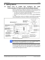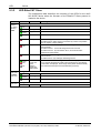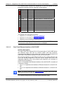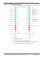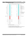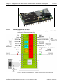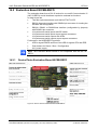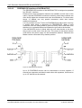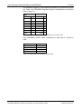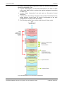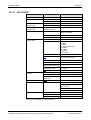
1
User Manual and Design Guide netIC DIL-32 Communication IC for Real Time Ethernet and Fieldbus Hilscher Gesellschaft für Systemautomation mbH www.hilscher.com DOC080601UM25EN | Revision 25 | English | 2014-05 | Released | Public Introduction 2/241 Table of Contents 1 INTRODUCTION.........................................................................................................7 1.1 1.2 Obligation to read and understand the Manual...........................................................7 About the User Manual and Design Guide .................................................................7 1.2.1 1.2.2 1.2.3 1.3 Contents of the Product DVD ...................................................................................12 1.3.1 1.3.2 1.4 Copyright ............................................................................................................15 Important Notes ..................................................................................................15 Exclusion of Liability ...........................................................................................16 Warranty .............................................................................................................16 Export Regulations .............................................................................................16 Registered Trademarks......................................................................................17 SAFETY ....................................................................................................................18 2.1 2.2 General Note ............................................................................................................18 Intended Use ............................................................................................................18 2.2.1 2.2.2 2.2.3 2.3 2.4 2.5 Electrical Shock Hazard .....................................................................................21 Warnings on Property Damage ................................................................................22 2.6.1 2.6.2 2.6.3 2.7 Intended Use of the netIC Communication ICs..................................................18 Intended Use of the Evaluation Boards NICEB..................................................19 Intended Use of the Evaluation Boards NICEB-REFO ......................................20 Personnel Qualification.............................................................................................20 References Safety ....................................................................................................20 Safety Instructions on Personal Injury ......................................................................21 2.5.1 2.6 3 Directory Structure of the DVD...........................................................................12 Available Documentation....................................................................................13 Legal Notes...............................................................................................................15 1.4.1 1.4.2 1.4.3 1.4.4 1.4.5 1.4.6 2 List of Revisions ...................................................................................................8 Reference to Hardware, Software and Firmware.................................................9 Conventions in this Manual ................................................................................11 Device Destruction by exceeding the allowed Supply Voltage ..........................22 Electrostatic Discharge.......................................................................................22 Device Damage by Erasing the Firmware or the Files security.cfg and ftpuser.cfg within the File System of the netIC Device................................23 Labeling of Safety Instructions..................................................................................23 DESCRIPTION AND REQUIREMENTS ...................................................................25 3.1 Description................................................................................................................25 3.1.1 3.1.2 3.1.3 3.2 3.3 3.4 Description of the netIC Real Time Ethernet DIL-32 Communication ICs NIC 50RE.......................................................................................................................26 Description of the netIC Real Time Ethernet DIL-32 Communication ICs NIC 50REFO..................................................................................................................26 Description of the netIC Fieldbus DIL-32 Communication ICs...........................27 System Requirements ..............................................................................................28 Preconditions for Operation of netIC Communication ICs ........................................28 Preconditions for Usage of NIC 50 Communication ICs together with Evaluation Boards NICEB respectively NICEB-REFO ...............................................................29 3.4.1 System Requirements for netX Configuration Tool............................................30 netIC | DIL-32 Communication IC for Real Time Ethernet and Fieldbus DOC080601UM25EN | Revision 25 | English | 2014-05 | Released | Public © Hilscher, 2008-2014 Introduction 4 3/241 GETTING STARTED.................................................................................................31 4.1 Steps how to install and configure the netIC Communication IC Devices with the Evaluation Board ......................................................................................................31 4.1.1 4.1.2 4.2 5 Mounting the Adapter NICEB-AIF.............................................................................40 INSTALLING THE NETIC DIL-32 COMMUNICATION IC .........................................43 5.1 6 Installation and Configuration Steps for DIL-32 Communication ICs of the NIC 50 Series (excluding NIC50-REFO) ...................................................................33 Installation and Configuration Steps for DIL-32 Communication ICs of type NIC 50-REFO ............................................................................................................37 Installation of netIC Communication IC into the Target Environment .......................43 INSTALLING SOFTWARE ........................................................................................45 6.1 Installing the netX Configuration Tool.......................................................................45 6.1.1 6.1.2 6.1.3 6.2 Preconditions......................................................................................................45 Short Description of netX Configuration Tool Installation ..................................45 Operating Instruction Manual and Online Help ..................................................45 Uninstalling the netX Configuration Tool ..................................................................46 7 CONFIGURATION VIA MODBUS RTU ....................................................................47 8 PERFORMANCE AND RESPONSE TIME................................................................48 9 LED ...........................................................................................................................50 9.1 9.2 SYS LED...................................................................................................................50 LED Fieldbus Systems .............................................................................................50 9.2.1 9.2.2 9.2.3 9.2.4 9.2.5 9.3 LED Real Time Ethernet Systems ............................................................................55 9.3.1 9.3.2 9.3.3 9.3.4 9.3.5 9.3.6 9.3.7 9.3.8 9.4 LED-Names of various Fieldbus Systems..........................................................50 LED PROFIBUS-DP Slave.................................................................................51 LED CANopen Slave ..........................................................................................52 LED CC-Link Slave.............................................................................................53 LED DeviceNet Slave .........................................................................................54 LED Names for each Real Time Ethernet System.............................................55 LED EtherCAT Slave..........................................................................................56 LED EtherNet/IP Adapter (Slave).......................................................................58 LED Open Modbus/TCP.....................................................................................59 LED Powerlink Controlled Node / Slave.............................................................60 LED PROFINET IO-RT-Device ..........................................................................61 LED Sercos Slave ..............................................................................................62 LED VARAN Client (Slave) ................................................................................63 LEDs of the Evaluation Boards.................................................................................64 9.4.1 9.4.2 FBLED ................................................................................................................64 Output LEDs DO0-DO15....................................................................................64 10 TROUBLESHOOTING ..............................................................................................65 11 UPDATING THE FIRMWARE OF THE NETIC DIL-32 COMMUNICATION IC .........66 11.1 11.2 11.3 Update by netX Configuration Tool...........................................................................66 Update by WebServer ..............................................................................................66 Update with ComproX Utility.....................................................................................66 netIC | DIL-32 Communication IC for Real Time Ethernet and Fieldbus DOC080601UM25EN | Revision 25 | English | 2014-05 | Released | Public © Hilscher, 2008-2014 Introduction 12 4/241 DATA MODEL ...........................................................................................................67 12.1 12.2 12.3 Structure of the Firmware .........................................................................................67 Data Model - Overview .............................................................................................68 Register Area............................................................................................................71 12.3.1 12.3.2 12.3.3 12.3.4 12.4 Cyclic Data................................................................................................................88 12.4.1 12.4.2 12.5 12.5.5 13 Order of Data......................................................................................................91 Sending Packets.................................................................................................91 Receiving Packets ..............................................................................................92 Application: Common Servicing of cyclic Input and Output Data and acyclic Input Data ...........................................................................................................93 Example: Reception and Acknowledgement of an arriving PROFINET IO Read Request ..............................................................................................................97 Watchdog Function.................................................................................................101 DESIGN-IN - INTEGRATION OF THE NETIC DIL-32 COMMUNICATION IC INTO THE HOST SYSTEM ..............................................................................................102 13.1 General Information about netIC ............................................................................102 13.1.1 13.1.2 13.1.3 13.1.4 13.1.5 13.2 Block Diagram and Pin Assignment .................................................................102 Power Supply ...................................................................................................105 Host Interface ...................................................................................................105 Serial Shift IO Interface ....................................................................................109 Diagnostic Interface..........................................................................................112 Module-specific Information on the netIC ...............................................................114 13.2.1 13.2.2 13.2.3 13.2.4 13.2.5 13.2.6 14 Data Mapping Cyclic Data..................................................................................88 Data Mapping Open Modbus/TCP .....................................................................89 Acyclic Services........................................................................................................90 12.5.1 12.5.2 12.5.3 12.5.4 12.6 System Information Block...................................................................................76 System Configuration Block ...............................................................................82 System Flags......................................................................................................86 Command Flags .................................................................................................87 Real-Time-Ethernet DIL-32 Communication IC NIC 50-RE.............................114 Real-Time-Ethernet DIL-32 Communication IC NIC 50-REFO........................119 netIC CC-Link DIL-32 Communication IC NIC 10-CCS ...................................127 netIC CANopen DIL-32 Communication IC NIC 50-COS ................................131 netIC DeviceNet DIL-32 Communication IC NIC 50-DNS................................136 netIC PROFIBUS-DP DIL-32 Communication IC NIC 50-DPS........................141 NETIC EVALUATION BOARDS NICEB AND NICEB-REFO ..................................146 14.1 Evaluation Board NICEB ........................................................................................146 14.1.1 14.1.2 14.1.3 14.1.4 14.1.5 14.2 Device Drawing Evaluation Board NICEB........................................................146 Jumpers X4, X6-X8 ..........................................................................................147 Switches/Push Buttons.....................................................................................148 Status LEDs......................................................................................................149 Connectors .......................................................................................................150 Evaluation Board NICEB-REFO .............................................................................157 14.2.1 14.2.2 14.2.3 14.2.4 Device Photo Evaluation Board NICEB-REFO ................................................157 Jumpers X6-X8, J70-J71..................................................................................158 Switches/Push Buttons.....................................................................................158 Status LEDs......................................................................................................159 netIC | DIL-32 Communication IC for Real Time Ethernet and Fieldbus DOC080601UM25EN | Revision 25 | English | 2014-05 | Released | Public © Hilscher, 2008-2014 Introduction 5/241 14.2.5 14.3 Adapter NICEB-AIF for Fieldbus Connection .........................................................161 14.3.1 14.3.2 14.3.3 14.3.4 15 Sercos.....................................................................................................................172 15.1.1 15.1.2 15.1.3 15.1.4 15.1.5 15.1.6 Principle of Operation .............................................................................................181 16.1.1 16.2 16.3 SPI Modes ........................................................................................................182 The netIC as SPI Device ........................................................................................183 16.2.1 16.2.2 16.2.3 Mode of Operation/Chip Select ........................................................................183 Activating the SPI-Mode...................................................................................183 Deactivating the SPI-Mode...............................................................................185 MODBUS-Protocol via SPI ....................................................................................186 16.3.1 16.3.2 16.3.3 16.3.4 16.3.5 Definition of Protocol ‚Modbus via SPI’ ............................................................186 Example FC3....................................................................................................189 Example FC16..................................................................................................189 Example FC23..................................................................................................189 Example FC16 with Exception .........................................................................190 DECOMMISSIONING, DEINSTALLATION, REPLACEMENT AND DISPOSAL ..... 191 17.1 17.2 18 Connection Control...........................................................................................174 IO Control .........................................................................................................174 IO Status...........................................................................................................175 Reception of Real-Time Data ...........................................................................175 Sending of Real-Time Data ..............................................................................176 Example for Configuration and Application ......................................................177 SERIAL PERIPHERAL INTERFACE (SPI) FOR NETIC .........................................181 16.1 17 CC-Link-Adapter NICEB-AIF-CC .....................................................................161 CANopen-Adapter NICEB-AIF-CO...................................................................164 DeviceNet-Adapter NICEB-AIF-DN..................................................................166 PROFIBUS DP-Adapter NICEB-AIF-DP ..........................................................169 COMMUNICATION .................................................................................................172 15.1 16 Connectors .......................................................................................................159 Deinstallation and Replacement .............................................................................191 Disposal of Waste Electronic Equipment ................................................................192 TECHNICAL DATA .................................................................................................193 18.1 Technical Data netIC DIL-32 Communication ICs ..................................................193 18.1.1 18.1.2 18.1.3 18.1.4 18.1.5 18.1.6 18.2 Technical Data Evaluation Boards..........................................................................206 18.2.1 18.2.2 18.3 NIC 50-RE ........................................................................................................193 NIC 50-REFO ...................................................................................................196 NIC 10-CCS......................................................................................................198 NIC 50-COS .....................................................................................................200 NIC 50-DNS......................................................................................................202 NIC 50-DPS......................................................................................................204 NICEB...............................................................................................................206 NICEB-REFO ...................................................................................................207 Technical Data of the Communication Protocols ....................................................208 18.3.1 18.3.2 18.3.3 18.3.4 EtherCAT Slave................................................................................................208 EtherNet/IP Adapter (Slave).............................................................................209 Open Modbus/TCP...........................................................................................210 Powerlink Controlled Node / Slave...................................................................210 netIC | DIL-32 Communication IC for Real Time Ethernet and Fieldbus DOC080601UM25EN | Revision 25 | English | 2014-05 | Released | Public © Hilscher, 2008-2014 Introduction 6/241 18.3.5 18.3.6 18.3.7 18.3.8 18.3.9 18.3.10 18.3.11 18.3.12 19 PROFINET IO-RT-Device ................................................................................211 Sercos Slave ....................................................................................................213 VARAN Client (Slave).......................................................................................214 CANopen Slave ................................................................................................215 CC-Link Slave...................................................................................................216 DeviceNet Slave ...............................................................................................217 PROFIBUS DP Slave .......................................................................................218 Modbus RTU ....................................................................................................219 ANNEX ....................................................................................................................220 19.1 EtherCAT Summary over Vendor ID, Conformance Test, Membership and Network Logo........................................................................................................................220 19.1.1 19.1.2 19.1.3 19.1.4 19.2 19.3 19.4 Use of VARAN Client..............................................................................................221 Change in the Use of DHCP and Default IP Address in the EtherNet/IP Firmware221 Device Drawings.....................................................................................................222 19.4.1 19.4.2 19.4.3 19.4.4 19.4.5 19.4.6 19.4.7 19.5 19.6 Vendor ID .........................................................................................................220 Conformance ....................................................................................................220 Certified Product vs. Certified Network Interface .............................................221 Membership and Network Logo .......................................................................221 Device Drawing NIC 50-RE with Heat Sink......................................................222 Device Drawing NIC 50-RE/NHS without Heat Sink and PCB Thermal Pad...223 Device Drawing NIC 50-REFO.........................................................................225 Device Drawing NIC 10-CCS ...........................................................................225 Device Drawing NIC 50-COS ...........................................................................226 Device Drawing NIC 50-DNS ...........................................................................227 Device Drawing NIC 50-DPS ...........................................................................227 Use of Hubs and Switches......................................................................................228 Failure in 10 MBit/s Half Duplex Mode and Workaround ........................................228 20 GLOSSARY.............................................................................................................230 21 LISTS ......................................................................................................................236 21.1 21.2 22 List of Figures .........................................................................................................236 List of Tables ..........................................................................................................238 CONTACTS.............................................................................................................241 netIC | DIL-32 Communication IC for Real Time Ethernet and Fieldbus DOC080601UM25EN | Revision 25 | English | 2014-05 | Released | Public © Hilscher, 2008-2014 Introduction 1 1.1 7/241 Introduction Obligation to read and understand the Manual Important! To avoid personal injury and to avoid property damage to your system or to your netIC, you must read and understand all instructions in the manual and all accompanying texts to your netIC, before installing and operating your netIC. First read the Safety Chapter on page 18! Keep the product DVD providing the product manuals available for later use. 1.2 About the User Manual and Design Guide This user manual describes the hardware, installation, commissioning, and operation of the netIC product family from Hilscher based on the communication controllers of the netX family. The netIC is designed for use in simple field devices with some I/O data and time uncritical cycles. The netIC product family consists of the netIC Real Time Ethernet Communication ICs NIC 50-RE NIC 50-RE\NHS and NIC 50-REFO and the netIC Fieldbus Communication ICs NIC 10-CCS, NIC 50-COS, NIC 50-DNS and NIC 50-DPS. The user manual contains information required for installation, commissioning and use of these DIL-32 Communication IC. Additionally, it describes the corresponding evaluation boards NICEB and NICEB-REFO and their use for loading and testing the firmware and the configuration of the netIC Communication ICs or for diagnostic purposes. Finally, this document also describes the integration of the netIC Communication ICs into their target environment (host system). netIC | DIL-32 Communication IC for Real Time Ethernet and Fieldbus DOC080601UM25EN | Revision 25 | English | 2014-05 | Released | Public © Hilscher, 2008-2014 Introduction 1.2.1 8/241 List of Revisions Index Date 20 2011-12-01 21 2012-01-12 Chapter Added NIC 10-CCS Removed NIC 50-CCS More precise technical data of SPI interface 13 4.2 18.2 19.2 14.2.5.5 22 Revisions 2012-05-21 15 14.2.2 9.3.2 19.3 12.3.2 13.1.4 13.2.5.3 Chapter “Design-In - Integration of the netIC DIL-32 Communication IC into the Host System” has been restructured and partially reworked Chapter “Mounting the Adapter NICEB-AIF” reworked Added new section “Technical Data Evaluation Boards” Added section “Use of VARAN Client” about licensing for usage of VARAN Added “Figure 62: Coupling the netIC to optical Transceiver” Removed NIC 50-CPS Removed Windows 2000 from “System Requirements for netX Configuration Tool” Denominated NIC 50 RE without heat sink as NIC 50-RE/NHS as this is the official article denomination Added description of Fieldbus connector kit NICEB-CONKIT Added NIC 10-CPS Added chapter “Communication” Added description of jumpers J70 and J71 of NICEB-REFO Update of section “LED EtherCAT Slave” Added description of Permanent DHCP feature Term „synchronous serial interface (SSIO)“ has been corrected to „serial shift register“ Clarified description of limitation for word structure. Changed last entry in Table 52: Predefined IDs for clarification Updated section “Serial Shift IO Interface ” Error correction at design recommendations for DeviceNet and CANopen circuitry 23 2013-03-21 13.2.2.3 Design Recommendations changed. Change of Figure 29: Proposal for the Design connecting the optical Real-TimeEthernet Interface of the NIC 50-REFO with a fiber-optical Transceiver 24 2013-07-17 13.2.5.1 Correction of RC connection in Figure 42 in section NIC 50-DNS Block Diagram. 25 2014-02-10 12.2 12.3 16.2.1 16.3.1 16.3.1.1 17.2 9.2.5 12 13.2.2.4 Some clarifications in text about Modbus addressing Added new columns to Table 41: Register Area Added new subsection containing a note on usage of the Chip Select Signal CS. Table Definition of Telegram Elements has been extended Added new subsection “Modbus Exception Codes” Updated subsection “Disposal of Waste Electronic Equipment” Updated subsection “LED DeviceNet Slave” Added description of new registers above 5000 in firmware V1.5.x.x and higher. Added new subsection “Design Proposal for a Port Extender Logic for LED Control and Fiber Optics Diagnosis via the I2C Interface of the NIC 50-REFO” containing the description of the proposed port extender logic for NIC 50-REFO. Added section “Update by WebServer” Removed anything about CompoNet. Added chapter “Performance and Response Time” Added section “Device Damage by Erasing the Firmware or the Files security.cfg and ftpuser.cfg within the File System of the netIC Device” with property damage warnings Update of System Requirements for netX Configuration Tool Update of line concerning t6 in Table 68 11.2 8 2.6.3 3.4.1 13.1.4 Table 1: List of Revisions netIC | DIL-32 Communication IC for Real Time Ethernet and Fieldbus DOC080601UM25EN | Revision 25 | English | 2014-05 | Released | Public © Hilscher, 2008-2014 Introduction 1.2.2 9/241 Reference to Hardware, Software and Firmware Hardware Device (Catalog name) Article number Revision NIC 50-RE 1541.100 Revision 4 NIC 50-RE/NHS 1541.101 Revision 3 NIC 50-REFO 1541.110 Revision 2 NIC 10-CCS 1541.740 Revision 2 NIC 50-COS 1541.540 Revision 1 NIC 50-DNS 1541.520 Revision 1 NIC 50-DPS 1541.420 Revision 2 NICEB 1540.000 Revision 3 NICEB-REFO 1540.020 Revision 3 NICEB-AIF-CC Contained in adapter plug kit NICEB-CONKIT (Article number 1541.001) Revision 1 NICEB-AIF-CO NICEB-AIF-CP Revision 1 Revision 1 NICEB-AIF-DN Revision 1 NICEB-AIF-DP Revision 1 Table 2: Reference to Hardware Software Software Software Version netX Configuration Tool-Setup: netX Configuration Tool.exe V1.0700.x.x Table 3: Reference to Software netIC | DIL-32 Communication IC for Real Time Ethernet and Fieldbus DOC080601UM25EN | Revision 25 | English | 2014-05 | Released | Public © Hilscher, 2008-2014 Introduction 10/241 Firmware Stack Version For Hardware NICMBECS.NXF EtherCAT Slave 1.5.x or higher 2.5.34.0 NIC 50-RE NICMBEIS.NXF 1.5.x or higher 2.7.14.0 NIC 50-RE Firmware Protocol EtherNet/IP Adapter NICMBOMB.NXF Open Modbus/TCP Firmware Version 1.5.x or higher 2.5.11.0 NIC 50-RE 1.5.x or higher 2.1.42.0 NIC 50-RE NICMBPNS.NXF PROFINET IO Device with FSU support 1.5.x or higher 3.4.142.0 NIC 50-RE NICPNSFO.NXF PROFINET IO Device with FSU support 1.5.x or higher 3.4.142.0 NIC 50REFO NICMBS3S.NXF Sercos Slave 1.5.x or higher 3.1.19.0 NIC 50-RE NICMBVRS.NXF VARAN Client/Slave 1.5.x or higher 1.0.4.0 NIC 50-RE NICMBCCS.NXF CC-Link Slave 1.5.x or higher 2.9.2.0 NIC 10CCS NICMBCOS.NXF CANopen Slave 1.5.x or higher 3.6.3.0 NIC 50COS NICMBDNS.NXF DeviceNet Slave 1.5.x or higher 2.3.23.0 NIC 50DNS NICMBDPS.NXF PROFIBUS DP Slave 1.5.x or higher 2.7.2.0 NIC 50DPS NICMBPLS.NXF POWERLINK Controlled Node Table 4: Reference to Firmware Note: netX Configuration Tool V1.0700.x.x requires firmware version 1.5.x.x for correct operation. When updating to netX Configuration Tool V1.0700.x.x, you also have to update the firmware to V1.5.x.x, and vice versa. When updating the firmware to V1.5.x.x, a new configuration must be made and transferred. This can be accomplished using the netX configuration tool. Note: Firmware version 1.1.x.x does not run on hardware revision 3 and 4 of the NIC 50-RE device. Use Firmware version 1.2.x.x or higher for hardware revision 3 and 4 of the NIC 50-RE device. Note: The PROFINET IO Device firmware V1.2.x.x (and higher) for NIC 50-RE hardware revision 3 and 4, contains a new protocol stack implementation compared to the old firmware version 1.1.x.x. Firmware version 1.2.x.x (and higher) supports the FSU (Fast Start-Up) feature. netIC | DIL-32 Communication IC for Real Time Ethernet and Fieldbus DOC080601UM25EN | Revision 25 | English | 2014-05 | Released | Public © Hilscher, 2008-2014 Introduction 1.2.3 11/241 Conventions in this Manual Operation instructions, a result of an operation step or notes are marked as follows: Operation Instructions: <instruction> or 1. <instruction> 2. <instruction> Results: <result> Notes: Important: <important note> Note: <note> <note, where to find further information> netIC | DIL-32 Communication IC for Real Time Ethernet and Fieldbus DOC080601UM25EN | Revision 25 | English | 2014-05 | Released | Public © Hilscher, 2008-2014 Introduction 1.3 12/241 Contents of the Product DVD The product DVD for the netIC Communication ICs contains: netX Configuration Tool setup including the serial driver Device Description Files (GSD, GSDML, EDS, XML, XDD, CSP) Documentation 1.3.1 Directory Structure of the DVD All manuals on this DVD are delivered in the Adobe Acrobat® Reader format (PDF). Directory Name Description Adobe Reader Adobe Reader installation program Documentation Documentation in the Acrobat® Reader Format (PDF) EDS Device Description File Example and API Example and API Firmware Loadable Firmware fscommand Contains start-up menu of DVD Software netX Configuration Tool Tools Additional tools Table 5: Directory Structure of the DVD 1.3.1.1 Device Description Files The DVD ROM includes the device description files for the following slave devices: Real Time Ethernet / Fieldbus Name / Extension EtherCAT Slave Hilscher NIC 50-RE ECS V2.2.X.xml EtherNet/IP Adapter (Slave) HILSCHER NIC 50-RE EIS V1.1.EDS Powerlink Controlled Node / Slave 00000044_NIC 50-RE PLS.xdd PROFINET IO-RT-Device (V3) NIC 50-RE GSDML-V2.3-HILSCHER-NIC 50-RE PNS20140122.xml PROFINET IO-RT-Device (V3) NIC 50-REFO Sercos Slave (V3) Hilscher NIC50 RE S3S FixCFG FSPIO Default.xml CC-Link Slave nic10-ccs_1.csp, nic10-ccs_2.csp, nic10-ccs_3.csp, nic10-ccs_4.csp, nic10-ccs-io_1.csp CANopen Slave NIC 50-COS.eds DeviceNet Slave NIC50_DNS.EDS PROFIBUS DP Slave HIL_0C10.GSD Table 6: Device Description Files The device description file is required to configure the used Real Time Ethernet or Fieldbus Master device The Real time Ethernet systems Open Modbus/TCP and VARAN do not use any device description files. netIC | DIL-32 Communication IC for Real Time Ethernet and Fieldbus DOC080601UM25EN | Revision 25 | English | 2014-05 | Released | Public © Hilscher, 2008-2014 Introduction 1.3.2 13/241 Available Documentation The following overview on available documentation provides information, for which items you can find further information in which manual. Manual Contents Document name User Manual and Design Guide, netIC DIL-32 Communication ICs for Real Time Ethernet and Fieldbus (this document) netIC_usermanual_designguide_en.pdf Installation, Commissioning, Operation and Hardware Description (English version) netIC_Benutzerhandbuch_Designguide_de.doc (German version) Operating Instruction Manual, netX Configuration Tool for netIC Configuration of DIL-32 Communication ICs for Real Time Ethernet and Fieldbus Functions of the Integrated WebServer in netIC DIL-32 Communication IC Devices Description of integrated WebServer Functions of the Integrated WebServer in netIC DIL-32 Communication IC AN 01.doc Functions of the Integrated FTP-Server in netIC Devices Description of integrated FTP Server Functions of the Integrated FTP-Server in netIC Devices AN 01.doc netIC API Examples Description of netIC API examples netIC API Examples AN 01 EN (Only English version) Application Note: Protocol Parameter via Modbus Configuration netIC Protocol Parameter via Modbus AN 01 EN .pdf User Manual netIC Firmware Update Description of firmware update netIC_FirmwareUpdate_usermanual_en.doc (Only English version) netIC Configuration by netX Configuration Tool OI XX EN.pdf netX Dual-Port Memory Interface of netX Dual-Port Memory Interface for netX based Products netX Dual-Port Memory Interface DPM XX EN.pdf EtherCAT Slave Protocol API Manual Description of EtherCAT Slave Protocol API EtherCAT Slave Protocol API XX EN.pdf (English Version) EtherNet/IP Adapter Protocol API Manual Description of EtherNet/IP Adapter Protocol API EtherNetIP Adapter Protocol API XX EN.pdf (English Version) Open Modbus/TCP Protocol API Manual Description of Open Modbus/TCP Protocol API OpenModbusTCP Protocol API XX EN.pdf (English Version) Powerlink Controlled node Protocol API Manual Description of Powerlink Controlled Node Protocol API Powerlink Controlled Node Protocol API XX EN.pdf (English Version) PROFINET IO Device Protocol API Manual Description of PROFINET IO RT IRT Device Protocol API (V3) PROFINET IO RT IRT Device Protocol API.pdf (English Version) Sercos Slave Protocol API Manual Description of Sercos Slave Protocol SERCOS III Slave Protocol API XX EN.pdf API (V3) (English Version) CANopen Slave Protocol API Manual Description of CANopen Slave Protocol API CANopen Slave Protocol API XX EN.pdf (English Version) VARAN Client Protocol API Manual Description of VARAN Client Protocol API VARAN Client Protocol API XX EN.pdf CC-Link Slave Protocol API Manual Description of CC-Link Slave Protocol API CC-Link Slave Protocol API XX EN.pdf (English Version) DeviceNet Slave Protocol API Manual Description of DeviceNet Slave Protocol API DeviceNet Slave Protocol API XX EN.pdf (English Version) PROFIBUS DP Slave Protocol API Manual Description of PROFIBUS DP Slave PROFIBUS-DP Slave Protocol API XX EN.pdf (English Version) Protocol API netIC | DIL-32 Communication IC for Real Time Ethernet and Fieldbus DOC080601UM25EN | Revision 25 | English | 2014-05 | Released | Public © Hilscher, 2008-2014 Introduction 14/241 Table 7: Available Documentation netIC DIL-32 Communication ICs for Real Time Ethernet and Fieldbus for Real Time Ethernet or Fieldbus Hint: All these documents are available on the DVD delivered with the netIC evaluation boards NICEB and NICEB-REFO underneath the directory Documentation. netIC | DIL-32 Communication IC for Real Time Ethernet and Fieldbus DOC080601UM25EN | Revision 25 | English | 2014-05 | Released | Public © Hilscher, 2008-2014 Introduction 1.4 1.4.1 15/241 Legal Notes Copyright © Hilscher, 2008-2014, Hilscher Gesellschaft für Systemautomation mbH All rights reserved. The images, photographs and texts in the accompanying material (user manual, accompanying texts, documentation, etc.) are protected by German and international copyright law as well as international trade and protection provisions. You are not authorized to duplicate these in whole or in part using technical or mechanical methods (printing, photocopying or other methods), to manipulate or transfer using electronic systems without prior written consent. You are not permitted to make changes to copyright notices, markings, trademarks or ownership declarations. The included diagrams do not take the patent situation into account. The company names and product descriptions included in this document may be trademarks or brands of the respective owners and may be trademarked or patented. Any form of further use requires the explicit consent of the respective rights owner. 1.4.2 Important Notes The user manual, accompanying texts and the documentation were created for the use of the products by qualified experts, however, errors cannot be ruled out. For this reason, no guarantee can be made and neither juristic responsibility for erroneous information nor any liability can be assumed. Descriptions, accompanying texts and documentation included in the user manual do not present a guarantee nor any information about proper use as stipulated in the contract or a warranted feature. It cannot be ruled out that the user manual, the accompanying texts and the documentation do not correspond exactly to the described features, standards or other data of the delivered product. No warranty or guarantee regarding the correctness or accuracy of the information is assumed. We reserve the right to change our products and their specification as well as related user manuals, accompanying texts and documentation at all times and without advance notice, without obligation to report the change. Changes will be included in future manuals and do not constitute any obligations. There is no entitlement to revisions of delivered documents. The manual delivered with the product applies. Hilscher Gesellschaft für Systemautomation mbH is not liable under any circumstances for direct, indirect, incidental or follow-on damage or loss of earnings resulting from the use of the information contained in this publication. netIC | DIL-32 Communication IC for Real Time Ethernet and Fieldbus DOC080601UM25EN | Revision 25 | English | 2014-05 | Released | Public © Hilscher, 2008-2014 Introduction 1.4.3 16/241 Exclusion of Liability The software was produced and tested with utmost care by Hilscher Gesellschaft für Systemautomation mbH and is made available as is. No warranty can be assumed for the performance and flawlessness of the software for all usage conditions and cases and for the results produced when utilized by the user. Liability for any damages that may result from the use of the hardware or software or related documents, is limited to cases of intent or grossly negligent violation of significant contractual obligations. Indemnity claims for the violation of significant contractual obligations are limited to damages that are foreseeable and typical for this type of contract. It is strictly prohibited to use the software in the following areas: for military purposes or in weapon systems; for the design, construction, maintenance or operation of nuclear facilities; in air traffic control systems, air traffic or air traffic communication systems; in life support systems; in systems in which failures in the software could lead to personal injury or injuries leading to death. We inform you that the software was not developed for use in dangerous environments requiring fail-proof control mechanisms. Use of the software in such an environment occurs at your own risk. No liability is assumed for damages or losses due to unauthorized use. 1.4.4 Warranty Although the hardware and software was developed with utmost care and tested intensively, Hilscher Gesellschaft für Systemautomation mbH does not guarantee its suitability for any purpose not confirmed in writing. It cannot be guaranteed that the hardware and software will meet your requirements, that the use of the software operates without interruption and that the software is free of errors. No guarantee is made regarding infringements, violations of patents, rights of ownership or the freedom from interference by third parties. No additional guarantees or assurances are made regarding marketability, freedom of defect of title, integration or usability for certain purposes unless they are required in accordance with the law and cannot be limited. Warranty claims are limited to the right to claim rectification. 1.4.5 Export Regulations The delivered product (including the technical data) is subject to export or import laws as well as the associated regulations of different counters, in particular those of Germany and the USA. The software may not be exported to countries where this is prohibited by the United States Export Administration Act and its additional provisions. You are obligated to comply with the regulations at your personal responsibility. We wish to inform you that you may require permission from state authorities to export, re-export or import the product. netIC | DIL-32 Communication IC for Real Time Ethernet and Fieldbus DOC080601UM25EN | Revision 25 | English | 2014-05 | Released | Public © Hilscher, 2008-2014 Introduction 1.4.6 17/241 Registered Trademarks Windows® XP, Windows® Vista and Windows® 7 are registered trademarks of Microsoft Corporation. Adobe-Acrobat® is a registered trademark of the Adobe Systems Incorporated. Pentium® is a registered trademark of Intel Corporation in the United States of America and further countries. I2C is a registered trademark of NXP Semiconductors, formerly Philips Semiconductors. CANopen® is a registered trademark of CAN in AUTOMATION International Users and Manufacturers Group e.V. (CiA), Nürnberg. CC-Link® is a registered trademark of Mitsubishi Electric Corporation, Tokyo, Japan. DeviceNet® und EtherNet/IP® are trademarks of ODVA (Open DeviceNet Vendor Association, Inc). EtherCAT® is a registered trademark and a patented technology of Beckhoff Automation GmbH, Verl, Germany, formerly Elektro Beckhoff GmbH. Modbus® is a registered trademark of Schneider Electric. Powerlink is a registered trademark of B&R, Bernecker + Rainer IndustrieElektronik Ges.m.b.H, Eggelsberg, Austria Sercos interface® is a registered trademark of Sercos International e. V., Suessen, Germany. All other mentioned trademarks are property of their respective legal owners. 1.4.6.1 EtherCAT Disclaimer EtherCAT® is registered trademark and patented technology, licensed by Beckhoff Automation GmbH, Germany. To get details and restrictions regarding using the EtherCAT technology refer to the following documents: “EtherCAT Marking rules” “EtherCAT Conformance Test Policy” “EtherCAT Vendor ID Policy” These documents are available at the ETG homepage www.ethercat.org or directly over [email protected]. A summary over Vendor ID, Conformance test, Membership and Network Logo can be found within the appendix section of this document under section EtherCAT Summary over Vendor ID, Conformance Test, Membership and Network Logo on page 220. netIC | DIL-32 Communication IC for Real Time Ethernet and Fieldbus DOC080601UM25EN | Revision 25 | English | 2014-05 | Released | Public © Hilscher, 2008-2014 Safety 2 18/241 Safety 2.1 General Note The user manual, the accompanying texts and the documentation are written for the use of the products by educated personnel. When using the products, all safety instructions and all valid legal regulations have to be obeyed. Technical knowledge is presumed. The user has to assure that all legal regulations are obeyed. 2.2 2.2.1 Intended Use Intended Use of the netIC Communication ICs The netIC Communication ICs for Real Time Ethernet and Fieldbus described in this user manual are Modbus-RTU based Communication ICs to a communication network listed below for the DIL-32 socket. Depending on the chosen model, the communication protocol listed hereafter can be realized using these netIC Fieldbus DIL-32 Communication ICs: EtherCAT Slave with NIC 50-RE EtherNet/IP Adapter (Slave) with NIC 50-RE Open Modbus/TCP (Server) with NIC 50-RE Powerlink Controlled Node / Slave with NIC 50-RE PROFINET IO-RT-Device with NIC 50-RE respectively NIC 50-REFO Sercos-Slave with NIC 50-RE VARAN Client with NIC 50-RE CANopen Slave with NIC 50-COS CC-Link Slave with NIC 10-CCS DeviceNet Slave with NIC 50-DNS PROFIBUS DP Slave with NIC 50-DPS The netIC Communication ICs may only be used as a part of a communication system as described in chapter “Design-In - Integration of the netIC DIL-32 Communication IC into the Host System” of this manual. They have exclusively been designed for use in connection with devices connected via serial interface supporting the Modbus RTU protocol on one hand and a communication network (listed above) on the other hand. Typically, the netIC Communication ICs are integrated into a host device. netIC | DIL-32 Communication IC for Real Time Ethernet and Fieldbus DOC080601UM25EN | Revision 25 | English | 2014-05 | Released | Public © Hilscher, 2008-2014 Safety 2.2.2 19/241 Intended Use of the Evaluation Boards NICEB The evaluation board NICEB described in this user manual is a board extending the netIC Communication IC, with all relevant interfaces needed in order to evaluate and test the functionality of the netIC Communication IC, to load the firmware and configuration data and to develop solutions for the integration of the netIC Communication IC into the intended target environment. Also see sections Design-In - Integration of the netIC DIL-32 Communication IC into the Host System on page 102 and netIC Evaluation Boards NICEB on page 146. The Evaluation Board NICEB should only be used in conjunction with the corresponding power supply delivered by Hilscher. Note: The Evaluation-Board NICEB is not suited for use with the NIC 50- REFO. In this case, use the Evaluation-Board NICEB-REFO (Hilscher article number 1540.020)! For the usage of the netIC Fieldbus Communication ICs in connection with the Evaluation Board NICEB special adapters are required. The following table shows which adapter is required for which netIC Communication IC. netIC Communication IC Suitable Adapter NIC 10-CCS NICEB-AIF-CC NIC 50-COS NICEB-AIF-CO NIC 50-DNS NICEB-AIF-DN NIC 50-DPS NICEB-AIF-DP Table 8: Suitable Adapters Device Destruction! When using the NICEB Evaluation Board with the Fieldbus-Versions of the netIC Gateways NIC 10-CCS, NIC 50-COS, NIC 50-DNS respectively NIC 50- DPS: Remove the jumpers X4 on the NICEB. Setting the X4 jumpers would cause a short circuit! Therefore, never use a netIC Fieldbus Communication IC within the NICEB with the Ethernet jumpers X4 set! Note: For using the NIC50-RE in connection with the Evaluation Board NICEB no adapter is required at all. The jumpers X4 must always be set when the NIC 50-RE is mounted within the NICEB Evaluation Board! Important: Hilscher is not liable for any damage caused by incorrect setting of jumpers, usage of an inadequate adapter or an inadequate power supply. No CE Sign! The Evaluation Board NICEB has only been designed for test use. It has no CE sign and it has not been tested regarding its emission and immunity behavior. Therefore it is not suited for use in an industrial production environment! netIC | DIL-32 Communication IC for Real Time Ethernet and Fieldbus DOC080601UM25EN | Revision 25 | English | 2014-05 | Released | Public © Hilscher, 2008-2014 Safety 2.2.3 20/241 Intended Use of the Evaluation Boards NICEB-REFO The evaluation board NICEB-REFO described in this user manual is a board extending the NIC 50-REFO, with all relevant interfaces needed in order to evaluate and test the functionality of the NIC 50-REFO, to load the firmware and configuration data and to develop solutions for the integration of the NIC 50-REFO into the intended target environment. Also see sections Design-In - Integration of the netIC DIL-32 Communication IC into the Host System on page 102 and Evaluation Board NICEB-REFO on page 157. Important: The Evaluation Board NICEB-REFO should only be used in conjunction with the corresponding power supply delivered by Hilscher. Hilscher is not liable for any damage caused by usage of an inadequate power supply. Note: The Evaluation-Board NICEB-REFO is not suited for use with other netIC Communication ICs than the NIC 50-REFO. In this case, use the Evaluation-Board NICEB (Hilscher article number 1540.000)! No CE Sign! The Evaluation Board NICEB-REFO has only been designed for test use. It has no CE sign and it has not been tested regarding its emission and immunity behavior. Therefore it is not suited for use in an industrial production environment! 2.3 Personnel Qualification The netIC Real Time Ethernet and Fieldbus DIL-32 Communication ICs must only be installed, configured and removed by qualified personnel. Professional qualification in the following specific areas of electrical engineering is required: • Security and protection of health at work • Mounting and attaching of electrical equipment • Measurement and analysis of electrical functions and systems • Evaluation of the security of electrical equipment 2.4 References Safety [1] ANSI Z535.6-2006 American National Standard for Product Safety Information in Product Manuals, Instructions, and Other Collateral Materials [2] IEC 60950-1, Information technology equipment - Safety Part 1: General requirements, (IEC 60950-1:2005, modified); German Edition EN 60950-1:2006 [3] EN 61340-5-1 and EN 61340-5-2 as well as IEC 61340-5-1 and IEC 61340-5-2 netIC | DIL-32 Communication IC for Real Time Ethernet and Fieldbus DOC080601UM25EN | Revision 25 | English | 2014-05 | Released | Public © Hilscher, 2008-2014 Safety 2.5 21/241 Safety Instructions on Personal Injury To ensure your own personal safety and to avoid personal injury, you necessarily must read, understand and follow the following and all other safety instructions in this guide. 2.5.1 Electrical Shock Hazard A potentially lethal electrical shock may be caused by parts with more than 50V! An electrical shock is the result of a current flowing through the human body. The resulting effect depends on the intensity and duration of the current and on its path through the body. Currents in the range of approximately ½ mA can cause effects in persons with good health, and indirectly cause injuries resulting from startle responses. Higher currents can cause more direct effects, such as burns, muscle spasms, or ventricular fibrillation. In dry conditions permanent voltages up to approximately 42.4 V peak or 60 V DC are not considered as dangerous, if the contact area is equivalent to a human hand. Reference: [2] Therefore take care of the following rules when opening the device or working with the opened device: HAZARDOUS VOLTAGE may be inside of the device into which the netIC Communication IC is to be integrated. Therefore: First disconnect the power plug of the device into which the netIC Communication IC is to be integrated. Make sure, that the device is really free of electric power. Avoid touching open contacts or ends of wires! In any case, strictly adhere to the instructions given in the documentation of the device provided by its manufacturer. Open the device and install the netIC Communication IC only after having completed all of the preceding steps. netIC | DIL-32 Communication IC for Real Time Ethernet and Fieldbus DOC080601UM25EN | Revision 25 | English | 2014-05 | Released | Public © Hilscher, 2008-2014 Safety 2.6 22/241 Warnings on Property Damage To avoid property damage respectively device destruction to the DIL-32 Communication IC and to your system, you necessarily must read, understand and follow the following and all other property damage messages in this guide. The following applies to all types of netIC Communication ICs described in this manual. 2.6.1 2.6.1.1 Device Destruction by exceeding the allowed Supply Voltage netIC Communication ICs The netIC Communication IC is designed for operation at a 3.3 V supply voltage. The use of a higher supply voltage than 3.3V may result in severe damage to the communication IC! Therefore, the netIC Communication IC may not be powered by a 5V supply voltage! Operation with 5 V supply voltage will most probably cause device destruction. Also the level of all I/O signals may not exceed a voltage of 3.3V. For more information, see section 18.1 “Technical Data netIC DIL-32 Communication ICs” on page 193. 2.6.1.2 Evaluation Boards The following is valid for the evaluation boards NICEB and NICEB-REFO. Device Destruction! The voltage at the evaluation board must not exceed 30 V, otherwise the device and/or the evaluation board may be destroyed. 2.6.2 Electrostatic Discharge Adhere to the necessary safety precautions for components that are vulnerable with electrostatic discharge. The netIC Communication IC is sensitive to electrostatic discharge, which can cause intern al damage and affect normal operation. Always follow these guidelines when you handle this netIC Communication IC: Touch a grounded object to discharge static potential. Wear a grounding ribbon. Do not touch connectors or pins on component boards. Do not touch circuit components inside the equipment. When not in use, store the equipment in appropriate static-safe packaging. Reference: [3] netIC | DIL-32 Communication IC for Real Time Ethernet and Fieldbus DOC080601UM25EN | Revision 25 | English | 2014-05 | Released | Public © Hilscher, 2008-2014 Safety 23/241 2.6.3 Device Damage by Erasing the Firmware or the Files security.cfg and ftpuser.cfg within the File System of the netIC Device For those netIC devices which can be administered by the FTP Server or Web Server (NIC 50-RE, NIC 50-REFO), the following additional warnings apply: Device Destruction! The device will be left in an unusable state if the firmware is erased and subsequently the device is switched off or restarted before supplying the device with another suitable firmware. Device Destruction! The device will be left in an unusable state if either of the files security.cfg and ftpuser.cfg is erased and subsequently the device is switched off or restarted. 2.7 Labeling of Safety Instructions The safety instructions are pinpointed particularly. The instructions are highlighted with a specific safety symbol, a warning triangle and a signal word according to the degree of endangerment. Inside the note the danger is exactly named. Instructions to a property damage message do not contain a warning triangle. Symbol Symbol (USA) Sort of Warning or Principle Warning of Personal Injury Warning of Lethal Electrical Shock Warning of danger by electrical current Warning of damages by electrostatic discharge Principle: Disconnect the power plug Principle: Mandatory read Manual Table 9: Safety Symbols and Sort of Warning or Principle Signal Word Meaning Signal Word (USA) netIC | DIL-32 Communication IC for Real Time Ethernet and Fieldbus DOC080601UM25EN | Revision 25 | English | 2014-05 | Released | Public Meaning (USA) © Hilscher, 2008-2014 Safety 24/241 DANGER Indicates a direct hazard with high risk, which will have as consequence death or grievous bodily harm if it isn't avoided. Indicates a Hazardous Situation Which, if not Avoided, will Result in Death or Serious Injury. WARNING Indicates a possible hazard with medium risk, which will have as consequence death or (grievous) bodily harm if it isn't avoided. Indicates a Hazardous Situation Which, if not Avoided, could Result in Death or Serious Injury. CAUTION Indicates a minor hazard with medium risk, which could have as consequence simple battery if it isn't avoided. Indicates a Hazardous Situation Which, if not Avoided, may Result in Minor or Moderate Injury. NOTICE Indicates a Property Damage Message. Indicates a Property Damage Message. Note Indicates an important note in the manual. Note Indicates an Important Note in the Manual. Table 10: Signal Words In this document the safety instructions and property damage messages are designed according both to the international used safety conventions as well as to the ANSI standard, refer to reference safety [1]. netIC | DIL-32 Communication IC for Real Time Ethernet and Fieldbus DOC080601UM25EN | Revision 25 | English | 2014-05 | Released | Public © Hilscher, 2008-2014 Description and Requirements 3 3.1 25/241 Description and Requirements Description Simple field devices such as barcode readers, identification systems, valve islands or digital and analogue inputs and outputs will require a connection to Fieldbus or Real-Time Ethernet systems. These devices do not have a high data throughput so it is very suitable to use a serial connection to the communication interface such as UART. The netIC is a complete ‘Single Chip Module’ in the compact dimensions of a DIL-32 IC. It is based on the netX 50 network controller and contains all components of a Fieldbus or Real-Time Ethernet interface with integrated 2-Port Switch and Hub. With the netX technology the whole spectrum of relevant Fieldbus and Real-Time Ethernet systems is covered by loadable Firmware with one netIC. These serial interfaces are available for application on which the user data are transferred with simple write-read commands. The widely known Modbus RTU protocol is implemented as a serial protocol on the Host interface. Alternatively conventional shifting registers can be controlled via a synchronous serial interface so that no additional processor for a simple IODevice is required. The firmware is also available in source code or as linkable Object Module. Highlights of the netIC are: Available for Fieldbus and all Real-Time Ethernet systems Integrated Switch and Hub Fits into a DIL-32 socket UART interface with Modbus RTU protocol Fiber Optic for Real-Time Ethernet (PROFINET IO Device) available PROFINET firmware contains support for Fast Start-Up (FSU) The netIC only requires a 3.3 V power supply and two RJ45 Ports with integrated transmitter for operation on a Real-Time Ethernet system respectively all components of the Fieldbus Interface. Examples of schematic diagrams are included in chapter Design-In - Integration of the netIC DIL-32 Communication IC into the Host System beginning at page 102 of this document. For each netIC type an evaluation board is available for testing, loading the Firmware and for the configuration (for NIC50-REFO the NICEB-REFO suits, for all other types of netIC the NICEB suits). The configuration is transmitted from the Host system or can be saved with the netX Configuration Tool as a configuration file on the netIC. netIC | DIL-32 Communication IC for Real Time Ethernet and Fieldbus DOC080601UM25EN | Revision 25 | English | 2014-05 | Released | Public © Hilscher, 2008-2014 Description and Requirements 3.1.1 Description of the netIC Real Communication ICs NIC 50-RE 26/241 Time Ethernet DIL-32 The netIC Real Time Ethernet DIL-32 Communication IC NIC 50-RE represents a complete ‘single chip module’ with very compact dimensions as it is mounted into a DIL-32 package. Depending of the loaded firmware, DIL-32 Communication IC NIC 50-RE processes the communication of one of the following real time Ethernet systems: EtherCAT Slave EtherNet/IP Adapter (Slave) Open Modbus/TCP Powerlink Controlled Node / Slave PROFINET IO-RT-Device Sercos Slave VARAN Client (Slave) Note: You must decide which one of these systems you intend to use as only one firmware can be loaded at the same time and the adaptation to the desired real time Ethernet system is done by exchange of the firmware. Depending on the loaded firmware a switch or a hub are integrated within the netIC Real Time Ethernet DIL-32 Communication ICs NIC 50-RE. Loading and testing of the firmware or the configuration is possible by using the evaluation board NICEB described in section ‘netIC Evaluation Boards NICEB’ on page 146. 3.1.2 Description of the netIC Real Communication ICs NIC 50-REFO Time Ethernet DIL-32 The netIC Real Time Ethernet DIL-32 Communication IC NIC 50-REFO represents a complete ‘single chip module’ with very compact dimensions as it is mounted into a DIL-32 package. It is pin-compatible to the industry standard and suitable for a voltage of 3.3 V. Depending of the loaded firmware, the netIC Real Time Ethernet DIL-32 Communication IC NIC 50-RE processes the communication of one of the following Real Time Ethernet systems: PROFINET IO-RT-Device Loading and testing of the firmware or the configuration is possible by using the evaluation board NICEB-REFO described in section Evaluation Board NICEB-REFO on page 157. netIC | DIL-32 Communication IC for Real Time Ethernet and Fieldbus DOC080601UM25EN | Revision 25 | English | 2014-05 | Released | Public © Hilscher, 2008-2014 Description and Requirements 3.1.3 27/241 Description of the netIC Fieldbus DIL-32 Communication ICs Each of the netIC Fieldbus DIL-32 Communication ICs represents a complete ‘single chip module’ with very compact dimensions as it is mounted into a DIL-32 package. Depending on the device type of, the netIC Fieldbus-DIL-32 Communication IC communicates according to the standards of CANopen Slave (NIC 50-COS only) CC-Link Slave (NIC 10-CCS only) DeviceNet Slave (NIC 50-DNS only) PROFIBUS DP Slave (NIC 50-DPS only) Note: For each type of Fieldbus DIL-32 Communication IC the suitable firmware must be loaded. The file name can be retrieved from Table 4. The firmware corresponding to the Real-Time Ethernet or Fieldbus system can be chosen by the icon in the netX Configuration Tool. Loading and testing of the firmware or the configuration is possible by using the evaluation board NICEB described in section netIC Evaluation Boards NICEB on page 146 together with a suitable adapter. Table 8 explains which adapter fits for which device type. netIC | DIL-32 Communication IC for Real Time Ethernet and Fieldbus DOC080601UM25EN | Revision 25 | English | 2014-05 | Released | Public © Hilscher, 2008-2014 Description and Requirements 3.2 28/241 System Requirements The modules of the netIC family of Real-Time Ethernet and Fieldbus DIL-32 Communication ICs are designed as component of an electronic device or system (and not for stand-alone operation). This device or system is denominated as host system or target environment of the netIC Communication ICs in the scope of this document. For a reasonable application of these modules of the netIC family of RealTime Ethernet and Fieldbus DIL-32 Communication ICs, the following requirements must be fulfilled: At the host system: 1. Mechanical connection: DIL-32 socket. 2. Electrical connection: Pin assignment according to description given within this document 3. Communication: has to be done using the Modbus-RTU protocol 4. Power supply: has to be done using pins 1 (3V3) and 32 (GND) of the netIC Communication IC. The voltage to be applied must not exceed the allowed range 3.3 V ± 5%. 5. At the connected communication system (Real-time Ethernet or Fieldbus): 6. A master of the communication system supported both by the netIC module and the loaded firmware. For requirements #2 and #4 also refer to the description of the pin assignments in sections in sections 13.2 up to 13.2.6.. 3.3 Preconditions for Operation of netIC Communication ICs The following preconditions apply depending on the type of DIL-32 Communication IC (Real-Time Ethernet or Fieldbus-DIL-32 Communication IC): 1. The netIC Communication IC must correctly be mounted in the DIL-32 socket of its host system which needs to be designed according to the guide lines discussed in section Design-In - Integration of the netIC DIL32 Communication IC into the Host System on page 102. 2. The netIC Communication IC must have been provided with the correctly suiting firmware for the Real-Time Ethernet or Fieldbus communication system (and protocol) of your choice intended to be executed on the device. The firmware must have been downloaded to the netIC Communication IC device using the evaluation board NICEB (for NIC 50-REFO use evaluation board NICEB-REFO instead), also see next section. 3. The device must have been configured correctly using the netX Configuration Tool or via Modbus, see section “Configuration via Modbus RTU” on page 47. 4. A suitable power supply for the required voltage range is required. For permissible ranges of supply voltage and environmental conditions required for operation, see section „Technical Data netIC DIL-32 Communication ICs“ on page 193. Additionally, all safety precautions described in the preceding chapter must be adhered. netIC | DIL-32 Communication IC for Real Time Ethernet and Fieldbus DOC080601UM25EN | Revision 25 | English | 2014-05 | Released | Public © Hilscher, 2008-2014 Description and Requirements 3.4 29/241 Preconditions for Usage of NIC 50 Communication ICs together with Evaluation Boards NICEB respectively NICEB-REFO In the following situations it is necessary to use the netIC Communication IC device mounted in the evaluation board NICEB (in case of the NIC 50REFO the evaluation board NICEB-REFO): You want to change or download the configuration data. You want to download the firmware to the DIL-32 Communication IC device. You want to access diagnosis functionality with the evaluation board. For firmware download the following Real Time Ethernet or Fieldbus communication protocols can be chosen: DIL-32 Communication IC Model Applicable protocol/firmware NIC 50-RE, NIC 50-RE/NHS EtherCAT-Slave, EtherNet/IP-Adapter (Slave), Open Modbus/TCP, Powerlink Controlled Node, PROFINET IO-Device, Sercos Slave VARAN Client (Slave) NIC 50-REFO PROFINET IO-Device NIC 10-CCS CC-Link Slave NIC 50-COS CANopen Slave NIC 50-DNS DeviceNet Slave NIC 50-DPS PROFIBUS DP Slave Table 11: Available Firmware/ Real-Time Ethernet and Fieldbus Communication Protocols The following preconditions are necessary in order to operate any netIC Real Time Ethernet or Fieldbus DIL-32 Communication IC device within its evaluation board NICEB respectively NICEB-REFO successfully. 1. The netIC Communication IC device must be mounted correctly in the DIL-32 socket of the NICEB/NICEB-REFO evaluation board (For right orientation see “Table 12: Position of the tag of the netIC devices” on page 32). 2. The power supply delivered together with the evaluation board (Supply voltage 24 V) has to be connected to the power supply connector of the evaluation board. In any case, the supply voltage at the evaluation board must not exceed the maximum limit of 30 V, see subsection “Device Destruction by exceeding the allowed Supply Voltage” on page 22! 3. The diagnostic interface of the evaluation board has to be connected to a serial interface (COM port, RS232) of the PC using the cable CABSRV. The cable CAB-SRV is delivered together with the evaluation board. 4. The netX Configuration Tool has been successfully installed to that PC (unless configuration is done via Modbus). The requirements for this installation are listed below. 5. To use the diagnosis interface, a serial device driver is required. The driver is installed during the installation of the netX Configuration Tool. netIC | DIL-32 Communication IC for Real Time Ethernet and Fieldbus DOC080601UM25EN | Revision 25 | English | 2014-05 | Released | Public © Hilscher, 2008-2014 Description and Requirements 30/241 For communication: 6. For communication using the chosen protocol a master device for the corresponding communication system needs to connected to an Ethernet port of the evaluation board NICEB when using the NIC 50-RE/NIC50-REFO DIL-32 Communication IC. the correct Fieldbus adapter when using one the NIC 50-COS/ DNS/DPS and NIC 10-CCS DIL-32 Communication ICs. 7. For Modbus RTU communication the evaluation board must be set correctly for the chosen type of serial connection (RS232, RS422 or RS485) by setting jumpers accordingly. For detailed information on how to set the jumpers of the evaluation board correctly, see section Host Interface Connector and Hardware Interface Configuration on page 150. 3.4.1 System Requirements for netX Configuration Tool The system requirements necessary for the application of the netX Configuration Tool are these: 3.4.1.1 PC with 586-, Pentium® processor or higher The PC must provide a COM port RS232 interface. Operating system: Windows® XP SP3, Windows® Vista (32 bit) SP2, Windows® 7 (32 bit) or Windows® 7 (64 bit), Windows® 8 (32-Bit) or Windows® 8 (64-Bit) Administrator privilege required for installation Free space on hard disk: 50 MByte DVD ROM drive RAM: min. 256 MByte Graphics resolution: min 1024 x 768 pixels Keyboard and mouse Limitations when using netX Configuration Tool When using the netX Configuration Tool, the following restrictions apply: Important Limitation for PROFINET-IO: Only 4 input modules of each 64 bytes/words at maximum and 4 output modules of each 64 bytes/words at maximum can be configured with the netX Configuration Tool. Therefore the total amount of input data (and output data, as well) that can be used when configuring the netIC with netX Configuration Tool is limited to 256 bytes/words. Important Limitation for PROFIBUS-DP: Only 4 input modules of each 64 bytes/words at maximum and 4 output modules of each 64 bytes/words at maximum can be configured with the netX Configuration Tool. For all other communication systems, no such restrictions apply. netIC | DIL-32 Communication IC for Real Time Ethernet and Fieldbus DOC080601UM25EN | Revision 25 | English | 2014-05 | Released | Public © Hilscher, 2008-2014 Getting Started 4 4.1 31/241 Getting Started Steps how to install and configure the netIC Communication IC Devices with the Evaluation Board Before the 'Steps how to install and configure the netIC Communication IC Devices with the Evaluation Board' are described, the following figures are shown which are referenced in the step by step description. The figure of the evaluation board NICEB with the names and position of connections, interfaces, pushbutton and LEDs The figure of the dialog structure of the software netX Configuration Tool The following figure shows the evaluation board NICEB with specified names and positions of connectors, interfaces, push buttons and LEDs. Figure 1: Device Drawing NICEB Note: The evaluation board NICEB cannot be used with NIC 50-REFO. Use evaluation board NICEB-REFO for the NIC 50-REFO instead. A similar illustration is depicted on page 157 (see Figure 61). The following two figures show the position of the tag. This tag is in the DIL32 socket and visible in bottom view of the netIC Communication IC device. The tag is important when the netIC Communication IC device is mounted on the NICEB evaluation board (the NIC50-REFO into the NICEB-REFO, respectively). Both tags have to match. netIC | DIL-32 Communication IC for Real Time Ethernet and Fieldbus DOC080601UM25EN | Revision 25 | English | 2014-05 | Released | Public © Hilscher, 2008-2014 Getting Started 32/241 Position of the tag of the NIC 50-RE and NIC 50-RE/NHS Position of the tag of the NIC 50-REFO, NIC 10-CCS, NIC 50-COS, NIC 50-DNS and NIC 50-DPS Table 12: Position of the tag of the netIC devices With the netX Configuration Tool you can download firmware and configuration into the netIC Communication IC device and use diagnostic functions. The graphical user interface of the netX Configuration Tool is composed of different areas and elements listed hereafter: 1. A header area containing the Select Network and Language Bar and the Device Identification, 2. The Navigation Area (area on the left side) including the menu buttons Configuration and Diagnostic and depending on the device additional menu buttons (at the lower side of the navigation area), 3. The Dialog Pane (main area on the right side), 4. The general buttons OK, Cancel, Apply, Help, 5. The Status Bar containing information e. g. the online-state of the netX Configuration Tool. Select Network and Language Bar Device Identification Navigation Area Dialog Pane Configuration Diagnostic OK Cancel Apply Help Status Bar Figure 2: Dialog Structure of netX Configuration Tool netIC | DIL-32 Communication IC for Real Time Ethernet and Fieldbus DOC080601UM25EN | Revision 25 | English | 2014-05 | Released | Public © Hilscher, 2008-2014 Getting Started 4.1.1 33/241 Installation and Configuration Steps for DIL-32 Communication ICs of the NIC 50 Series (excluding NIC50-REFO) In order to configure a netIC Communication IC, an Evaluation Board is required. For the NIC50-REFO the NICEB-REFO Evaluation Board is required, all other NIC50 types can be configured with the NICEB Evaluation Board. The following table describes the typical steps to configure a netIC Communication IC (all models except NIC50-REFO) using the NICEB Evaluation Board. # Step 1 Installing the netIC DIL-32 Communication IC Hardware Installation on the Evaluation Board: netIC (all models but NIC 50-REFO) on Disconnect the power line of the Evaluation Evaluation Board NICEB Board NICEB. If you want to use the NIC 50-RE, then set all 8 Jumpers on X4. (See Figure 52 on page 147) If you want to use the NIC 10-CCS, NIC 50-COS, NIC 50-DNS or NIC 50-DPS, then remove all 8 jumpers on X4! Plug a suitable adapter on X4 (Connector: NICEBAIF-DP for NIC 50-DPS, NICEB-AIF-CC for NIC 10-CCS NICEB-AIF-CO for NIC 50-COS respectively NICEB-AIF-DN for NIC 50-DNS) and screw the adapter from the bottom of the Evaluation-Boards NICEB. Plug in carefully and mount the netIC Communication IC device into the DIL-32 socket X1 of the Evaluation Board NICEB. Make sure that the tag on the netIC Communication IC device matches the tag of the DIL-32 socket X1 of the NICEB evaluation board. See Table 12! Connect the diagnostic port of the evaluation board NICEB to the COM port (RS232) of the PC using the diagnostic cable CAB-SRV. Connect the power supply to the evaluation board. Then the SYS LED on the corner of the netIC will permanently show green light. 2 Description netX Configuration Tool Installation Run the installation program from the CD delivered with the netIC to install the netX Configuration Tool. Choose the first entry of the installation programs menu (“netX Configuration and Diagnostic Utility”). Follow the installation instruction on page 45 and the following. For detailed information see section Device drawing: Device Drawing Evaluation Board NICEB Mounting the Adapter NICEB-AIF: Mounting the Adapter NICEB-AIF Installation Instructions for netX Configuration Tool: Short Description of netX Configuration Tool Installation Page 146 40 45 For more see next page. netIC | DIL-32 Communication IC for Real Time Ethernet and Fieldbus DOC080601UM25EN | Revision 25 | English | 2014-05 | Released | Public © Hilscher, 2008-2014 Getting Started 34/241 # Step Description 3 Activate the configuration mode Check whether configuration mode is active. The FBLED on the NICEB indicates that the configuration mode is active by a regular red blinking with a frequency of 1 Hz. Firmware versions 1.3.0.0 and higher: Activation of the configuration mode is done automatically. Button T3 on the Evaluation Board does not have any influence. Firmware versions prior to 1.3.0.0: If configuration mode is not active, press the button T3 on the Evaluation Board in order to activate the configuration mode. For detailed information see section Page Status LEDs 149 Switches/Push Buttons 148 Hint: Activate the configuration mode first and then start the netX Configuration Tool and not vice versa. Be aware that Modbus RTU communication is inhibited in configuration mode. 4 Starting the netX Configuration Tool Select Start > Programs > Hilscher GmbH > netX Configuration Tool (See Operating Instruction Manual netX Configuration Tool for netIC 50) 5 Selecting the Language Select in the Select Language Icon Bar the language icon for the desired language of the graphical user interface. (See Operating Instruction Manual netX Configuration Tool for netIC 50) 6 Selecting the Firmware Protocol Select in the Select Network Icon Bar the firmware button for the firmware (Slave device) you intend to use with your device. If all firmware symbols are grayed out: Make sure once more, the device is operational. Check, if the diagnostic cable is connected correctly (see step 1) and the configuration mode (see step 3) is activated. Right click to the navigation area. Select the context menu Reload, to reestablish a connection to the device. (See Operating Instruction Manual netX Configuration Tool for netIC 50) 7 Setting the Parameters Click in the navigation area to the Configuration push button. Set the configuration parameters for the slave to be used. If you are not sure about the meaning of a single configuration parameter, we recommend to read the respective documentation or to choose the default value. (See Operating Instruction Manual netX Configuration Tool for netIC 50) 8 Configuring the Modbus, SSIO, Data Mapping Parameters (device-dependent) Click in the navigation area to the push button Modbus RTU, Sync. Serial IO or Data Mapping. Set the configuration parameters for Modbus RTU, Sync. Serial IO or Data Mapping. (See Operating Instruction Manual netX Configuration Tool for netIC 50) For more see next page. netIC | DIL-32 Communication IC for Real Time Ethernet and Fieldbus DOC080601UM25EN | Revision 25 | English | 2014-05 | Released | Public © Hilscher, 2008-2014 Getting Started 35/241 # Step Description For detailed information see section 9 Downloading and save the Firmware and the Configuration Click to Apply. The firmware and the configuration are downloaded to the device. The configuration is saved to the device. This may last some seconds. Signaling of the COM LED will change after successful configuration (details depend from the communication system). (See Operating Instruction Manual netX Configuration Tool for netIC 50) LED 50 Page 10 Only for Real-Time Ethernet NIC 50-RE: Configure the Real Time Ethernet and connect it to the NICEB A suitable master for Real-Time Ethernet communication (with electrical interface) is necessary: Configure this master device Connect this master device to the Ethernet port of the NICEB using an Ethernet cable (RJ45) - - 11 Only for Field bus NIC 10-CCS, NIC 50-COS, NIC 50-DNS, NIC 50-DPS: Configure the Field Bus Master and connect it to the NICEB A suitable master for Fieldbus communication is necessary: Configure this master device Connect with a suitable Fieldbus cable this master device with the Field bus port of the NICEB using the correct NICEB-AIF adapter for the Fieldbus and a suitable cable according to the cable specifications of the respective Fieldbus system. - 12 Starting the Communication and checking the Diagnostic Data Click to Diagnostic in the navigation area. Click to Start. The communication to the Master is started. Check the device communication with help of the displayed diagnostic data. Open the extended Diagnostic pane: Click Extended >>. (See Operating Instruction Manual netX Configuration Tool for netIC 50) Note! In diagnostic mode the following restrictions have to be taken into account: • Diagnosis is only possible on the Fieldbus side of the netIC. A connection using the diagnostic interface interrupts the communication to the Modbus side. • In diagnostic mode the Output LEDs DO0-DO15 are not serviced and the DIP switches are not read out. 13 How to quit the netX Configuration Tool OK or Cancel to quit the netX Configuration Tool. (See Operating Instruction Manual netX Configuration Tool for netIC 50) 14 Deactivate the configuration mode Only for firmware versions prior to 1.3.0.0: On the Evaluation Board, press the button T3 already mentioned before in step 3 to deactivate the configuration mode. The FBLED on the NICEB will turn off then indicating that the configuration mode is inactive. Status LEDs 149 Switches/Push Buttons 148 Hint: Only when configuration mode is inactive, the Modbus RTU communication is possible. For more see next page. netIC | DIL-32 Communication IC for Real Time Ethernet and Fieldbus DOC080601UM25EN | Revision 25 | English | 2014-05 | Released | Public © Hilscher, 2008-2014 Getting Started 36/241 # Step Description 15 Modbus RTU For performing Modbus RTU communication a Modbus-RTU-Master is necessary: As Modbus RTU Master for example the program ModScan32 (with costs) can be used. Select the type of serial interface (RS232, RS422 or RS485) on the evaluation board by setting the corresponding jumpers. Connect the Modbus RTU Master to the RS232-/422-/485 host interface of the NICEB with a suitable cable. For detailed information see section Page Host Interface Connector and Hardware Interface Configuration 150 Table 13: Installation and Configuration Steps for DIL-32 Communication IC Devices of the NIC 50 Series (excluding NIC50-REFO) netIC | DIL-32 Communication IC for Real Time Ethernet and Fieldbus DOC080601UM25EN | Revision 25 | English | 2014-05 | Released | Public © Hilscher, 2008-2014 Getting Started 4.1.2 37/241 Installation and Configuration Steps for DIL-32 Communication ICs of type NIC 50-REFO The following table describes the typical steps to configure a NIC50-REFO using the NICEB-REFO Evaluation Board with optical Ethernet interface. For detailed information see section # Step Description 1 Hardware Installation netIC NIC 50-REFO on Evaluation Board NICEB-REFO Installing netIC Communication IC on the Evaluation Board: Disconnect the power line of the Evaluation Device drawing: Board NICEB-REFO. Device Photo Evaluation Carefully plug in and mount the netIC Board NICEB-REFO Communication IC device into the DIL-32 socket X1 of the Evaluation Board NICEBREFO. Make sure that the mark on the netIC Communication IC device matches the mark of the DIL-32 socket X1 of the NICEB-REFO evaluation board. Connect the diagnostic port of the evaluation board NICEB-REFO to the COM port (RS232) of the PC using the diagnostic cable CAB-SRV. Connect the power supply to the evaluation board and switch the power supply on. Then the SYS LED will permanently show green light. 2 netX Configuration Tool Installation Run the installation program to install the netX Configuration Tool. Installation Instructions for netX Configuration Tool: Short Description of netX Configuration Tool Installation 45 3 Activate the configuration mode Firmware versions 1.3.0.0 and higher: Activation of the configuration mode is done automatically. Button T3 on the Evaluation Board does not have any influence. Firmware versions prior to 1.3.0.0: Press the button T3 on the Evaluation Board to activate the configuration mode. The FBLED on the NICEB-REFO indicates that the configuration mode is active by a regular red blinking with a frequency of 1 Hz. Status LEDs 149 Switches/Push Buttons 158 Page 157 Hint: Activate the configuration mode first and then start the netX Configuration Tool. Also be aware that Modbus RTU communication is inhibited in configuration mode. 4 Starting the netX Configuration Tool Select Start > Programs > Hilscher GmbH > netX Configuration Tool 5 Selecting the Language Select in the Select Language Icon Bar the language icon for the desired language of the graphical user interface. (See Operating Instruction Manual netX Configuration Tool for netIC 50) For more see next page. netIC | DIL-32 Communication IC for Real Time Ethernet and Fieldbus DOC080601UM25EN | Revision 25 | English | 2014-05 | Released | Public © Hilscher, 2008-2014 Getting Started 38/241 # Step Description For detailed information see section 6 Selecting PROFINET IO Device as the Firmware Protocol Select in the Select Network Icon Bar the firmware button for PROFINET IO Device. If all firmware symbols are grayed out: Make sure once more, the device is operational. Check, if the diagnostic cable is connected correctly (see step 1) and the configuration mode (see step 3) is activated. Right click to the navigation area. Select the context menu Reload, to reestablish a connection to the device. (See Operating Instruction Manual netX Configuration Tool for netIC 50) 7 Setting the Parameters Click in the navigation area to the Configuration push button. Set the configuration parameters for the slave to be used. If you are not sure about the meaning of a single configuration parameter, we recommend to read the respective documentation or to choose the default value. (See Operating Instruction Manual netX Configuration Tool for netIC 50) 8 Configuring the Modbus, Data Mapping Parameters (device-dependent) 9 Downloading and save the Firmware and the Configuration 10 Click in the navigation area to the push button Modbus RTU or Data Mapping. Set the configuration parameters for Modbus RTU or Data Mapping. (See Operating Instruction Manual netX Configuration Tool for netIC 50) Click to Apply . The firmware and the configuration are downloaded to the device. The configuration is saved to the device. This may last some seconds. Signaling of the COM LED will change after successful configuration (details depend from the communication system). (See Operating Instruction Manual netX Configuration Tool for netIC 50) LED Configure the Real Time A PROFINET-IO-Controller with fiber-optical Ethernet and connect it Ethernet interface is necessary: to the NICEB-REFO Configure this PROFINET IO-Controller Connect it to the Fiber-Optical Ethernet port of the NICEB-REFO using a FiberOptical Ethernet cable (according to SC-RJ specification). Page 50 - For more see next page. netIC | DIL-32 Communication IC for Real Time Ethernet and Fieldbus DOC080601UM25EN | Revision 25 | English | 2014-05 | Released | Public © Hilscher, 2008-2014 Getting Started 39/241 # Step Description For detailed information see section 11 Starting the Communication and checking the Diagnostic Data Click to Diagnostic in the navigation area. Click to Start. The communication to the Master is started. Check the device communication with help of the displayed diagnostic data. Open the extended Diagnostic pane: Click Extended >>. (See Operating Instruction Manual netX Configuration Tool for netIC 50) Page Note! In diagnostic mode the following restrictions have to be taken into account: • Diagnosis is only possible on the Fieldbus side of the netIC. A connection using the diagnostic interface interrupts the communication to the Modbus side. • In diagnostic mode the Output LEDs DO0-DO15 are not serviced and the DIP switches are not read out. 12 How to quit the netX Configuration Tool OK or Cancel to quit the netX Configuration Tool. (See Operating Instruction Manual netX Configuration Tool for netIC 50) 13 Deactivate the configuration mode Only for firmware versions prior to 1.3.0.0: On the Evaluation Board, press the button T3 already mentioned before in step 3 to deactivate the configuration mode. The FBLED on the NICEB-REFO will turn off then indicating that the configuration mode is inactive. Status LEDs 149 Switches/Push Buttons 158 Host Interface Connector and Hardware Interface Configuration 150 Hint: Only when the configuration mode is inactive, the Modbus RTU communication is possible. 14 Modbus RTU For performing Modbus RTU communication a suitable master is necessary: As Modbus RTU Master for example the program ModScan32 (with costs, no Hilscher product) can be used. Select the type of serial interface (RS232, RS422 or RS485) on the evaluation board by setting the corresponding jumpers. Connect the Modbus RTU Master to the RS232-/422-/485 host interface of the NICEB-REFO with a suitable cable. Table 14: Installation and Configuration Steps for DIL-32 Communication IC Devices of type NIC 50-REFO netIC | DIL-32 Communication IC for Real Time Ethernet and Fieldbus DOC080601UM25EN | Revision 25 | English | 2014-05 | Released | Public © Hilscher, 2008-2014 Getting Started 4.2 40/241 Mounting the Adapter NICEB-AIF A suitable adapter NICEB-AIF is required for the usage of NIC10-CCS, NIC50-COS, NIC 50-DNS and NIC 50-DPS with the Evaluation Board NICEB. The following table shows which adapter is required for which DIL32 Communication IC module. netIC Suitable Adapter NIC 10-CCS NICEB-AIF-CC NIC 50-COS NICEB-AIF-CO NIC 50-DNS NICEB-AIF-DN NIC 50-DPS NICEB-AIF-DP Table 15: netIC Fieldbus DIL-32 Communication IC and suitable Adapter NICEB-AIF These adapters are only available in the netIC Evaluation Board Connector Kit NICEB-CONKIT (Hilscher article number 1541.001) as a set of one of each type mentioned in Table 15: netIC Fieldbus DIL-32 Communication IC and suitable Adapter NICEB-AIF. Device Destruction! When using the NICEB Evaluation Board with the Fieldbus-Versions of the netIC Gateways NIC 10-CCS, NIC 50-COS, NIC 50-DNS respectively NIC 50- DPS: Remove the jumpers X4 on the NICEB. Setting the X4 jumpers would cause a short circuit! Therefore, never use a netIC Fieldbus Communication IC within the NICEB with the Ethernet jumpers X4 set! Figure 3: NICEB: Remove Jumpers X4 Note: The adapters NICEB-AIF-CC, NICEB-AIF-CO, NICEB-AIF-DN and NICEB-AIF-DP are not designed for use with the NICEB-REFO evaluation board. For this board, no adapter is required. In order to mount the adapter onto the evaluation board NICEB, proceed as follows: First remove all the jumpers on X4! Your NICEB Evaluation Board should then look like this: netIC | DIL-32 Communication IC for Real Time Ethernet and Fieldbus DOC080601UM25EN | Revision 25 | English | 2014-05 | Released | Public © Hilscher, 2008-2014 Getting Started 41/241 Figure 4: NICEB without netIC Communication IC Module and without Jumpers/Adapter Plug the adapter onto connector X4. Please note that all 16 pins of the adapter are connected correctly on the 16 pins of the connector X4! In order to fix the adapter, screw it from the rear side of the evaluationboard NICEB. You can then mount the netIC onto the DIL-32 socket of the evaluation board NICEB. Take care of the correct orientation of the netIC when inserting into the DIL-32 socket. The tag on the socket and the one on the netIC must match, see Table 12: Position of the tag of the netIC devices on page 32. If the evaluation board is oriented with the red switches on top as shown in the photos, you will find the tag on the left side of the DIL-32 socket. Your NICEB Evaluation Board should now look like the left picture in the respective picture row in Figure 5: NICEB with Adapter on page 42. (The order in is as follows: CANopen, CC-Link, DeviceNet and PROFIBUS-DP) The evaluation board NICEB is now mounted completely. netIC | DIL-32 Communication IC for Real Time Ethernet and Fieldbus DOC080601UM25EN | Revision 25 | English | 2014-05 | Released | Public © Hilscher, 2008-2014 Getting Started 42/241 Figure 5: NICEB with Adapter netIC | DIL-32 Communication IC for Real Time Ethernet and Fieldbus DOC080601UM25EN | Revision 25 | English | 2014-05 | Released | Public © Hilscher, 2008-2014 Installing the netIC DIL-32 Communication IC 5 5.1 43/241 Installing the netIC DIL-32 Communication IC Installation of netIC Communication IC into the Target Environment For the installation of the netIC Communication IC into its target environment respectively the device into which the netIC Communication IC is to be integrated (denominated as host device in the following), proceed as follows: 1. Step 1: In order to avoid damage or destruction, adhere to the necessary safety precautions for components that are vulnerable by electrostatic discharge. NOTICE Electrostatically sensitive Devices To prevent damage to the host system and the netIC Communication IC, make sure, that the netIC Communication IC is grounded and the host system and make sure, that you are discharged when you mount/dismount the netIC Communication IC. USA: Electrostatically sensitive Devices To prevent damage to the host system and the netIC Communication IC, make sure, that the netIC Communication IC is grounded and the host system and make sure, that you are discharged when you mount/dismount the netIC Communication IC. 2. Step 2: If necessary, remove the housing of the host device according to the documentation supplied by the manufacturer of the host device. Obey strictly to the respective instruction manual for this device. WARNING! Lethal Electrical Shock caused by parts with more than 50V! HAZARDOUS VOLTAGE may be inside of the device into which the netIC Communication IC is to be integrated. First disconnect the power plug of the device into which the netIC Communication IC is to be integrated. Make sure, that the device is really free of electric power. Avoid touching open contacts or ends of wires! In any case, strictly adhere to the instructions given in the documentation of the device provided by its manufacturer. Open the device and install the netIC Communication IC only after having completed all of the preceding steps. (Safety instruction for USA see next page) netIC | DIL-32 Communication IC for Real Time Ethernet and Fieldbus DOC080601UM25EN | Revision 25 | English | 2014-05 | Released | Public © Hilscher, 2008-2014 Installing the netIC DIL-32 Communication IC 44/241 USA: Lethal Electrical Shock caused by parts with more than 50V! HAZARDOUS VOLTAGE may be inside of the device into which the netIC Communication IC is to be integrated. First disconnect the power plug of the device into which the netIC Communication IC is to be integrated. Make sure, that the device is really free of electric power. In any case, strictly adhere to the instructions given in the documentation of the device provided by its manufacturer. Avoid touching open contacts or ends of wires! Open the device and install or remove the netIC Communication IC only after having completed all of the preceding steps. 3. Step 3::Plug in the netIC Communication IC device carefully but firmly to the DIL-32 socket intended to be used. 4. Step 4: Close the housing of host device carefully, if you opened it before. Again, adhere to the documentation supplied by the host device>’s manufacturer. 5. Step 5: Connect the host device to the power supply and then switch on the host device. Adhere of the commissioning rules of the supplier of the device. Check, whether the device behaves normally. 6. For deinstallation or replacement of the netIC see chapter 17 “Decommissioning, Deinstallation, Replacement and Disposal” on page 191. netIC | DIL-32 Communication IC for Real Time Ethernet and Fieldbus DOC080601UM25EN | Revision 25 | English | 2014-05 | Released | Public © Hilscher, 2008-2014 Installing Software 6 45/241 Installing Software 6.1 6.1.1 Installing the netX Configuration Tool Preconditions Configuration and diagnosis of the netIC Real Time Ethernet and Fieldbus DIL-32 Communication IC devices beside the NIC 50-REFO are performed using the NICEB evaluation board (in case of the NIC 50-REFO, the NICEB-REFO evaluation board is used instead) and a Windows-based PC running the netX Configuration Tool communicating with the evaluation board via a serial connection. The conditions which are necessary in order to work with the netX Configuration Tool are described in section Preconditions for Usage of NIC 50 Communication ICs together with Evaluation Boards NICEB on page 29. 6.1.2 Short Description of netX Configuration Tool Installation The installation itself is then performed as follows: Start the netX Configuration Tool setup program to install the netX Configuration Tool: Therefore: Close all application programs on the PC! Insert the CD delivered with the NICEB or NICEB-REFO device to the local CD ROM drive of the PC. The GUI of the CD starts. Start in the menu netX Configuration and Diagnostic Utility the netX Configuration Tool setup program and follow the installation steps according to the instructions on the screen. Or: Select with the File Explorer netX Configuration Tool of the auto start menu and execute the installation steps according to the instructions on the screen. The netX Configuration Tool is installed. 6.1.3 Operating Instruction Manual and Online Help A description of the user interface of the configuration program netX Configuration Tool and for configuration and diagnosis of netIC Communication ICs using this tool, see the Operating Instruction netX Configuration Tool for netIC, Configuration of Real-Time Ethernet and fieldbus Communication ICs (netIC Configuration by netX Configuration Tool OI XX EN.pdf)on the netIC CD to your device or on www.hilscher.com. The netX Configuration Tool contains an integrated online help facility. To open the online help in netX Configuration Tool, click on the Help button or press the F1 key. netIC | DIL-32 Communication IC for Real Time Ethernet and Fieldbus DOC080601UM25EN | Revision 25 | English | 2014-05 | Released | Public © Hilscher, 2008-2014 Installing Software 6.2 46/241 Uninstalling the netX Configuration Tool To uninstall the netX Configuration Tool: Select Start > Control Panel > Software Press the button Remove in the list beside the entry netX Configuration Tool. Answer the following question with yes. The netX Configuration Tool will be removed. netIC | DIL-32 Communication IC for Real Time Ethernet and Fieldbus DOC080601UM25EN | Revision 25 | English | 2014-05 | Released | Public © Hilscher, 2008-2014 Configuration via Modbus RTU 7 47/241 Configuration via Modbus RTU Having installed the netIC, it now needs to be configured in order to be able to use it. There are both protocol-independent and protocol-dependent settings to be made. In general, there are two different alternatives of which you have to choose one: Via netX Configuration Tool, which is both the standard way and the easiest way. Via Modbus RTU Both ways are now described each in a separate own manual: Operation Instructions: netX Configuration Tool for netIC (netIC Configuration by netX Configuration Tool OI XX EN.pdf) Application Note: Protocol Parameter via Parameter via Modbus AN XX EN.pdf) netIC | DIL-32 Communication IC for Real Time Ethernet and Fieldbus DOC080601UM25EN | Revision 25 | English | 2014-05 | Released | Public Modbus (Protocol © Hilscher, 2008-2014 Performance and Response Time 8 48/241 Performance and Response Time A basic information is how fast IO data can be exchanged with netIC. The host interface of the netIC is a serial UART or SPI interface. The maximum speed of UART is 115kBaud and of SPI 1MHz. Naturally, the performance for IO exchange of netIC via the serial interface is slower than that of a dual port memory interface. That is why the netIC is usable only for non-timecritical applications. Several facts influence a statement of the performance of the netIC host interface, e.g. the amount of data that should be read or written to the netIC the used baud rate the used interface type (i.e. UART or SPI) including CRC in the frame or not (only valid for SPI) the used field bus protocol The time for transmission and reception can be calculated deterministically by the used baud rate and the length of the transmission and reception frame in bytes. A non deterministic time is the reaction time of the netIC. The reaction time is how long the netIC needs when it has received the last byte of request telegram until it starts to send the first byte of the response telegram. This reaction time depends from the used interface type UART or SPI. The reaction time covers the internal processing of a request and the preparation of a response frame. The processing time is influenced by the number of received bytes and the number of bytes to be transmitted. In SPI mode, the internal processing time is also influenced by whether the CRC is included or not (for Modbus RTU the CRC is always included). Another aspect is also the used protocol stack. In general the protocol stack has always priority in processing time to fulfill the network communication. The host interface is of lower priority compared to the protocol stack. Some protocol stacks need more processing time than other ones. This may cause a jitter in the response time. Table 16: Response Time Distribution of netIC Communication IC depending on applied Protocol below shows results of measurements of the netIC cycle time. It shows how many percent of all requests are processed in a period of time of 2 ms steps. This test has been made under following conditions: Interface type: SPI running with1 MHz Read 32 and Write 32 register with FC32 Including CRC both in request and response telegram Each stack has been in network communication to a master with typical network load. The time includes the transmission and reception time of the frame and the processing time of the netIC. netIC | DIL-32 Communication IC for Real Time Ethernet and Fieldbus DOC080601UM25EN | Revision 25 | English | 2014-05 | Released | Public © Hilscher, 2008-2014 Performance and Response Time Response time (in ms) VRS OMB 49/241 EIS PNS PNS FO S3S ECS 90% 90% 90% 90% 10% 10% 10% 10% DNS DPS CCS 90% 65% 85% 10% 35% 15% COS PLS 1..2 3..4 90% 5..6 10% 50% 90% 70% 7..8 40% 60% 20% 9..10 10% 40% 10% 10% Table 16: Response Time Distribution of netIC Communication IC depending on applied Protocol Additionally tests have shown that including or excluding the CRC into the frame (only for SPI) influences the timing significantly. netIC | DIL-32 Communication IC for Real Time Ethernet and Fieldbus DOC080601UM25EN | Revision 25 | English | 2014-05 | Released | Public © Hilscher, 2008-2014 LED 9 50/241 LED 9.1 SYS LED The following table describes the meaning of the system LED. LED Color State SYS Duo LED yellow/green Meaning On Operating System running Blinking green/yellow Bootloader is waiting for firmware static Bootloader is waiting for software Off Power supply for the device is missing or hardware defect. (green) (green/yellow) (yellow) - Table 17: System LED The SYS LED is placed in one corner of the netIC Communication IC (see section Device Drawing NIC 50-RE with Heat Sink on page 222). SYS (yellow)/ CC-Link LED DeviceNet LED-Names of various Fieldbus Systems CANopen 9.2.1 LED Fieldbus Systems PROFIBUS DP- 9.2 SYS SYS SYS SYS COM CAN L RUN/ L ERR MNS (green) COM (red)/ (green) Table 18: Correlation of Signal Names and LED-Names in various Fieldbus Systems LED Name Meaning System Status SYS System COM Communication Status CAN CANopen Status L RUN/ L ERR Run/Error MNS Module Network Status Communication Status Table 19: Meaning of Signal Names for LEDs netIC | DIL-32 Communication IC for Real Time Ethernet and Fieldbus DOC080601UM25EN | Revision 25 | English | 2014-05 | Released | Public © Hilscher, 2008-2014 LED 9.2.2 51/241 LED PROFIBUS-DP Slave The subsequent table describes the meaning of the LEDs for the netIC NIC 50-DPS device when the firmware of the PROFIBUS-DP Slave protocol is loaded to the device. LED Color State COM Duo LED red/green Meaning (green) On RUN, cyclic communication (red) On Wrong configuration at PROFIBUS-DPside. (red) Flashing cyclic STOP, no communication, connection error (red) Flashing acyclic not configured Table 20: LEDs PROFIBUS DP Slave netIC | DIL-32 Communication IC for Real Time Ethernet and Fieldbus DOC080601UM25EN | Revision 25 | English | 2014-05 | Released | Public © Hilscher, 2008-2014 LED 9.2.3 52/241 LED CANopen Slave The subsequent table describes the meaning of the LEDs for the netIC NIC 50-COS when the firmware of the CANopen Slave protocol is loaded to the device. LED Color CAN Name in the device drawing: COM Duo LED red/green - State Meaning Off The device is executing a reset Single flash STOPPED: The Device is in STOPPED state Blinking PREOPERATIONAL: The Device is in the PREOPERATIONAL state On OPERATIONAL: The Device is in the OPERATIONAL state Single flash Warning Limit reached: At least one of the error counters of the CAN controller has reached or exceeded the warning level (too many error frames). Double flash Error Control Event: A guard event (NMT-Slave or NMTmaster) or a heartbeat event (Heartbeat consumer) has occurred. On Bus Off: The CAN controller is bus off (green) (green) (green) (red) (red) (red) Table 21: LEDs CANopen Slave LED State Definition for CANopen Slave for the CAN LED Indicator state Definition On The indicator is constantly on. Off The indicator is constantly off. Blinking The indicator turns on and off with a frequency of 2,5 Hz: on for 200 ms, followed by off for 200 ms. Single Flash The indicator shows one short flash (200 ms) followed by a long off phase (1,000 ms). Double Flash The indicator shows a sequence of two short flashes (each 200 ms), separated by a short off phase (200 ms). The sequence is finished by a long off phase (1,000 ms). Table 22: LED State Definition for CANopen Slave for the CAN LED netIC | DIL-32 Communication IC for Real Time Ethernet and Fieldbus DOC080601UM25EN | Revision 25 | English | 2014-05 | Released | Public © Hilscher, 2008-2014 LED 9.2.4 53/241 LED CC-Link Slave The subsequent table describes the meaning of the LEDs for the netIC NIC 10-CCS (and NIC 50-CCS) device when the firmware of the CC-Link Slave protocol is loaded to the device. LED Color L RUN L ERR Name in the device drawing: COM Duo LED red/green (off) State Off 1. Before participating in the network 2. Unable to detect carrier 3. Timeout 4. Resetting hardware On Receive both refresh and polling signals or just the refresh signal normally, after participating in the network. Blinking The switch setting has been changed from the setting at the reset cancellation (blinks for 0.4 sec.). On 1. CRC error 2. Address parameter error (0, 65 or greater is set including the number of occupied stations) 3. Baud rate switch setting error during cancellation of reset (5 or greater) (green) (red) (red) Meaning Table 23: LEDs CC-Link Slave netIC | DIL-32 Communication IC for Real Time Ethernet and Fieldbus DOC080601UM25EN | Revision 25 | English | 2014-05 | Released | Public © Hilscher, 2008-2014 LED 9.2.5 54/241 LED DeviceNet Slave The subsequent table describes the meaning of the LED for the netIC NIC 50-DNS device when the firmware of the DeviceNet Slave protocol is loaded to the device. LED Color State MNS Duo LED red/green Meaning (green) On Device Operational AND On-line, Connected Device is online and has established all connections with all Slaves. (green) Flashing (1 Hz) Device Operational AND On-line Device is online and has established no connection in the established state. - Configuration missing, incomplete or incorrect. (green/red/off) Flashing Green/Red/Off Selftest after power on: Green on for 250 ms, then red on for 250 ms, then off. (red) Flashing (1 Hz) Minor Fault and/or Connection Time-Out Device is online and has established one or more connections in the established state. It has data exchange with at least one of the configured Slaves. Minor or recoverable fault: No data exchange with one of the configured Slaves. One or more Slaves are not connected. Connection timeout (red) On Critical Fault orCritical Link Failure Critical connection failure; device has detected a network error: duplicate MAC-ID or severe error in CAN network (CAN-bus off). Off Device is not powered - The device may not be powered. Device is not on-line and/or No Network Power - The device has not completed the Dup_MAC_ID test yet. - The device is powered, but the network power is missing. (off) Table 24: LEDs DeviceNet Slave LED State Definition for DeviceNet Slave for the MNS LED Indicator state Definition On The indicator is constantly on. Off The indicator is constantly off. Flashing (1 Hz) green The indicator turns on and off with a frequency of appr. 1 Hz: on for appr. 500 ms, followed by off for appr. 500 ms. Flashing (1 Hz) red The indicator turns on and off with a frequency of appr. 1 Hz: on for appr. 500 ms, followed by off for appr. 500 ms. Table 25: LED State Definition for DeviceNet Slave for the MNS LED netIC | DIL-32 Communication IC for Real Time Ethernet and Fieldbus DOC080601UM25EN | Revision 25 | English | 2014-05 | Released | Public © Hilscher, 2008-2014 LED 9.3 55/241 LED Real Time Ethernet Systems 9.3.1 LED Names for each Real Time Ethernet System Note: Depending from the loaded NIC 50-RE firmware the NIC 50-RE LED lines are configured to the corresponding Real-Time Ethernet system. Sercos V ARAN LED_COM (red/ green duo LED) PROFINET IO STA (green) LED Names for NICEB Evaluation Boards Open Modbus/TCP 23 Color of LED Powerlink Pin name (NICEB) EtherNet/IP Pin name (NIC) NS S/E COM SF S3 COM EtherCAT Slave Pin # 10 11 12 ERR (red) LINK0n Ethernet_ Connectors STATUS (green) BF (red) (green) TXRX0n LA_ IN LINK LA LINK LINK LA LINK - ACT - ACT RX/TX - ACT LA_OUT LINK LA LINK LINK LA LINK - ACT - ACT RX/TX - ACT (yellow) 22 21 LINK1n Ethernet_ Connectors (green) TXRX1n (yellow) Table 26: LED Names for each Real Time Ethernet System LED Name RUN ERR STA SF Communication Status BF MS NS BS BE LINK, L ACT, A RJ45 L/A L/A IN L/A OUT Meaning Run Error Status System Failure Bus Failure Module Status Network Status Bus Status Bus Error Link Activity Link/Activity Link/Activity Input Link/Activity Output Table 27: Meaning of LED Names netIC | DIL-32 Communication IC for Real Time Ethernet and Fieldbus DOC080601UM25EN | Revision 25 | English | 2014-05 | Released | Public © Hilscher, 2008-2014 LED 9.3.2 56/241 LED EtherCAT Slave The subsequent table describes the meaning of the LEDs for the netIC NIC 50-RE device when the firmware of the EtherCAT Slave protocol is loaded to the device. LED Color STATUS Name in the device drawing: COM Duo LED red/green INIT: The device is in state INIT. (green) Blinking PRE-OPERATIONAL: The device is in PRE-OPERATIONAL state. (green) Single Flash SAFE-OPERATIONAL: The device is in SAFE-OPERATIONAL state. (green) On OPERATIONAL: The device is in OPERATIONAL state. (red) Blinking Invalid Configuration: General Configuration Error. Possible reason: State change commanded by master is impossible due to register or object settings. (red) Single Flash Local Error: Slave device application has changed the EtherCAT state autonomously. Possible reason 1: A host watchdog timeout has occurred. Possible reason 2: Synchronization Error, device enters SafeOperational automatically. (red) Double Flash Process Data Watchdog Timeout: A process data watchdog timeout has occurred. Possible reason: Sync Manager Watchdog timeout. Combinations of red and green: blinking, single and double flash The status of the red and the green LED can be displayed combined. If for example the Ethernet cable is disconnected, then the following combination is displayed: Green single flash (SAFE-OPERATIONAL) and red double flash (Process Data Watchdog Timeout). (green) On A link is established (green) Flashing The device sends/receives Ethernet frames Off No link established - This LED is not used. (red) (off) LED green (off) RJ45 Ch0 RJ45 Ch1 Meaning Off (off) (green) L/A IN/ RJ45 Ch0 L/A OUT/ RJ45 Ch1 State LED yellow - Table 28: LEDs EtherCAT Slave netIC | DIL-32 Communication IC for Real Time Ethernet and Fieldbus DOC080601UM25EN | Revision 25 | English | 2014-05 | Released | Public © Hilscher, 2008-2014 LED 57/241 LED State Definition for EtherCAT Slave for the RUN and ERR LEDs Indicator state Definition On The indicator is constantly on. Off The indicator is constantly off. Blinking The indicator turns on and off with a frequency of 2,5 Hz: on for 200 ms, followed by off for 200 ms. Single Flash The indicator shows one short flash (200 ms) followed by a long off phase (1,000 ms). Double Flash The indicator shows a sequence of two short flashes (each 200 ms), separated by a short off phase (200 ms). The sequence is finished by a long off phase (1,000 ms). Table 29: LED State Definition for EtherCAT Slave for the RUN and ERR LEDs netIC | DIL-32 Communication IC for Real Time Ethernet and Fieldbus DOC080601UM25EN | Revision 25 | English | 2014-05 | Released | Public © Hilscher, 2008-2014 LED 9.3.3 58/241 LED EtherNet/IP Adapter (Slave) The subsequent table describes the meaning of the LEDs for the netIC NIC 50-RE device when the firmware of the EtherNet/IP Adapter (Slave) protocol is loaded to the device. LED Color NS Name in the device drawing: COM Duo LED red/green State (green) On Connected: If the device has at least one established connection (even to the Message Router), the network status indicator shall be steady green. (green) Flashing No connections: If the device has no established connections, but has obtained an IP address, the network status indicator shall be flashing green. (red) On Duplicate IP: If the device has detected that its IP address is already in use, the network status indicator shall be steady red. (red) Flashing Connection timeout: If one or more of the connections in which this device is the target has timed out, the network status indicator shall be flashing red. This shall be left only if all timed out connections are reestablished or if the device is reset. Flashing Self-test: While the device is performing its power up testing, the network status indicator shall be flashing green/red. Off Not powered, no IP address: If the device does not have an IP address (or is powered off), the network status indicator shall be steady off. On A connection to the Ethernet exists Off The device has no connection to the Ethernet Flashing The device sends/receives Ethernet frames (red/green) (grey) LINK/RJ45 Ch0 & Ch1 LED green (green) (off) ACT/RJ45 Ch0 & Ch1 Meaning LED yellow (yellow) Table 30: LEDs EtherNet/IP Adapter (Slave) netIC | DIL-32 Communication IC for Real Time Ethernet and Fieldbus DOC080601UM25EN | Revision 25 | English | 2014-05 | Released | Public © Hilscher, 2008-2014 LED 9.3.4 59/241 LED Open Modbus/TCP The subsequent table describes the meaning of the LEDs for the netIC NIC 50-RE device when the firmware of the Open Modbus/TCP protocol is loaded to the device. LED Color State RUN Name in the device drawing: COM Duo LED red/green - Off Not Ready OMB task is not ready (green) Flashing cyclic with 1Hz Ready, not configured yet: OMB task is ready and not configured yet (green) Flashing cyclic with 5Hz Waiting for Communication: OMB task is configured On Connected: OMB task has communication – at least one TCP connection is established - Off No communication error System error (red) Flashing cyclic with 2Hz (On/Off Ratio = 25 %) On Communication error active (green) ERR Name in the device drawing: COM Meaning (red) LINK/RJ45 Ch0 & Ch1 LED green On A connection to the Ethernet exists Off The device has no connection to the Ethernet (green) ACT/RJ45 Ch0 & Ch1 LED yellow Flashing The device sends/receives Ethernet frames (yellow) Table 31: LEDs Open Modbus/TCP netIC | DIL-32 Communication IC for Real Time Ethernet and Fieldbus DOC080601UM25EN | Revision 25 | English | 2014-05 | Released | Public © Hilscher, 2008-2014 LED 9.3.5 60/241 LED Powerlink Controlled Node / Slave The subsequent table describes the meaning of the LEDs for the netIC NIC 50-RE device when the firmware of the Powerlink Controlled Node/Slave protocol is loaded to the device. LED Color BS/BE Name in the device drawing: COM Duo LED red/green (green) State Meaning Off Slave initializing Flickering Slave is in Basic Ethernet state Single Flash Slave is in Pre-Operational 1 Double Flash Slave is in Pre-Operational 2 Triple Flash Slave is in ReadyToOperate On Slave is Operational Blinking Slave is Stopped On Slave has detected an error On Link: A connection to the Ethernet exists Flashing Activity: The device sends/receives Ethernet frames Off The device has no connection to the Ethernet - - (red) L/A/RJ45 Ch0 & Ch1 LED green (green) (green) - RJ45 Ch0 & Ch1 LED yellow (yellow) Table 32: LEDs Powerlink Controlled Node/Slave LED State Definition for Powerlink Controlled Node/Slave for the BS/BE LEDs Indicator state Definition On The indicator is constantly on. Off The indicator is constantly off. Blinking The indicator turns on and off with a frequency of approximately 2,5 Hz: on for approximately 200 ms, followed by off for 200 ms. Red and green LEDs shall be on alternately. Flickering The indicator turns on and off with a frequency of approximately 10 Hz: on for approximately 50 ms, followed by off for 50 ms. Red and green LEDs shall be on alternately. Single Flash The indicator shows one short flash (approximately 200 ms) followed by a long off phase (approximately 1,000 ms). Double Flash The indicator shows a sequence of two short flashes (each approximately 200 ms), separated by a short off phase (approximately 200 ms). The sequence is finished by a long off phase (approximately 1,000 ms). Triple Flash The indicator shows a sequence of three short flashes (each approximately 200 ms), separated by a short off phase (approximately 200 ms). The sequence is finished by a long off phase (approximately 1,000 ms). Table 33: LED State Definition for Powerlink Controlled Node/Slave for the BS/BE LED netIC | DIL-32 Communication IC for Real Time Ethernet and Fieldbus DOC080601UM25EN | Revision 25 | English | 2014-05 | Released | Public © Hilscher, 2008-2014 LED 9.3.6 61/241 LED PROFINET IO-RT-Device The subsequent table describes the meaning of the LEDs for the Real-Time Ethernet device when the firmware of the PROFINET IO-RT-Device protocol is loaded to the device. LED Color BF Name in the device drawing: COM Duo LED red/green Meaning On No configuration; or low speed physical link; or no physical link Flashing cyclic at 2 Hz No data exchange Flashing cyclic at 2 Hz (for 3 sec.) DCP signal service is initiated via the bus (green) - Off No error On A connection to the Ethernet exists Off The device has no connection to the Ethernet Flashing The device sends/receives Ethernet frames (red) (red) LINK/RJ45 Ch0 & Ch1 State LED green (green) - RX/TX/RJ45 Ch0 & Ch1 LED yellow (yellow) Table 34: LEDs PROFINET IO-RT-Device netIC | DIL-32 Communication IC for Real Time Ethernet and Fieldbus DOC080601UM25EN | Revision 25 | English | 2014-05 | Released | Public © Hilscher, 2008-2014 LED 9.3.7 62/241 LED Sercos Slave The subsequent table describes the meaning of the LEDs for the NIC 50RE device when the firmware of the Sercos-Slave protocol is loaded to the device. LED Color State Meaning STA Name in the device drawing: COM 0 Duo LED red/green/orange (orange = red/green simultaneously) On CP4: Communication phase 4, Normal operation, no error Flashing (4 Hz) Loopback: The network state has changed from „fastforward“ to „loopback“. Flashing (4 Hz), The LED flashes at least for 2 seconds from red to green. Communication Error: Depends on IDN S-0-1003 (for details refer to SERCOS III Slave Protocol API.pdf on the product CD). Shows how long the Master may in the communication phases CP3 and CP4 not received Master SYNC telegrams. On SIII C1D: Error detected according to Sercos Class 1 Diagnosis. On CP0 … CP3: Communication phase 0 to Communication phase 3 Flashing (4 Hz) Identification: Bit 15 in the Slave device control that indicates remote address allocation or configuration errors between Master and Slaves (for details refer to SERCOS III Slave Protocol API.pdf on the product CD). Off No Sercos Communication (green) (green) (red/ green) (red) orange orange Name in the device drawing: COM 1 Duo LED red/green L/A/RJ45 Ch0 & Ch1 LED green - - This LED is not used. On Link: A connection to the Ethernet exists Flashing Activity: The device sends/receives Ethernet frames Off The device has no connection to the Ethernet - - (green) (green) RJ45 Ch0 & Ch1 LED yellow (yellow) Table 35: LEDs Sercos Slave LED State Definition for Sercos Slave for the S3 LED Indicator state Definition On The indicator is constantly on. Off The indicator is constantly off. Flashing (4 Hz) The indicator turns on and off with a frequency of 4 Hz: on for appr. 125 ms, followed by off for appr. 125 ms. Table 36: LED State Definition for Sercos Slave for the S3 LED netIC | DIL-32 Communication IC for Real Time Ethernet and Fieldbus DOC080601UM25EN | Revision 25 | English | 2014-05 | Released | Public © Hilscher, 2008-2014 LED 9.3.8 63/241 LED VARAN Client (Slave) The subsequent table describes the meaning of the LEDs for the netIC NIC 50-RE device when the firmware of the VARAN Client protocol is loaded into the device. LED Color RUN/ERR Name in the device drawing: COM Duo LED red/green LINK RJ45 Ch0 & Ch1 State Off Not configured. (green) Blinking Configured and communication is inactive. (green) On Configured and communication is active. (red) Blinking Not configured. (red) On Communication error occurred. On A connection to the Ethernet exists Off The device has no connection to the Ethernet Flashing The device sends/receives Ethernet frames (off) LED green (green) (off) ACT RJ45 Ch0 & Ch1 Meaning LED yellow (yellow) Table 37: LEDs VARAN Client LED State Definition for VARAN Client for the RUN/ERR LED Indicator state Definition On The indicator is constantly on. Off The indicator is constantly off. Blinking The indicator turns on and off with a frequency of 5 Hz: on for 100 ms, followed by off for 100 ms. Table 38: LED State Definition for VARAN Client for the RUN/ERR LED netIC | DIL-32 Communication IC for Real Time Ethernet and Fieldbus DOC080601UM25EN | Revision 25 | English | 2014-05 | Released | Public © Hilscher, 2008-2014 LED 9.4 9.4.1 64/241 LEDs of the Evaluation Boards FBLED The FBLED is mounted at the NICEB evaluation board and triggered by the NIC 50 signal line with the same name (also see section Status LEDs on page 149 of this document. It indicates that the NIC 50 is currently in configuration mode or has discovered a module error: LED Color State Meaning (red) Regular (cyclic) flash Indicates the NIC 50 is in configuration mode and diagnosis can be done. (red) Fast regular (cyclic) flash Configuration error e.g. overlapping configuration parameter. The fast blinking of the FBLED does not indicate a general error of the firmware, it just indicates that the Memory Mapping or SSIO are configured improperly. In this case the protocol stack can work properly, but its state can be checked by the user only with the COM LED. (red) Irregular (acyclic) Indicates a module error flash FBLED Table 39: Meaning of FBLED 9.4.2 Output LEDs DO0-DO15 Furthermore, the evaluation board NICEB/NICEB-REFO is equipped with 16 LEDs connected to the output signal lines DO0-DO15 of the synchronous serial interface, see Figure 58: Wiring Diagram of the Serial I/O Shift Register-Interface of the Evaluation Board on page 154. These LEDs are used for test purposes and emit yellow light. netIC | DIL-32 Communication IC for Real Time Ethernet and Fieldbus DOC080601UM25EN | Revision 25 | English | 2014-05 | Released | Public © Hilscher, 2008-2014 Troubleshooting 65/241 10 Troubleshooting In case of any error, please follow the hints given here in order to solve the problem: General Check, whether the requirements for netIC Real Time Ethernet or Fieldbus DIL-32 Communication IC operation are fulfilled: Further information on this topic you can find in section “Preconditions for Operation of netIC Communication ICs” on page 28. SYS-LED Check the status of the SYS LED (in one corner of the NIC 50-RE device). A solid green SYS LED indicates that the firmware of the netIC Communication IC is operational. LINK-LED (only NIC 50-RE/NIC 50-REFO) Check using the LINK LED status, whether a connection to the Ethernet has been established successfully. Depending on the environment of the netIC Real Time Ethernet DIL-32 Communication IC proceed as follows: If the netIC Real Time Ethernet DIL-32 Communication IC is mounted in its target environment: Check signals LINK0n at pin 11 for channel 0 and LINK1n at pin 22 for channel 1, respectively. If the netIC Real Time Ethernet DIL-32 Communication IC is mounted in the evaluation board NICEB/NICEB-REFO: Check green LED at Ethernet connector of channel 0 or 1, respectively. Mounting Check that the netIC Communication IC is mounted correctly in the DIL32 socket. Configuration Check the configuration in the master and the slave device. The configuration has to match. Diagnostic using the netX Configuration Tool (Slave) With the menu netX Configuration Tool > Diagnostics the diagnosis information of the DIL-32 Communication IC is shown. The shown diagnostic information depends on the used protocol. Note: More information about the device diagnosis and its functions you find in the operating manual of the corresponding Real Time Ethernet system. Therefore refer to section Available Documentation page 13. netIC | DIL-32 Communication IC for Real Time Ethernet and Fieldbus DOC080601UM25EN | Revision 25 | English | 2014-05 | Released | Public © Hilscher, 2008-2014 Updating the Firmware of the netIC DIL-32 Communication IC 11 Updating the Firmware Communication IC of 66/241 the netIC DIL-32 On the netIC, by default a boot loader is installed which starts a loaded firmware file from the file system. If the boot loader is active, the SYS LED on the netIC module is blinking alternating between green and yellow. If the firmware is running, the SYS LED is solid green. 11.1 Update by netX Configuration Tool The netX Configuration Tool check before transferring the parameter, if a suitable firmware is present in the netIC Communication IC. If this is not the case, the netX Configuration Tool downloads a suitable firmware from its firmware pool into the netIC Communication IC device. The firmware files are located in the installation directory of the netX Configuration Tool (Standard: C:\Program files\Hilscher GmbH\netX Configuration Tool V1.0700) in the folder Firmware. This method is the standard way. 11.2 Update by WebServer Alternatively, you can update the firmware of the netIC Communication IC using the integrated WebServer. However, this method is only suitable if there is no change of the chosen Fieldbus or Real-Time Ethernet communication system. In order to do so, proceed as described in the document “Functions of the Integrated WebServer in netIC DIL-32 Communication IC Devices” provided on the DVD delivered along with your netC Communication IC. (Functions of the Integrated WebServer in netIC DIL-32 Communication IC AN 01.doc). See section “Displaying and Updating Firmware” in this document. 11.3 Update with ComproX Utility If no firmware is present or a firmware download has been interrupted (for instance due to power fail during the firmware download), the update must be done manually via the boot loader. Therefore the Boot loader has to be activated on the netIC with the ComproX Utility. For more information, see the User Manual netIC Firmware Update (netIC_FirmwareUpdate_usermanual_en.doc). You can find this manual and the ComproX utility itself on the netIC DVD within the \tools\ComproX subdirectory. netIC | DIL-32 Communication IC for Real Time Ethernet and Fieldbus DOC080601UM25EN | Revision 25 | English | 2014-05 | Released | Public © Hilscher, 2008-2014 Data Model 67/241 12 Data Model 12.1 Structure of the Firmware The netX processor integrated within the netIC Communication IC runs the multitasking Real-Time kernel rcX as operating system. The entire software is structured in different tasks running under rcX (see Figure 6 below). All tasks are connected with each other by the virtual dual-port-memory which can be seen as the central component for intercommunication and data exchange between the tasks (for instance, see ‘Data Image’ area of illustration below and the next section of this document). On the communication side these are the The Protocol Stack (Real-Time-Ethernet or Fieldbus), the Modbus RTU-Task for the host communication and the task managing the synchronous serial input/output interface. On the other side the gateway task transfers all received and transmitted data cyclically between the different data areas. The diagnostic task performs the access at the virtual Dual-Port-Memory. Also the download of a new firmware or configuration files to the netIC Communication IC can be managed by the netX Configuration Tool. Figure 6: Structure of the Firmware of the Realtime Ethernet DIL-32 Communication IC NIC 50-RE netIC | DIL-32 Communication IC for Real Time Ethernet and Fieldbus DOC080601UM25EN | Revision 25 | English | 2014-05 | Released | Public © Hilscher, 2008-2014 Data Model 68/241 12.2 Data Model - Overview The Register Area of the serial Host Interface at the virtual Dual-PortMemory is the central point connecting all interfaces. This Register Area has a fixed structure and is divided in different Data Areas for the Real-Time-Ethernet- or Fieldbus-System, the shift registers and internal Information-, Configuration- and Status structures. The Host-System can read and, if write access is allowed (see Table 41), also write at all addresses with different amount of data by using Modbus RTU functions. If the host wants to exchange data over Real-Time-Ethernet or Fieldbus, the host has to write the data at the corresponding place of the RTE Output Data Area respectively the host has to read it out of the RTE-Input Data Area. The Data of the synchronous serial Interface are also placed in the Register Area to which the Host Interface has access. Should they send over RTE the Gateway-Task has to be configured to copy cyclically these data. The start address is configured with the netX Configuration Tool. If internal Information and Status data should be available for a RTEController/Fieldbus-Controller they must also copied from the corresponding Register Area into RTE-Output Area. This is also configurable and done by the cyclic Gateway-Task. When the netIC Communication IC device works as a Modbus RTU Slave, the Modbus RTU Master can read with function code 3 from the register area and write with function code 16 into the register area of the netIC Communication IC device. Using function code 3 during one single access at maximum 125 Modbus registers can be addressed, using function code 16 120 Modbus registers can be addressed during one single access at maximum. netIC | DIL-32 Communication IC for Real Time Ethernet and Fieldbus DOC080601UM25EN | Revision 25 | English | 2014-05 | Released | Public © Hilscher, 2008-2014 Data Model 69/241 Figure 7: Register Area netIC | DIL-32 Communication IC for Real Time Ethernet and Fieldbus DOC080601UM25EN | Revision 25 | English | 2014-05 | Released | Public © Hilscher, 2008-2014 Data Model 70/241 shows the Register Area with its different Data Areas. The start addresses are fixed, while the size of input, output and configuration areas depends on the used protocol respectively its configuration. The host can read the whole Register Area and write at the specific parts of the Register Area where write access is allowed (see most right column of Table 41: on page 71), while only the data at the Realtime Ethernet Input and Output Area are exchanged with the Realtime Ethernet Master (similarly for Fieldbus). This access is shown in the figure with arrows named Real-Time-Ethernet cyclic input/output data and Real-Time-Ethernet acyclic data. The area for Synchronous Serial Data can be configured in the input respectively output data area. System information, Network Status and System Status can be mapped into the output data area. This is shown in the figure named 'Data can be mapped into the RTE/Fieldbus- Output Data'. The red Data Path shows that the System- and Network Data (red area) can be copied in a configurable structure at any place at the RTE-/FieldbusOutput Area. With these mechanisms it is possible to generate an application specific Data Model of the Host System to the input and output data areas. Unused areas are initialized with the value 0. Addressing the Registers in the Modbus Telegram and in SPI Figure Register Area on page 69 shows the addresses of the registers starting with 0. These addresses have to be used both in the Modbus RTU telegramm and when using SPI. Addressing the Registers on Application Level In practice, at Modbus Master systems various addressing methods are applied on application level. In the user interface of the software, the first register accessible with function code 3 or 16 is addressed with 40001, the second one with 40002, and so on. This is the most frequently used kind of addressing. The software within the Modbus-RTU Master internally converts the address 40001 to the value 0 prior to sending the master telegram to the Modbus Slave. Table 40: Mapping of register addresses (various Modbus RTU Master) shows up further commonly used kinds of addressing: Register address (Function codes 3 and 16) Register address Modbus-Master with typical addressing Modbus-Master with extended addressing Modbus-Master Adressierung startet mit 0 Modbus-Master Adressierung startet mit 1 Register in the telegram and in the netIC 40001 400001 0 1 0 40002 400002 1 2 1 40003 400003 2 2 2 … … … … … Table 40: Mapping of register addresses (various Modbus RTU Master) Read the manual of the used Modbus RTU Master system to find out which addresses the master uses for function codes 3 and 16. netIC | DIL-32 Communication IC for Real Time Ethernet and Fieldbus DOC080601UM25EN | Revision 25 | English | 2014-05 | Released | Public © Hilscher, 2008-2014 Data Model 71/241 12.3 Register Area The netIC Communication IC device provides different data areas within the register area as shown in an overview in the following table. Start register End register Data type Max. size Description of register 0 99 UINT8[200] System Information See section System Information Block on page 76. read 100 199 UINT8[200] System Configuration See section System Configuration Block on page 82. read/ write 200 299 UINT8[200] Network Status read 300 300 UINT16 Network Configuration Data Length 301 987 UINT8[1374] Network Configuration Data read/ write 988 989 UINT32 System Status 990 991 UINT32 System Error 992 992 UINT16 Error Log Indicator 993 993 UINT16 Error Counter 994 995 UINT32 Communication Error 996 997 UINT32 Communication Status 998 998 UINT16 Received Packet Size 999 999 UINT16 System Flags See section System Flags on page 86. 1000 1998 UINT8[1998] Input Data Image See section System Configuration Block on page 82. 1999 1999 UINT16 Command Flags See section Command Flags on page 87 Access read 2000 2993 UINT8[1988] Output Data Image See section System Configuration Block on page 82. 2994 2995 UINT32 Received Packet Command 2996 2997 UINT32 Received Packet Error Code 2998 2998 UINT16 Received Packet Size 2999 2999 UINT16 Received Packet Identifier 3000 3993 UINT8[1988] Received Packet 3994 3995 UINT32 Send Packet Command 3996 3997 UINT32 Send Packet Error Code 3998 3998 UINT16 Send Packet Size 3999 3999 UINT16 Send Packet Identifier 4000 4999 UINT8[2000] Send Packet 5000 5999 UINT16[1000] Reserved for future use 6000 7998 UINT16[1999] Web Server shared memory with host UINT16 Web Server shared memory with host (Sync. Register) 7999 7999 read/ write read read/ write read/ write Table 41: Register Area netIC | DIL-32 Communication IC for Real Time Ethernet and Fieldbus DOC080601UM25EN | Revision 25 | English | 2014-05 | Released | Public © Hilscher, 2008-2014 Data Model 72/241 The following rules apply: Unused areas are initialized with 0. You can access each of these registers externally using a Master via the serial Modbus RTU protocol or via SPI. The registers in the address ranges from 0 to 2993 and from 5000 and 7999 can also be accessed via the Web Server. The registers with addresses greater or equal to 5000 are only available when using firmware V1.5.x.x or higher. Subsequently, these registers are discussed in more detail: System Information The System Information Block is described in detail in the section 12.3.1 „System Information Block“ of this document, see page 76. System Configuration The System Configuration Block is described in detail in the section 12.3.2„System Configuration Block“ of this document, see page 81. Network Status The Network Status field holds the „Extended Status Block“ defined according to the selected Real-Time Ethernet communication system (protocol stack). See section 3.3.2 “Extended Status” of the according manual for more information. Network Configuration Data Length This register contains the length (i.e. the number of bytes) of the Network configuration stored in the Network Configuration Data field. Network Configuration Data The Network Configuration field holds information defined according to the selected Real-Time Ethernet or Fieldbus communication system (protocol stack). The contents of this area is equal to the data area of a warmstart message(without header) of the chosen Real-Time Ethernet protocol. See the according manual for more information. System Status The system status field holds information regarding netX operating system rcX. The value indicates the current state the rcX is in. Currently not supported and set to 0. System Error The system error field holds information about the general status of the netX firmware stacks. An error code of zero indicates a faultless system. If the system error field holds a value other than SUCCESS, the Error flag in the netX System flags is set. netIC | DIL-32 Communication IC for Real Time Ethernet and Fieldbus DOC080601UM25EN | Revision 25 | English | 2014-05 | Released | Public © Hilscher, 2008-2014 Data Model 73/241 Code Symbolic constant Numeric value SUCCESS RCX_SYS_SUCCESS 0x00000000 RAM NOT FOUND RCX_SYS_RAM_NOT_FOUND 0x00000001 INVALID RAM TYPE RCX_SYS_RAM_TYPE 0x00000002 INVALID RAM SIZE RCX_SYS_RAM_SIZE 0x00000003 RAM TEST FAILED RCX_SYS_RAM_TEST 0x00000004 FLASH NOT FOUND RCX_SYS_FLASH_NOT_FOUND 0x00000005 INVALID FLASH TYPE RCX_SYS_FLASH_TYPE 0x00000006 INVALID FLASH SIZE RCX_SYS_FLASH_SIZE 0x00000007 FLASH TEST FAILED RCX_SYS_FLASH_TEST 0x00000008 EEPROM NOT FOUND RCX_SYS_EEPROM_NOT_FOUND 0x00000009 INVALID EEPROM TYPE RCX_SYS_EEPROM_TYPE 0x0000000A INVALID EEPROM SIZE RCX_SYS_EEPROM_SIZE 0x0000000B EEPROM TEST FAILED RCX_SYS_EEPROM_TEST 0x0000000C SECURE EEPROM FAILURE RCX_SYS_SECURE_EEPROM 0x0000000D SECURE EEPROM NOT INITIALIZED RCX_SYS_SECURE_EEPROM_NOT_ INIT 0x0000000E FILE SYSTEM FAULT RCX_SYS_FILE_SYSTEM_FAULT 0x0000000F VERSION CONFLICT RCX_SYS_VERSION_CONFLICT 0x00000010 SYSTEM TASK NOT INITIALIZED RCX_SYS_NOT_INITIALIZED 0x00000011 MEMORY ALLOCATION FAILED RCX_SYS_MEM_ALLOC 0x00000012 Table 42: Possible Values of System Error Error Log Indicator Not supported. Error Counter This field holds the total number of errors detected since power-up, respectively after reset. The protocol stack counts all sorts of errors in this field no matter if they were network related or caused internally. After power cycling, reset or channel initialization this counter is being cleared again. Communication Error This field holds the current error code of the communication channel. If the cause of error is resolved, the communication error field is set to zero (= RCX_COMM_SUCCESS) again. Error codes depend on implementation of protocol stack. They are listed in the Protocol API Manual of the respective protocol stack in chapter “Status/Error Codes”. netIC | DIL-32 Communication IC for Real Time Ethernet and Fieldbus DOC080601UM25EN | Revision 25 | English | 2014-05 | Released | Public © Hilscher, 2008-2014 Data Model 74/241 Communication State The communication state field contains information regarding the current network status of the communication channel. Depending on the implementation, all or a subset of the definitions below is supported. Communic ation State Numeric value Symbolic constant UNKNOWN RCX_COMM_STATE_UNKNOWN 0x00000000 OFFLINE RCX_COMM_STATE_OFFLINE 0x00000001 STOP RCX_COMM_STATE_STOP 0x00000002 IDLE RCX_COMM_STATE_IDLE 0x00000003 OPERATE RCX_COMM_STATE_OPERATE 0x00000004 Table 43: Possible Values of Communication State Received Packet Size This register contains the size of the last message received. System Flags The system flags are described in detail in the section „System Flags“ of this document, see page 86. Input Data Image This area is used for cyclic input data. If the host wants to read in data over Real-Time-Ethernet, the host has to read them out of this RTE-Input Data Area. Command Flags The system flags are described in detail in the section „Command Flags“ of this document, see page 87. Output Data Image This area is used for cyclic output data. If the host wants to put out data over Real-Time-Ethernet or Fieldbus, the host has to write the data at this place of the RTE Output Data Area. Received Packet Command This register contains the command code of the last message received. Received Packet Error Code This register contains the error code of the last message which indicated an error. Received Packet Size This register contains the size of the last message received (i.e. the number of bytes). The firmware has to write this value. Received Packet Identifier This register contains the identifier of the last message received. Received Packet This area contains the last message received. netIC | DIL-32 Communication IC for Real Time Ethernet and Fieldbus DOC080601UM25EN | Revision 25 | English | 2014-05 | Released | Public © Hilscher, 2008-2014 Data Model 75/241 Send Packet Command This register contains the command code of the last message sent. Send Packet Error Code This register contains the last error code of the last message sent with an error. Send Packet Size This register contains the size of the last message sent (i.e. the number of bytes). The host has to write this value (via Modbus). Send Packet Identifier This register contains the identifier of the last message sent. Send Packet This area contains the last message sent. Note: The following registers are only supported by the netIC firmware V1.5.x.x (and higher). Reserved area This area is reserved for future use. Web Server shared memory with host This area can be used to read and write own data to the virtual DPM. It is also accessible (read and write) via the Web Server integrated into the netIC firmware V1.5.x.x (and higher). Synchronization Register for Web Server shared memory with host This register can be used to synchronize the data access to the Web Server shared memory. It is coupled to the system flag SX_WRITE_IND in the following way: When this register is written, the flag SX_WRITE_IND in the system register will be set. When this register is read, the flag SX_WRITE_IND in the system register will be cleared. For more information, see Table 53: System Flags on page 86. netIC | DIL-32 Communication IC for Real Time Ethernet and Fieldbus DOC080601UM25EN | Revision 25 | English | 2014-05 | Released | Public © Hilscher, 2008-2014 Data Model 12.3.1 76/241 System Information Block The System Information Block consists of the following elements: Start Register Data Type Max. Size Description 0 UINT32 Device Number 2 UINT32 Serial Number 4 UINT16 Device Class 5 UINT8 Hardware Revision 5 UINT8 Hardware Compatibility Index 6 UINT16 Hardware Options Channel 0 7 UINT16 Hardware Options Channel 1 8 UINT16 Hardware Options Channel 2 9 UINT16 Hardware Options Channel 3 10 UINT32 Virtual DPM Size 12 UINT16 Manufacturer Code / Manufacturer Location 13 UINT16 Production Date 14-16 UINT8[6] Ethernet MAC Address (available with firmware 1.4.12.0 or higher) 17-19 UINT8[6] Reserved 20 UINT8[8] Firmware Version of the loaded firmware 24 UINT8[4] Firmware Date of the loaded firmware 26 UINT8[64] Firmware Name of the loaded firmware 58 UINT16 Communication Class of the loaded firmware 59 UINT16 Protocol Class of the loaded firmware 60 UINT16 Protocol Conformance Class of the loaded firmware 61-69 UINT8[18] Reserved 70-74 UINT8[10] Input Configuration Shift Registers 75-79 UINT8[10] Output Status Shift Registers 80-99 UINT8[40] Reserved Table 44: System Information Block netIC | DIL-32 Communication IC for Real Time Ethernet and Fieldbus DOC080601UM25EN | Revision 25 | English | 2014-05 | Released | Public © Hilscher, 2008-2014 Data Model 77/241 The elements of the System Information Block have the following meaning: Device Number (Device Identification) This field holds a device identification or item number. Example: A value of 1541420 translates into a device number of "1541.420" denoting a NIC 50-DPS. If the value is equal to zero, the device number is not set. Serial Number This field holds the serial number of the netX DIL-32 Communication IC. It is a 32-bit value. If the value is equal to zero, the serial number is not set. Device Class This field identifies the hardware. The following hardware device class has been defined for the netIC Communication IC with netX 50 processor such as the NIC 50. NETIC RCX_HW_DEV_CLASS_NETIC 0x0013 Similarly, for netIC Communication IC with netX 10 processor such as the NIC 10-CCS: NIC 10 RCX_HW_DEV_CLASS_NIC 10-RE 0x0021 Hardware Revision This field indicates the current hardware revision of a module. It starts with 1 and is incremented by 1 with every significant hardware change. Hardware Compatibility The hardware compatibility index starts with zero and is incremented every time changes to the hardware require incompatible changes to the firmware. The hardware compatibility is used by the netX configuration tool before downloading a firmware file to match firmware and hardware. The application shall refuse downloading an incompatible firmware file. Note: This hardware compatibility should not be confused with the firmware version number. The firmware version number increases for every addition or bug fix. The hardware compatibility is incremented only if a change makes firmware and hardware incompatible to each other compared to the previous version. Hardware Options The hardware options array allows determining the actual hardware configuration on the xC ports. It defines what type of (physical) interface is connected to the netX chip periphery. Each array element represents an xC port (port 0…3) of the netX 50 processor starting with port 0 in the first element. Virtual DPM Size This array element represents the size of entire virtual DPM specified in bytes. netIC | DIL-32 Communication IC for Real Time Ethernet and Fieldbus DOC080601UM25EN | Revision 25 | English | 2014-05 | Released | Public © Hilscher, 2008-2014 Data Model 78/241 Manufacturer Code / Manufacturer Location The following value is used as manufacturer code / manufacturer location. Hilscher Gesellschaft für Systemautomation mbH #define RCX_MANUFACTURER_HILSCHER_GMBH 0x0001 Production Date The production date entry is comprised of the calendar week and year (starting in 2000) when the module was produced. Both, year and week are shown in hexadecimal notation. If the value is equal to zero, the manufacturer date is not set. High Byte Low Byte Production (Calendar) Week (Range: 01 to 52) Production Year (Range: 00 to 255) Example: If usProductionDate is equal to 0x062B, it indicates a production year of 2006 and a production week of 43. Firmware Version The firmware version of the currently loaded firmware. Firmware Date The firmware date of the currently loaded firmware. Firmware Name The firmware name of the currently loaded firmware. Note: The first byte in the firmware name represents the length of the firmware name, then the characters follow. The following values are defined for the various device-firmware combinations. Device /Firmware Returned Value of Firmware-Name Returned Value of Length NIC 10-CCS/CCS CCLink Slave 12 NIC 50-COS/COS CANopen Slave 13 NIC 50-DNS/DNS DeviceNet Slave 15 NIC 50-DPS/DPS PROFIBUS Slave 14 NIC 50-RE/ECS EtherCAT Slave 14 NIC 50-RE/EIS EthernetIP Slave 16 NIC 50-RE/PNS PROFINET Slave 14 NIC 50-RE/OMB ModbusTCP NIC 50-RE/PLS PowerLink Slave 15 NIC 50-RE/S3S SERCOS III Slave 16 NIC 50-REFO/PNS PROFINET Slave 14 9 Table 45: Returned Value of Firmware-Name depending on the loaded Firmware netIC | DIL-32 Communication IC for Real Time Ethernet and Fieldbus DOC080601UM25EN | Revision 25 | English | 2014-05 | Released | Public © Hilscher, 2008-2014 Data Model 79/241 Communication Class This array element holds further information regarding the protocol stack. It is intended to help identifying the 'communication class' of the protocol. Code Symbolic constant Numeric value UNDEFINED RCX_COMM_CLASS_UNDEFINED 0x0000 UNCLASSIFIABLE RCX_COMM_CLASS_UNCLASSIFIABLE 0x0001 MASTER RCX_COMM_CLASS_MASTER 0x0002 SLAVE RCX_COMM_CLASS_SLAVE 0x0003 SCANNER RCX_COMM_CLASS_SCANNER 0x0004 ADAPTER RCX_COMM_CLASS_ADAPTER 0x0005 MESSAGING RCX_COMM_CLASS_MESSAGING 0x0006 CLIENT RCX_COMM_CLASS_CLIENT 0x0007 SERVER RCX_COMM_CLASS_SERVER 0x0008 IO-CONTROLLER RCX_COMM_CLASS_IO_CONTROLLER 0x0009 IO-DEVICE RCX_COMM_CLASS_IO_DEVICE 0x000A IO-SUPERVISOR RCX_COMM_CLASS_IO_SUPERVISOR 0x000B GATEWAY RCX_COMM_CLASS_GATEWAY 0x000C MONITOR/ ANALYZER RCX_COMM_CLASS_MONITOR 0x000D PRODUCER RCX_COMM_CLASS_PRODUCER 0x000E CONSUMER RCX_COMM_CLASS_CONSUMER 0x000F SWITCH RCX_COMM_CLASS_SWITCH 0x0010 HUB RCX_COMM_CLASS_HUB 0x0011 Table 46: Possible Values of Communication Class Other values are reserved. netIC | DIL-32 Communication IC for Real Time Ethernet and Fieldbus DOC080601UM25EN | Revision 25 | English | 2014-05 | Released | Public © Hilscher, 2008-2014 Data Model 80/241 Protocol Class This field identifies the protocol stack. Code Symbolic constant Numeric value UNDEFINED RCX_PROT_CLASS_UNDEFINED 0x0000 CANopen RCX_PROT_CLASS_CANOPEN 0x0004 CC-Link RCX_PROT_CLASS_CCLINK 0x0005 DeviceNet RCX_PROT_CLASS_DEVICENET 0x0008 EtherCAT RCX_PROT_CLASS_ETHERCAT 0x0009 EtherNet/IP RCX_PROT_CLASS_ETHERNET_IP 0x000A Open Modbus TCP RCX_PROT_CLASS_OPEN_MODBUS_TCP 0x0012 Powerlink RCX_PROT_CLASS_POWERLINK 0x001A PROFIBUS DP RCX_PROT_CLASS_PROFIBUS_DP 0x0013 PROFINET IO RCX_PROT_CLASS_PROFINET_IO 0x0015 Sercos RCX_PROT_CLASS_SERCOS_III 0x0018 VARAN RCX_PROT_CLASS_VARAN 0x0027 OEM, Proprietary RCX_PROT_CLASS_OEM 0xFFF0 Table 47: Possible Values of Protocol Class Other values are reserved. Conformance Class This field identifies the supported functionality of the protocol stack (PROFIBUS supports DPV1 or DPV2, PROFINET complies with conformance class A/B/C, etc.). The entry depends on the protocol class of the communication channel (see above) and is defined in a protocol specific manual. Input Configuration Shift Registers It is possible to configure up to 10 bytes (i.e. 5 registers) of the SSIO Input data to be evaluated separately and written into the registers 70 to 74. For instance, these can be used by the host for handling rotary address switches connected to the shift registers. Register 110 determines, how many bytes of the SSIO Input data are actually written into the registers 70 to 74. If you want to switch off this feature, just set register 110 to 0 indicating no data are written to registers 70-74. Also see Figure 8 on page 81. netIC | DIL-32 Communication IC for Real Time Ethernet and Fieldbus DOC080601UM25EN | Revision 25 | English | 2014-05 | Released | Public © Hilscher, 2008-2014 Data Model 81/241 Output Status Shift Registers It is possible to configure up to 10 bytes (i.e. 5 registers) of the SSIO Output data to be processed separately. These data are read out of the registers 75 to 79 and written to the SSIO Output data. For instance, the host can use this for cyclically transferring status information, e.g. when additional LEDs are connected to the shift registers.. Register 111 determines, how many bytes are actually read from registers 75 to 79 and then written to the SSIO Output data. If you want to switch off this feature, just set register 111 to 0 indicating no data are read from registers 75-79. Also see Figure 8 on page 81. Figure 8: Example Configuration for SSIO Input and Output (SSIO Input: Offset 400, SSIO Output: Offset 0) netIC | DIL-32 Communication IC for Real Time Ethernet and Fieldbus DOC080601UM25EN | Revision 25 | English | 2014-05 | Released | Public © Hilscher, 2008-2014 Data Model 12.3.2 82/241 System Configuration Block Area Start Register Data Type Max. Size SSIO Config 100 UINT16 SSIO Config 101 UINT16 SSIO Config 102 UINT32 SSIO Baudrate SSIO Config 104 UINT16 SSIO Number of Input Bytes SSIO Config 105 UINT16 SSIO Number of Output Bytes Description Type (=SSIO) Set to zero. SSIO Address Set to zero. SHIF Type SHIF Config 106 UINT16 0 = Modbus RTU / UART 1 = Modbus RTU / SPI All other values are reserved. SHIF Baudrate SHIF Config 107 UINT16 With SHIF Type = Modbus RTU / UART: - Modbus RTU Baudrate With SHIF Type = Modbus RTU / SPI: - Reserved, set to 0. SHIF Address SHIF Config 108 UINT16 With SHIF Type = Modbus RTU / UART: - Modbus RTU Address With SHIF Type = Modbus RTU / SPI: - Modbus RTU Address SHIF Config 109 UINT16 SHIF Configuration flags (see below) SSIO Mapping 110 UINT16 Number of Bytes from SSIO Input used as Config SSIO Mapping 111 UINT16 Number of Bytes from SSIO Output used as Status SSIO Mapping 112 UNIT16 Offset Address in FB Input Data Image SSIO Mapping 113 UNIT16 Offset Address in FB Output Data Image SSIO Config 114 UINT16 SSIO Watchdog Time 115 –119 UINT16 Reserved Diagnostic Mapping 120 UINT16 Offset Address in Output Data Image of Diagnostic Data Diagnostic Mapping 121 UINT16 Number of Mapping Data Diagnostic Mapping 122-199 UINT16[78] Mapping Data: ID1, Length1, ID2, Length 2, … Table 48: System Configuration Block Configuration of the Serial I/O Shift Registers These IOs are used as input and output data. They can also be configured via the netX Configuration Tool instead of using Modbus RTU for this purpose. The data from the configuration shift registers are copied into the System Status Fields once during startup and then cyclically from there to the status shift registers. The network protocol interacts only with the values in the System Status Field. The baud rate of the Serial I/O Shift Register interface can be set via Register 102/103. There is also the possibility of an automatic baud rate detection. The following values are available: netIC | DIL-32 Communication IC for Real Time Ethernet and Fieldbus DOC080601UM25EN | Revision 25 | English | 2014-05 | Released | Public © Hilscher, 2008-2014 Data Model 83/241 Value Meaning 0 Automatic baud rate detection 500 SPI is used, Serial I/O Shift Register interface thus restricted to 500 Baud 100000 100000 Baud 200000 200000 Baud 500000 500000 Baud 1000000 1000000 Baud 2000000 2000000 Baud 5000000 5000000 Baud Table 49: Possible Values for the Baud Rate of the Serial I/O Shift Register Interface The number of Input Bytes of the Serial I/O Shift Register interface can be set in register 105. The allowed range of values contains all integer values between 0 and 256. The number of Output Bytes of the Serial I/O Shift Register interface can be set in register 104. The allowed range of values contains all integer values between 0 and 256. The input and output data are copied to the Output Data Image respectively to the Input Data Image. The Offset Address in each area can be configured individually (registers 112 and 113, respectively). For the supervision of the Serial I/O Shift Register interface, a watchdog timer is available. It can be activated by writing the watchdog time (a value in the range 20 to 65535, specified in milliseconds) into register 114. Writing the value 0 into register 114 will deactivate the watchdog timer. For more information on setting these registers via Modbus RTU, see Application Note: Protocol Parameter via Modbus, section 3.1. Also see Figure 8 on page 81. Configuration of the Serial Host Interface (SHIF) The necessary configuration parameters can be set up by “netX Configuration Tool” or via Modbus RTU. Register 106 to 109 are used to configure the Serial Host Interface. The serial host interface can operate in two different modes (SHIF Types): Modbus RTU/UART (SHIF Type 0, Register 106 = 0) or Modbus RTU/SPI (SHIF Type 1, Register 106 = 1) In mode Modbus RTU/ UART, the baudrate can be set via register 107 (using the lower 15 bits). The most significant bit is used as write protection flag. All other bits can be used for the selection of the desired baudrate, see Table 50: Contents of Baudrate Register netIC | DIL-32 Communication IC for Real Time Ethernet and Fieldbus DOC080601UM25EN | Revision 25 | English | 2014-05 | Released | Public © Hilscher, 2008-2014 Data Model 84/241 Bit Description 0 .. 14 Baudrate value (x 100) 12 = 1200 Baud 24 = 2400 Baud 48 = 4800 Baud 96 = 9600 Baud 192 = 19200 Baud 384 = 38400 Baud 576 = 57600 Baud 1152 = 115200 Baud 15 Write protection flag In order to prevent switching the baudrate during running operation, there is a write protection flag. 0 - write protection off (deactivated) 1 - write protection on (active) Table 50: Contents of Baudrate Register In mode Modbus RTU/ SPI, Register 107 must be set to 0. In this case, the baudrate is determined automatically by the netIC, the possible upper limit amounts to 1 MHz. The Modbus RTU Address (Slave ID) can be set via register 108. The allowed range of values extends from 1 to 247 (integer values). Register 109 allows setting the SHIF Configuration Flags, for more information see Table 51: SHIF Configuration Flags below: Bit Bit-mask Description Applicable for SHIF Type 0 0x00000001 PARITY_EVEN Modbus RTU / UART 1 0x00000002 PARITY_ODD Modbus RTU / UART 2 0x00000004 RTS_ON Modbus RTU / UART 4 0x00000010 ENABLE_SWAP Modbus RTU / UART 5 0x00000020 INCLUDE_CRC_AND_ADDR Modbus RTU / SPI Table 51: SHIF Configuration Flags By default the Modbus RTU parameters are: Slave ID = 2; Baud rate = 9600; Parity = EVEN; Stop Bits = 1 Data Bits = 8 For more information on setting these registers via Modbus RTU, see Application Note: Protocol Parameter via Modbus, section 3.2. netIC | DIL-32 Communication IC for Real Time Ethernet and Fieldbus DOC080601UM25EN | Revision 25 | English | 2014-05 | Released | Public © Hilscher, 2008-2014 Data Model 85/241 Diagnostic Mapping Very often the master of the network needs some diagnostic information from the connected device. Therefore we can map this information in the Output Data image. It works as follows: The start address in the Output Data Image of the Diagnostic Data and the number are configured. Each System Diagnostic Data has a unique ID-Number. For each Diagnostic Data is one Mapping Data configured. The order of the Mapping Data defines also the order of the Diagnostic Data in the Output Image. The Diagnostic Data are copied cyclically into the Output Image. The following IDs are predefined in this context: ID Length (in byte) Meaning 0 4 Device number 2 4 Serial number 20 8 Firmware version 24 4 Firmware date 26 64 Firmware name 200 200 Network Status 988 20 System Status, System Error, Error Log Indicator/Error Counter, Communication Error, Communication Status Table 52: Predefined IDs Register 122 contains the value of the ID (ID1), register 123 contains the length information of ID1, Register 124 contains the value of the ID (ID2), register 125 contains the length information of ID2, etc. The configuration is done using the netX Configuration Tool and is described in the Operating Instruction Manual netX Configuration Tool for netIC 50. Alternatively, configuration via Modbus RTU is possible. netIC | DIL-32 Communication IC for Real Time Ethernet and Fieldbus DOC080601UM25EN | Revision 25 | English | 2014-05 | Released | Public © Hilscher, 2008-2014 Data Model 12.3.3 86/241 System Flags These flags show the current state of the system and the communication of netIC Communication IC. Bit Description Bit 0 READY The Ready flag is set as soon as the operating system has initialized itself properly and passed its self test. When the flag is set, the netX is ready to accept packets via the system mailbox. If cleared, the netX does not accept any packages. Bit 1 ERROR The Error flag is set when the netX has detected an internal error condition. This is considered a fatal error. The Ready flag is cleared and the operating system is stopped. An error code helping to identify the issue is placed in the ulSystemError variable in the system control block. The Error flag is not supported yet. Bit 2 COMMUNICATING The Communicating flag is set if the protocol stack has an open connection to the network master. If cleared, the input data should not be evaluated, because it may be invalid, old or both. Bit 3 NCF_ERROR The Error flag signals an error condition that is reported by the protocol stack. It could indicate a network communication issue or something to that effect. The corresponding error code is placed in the ulCommunicationError variable in the communication status block. Bit 4 RX_MBX_FULL This flag shows that the Receive Mailbox contains a Packet. If the Packet is read out the flag will automatically cleared. This flag has to be checked cyclically by the host if a message was received. Bit 5 TX_MBX_FULL This flag shows that the Send Mailbox contains a Packet. If the Packet is taken over from the Fieldbus Protocol the flag is automatically cleared. Before sending a Packet this Flag has to be checked if it is zero otherwise it is not allowed to send a Packet. Bit 6 BUS_ON This flag reflects the current bus state, if the protocol stack accesses the bus Bit 7 FLS_CFG This flag indicates, whether the netIC is configured by a configuration originating from the flash file system. It will be cleared, when the command flag CLR_CFG is executed. When the command flag STR_CFG is set, the netIC will set this flag. Bit 8 LCK_CFG This flag indicates, whether the registers which contain any configuration data (network and system configuration data) are write protected or not. This flag will be set and cleared by using the command flags LCK_CFG and UNLOCK_CFG. Bit 9 WDG_ON This flag indicates, whether the watchdog function has been activated or not. This flag is set or cleared by the command flags WDG_ON and WDG_OFF Bit 10 RUNNING This flag indicates, whether the protocol stack has been configured and the initialization has been completed successfully. The configuration process may last for some seconds depending on the chosen protocol. If the configuration has been completed successfully, the RUNNING flag will be set. The host application can use this flag for synchronization purposes, for instance. Bit 11 SX_WRITE_IND This flag will be set when the web server writes to register 7999. It will be cleared when the host reads from register 7999. This flag can be used for synchronization between host and integrated web server. Bit 12 … 15 Reserved, set to zero Table 53: System Flags netIC | DIL-32 Communication IC for Real Time Ethernet and Fieldbus DOC080601UM25EN | Revision 25 | English | 2014-05 | Released | Public © Hilscher, 2008-2014 Data Model 12.3.4 87/241 Command Flags Writing a Command Flag sets up the appropriate command at netIC Communication IC. If the command is executed the flag is automatically cleared. Bit Description Bit 0 RESET The Reset flag is set by the host system to execute a system wide reset. This forces the system to restart. All network connections are interrupted immediately regardless of their current state. If a new configuration is desired to be applied from the flash memory, this flag must be set. Bit 1 BOOT_START Reserved, set to 0 Bit 2 APP_READY If set, the host application indicates to the protocol stack that its state is Ready. Bit 3 BUS_ON Using the BUS_ON flag, the host application allows the firmware to open network connections. If set, the netX firmware tries to open network connections. Bit 4 INIT Setting the Initialization flag the application forces the protocol stack to restart and evaluate the configuration parameter again. All network connections are interrupted immediately regardless of their current state. Bit 5 BUS_OFF Using the BUS_OFF flag, the host application inhibits to open network connections. If set, no network connections are allowed and open connections are closed. Bit 6 CLR_CFG When this flag is set, the netIC will clear all configuration data stored in the flash file system. Afterwards a reset of the netIC is required (RESET flag) that the netIC starts up without any configuration and the netIC is ready to be newly configured. Bit 7 STR_CFG When this flag is set, the netIC will store all registers which hold configuration data into the flash memory. Before it is possible to store a configuration into the flash memory the old configuration must be deleted by using the CLR_CFG flag. Otherwise it will cause an exception to set this flag. Whether a configuration is stored in the flash file system or not is indicated by the system flag FLS_CFG. Bit 8 LCK_CFG When this flag is set, the netIC causes an exception whenever the user wants to write any configuration register (network and system configuration). The lock status is reflected in the status flag LCK_CFG. Bit 9 UNLOCK_CFG When this flag is set, the netIC unlocks the write protection to any configuration register. The lock status is reflected in the status flag LCK_CFG. Bit 10 WDG_ON With this flag the watchdog function of the field bus and the shift register interface is activated. The status whether the watchdog is active or not is stored in the status flag WDG_ON. Bit 11 WDG_OFF With this flag the watchdog function of the field bus and the shift register interface is deactivated.. Bit 12 … 15 Reserved, set to zero Table 54: Command Flags netIC | DIL-32 Communication IC for Real Time Ethernet and Fieldbus DOC080601UM25EN | Revision 25 | English | 2014-05 | Released | Public © Hilscher, 2008-2014 Data Model 88/241 12.4 Cyclic Data 12.4.1 Data Mapping Cyclic Data The following figure shows: The Modbus RTU Master can read data starting with address 41001 using function code 3. These data were received from the connected Real-Time Ethernet respectively Fieldbus. Note: The SSIO data are located by default on the first two registers of the input data area. Figure 9: Register Area Input Data – Cyclic Data The following figure shows: The Modbus RTU Master can write data starting with address 42003 using function code 16 (or 6). These data are sent to the connected Real-Time Ethernet respectively Fieldbus. Note: The SSIO data are located by default on the first two registers of the output data area. Changing the default settings for the SSIO offset can be done to make it possible for the Modbus RTU Master to use also register 42001 respectively 42002 to send data to the connected Real-Time Ethernet respectively Fieldbus. Figure 10: Register Area Output Data – Cyclic Data netIC | DIL-32 Communication IC for Real Time Ethernet and Fieldbus DOC080601UM25EN | Revision 25 | English | 2014-05 | Released | Public © Hilscher, 2008-2014 Data Model 12.4.2 89/241 Data Mapping Open Modbus/TCP The following figure shows: The Modbus RTU Master can read data starting with address 41001 using function code 3. These data were written from the Open Modbus/TCP Client into the netIC. Note: The SSIO data are located by default on the first two registers of the input data area. Figure 11: Register Area Input Data – Open Modbus/TCP The following figure shows: The Modbus RTU Master can write data starting with address 42003 using function code 16 (or 6). These data can be read from the connected Open Modbus/TCP client. Note: The SSIO data are located by default on the first two registers of the output data area. Changing the default settings for the SSIO offset can be done to make it possible for the Modbus RTU Master to use also register 42001 respectively. 42002 to send data to the connected Real-Time Ethernet respectively Fieldbus. Figure 12: Register Area Output Data – Open Modbus/TCP netIC | DIL-32 Communication IC for Real Time Ethernet and Fieldbus DOC080601UM25EN | Revision 25 | English | 2014-05 | Released | Public © Hilscher, 2008-2014 Data Model 90/241 12.5 Acyclic Services Many Real-Time Ethernet Systems have acyclic read and write services. In that case the interface is mailboxes instead of a data image. These Mailboxes are located also in the Register Image and are large enough to handle a whole Ethernet Frame. The picture below illustrates the location of the used data input and output areas and registers in this context: Figure 13: Location of Data Input and Output Areas and used Registers The Modbus RTU Master can also handle these services over the serial Host Interface by reading the status information and writing the appropriate commands To do so use function codes 3 or 23 for reading use function codes 16 or 23.for writing the commands into the mailbox netIC | DIL-32 Communication IC for Real Time Ethernet and Fieldbus DOC080601UM25EN | Revision 25 | English | 2014-05 | Released | Public © Hilscher, 2008-2014 Data Model 91/241 Note: However, be aware that doing so causes some amount of programming on the side of the Modbus RTU Master. 12.5.1 Order of Data Modbus RTU transfers 16-bit values (registers) in the Motorola format („Big Endian“): First the high byte, then the low byte is transferred. netIC, however, uses the Intel format („Little Endian“). Here first the low byte, then the high byte of a 16 bit word is stored. Therefore, the Modbus parameter „swap“ is by default set to „1“ causing an internal swap of low and high bytes. At parameters that contain 2 registers, the low-order part (low word) of the parameter value is stored first. The high-order part (high word) of the parameter value is stored on the following register. Example: A parameter is located on register addresses 311 and 312. Then the loworder part (low word) of the parameter value is located at register address 311 and the high-order part (high word) of the parameter value is located on register address 312. 12.5.2 Sending Packets Packets are divided in a header and the data part. The packets are defined within the Protocol API, see the according Protocol API Manual for the used protocol stack. The header is a reduced part of the rcX packets to simplifier the implementation for the user. With the following procedure, the Modbus RTU Master can cause the netIC to send (response and request) packets to its communication partner via Fieldbus or Real-Time Ethernet, where the netX acts as Modbus RTU Slave: 1. At first, check the flag TX_MBX_FULL within the System Flags (access Register 999, Bit 5 of the netIC via Modbus). As long as this flag has the value 1 the mailbox is occupied and it is not allowed to send a packet. 2. As soon as TX_MBX_FULL has the value 0, the packet head and data can be written in the defined Registers. If the packet is longer this can be done in a few steps as long as the Send Packet Command is not written. In this case we recommend writing the packet header in one step separately at the end of the transfer process. 3. By writing the register Send Packet Command (access ModbusRegister 3994 of the netIC) the packet will be transferred in the send mailbox and activated. The flag TX_MBX_FULL is set. 4. If the Network Protocol has taken over the packet the TX_MBX_FULL flag will be cleared. 5. If a request packet has been sent, a confirmation packet will always received. It is the duty of the application to read out the confirmation packet out of the mailbox and to evaluate it subsequently. 6. The typical case of use, however, is sending a response packet after reception of an indication packet. Evaluate the indication packet and adapt the contents of the response packet according to the results of the evaluation. netIC | DIL-32 Communication IC for Real Time Ethernet and Fieldbus DOC080601UM25EN | Revision 25 | English | 2014-05 | Released | Public © Hilscher, 2008-2014 Data Model 12.5.3 92/241 Receiving Packets A received packet (either indication or confirmation) at the netIC is signaled to the Modbus RTU Master by the flag RX_MBX_FULL being set. In order to read this flag, access Register 999, Bit 4 of the netIC via Modbus To read out the packet if the flag RX_MBX_FULL is set, the following procedure is appropriate: Read out the size in bytes of the received packet at the register Received Packet Size. Access Modbus Register 2998 to do so. This can alternatively be done with the cyclic read of the Input Data Image if it includes also the two registers directly before the Input Data Image. Therefore, there is a second register which also contains the size of the received Packet (Modbus Register 998). To identify the received packet and also to check if the confirmation of a send packets delivers an error the whole header has also to be read out. Read out the register Received Packet Command (Modbus-Register 2994) clears the RX_MBX_FULL flag. It is not necessary that this register is the last reading register of a Read Command. The RX_MBX_FULL flag will always cleared after a finishing reading data. netIC | DIL-32 Communication IC for Real Time Ethernet and Fieldbus DOC080601UM25EN | Revision 25 | English | 2014-05 | Released | Public © Hilscher, 2008-2014 Data Model 12.5.4 93/241 Application: Common Servicing of cyclic Input and Output Data and acyclic Input Data The following subsection describes a special concept allowing you to process cyclic and acyclic data efficiently within one single common program loop. The following processes are performed in parallel and synchronously within this loop. Cyclic reading of input data Cyclic writing of output data Check for possibly pending acyclic input data Reading these present. acyclic input data from the mailbox if For more information concerning the Modbus Registers of the netIC, also see section „System Information Block “ on page 76. In order to do so, proceed as follows: 1. Call the MODBUS function code FC 23 within a loop in order to perform servicing of the cyclic data. This MODBUS function code synchronously allows reading (of up to 119 16-bit-wide MODBUS registers) and writing (of up to 119 MODBUS registers) within separate areas of memory in parallel. It has the following parameters: MODBUS FC 23 Variable Device Address Description Value (Example) Modbus device address Function Code „Read/write multiple registers“ 23 Data Address Read Offset, from which reading is started 998 Data Count Read Number of registers to be read 102 Data Address Write Offset, from which writing is started 1999 Data Count Write Number of registers to be written 101 Data Data to be written follow here. … Table 55: MODBUS function code 23 for servicing cyclic data The example values represent the case of reading of 102 registers beginning with register 998 and writing of 101 registers beginning with register 1999 in parallel. If you want to read or write a number of registers exceeding the upper limit of the allowed number of registers, you cannot accomplish this with a single call of FC 23. Thus you have to divide the read or write access. To do so, we recommend to always read the highest addresses at first and the lower addresses always afterwards. As the last area of memory read the area beginning with address 998 to get the most current state of the system flags. Proceeding in reverse order as described above would cause the system flags to be possibly outdated. netIC | DIL-32 Communication IC for Real Time Ethernet and Fieldbus DOC080601UM25EN | Revision 25 | English | 2014-05 | Released | Public © Hilscher, 2008-2014 Data Model 94/241 You have now written the data for the cyclic output area and read the cyclic input area. Additionally, the following is available: The system flags (i.e. the contents of register 999) are available for evaluation. If a new packet is available (Flag RX_MBX_FULL is set), the size of this received packet is already known (Contents of register 998). 2. Send Register Application Packet Note: This step only needs to be performed once for initialization. This also applies for the next two steps. Set a flag within the programming loop after step 4, that indicates successful initialization and perform steps 2,3 and 4 only in case this flag has not been set in order to perform them only once during the first execution of the loop. This is necessary as step 2 requires a result of step 1 (i.e. availability of TX_MBX_FULL (Register 999, Bit 5) and therefore cannot be executed outside of the loop. Before reception of indications is possible, first a Register Application Packet must have been sent. This functionality is available in all Hilscher protocol stacks. In order to check whether sending of packets is currently possible, evaluate the current value of system flag TX_MBX_FULL (Register 999, Bit 5). This needs to be 0 if sending of packets is currently available. If this is the case, the packet containing a reduced rcX header (Addresses 3994 up to 3999) can be sent using the MODBUS function code for writing (FC 16). MODBUS FC 16 Variable Description Value (Example) Device Address Modbus Device Address The device address with which the NIC50.RE has been configured via either the netX Configuration Tool or MODBUS/RTU. Function Code „Write multiple registers“ 16 Data Address Write Offset of first register to be written 3994 Data Count Write Number of registers to be written 6 Data Data to be written follow here Data of Register Application Packet Table 56: MODBUS function code 16 for writing the Register Application Packet The registers 3994 (Send Packet Command), 3996 (Send Packet Error Code), 3998 (Send Packet Size) and 3999 (Send Packet Identifier) must have been set accordingly when sending the Register Application Packet. 3. Now evaluate the flag RX_MBX_FULL within the system flags (Bit 4 of register 999). If the flag has been set to TRUE, a data packet has arrived at the input mailbox and needs to be fetched from there (see Table 53: System Flags on page 86 of this document). Note: This step needs to be performed only once for initialization. Take care of the detailed explanations at step 2! netIC | DIL-32 Communication IC for Real Time Ethernet and Fieldbus DOC080601UM25EN | Revision 25 | English | 2014-05 | Released | Public © Hilscher, 2008-2014 Data Model 95/241 4. In order to read out the acyclic data from the input mailbox call MODBUS function code FC 3, if the condition RX_MBX_FULL=TRUE is met. The parameters of FC 3 are these: MODBUS FC 3 Variable Description Device Address Modbus Device Address Function Code „Read/write multiple registers“ Value (Example) The device address with which the NIC50.RE has been configured via either the netX Configuration Tool or MODBUS/RTU. 3 Data Address Read Offset of first register to be read 2994 Data Count Read Number of registers to be read 118 Table 57: Modbus function code 3 for reading out acyclic input data The values of the example relate to reading of 118 registers beginning with register 2994. Again, if you want to read a number of registers exceeding the upper limit of the allowed number of registers, you have to divide the read access into partial read accesses. In order to do so, again we recommend always to read the highest addresses at first and the lower addresses later on. As the last area of memory read the area beginning with address 2994 (Received Packet Command). The address 2994 should always be read within the last read access as earlier reading of address 2994 would cause premature deactivation of the protection of the input mailbox against overwriting from outside. Note: This step needs to be performed only once for initialization. Take care of the detailed explanations at step 2! 5. Send Read Response Packet When an incoming Read Indication Packet is received, a Read Response Packet needs to be send as response. This can be accomplished as follows: In order to check whether sending of packets is currently possible, evaluate the current value of system flag TX_MBX_FULL (Register 999, Bit 5). This needs to be 0 if sending of packets is currently available. If this is the case, the packet can be sent using the MODBUS function code for writing (FC 16). Table 58 shows the necessary reduced packet header for this purpose: netIC | DIL-32 Communication IC for Real Time Ethernet and Fieldbus DOC080601UM25EN | Revision 25 | English | 2014-05 | Released | Public © Hilscher, 2008-2014 Data Model 96/241 MODBUS FC 16 Variable Description Device Address Modbus Device Address Value (Example) The device address with which the NIC50.RE has been configured via either the netX Configuration Tool or MODBUS/RTU Function Code „Write multiple registers“ 16 Data Address Write Offset of first register to be written 3994 Data Count Write Number of registers to be written 12+n Data Data to be written follow here … Table 58: Modbus function code 16 for writing the Read Response Packet The registers 3994 (Send Packet Command), 3996 (Send Packet Error Code), 3998 (Send Packet Size) and 3999 (Send Packet Identifier) and the contents of the Read Response Packet must have been set accordingly when sending the Read Response Packet. netIC | DIL-32 Communication IC for Real Time Ethernet and Fieldbus DOC080601UM25EN | Revision 25 | English | 2014-05 | Released | Public © Hilscher, 2008-2014 Data Model 12.5.5 97/241 Example: Reception and Acknowledgement of an arriving PROFINET IO Read Request In order to clarify the concept explained in the preceding subsection we discuss the example of an acyclic PROFINET IO Read Request arriving during running cyclic data communication here. We start with the following situation: A NIC50-RE with loaded PROFINET IO Device Firmware V3 (NIC50RE/PNS) works as IO Device (Slave) on the PROFINET side and also as slave on the MODBUS/RTU side. A PROFINET IO Controller connected to this NIC50-RE/PNS sends a PROFINET IO read request to the NIC50-RE/PNS. This causes a PROFINET IO Device Read Indication to occur at the NIC50RE/PNS. Proceed as follows: 1. Read and write the cyclic data within a loop using MODBUS FC 23 as described in Table 55 within the preceding section. (if your MODBUS interface does not support FC23, alternatively FC3 plus FC16 is also possible). 2. Send Register Application-Packet Before receiving of any indications is possible with the PROFINET IO-Device protocol stack, first a Register Application Packet needs to be send in order to register the application at the stack. This functionality is provided by the PROFINET IO-Device protocol stack. In order to check whether sending of packets is currently possible, evaluate the current value of system flag TX_MBX_FULL (Register 999, Bit 5). This needs to be 0 if sending of packets is currently available. If this is the case, the packet can be sent using the MODBUS function code for writing (FC 16). Here the reduced packet header: MODBUS FC 16 Variable Description Function Code „Write multiple registers“ Value (Example) 16 Data Address Write Offset of first register to be written 3994 Data Count Write Number of registers to be written 12 Table 59: MODBUS function code 16 for writing the Register Application Packet The registers 3994 (Send Packet Command), 3996 (Send Packet Error Code), 3998 (Send Packet Size) and 3999 (Send Packet Identifier) and all registers containing the data of the Register Application Packet must have been set accordingly when sending the Register Application Packet, see the subsequent table. netIC | DIL-32 Communication IC for Real Time Ethernet and Fieldbus DOC080601UM25EN | Revision 25 | English | 2014-05 | Released | Public © Hilscher, 2008-2014 Data Model 98/241 Register # Description Type Value (Example) 3994 Send Packet Command Unsigned integer (32 bit) 0x2F10 3997 Send Packet Error Code Unsigned integer (32 bit) 3998 Send Packet Size Unsigned integer (16 bit) 0x0028 3999 Send Packet Identifier Unsigned integer (16 bit) Packet ID (any value) 3995 3996 0x0000 0 0 Table 60: Register Application-Packet 3. Evaluate the system flag RX_MBX_FULL (this flag is Bit 4 of Register 999). Only in case this flag has been set to TRUE, an acyclic input data packet needs to be fetched from the input mailbox. Concerning the RX_MBX_FULL flag also see Table 53: System Flags on page 86 of this document. 4. If the confirmation packet of the Register Application request has been received, RX_MBX_FULL must be set to 1. In this case read the confirmation packet using the MODBUS function code 23 or 3 as described in the fourth step of the preceding section. You can identify this packet having the command code 0x00002F11 in register pair 2994/2995. Prior to reception of such a packet, no PROFINET IO Read Indication packets can be received. 5. Now, check for PROFINET IO Read Indications just in the same manner using the RX_MBX_FULL flag again. If the flag is set to 1, then read the PROFINET IO Read Indication packet using the MODBUS function code 23 or 3 as described in the fourth step of the preceding section. The data received beginning with register 2994 should comply with the subsequent table: Value (Example) Register # Description Type 2994 - 2995 Receive Packet Command Unsigned integer (32 bit) 0x00001F36 2996 - 2997 Receive Packet Error Code Unsigned integer (32 bit) x 2998 Receive Packet Size Unsigned integer (16 bit) 32 2999 Receive Packet Identifier Unsigned integer (16 bit) Packet ID 3000 - 3001 Record handle Unsigned integer (32 bit) 3002 - 3003 Device handle Unsigned integer (32 bit) 3004 - 3005 Sequence number Unsigned integer (32 bit) 3006 - 3007 API to be read Unsigned integer (32 bit) 3008 - 3009 Slot to be read Unsigned integer (32 bit) Continued on next page netIC | DIL-32 Communication IC for Real Time Ethernet and Fieldbus DOC080601UM25EN | Revision 25 | English | 2014-05 | Released | Public © Hilscher, 2008-2014 Data Model 99/241 3010 - 3011 Subslot to be read Unsigned integer (32 bit) 3012 - 3013 Index to be read Unsigned integer (32 bit) 3014 - 3015 Read record data length Unsigned integer (32 bit) Table 61: Register Set containing Data from Register Application Packet 6. Send Read Response Packet Sending the read response packet as necessary response to the read indication packet is accomplished as follows: In order to check whether the Modbus RTU Master may currently write a packet into the Send Mailbox, evaluate the current value of system flag TX_MBX_FULL (Register 999, Bit 5). This needs to be 0 if sending of packets is currently available. If this is the case, the packet can be sent using the MODBUS function code for writing (FC 16). Here the reduced packet header: MODBUS FC 16 Register # Function Code Description „Write multiple registers“ Type 16 Data Address Write Offset of first register to be written 3994 Data Count Write Number of registers to be written 52+n Data Data to be written follow here Response data Table 62: Modbus function code 16 for writing the Read Response Packet The registers 3994 (Send Packet Command), 3996 (Send Packet Error Code), 3998 (Send Packet Size) and 3999 (Send Packet Identifier) and all registers of the Read Response Packet must have been set accordingly when sending the Read Response Packet. See subsequent table: netIC | DIL-32 Communication IC for Real Time Ethernet and Fieldbus DOC080601UM25EN | Revision 25 | English | 2014-05 | Released | Public © Hilscher, 2008-2014 Data Model 100/241 Register # Description Type Value (Example) 3994 Send Packet Command Unsigned integer (32 bit) 0x1F37 3996 Send Packet Error Code Unsigned integer (32 bit) x 3998 Send Packet Size Unsigned integer (16 bit) 40+ n (n 0 Data length in Byte) 3999 Send Packet Identifier Unsigned integer (16 bit) Packet ID 4000 Record handle Unsigned integer (32 bit) Take over from received Read Indication-Packet 4002 Device handle Unsigned integer (32 bit) Take over from received Read Indication-Packet 4004 Sequence number Unsigned integer (32 bit) Take over from received Read Indication-Packet 4006 API to be read Unsigned integer (32 bit) Take over from received Read Indication-Packet 4008 Slot number to be read Unsigned integer (32 bit) Take over from received Read Indication-Packet 4010 Subslot number to be read Unsigned integer (32 bit) Take over from received Read Indication-Packet 4012 Index to be read Unsigned integer (32 bit) Take over from received Read Indication-Packet 4014 Read record data length Unsigned integer (32 bit) Take over from received Read Indication-Packet 4016 PROFINET error codes Unsigned integer (32 bit) On error: Suitable error code, otherwise 0 4018 Additional value 1 Unsigned integer (16 bit) 0 4020 Additional value 2 Unsigned integer (16 bit) 0 40224533 Data area Field consisting of 1024 unsigned integer 8-bit values Data to be transmitted Table 63: Modbus function code 16 for writing the Read Response Packet Additional value 1 and 2 are only relevant for working with PROFINET IO Profiles and can always be set to 0 if not working with PROFINET IO Profiles. For more information refer to the PROFINET IO RT IRT Device Protocol API Manual, Revision 7. Concerning PROFINET IO error codes see chapter 11 there. netIC | DIL-32 Communication IC for Real Time Ethernet and Fieldbus DOC080601UM25EN | Revision 25 | English | 2014-05 | Released | Public © Hilscher, 2008-2014 Data Model 101/241 12.6 Watchdog Function The netIC firmware provides an own watchdog functionality. However, this function is only available if the netIC is configured as Modbus RTU Slave at the serial host interface. In order to activate the watchdog functionality the flag ‚WDG_ON’ must be set within the Command Register (Register 1999). In order to deactivate the watchdog functionality the flag ‚WDG_OFF’ must be set there Whether the watchdog functionality is activated is indicated with the ‚WDG_ON’ flag in System Register (Register 999). The watchdog functionality can be activated or deactivated by the host at any time during runtime by setting or clearing the respective bit. The watchdog time may be adjusted by the „netX Configuration Tool“. Principle of Function: If the watchdog functionality has been activated by setting the corresponding bit, the Modbus RTU Master must send valid Modbus requests within the configured watchdog time. As soon as the netIC has received a valid request, it will trigger the watchdog again. If the netIC is not addressed in the defined watchdog time, the fieldbus interface and the synchronous serial interface will automatically caused to be brought into a secure state. In this context secured state means cleared outputs for the synchronous serial interface. In general, triggering the watchdog function at the Field bus will also cause clearing of input and output data. It can also cause reactions which are defined as secure state for the specific Field bus in question. For instance, diagnostic informations can be sent to assigned master. Details concerning this topic are discussed in the manuals describing the according protocols. If the communication channels are in secure state by triggering of the watchdog, Modbus RTU communication remains in operation. Leaving the watchdog state is only possible by a reset. This may happen either by a hardware reset, or a software reset in which the master sets the corresponding reset flag in command register (Register Address 1999). Watchdog times for the Field bus and the synchronous serial interface are separately configurable within the ‚netX Configuration Tool’. Therefore, the response time of the host application must be less than the lower of the watchdog time of both interface. netIC | DIL-32 Communication IC for Real Time Ethernet and Fieldbus DOC080601UM25EN | Revision 25 | English | 2014-05 | Released | Public © Hilscher, 2008-2014 Design-In - Integration of the netIC DIL-32 Communication IC into the Host System 102/241 13 Design-In - Integration of the netIC Communication IC into the Host System DIL-32 This chapter describes how to integrate the netIC Communication ICs into a host system. The design-in process can be divided into two steps, one concerning the signals and interfaces which are identical at all netIC Communication ICs and one concerning those signals and interfaces depending on the chosen netIC hardware and varying from module to module. Reflecting this, the documentation of the design-in process is also divided into the two basic sections Design-In - Integration of the netIC DIL-32 Communication IC into the Host System and Module-specific Information on the netIC. 13.1 General Information about netIC 13.1.1 Block Diagram and Pin Assignment netIC General Block Diagram The following block diagram illustrates both how to apply the netIC and how it is structured internally: Figure 14: netIC General Block Diagram - External Connections and internal Structure Pins 1 to 9 and 24 to 32 are generally used in the same way at all netIC Communication ICs while the pins 10 to 23 are used for communication system specific individual signals. netIC | DIL-32 Communication IC for Real Time Ethernet and Fieldbus DOC080601UM25EN | Revision 25 | English | 2014-05 | Released | Public © Hilscher, 2008-2014 Design-In - Integration of the netIC DIL-32 Communication IC into the Host System 103/241 This is done as follows: At pins 13 to 20 signals of one (Fieldbus) or two (Real-time Ethernet) communication channels are located. At pins 10 to 12 and pins 21 to 23 always LED signals are located. Pin Assignment netIC – Common Pins at all Types The schematic illustration shows the common pin assignment of the netIC Communication ICs. The pins marked in blue color are the standard pins which do not depend from the Real-Time Ethernet or Fieldbus system. The red pins are used for LED signals depending on the communication system. The white pins represent communication lines of the communication system. Only the blue pins are relevant within the scope of this subsection. Figure 15: Pinning of netIC netIC | DIL-32 Communication IC for Real Time Ethernet and Fieldbus DOC080601UM25EN | Revision 25 | English | 2014-05 | Released | Public © Hilscher, 2008-2014 Design-In - Integration of the netIC DIL-32 Communication IC into the Host System 104/241 The following table explains the assignment of pins and signals and also provides the direction and the meaning of these signals: Pins of the left side Pin Signal Direction Explanation 1 +3V3 2 BOOTn Input Start Boot Mode 3 SSIO_LOn Output Synchronous Serial Interface - Latch Output Data +3.3 V Power Supply 4 SSIO_DO Output Synchronous Serial Interface - Output Data 5 SSIO_DI Input Synchronous Serial Interface - Input Data 6 SSIO_LIn Output Synchronous Serial Interface - Latch Input Data 7 SSIO_CLK Output Synchronous Serial Interface - Shift Clock 8 RESETn Input Reset netIC (not compatible with 5V!) 9 +3V3 +3.3 V Power Supply Pins of the right side Pin Signal 24 GND 25 FBLED 26 GPIO/SPI_CS Direction Explanation Ground Output In/Output FBLED Configuration/Diag-LED Config & Diag Mode: General Purpose IO (Config./Diag Mode) SPI Mode: SPI Chip-Select Signal (SPI Mode) 27 DIAG_TXD Output Diagnostic Interface - Transmit Data 28 DIAG_RXD Input Diagnostic Interface - Receive Data 29 SHIF_RXD/ SPI_MOSI Input Config & Diag Mode: Serial Host Interface Receive Data SPI Mode: SPI Master out Slave in 30 SHIF_TXD/ SPI_MISO Output Config & Diag Mode: Serial Host Interface Transmit Data SPI Mode: SPI Master in Slave out (SPI Mode) 31 SHIF_RTS/ SPI_CLK Output/ Input Config & Diag Mode: Serial Host Interface Ready To Send SPI Mode: SPI Serial Clock (SPI Mode) 32 GND Ground Table 64: Pinning of netIC The signals can be grouped as follows: Signals 1,9,24 and 32 are the pins for providing the operation voltage (Ground and 3.3 V power supply) Signals 3 to 7 represent the Synchronous_Serial_Interface . Signals 2 and 8 are needed for booting and reset purposes. Signals 27 to 28 belong to the Diagnostic_Interface Signals 29 to 31 belong to the Serial_Host_Interface_(SHIF) or to the SPI interface if the netIC has been configured to SPI Mode. Signal 25 belongs to the FBLED. Signals 26 switches between SHIF Mode and SPI Mode. netIC | DIL-32 Communication IC for Real Time Ethernet and Fieldbus DOC080601UM25EN | Revision 25 | English | 2014-05 | Released | Public © Hilscher, 2008-2014 Design-In - Integration of the netIC DIL-32 Communication IC into the Host System 13.1.2 105/241 Power Supply The netIC Communication IC is a complete system which needs only a 3.3V power supply to operate. The small SYS-LED at the lower left corner of the module indicates the current system status of the module. The core supply voltage, the clock and a defined reset signal at power up for the netX 10/netX 50 is generated internally. Power supply and ground should be connected at the shortest distance to the power and ground Plane of the host system. We suggest one ceramic capacitor with 10 µF (X5R / X7R) between the pins for decoupling the power supply. 13.1.3 Host Interface 13.1.3.1 Reset Signal The reset signal RESETn can be used to reset the netIC from the host controller, over a push button manually or at power up from a power supervisor chip. If this is not necessary it can be left open. A push button can be connected directly to ground without any external debounce circuit. Device Destruction! The reset signal RESETn is not compatible to a voltage of 5 V. A higher voltage than 3.3 V + 5% may cause damage at the netIC Communication IC. 13.1.3.2 Boot Signal The boot signal BOOTn is used to stay in the boot mode after reset and wait with polling the diagnostic line for serial commands. This is done by short circuit connection to Ground. This can be done by an open collector, open drain digital output or by push button or equivalent. Normally this is not necessary and mainly used on programming boards like the evaluation board not to start the firmware. This means in case the firmware or the configuration file is corrupted or has an internal error which hang up the netX 50 processor these files can be deleted in boot mode. The configuration and the firmware can be downloaded over the diagnostic port if there are no failure conditions at any time. netIC | DIL-32 Communication IC for Real Time Ethernet and Fieldbus DOC080601UM25EN | Revision 25 | English | 2014-05 | Released | Public © Hilscher, 2008-2014 Design-In - Integration of the netIC DIL-32 Communication IC into the Host System 13.1.3.3 106/241 Configuration of Host Interface (GPIO Signal) This signal is located at pin 26. This pin has a driving capability of 6 mA. It is a general signal which can be used as input or output with different functions. Behavior at netIC start-up At netIC Start-up, the GPIO signal (General Peripheral Input/Output Signal) is configured as input only. The pin is reconfigured as SPI Chip Select signal (SPI_CS, input) if the following conditions are met: the configuration has been loaded already the usage of the SPI interface has been configured the firmware has already configured the SPI mode The SPI Mode is supported by firmware version 1.3.12.x and higher: Behavior of firmware beginning from version 1.3.12.x These firmware versions support the SPI mode and use pin 26 as SPI Chip-Select Signal SPI_CS, if the netIC is configured to SPI Mode. Pin 26 cannot be used any more for switching on and off configuration mode via push button T3. At the NICEB/NICEB-REFO Evaluation Boards with firmware version up to 1.3.11.x the GPIO/SPI_CS signal has been used for switching on and off configuration mode via push button T3. These firmware versions do not support the SPI Mode. Note: This means, the reset button T3 is not serviced anymore in firmware version 1.3.12.x and therefore cannot be used for switching between configuration mode and standard mode. The configuration mode is automatically activated and deactivated after 10 seconds. Rest level consideration for firmware with support for push button T3 as configuration mode switch (prior to version 1.3.12.x) Note: If pin 26 (GPIO/SPI_CS) is not used, it needs to be combined with a pullup resistor dimensioned with 4.7 kΩ in your design. It may not be left open as this might cause problems with firmware versions older than version 1.3.12.x during start-up. netIC | DIL-32 Communication IC for Real Time Ethernet and Fieldbus DOC080601UM25EN | Revision 25 | English | 2014-05 | Released | Public © Hilscher, 2008-2014 Design-In - Integration of the netIC DIL-32 Communication IC into the Host System 13.1.3.4 107/241 Serial Host Interface (SHIF) Pins 29-31 represent the serial host interface of the netIC Communication IC.. It consists of: Signal Pin Description SHIF_TXD 30 This is the transmit data signal of the serial host interface. This Interface is freely programmable. SHIF_RXD 29 This is the receive data signal of the serial host interface. This Interface is freely programmable. SHIF_RTS 31 The Return To Send Signal SHIF_RTS can be used to control RS422- or RS485 drivers. Table 65: Pin Assignment serial Host Interface The serial host interface of the netIC consists of normal UART signals for transmit and receive data. Normally they are connected with a RS232 driver as the physical interface to a host or a PC. The host interface has also the signal SHIF_RTS to control the data direction or the enable signal of a RS422 or RS485 driver. Figure 16: Proposal for the Design of the Serial Host Interface netIC | DIL-32 Communication IC for Real Time Ethernet and Fieldbus DOC080601UM25EN | Revision 25 | English | 2014-05 | Released | Public © Hilscher, 2008-2014 Design-In - Integration of the netIC DIL-32 Communication IC into the Host System 13.1.3.5 108/241 SPI-Interface By special configuration of the netIC (SPI Mode) also an SPI interface (Serial Peripheral Interface) can be implemented using the pins of the SHIF (29 to 31) and additionally pin 26, which is usually applied for GPIO. In this case the following pin descriptions apply: Signal Pin Description SPI_CS 26 In SPI Mode, this pin represents the Chip-Select-Signal of the SPI interface of the NIC 50 (Logically 0 active). This line is often denominated as SS, CS or STE at SPI meaning Slave Select, Chip Select and Slave Transmit Enable, respectively. SPI_MOSI 29 In SPI Mode, this pin represents the MOSI-Signal (Master out Slave in) of the SPI interface of the NIC 50, i.e. the input data line of the SPI interface of the netIC. This line is often denominated as SDI (Serial Data In). SPI_MISO 30 In SPI Mode, this pin represents the MISO Signal (Master in Slave out) of the SPI interface of the NIC 50, i.e. the output data line of the SPI interface of the netIC. This line is often denominated as SDO (Serial Data Out). SPI_CLK 31 In SPI Mode, this pin represents the serial clock signal of the SPI interface of the NIC 50. This line is often denominated as SCK (Serial Clock). Table 66: Pin Assignment SPI Interface The following is a proposal for the Design of an SPI (Serial Peripheral Interface) using the pins of the netIC’s serial host interface. Figure 17: Proposal for the Design of an SPI Interface for the netIC Device Destruction! The 220 Ω resistor in the CLK line of the SPI interface is required for protection against short circuit. Therefore never omit this resistor! This is due to the fact that the default setting at delivery is: RTS is driven. For more information about the SPI interface itself and how to use it on the netIC, see chapter 16“Serial Peripheral Interface (SPI) for netIC” on page 172. netIC | DIL-32 Communication IC for Real Time Ethernet and Fieldbus DOC080601UM25EN | Revision 25 | English | 2014-05 | Released | Public © Hilscher, 2008-2014 Design-In - Integration of the netIC DIL-32 Communication IC into the Host System 13.1.4 109/241 Serial Shift IO Interface Pins 3-7 represent the serial shift IO interface which is present at all netIC Communication ICs besides the NIC 50-REFO. The serial shift IO interface consists of: Signal Pin Description SSIO_LOn 3 This signal represents the Latch Output Data, i.e. the data taken over from the shift register into the output register with the rising edge of that signal. The signal is also denominated as LoadOut. SSIO_DO 4 This signal represents the Serial Output Data to be transferred into the serial shift IO interface flip-flops, The MSB is transmitted at first. SSIO_DI 5 This signal represents the Serial Input Data to be received from the serial shift IO interface flipflops, The MSB is transmitted at first. SSIO_LIn 6 This signal represents the Latch Input Data of the serial shift IO interface. The signal is also denominated as nLoadIn. It works as follows: Signal at low level sets the flip-flops of the shift registers at the level of their parallel input data. Signal at high level saves the input data which then can be read out serially. SSIO_CLK 7 This signal represents the clock signal for the serial shift IO interface for input and output data. Shifting or latching the data takes place with the leading edge of the SSIO_CLK signal. Table 67: Pins Serial Shift IO Interface Usually, these pins are applied to connect to shift registers, see below. This is easily to be accomplished and allows you to enlarge the amount of available IO signals with external low cost shift registers. As an example, a complete schematic showing how to connect to shift registers is provided below. It is based on the 74HC164 shift register circuit. Figure 18: Proposal for the Design of the Serial Shift IO Interface netIC | DIL-32 Communication IC for Real Time Ethernet and Fieldbus DOC080601UM25EN | Revision 25 | English | 2014-05 | Released | Public © Hilscher, 2008-2014 Design-In - Integration of the netIC DIL-32 Communication IC into the Host System 110/241 Figure 19 on page 110 and Figure 20 on page 111 contain precise timing diagrams of the SSIO signals for input and output. Table 68 below contains minimum, typical and maximum values for the relevant SSIO timing parameters related to these diagrams: Parameter Minimum Typical tclkh 100 ns tclkl 100 ns td 95 ns 100 ns t1 100 ns 250 ns t2 100 ns 38.55 µs t3 (4 Byte) 100 ns 48.85 µs t4 100 ns 6.8 µs t5 (4 Byte) 100 ns 16.7 µs 4 ms Depends on setting of cycle time tLO 100 ns 3.1 µs tLI 100 ns 3.45 µs t6 Maximum 105 ns 13 ms - Table 68: Minimum, typical and maximum Values in SSIO Interface Timing Diagram Figure 19: Timing Diagram of SSIO Interface for Input netIC | DIL-32 Communication IC for Real Time Ethernet and Fieldbus DOC080601UM25EN | Revision 25 | English | 2014-05 | Released | Public © Hilscher, 2008-2014 Design-In - Integration of the netIC DIL-32 Communication IC into the Host System 111/241 Figure 20: Timing Diagram of SSIO Interface for Output netIC | DIL-32 Communication IC for Real Time Ethernet and Fieldbus DOC080601UM25EN | Revision 25 | English | 2014-05 | Released | Public © Hilscher, 2008-2014 Design-In - Integration of the netIC DIL-32 Communication IC into the Host System 13.1.5 112/241 Diagnostic Interface Pins 27-28 represent the diagnostic interface of the netIC Communication ICs. It consists of: Signal Pin Description DIAG_TXD 27 This is the transmit data signal of the Diagnostic-Interface. DIAG_RXD 28 This is the receive data signal of the Diagnostic-Interface. Table 69: Pin Assignment Diagnostic Interface The diagnostic interface of the netIC consists of normal UART signals for transmit and receive data. Normally they are connected with a RS232 driver as the physical interface to a host or a PC. The default interface settings of the diagnostic serial interface at start-up are: 9600 Baud even parity 1 stop bit 8 data bits In diagnostic mode the following restrictions have to be taken into account: A connection using the diagnostic interface interrupts the communication of the serial host interface (Modbus RTU). In diagnostic mode the Output LEDs DO0-DO15 are not serviced and the DIP switches are not read out. Malfunction! NOTICE If the serial diagnosis interface of the NIC 50-RE (Connectors DIAG_TXD/DIAG_RXD) is not connected, then an external pull-up-resistor of 10 kΩ is required in your hardware design at DIAG_RXD. Omitting this pull-up resistor will cause to severe boot-up problems! This does not apply for the netIC Fieldbus DIL-32 Communication ICs of the NIC 50 family and to NIC 50-RE Revision 4 or higher (those devices include an internal pull-up-resistor)! Figure 21: Proposal for the Design of the Diagnostic Interface LED Signals netIC | DIL-32 Communication IC for Real Time Ethernet and Fieldbus DOC080601UM25EN | Revision 25 | English | 2014-05 | Released | Public © Hilscher, 2008-2014 Design-In - Integration of the netIC DIL-32 Communication IC into the Host System 113/241 Most of the standardized Protocol Stacks have defined LEDs to display status and error information of the Communication Interface. Related to the firmware the function can be different. The following list gives an overview: LED Name Description FBLED Is a general LED signal for the Diag/Config status. This LED signal is active high. COM green (STA) Is an active high LED signal available at the NIC 50-RE, drives a green LED and shows the operating status of the communication interface. COM red (ERR) Is an active high LED signal available at the NIC 50-RE, drives a red LED and shows the failure status of the communication interface. LINK0 / 1 Are defined for Ethernet systems only to display the Link status. Because the isolation is done by a magnetic on the host board it is not necessary to save these pins. These signals are active low and the color of the LEDs are normally green. TX/RX 0/1 Are defined for Ethernet Systems only to display the Activity status. Because the isolation is done by a magnetic on the host board it is not necessary to save these pins. These signals are active low and the color of the LEDs are normally yellow. Table 70: Explanation of LED Signals Note: All LED signals can drive a current of up to 6 mA. Note: It is recommended to assign LEDs to these signal in your design of the host system, at least for signals STA and ERR. For instance, this can be accomplished according to the solution on the evaluation board, where one common duo LED (COM, red/green) has been used for signals STA and ERR. netIC | DIL-32 Communication IC for Real Time Ethernet and Fieldbus DOC080601UM25EN | Revision 25 | English | 2014-05 | Released | Public © Hilscher, 2008-2014 Design-In - Integration of the netIC DIL-32 Communication IC into the Host System 114/241 13.2 Module-specific Information on the netIC 13.2.1 Real-Time-Ethernet DIL-32 Communication IC NIC 50-RE Figure 22: Photo NIC 50-RE with original Hilscher Heat Sink 13.2.1.1 NIC 50-RE Block Diagram The following block diagram illustrates both how to apply the NIC 50-RE and how it is structured internally: Figure 23: NIC 50-RE Block Diagram - External Connections and internal Structure netIC | DIL-32 Communication IC for Real Time Ethernet and Fieldbus DOC080601UM25EN | Revision 25 | English | 2014-05 | Released | Public © Hilscher, 2008-2014 Design-In - Integration of the netIC DIL-32 Communication IC into the Host System 13.2.1.2 115/241 Pin Assignment NIC 50-RE The schematic illustration shows the pin assignment of the NIC 50-RE: Figure 24: Pinning of NIC 50-RE The pins marked blue are the standard pins which do not depend from the Real-Time Ethernet or Fieldbus system. The red pins are used for LED signals. The white pins depend on the communication system. netIC | DIL-32 Communication IC for Real Time Ethernet and Fieldbus DOC080601UM25EN | Revision 25 | English | 2014-05 | Released | Public © Hilscher, 2008-2014 Design-In - Integration of the netIC DIL-32 Communication IC into the Host System 116/241 The following table explains the assignment of pins and signals and also provides the direction and the meaning of these signals: Pin Signal Direction Explanation 10 COM, red Output COM-LED - Anode red - Error 11 LINK0n Output Ethernet Channel 0 - Link-LED 12 TX/RX0n Output Ethernet Channel 0 - Activity-LED 13 RXN0 In/Output Ethernet Channel 0 - Receive Data minus 14 RXP0 In/Output Ethernet Channel 0 - Receive Data plus 15 TXN0 In/Output Ethernet Channel 0 - Transmit Data minus 16 TXP0 In/Output Ethernet Channel 0 - Transmit Data plus 17 TXP1 In/Output Ethernet Channel 1 - Transmit Data plus 18 TXN1 In/Output Ethernet Channel 1 - Transmit Data minus 19 RXP1 In/Output Ethernet Channel 1 - Receive Data plus 20 RXN1 In/Output Ethernet Channel 1 - Receive Data minus 21 TX/RX1n Output Ethernet Channel 1 - Activity-LED 22 LINK1n Output Ethernet Channel 1 - Link-LED 23 COM, green Output COM-LED - Anode green - Status Table 71: Pinning of NIC 50-RE The signals can be grouped as follows: Signals 11 to 16 belong to Ethernet_channel_0. Signals 17 to 22 belong to Ethernet_channel_1. Signals 10 and 23 belong to various LEDs. Note: Due to the auto-crossover feature of the netX PHYs, receive and transmit of each Ethernet channel may be swapped. 13.2.1.3 Real-Time-Ethernet Interface of NIC 50-RE Interface Description The netIC Real-Time Ethernet DIL-32 Communication IC NIC 50-RE drives two Ethernet ports and has an internal switch and hub functions, respectively the different circuits which are related to the special features of some Real-Time-Ethernet systems to build up a line structure. The external interface to the Ethernet lines is very simple because the PHYs are already integrated on the NIC 50-RE. Using RJ45 ports with integrated magnetics only a few resistors and capacitors are necessary to match the line impedance. Pins 11-22 represent the Ethernet Interface of the NIC 50-RE. It consists of 2 channels, namely Pins 11-16 represent the interface of Ethernet channel 0 of the NIC 50RE. Pins 17-22 represent the interface of Ethernet channel 1 of the NIC 50RE. Note: The device supports the Auto-Crossover function. Due to this fact the signals RX and TX may be switched. The following assignment of pins and signals has been made: netIC | DIL-32 Communication IC for Real Time Ethernet and Fieldbus DOC080601UM25EN | Revision 25 | English | 2014-05 | Released | Public © Hilscher, 2008-2014 Design-In - Integration of the netIC DIL-32 Communication IC into the Host System 117/241 Ethernet Channel Signal Pin Description Ethernet Channel 0 LINK0n 11 This signal controls the Link LED of Ethernet Port 0. The signal is active low and has to be connected at the cathode of the LED over an appropriate current resistor. TX/RX0n 12 This signal controls the Transmit/Receive or Activity LED of Ethernet Port 0. The signal is active low and has to be connected at the cathode of the LED over an appropriate current resistor. RXN0 13 Differential Ethernet receive line of Port 0. Ethernet Channel 1 RXP0 14 TXN0 15 TXP0 16 LINK1n 22 This signal controls the Link LED of Ethernet Port 1. The signal is active low and has to be connected at Cathode of the LED over an appropriate current resistor. TX/RX1n 21 This signal controls the Transmit/Receive or Activity LED of Ethernet Port 1. The signal is active low and has to be connected at Cathode of the LED over an appropriate current resistor. RXN1 20 Differential Ethernet receive line of Port 1. RXP1 19 TXN1 18 TXP1 17 Differential Ethernet transmit line of Port 0. Differential Ethernet transmit line of Port 1. Table 72: Pin Assignment Ethernet Interface Design Recommendations For termination of the center tap of the transformer and the unused cable lines a resistor and capacitor combination (1 nF/ 2000 V; 75 Ω) has to be connected like in the following schematic. Figure 25: Proposal for the Design of the Real-Time-Ethernet Interface of the NIC 50-RE netIC | DIL-32 Communication IC for Real Time Ethernet and Fieldbus DOC080601UM25EN | Revision 25 | English | 2014-05 | Released | Public © Hilscher, 2008-2014 Design-In - Integration of the netIC DIL-32 Communication IC into the Host System 118/241 The transformers 2x H1102 or 1x H1270 or similar can be used (Pulse). The following requirements apply for suitable magnetics: Symmetric type Ratio 1.1 Center tap For noise immunity we recommend to connect the housing of the RJ45 connector to earth ground directly. netIC | DIL-32 Communication IC for Real Time Ethernet and Fieldbus DOC080601UM25EN | Revision 25 | English | 2014-05 | Released | Public © Hilscher, 2008-2014 Design-In - Integration of the netIC DIL-32 Communication IC into the Host System 13.2.2 119/241 Real-Time-Ethernet DIL-32 Communication IC NIC 50-REFO Figure 26: Photo NIC 50-REFO with original Heat Sink 13.2.2.1 NIC 50-REFO Block Diagram The following block diagram illustrates both how to apply the NIC 50-REFO and how it is structured internally: Figure 27: NIC 50-REFO Block Diagram - External Connections and internal Structure Take care of the following limitations: There is no support for the shift registers (pins 3 to 7) at NIC50-REFO! SSIO_CLK is internally connected to I2C Clock. netIC | DIL-32 Communication IC for Real Time Ethernet and Fieldbus DOC080601UM25EN | Revision 25 | English | 2014-05 | Released | Public © Hilscher, 2008-2014 Design-In - Integration of the netIC DIL-32 Communication IC into the Host System 13.2.2.2 120/241 Pin Assignment NIC 50-REFO The schematic illustration shows the pin assignment of the NIC 50-REFO: Figure 28: Pinning of NIC 50-REFO netIC | DIL-32 Communication IC for Real Time Ethernet and Fieldbus DOC080601UM25EN | Revision 25 | English | 2014-05 | Released | Public © Hilscher, 2008-2014 Design-In - Integration of the netIC DIL-32 Communication IC into the Host System 121/241 The following table explains the assignment of pins and signals and also provides the direction and the meaning of these signals: Pin Signal Direction Explanation 7 SCL Output SCL Fiber Optic Diagnostic/ Port Extender for LEDs 10 SDA0 In/Output SDA0 Fiber Optic Diagnostic/ Port Extender for LEDs 11 TxDisable0 Output Ethernet Channel 0 - TxDisable 12 Signal Detect0 Output Ethernet Channel 0 - Signal Detect 13 RXN0 In/Output Ethernet Channel 0 - Receive Data minus 14 RXP0 In/Output Ethernet Channel 0 - Receive Data plus 15 TXN0 In/Output Ethernet Channel 0 - Transmit Data minus 16 TXP0 In/Output Ethernet Channel 0 - Transmit Data plus 17 TXP1 In/Output Ethernet Channel 1 - Transmit Data plus 18 TXN1 In/Output Ethernet Channel 1 - Transmit Data minus 19 RXP1 In/Output Ethernet Channel 1 - Receive Data plus 20 RXN1 In/Output Ethernet Channel 1 - Receive Data minus 21 Signal Detect1 Output Ethernet Channel 1 – Signal Detect 22 TxDisable1 Output Ethernet Channel 1 - TxDisable 23 SDA1 In/Output SDA1 Fiber Optic Diagnostic Table 73: Pinning of NIC 50-REFO The signals can be grouped as follows: Signals 3 to 7 are not supported. Signals 10 to 16 belong to Ethernet_channel_0. Signals 17 to 23 belong to Ethernet_channel_1. Note: Due to the auto-crossover feature of the netX PHYs, receive and transmit of each Ethernet channel may be swapped. netIC | DIL-32 Communication IC for Real Time Ethernet and Fieldbus DOC080601UM25EN | Revision 25 | English | 2014-05 | Released | Public © Hilscher, 2008-2014 Design-In - Integration of the netIC DIL-32 Communication IC into the Host System 13.2.2.3 122/241 Optical Real-Time-Ethernet Interface of NIC 50-REFO Interface Description The netIC Real-Time Ethernet DIL-32 Communication IC NIC 50-REFO drives two optical Ethernet ports (for PROFINET IO) and has an internal switch and hub functions. Pins 10-23 represent the Optical Ethernet Interface of the NIC 50-REFO. It consists of 2 channels, namely Pins 10-16 represent Ethernet channel 0 of the NIC 50-REFO Pins 17-23 represent Ethernet channel 1 of the NIC 50-REFO It consists of: Ethernet Channel Signal Pin Description Ethernet Channel 0 SDA0 10 Fiber optic diagnosis signal for port 0. Ethernet Channel 1 TxDisable0 11 This signal controls the TX lines and allows to disable them. Signal Detect0 12 This signal indicates whether a signal has been detected or not. RXN0 13 Differential Ethernet receive line of Port 0. RXP0 14 TXN0 15 TXP0 16 SDA1 23 Fiber optic diagnosis signal for port 1. TxDisable1 22 This signal controls the TX lines and allows to disable them. Signal Detect1 21 This signal indicates whether a signal has been detected or not. RXN1 20 Differential Ethernet receive line of Port 1. RXP1 19 TXN1 18 TXP1 17 Differential Ethernet transmit line of Port 0. Differential Ethernet transmit line of Port 1. Table 74: Pin Assignment optical Ethernet Interface Design Recommendations We recommend to connect the NIC 50-REFO (Revision 2 or higher) to fiber-optical transceivers such as the QFBR-5978AZ from Avago Technologies as proposed in the schematic in “Figure 29: Proposal for the Design connecting the optical Real-Time-Ethernet Interface of the NIC 50REFO with a fiber-optical Transceiver” on page 123 of this document. The values of the resistors are specified in Ω within this figure. This design is based on and works similarly to the design of the NICEB-REFO board. For more information about the NICEB-REFO see section “Evaluation Board NICEB-REFO” on page 157 of this document. netIC | DIL-32 Communication IC for Real Time Ethernet and Fieldbus DOC080601UM25EN | Revision 25 | English | 2014-05 | Released | Public © Hilscher, 2008-2014 Design-In - Integration of the netIC DIL-32 Communication IC into the Host System 123/241 Figure 29: Proposal for the Design connecting the optical Real-Time-Ethernet Interface of the NIC 50-REFO with a fiber-optical Transceiver Hints: For each Ethernet channel, one Avago QFBR-5978AZ is required. If necessary, more information about the Avago QFBR-5978AZ can be found at the manufacturer’s web site at http://www.avagotech.com/. netIC | DIL-32 Communication IC for Real Time Ethernet and Fieldbus DOC080601UM25EN | Revision 25 | English | 2014-05 | Released | Public © Hilscher, 2008-2014 Design-In - Integration of the netIC DIL-32 Communication IC into the Host System 13.2.2.4 124/241 Design Proposal for a Port Extender Logic for LED Control and Fiber Optics Diagnosis via the I2C Interface of the NIC 50-REFO Interface Description The netIC-Real-Time Ethernet DIL-32 Communication IC NIC 50-REFO contains an integrated I2C-Master/Slave unit allowing to implement a port extender logic for LED control and Fiber Optics (FO) diagnosis. Important: It is urgently recommended to implement this port extension within your design. Otherwise neither LED functionality nor diagnosis of fiber optic communication will be operational! Pins 7, 10 and 23 belong to the I2C interface of the NIC 50-REFO. The following signals are assigned to these pins. Signal Pin Description SCL 7 Clock signal for I2C interface SDA0 10 LED control- and FO diagnosis signal for port 0. SDA1 23 FO diagnosis signal for port 1 Table 75: Pin Assignment I2C interface of the NIC50-REFO Design Proposal for LED Control We recommend to connect the NIC 50-REFO to the 8 bit parallel I/O port extender circuit Microchip Technology MCP23008 with I2C interface according to the design proposal given in Figure 30 on page 124. This design proposal is similar to the schematics of the Evaluation Board NICEB-REFO. In this design, the MCP23008 is used as port extender circuit supplying an integrated I2C interface. Figure 30: Connecting a LED Control for the NIC 50-REFO via I2C. netIC | DIL-32 Communication IC for Real Time Ethernet and Fieldbus DOC080601UM25EN | Revision 25 | English | 2014-05 | Released | Public © Hilscher, 2008-2014 Design-In - Integration of the netIC DIL-32 Communication IC into the Host System 125/241 Further information about the 8 bit I/O port extender circuit MCP23008 from Microchip Technology Inc. can be obtained from the manufacturer’s web site http://www.microchip.com/. For more information about the evaluation board NICEB-REFO see section “Evaluation Board NICEB-REFO”. Design Recommendations All values concerning the dimensioning of resistors are specified in Ω within the schematics. The example given in Figure 30 is based on the pin numbering of the SSOP packaging variant of the Microchip Technology MCP23008. The recommended circuit for the port extension (Microchip Technology MCP23008) has 8 general purpose input/output (GPIO) pins GP0-GP7 (pins 12 to 19, see Figure 30). It controls the following signals: MCP23008 Pin # MCP23008 Signal LED Signal Bedeutung 12 GP0 ACT_CH1 Activity Channel 1 13 GP1 LINK_CH1 Link Channel 1 14 GP2 ACT_CH0 Activity Channel 0 15 GP3 LINK_CH0 Link Channel 0 16 GP4 STA1_RED Duo-LED COM0 (rot) 17 GP5 STA1_GREEN Duo-LED COM0 (grün) 18 GP6 STA0_RED Duo-LED COM0 (rot) 19 GP7 STA0_GREEN Duo-LED COM0 (grün) Table 76 Assignment of LED Signals to the pins of the Microchip Technology MCP23008: Address (hex) Functional unit The pull-up resistors at the GPIO pins GP0 to GP7 (MCP23008 Pins 12 to 19) have to be dimensioned with 10kΩ. The following I2C addresses have to be applied: I2C device 0x20 LED control 8 bit I/O port extender-circuit (e.g. Microchip Technology MCP23008) 0x50 FO Diagnosis Optical transceiver Ethernet channel 1 (Avago Technologies QFBR-5978AZ) 0x51 FO Diagnosis Optical transceiver Ethernet channel 2 (Avago Technologies QFBR-5978AZ) The baud rate of the I2C interface is fixed to 400 kBit/s. Note: The port extender logic can be deactivated by the netX Configuration Tool option Port Extender / Disable within the Serial IO Shift Register Parameters. See section “Serial IO Shift Register Parameters” within the Operating Instruction Manual of the netX Configuration Tool. Design Proposal for FO Diagnosis See Figure 62: Coupling the netIC to optical Transceiver on page 160. netIC | DIL-32 Communication IC for Real Time Ethernet and Fieldbus DOC080601UM25EN | Revision 25 | English | 2014-05 | Released | Public © Hilscher, 2008-2014 Design-In - Integration of the netIC DIL-32 Communication IC into the Host System 13.2.2.5 126/241 Special Design-Note for the NIC50-REFO Please take the following into account when working on NIC50-REFO designs: Note: The resistors for the receive lines and the resistors for the transmit lines should be located close to the netIC. 13.2.2.6 Special Legal Regulation for NIC 50-REFO For the NIC 50-REFO/PNS, the following regulation applies: Note: If you develop, produce or sell products with 'Transceiver for extended diagnosis' (for instance, products based on the above mentioned Avago QFBR-5978AZ), you have to sign a contract with Siemens on a buying option for transceivers for fiber optics. netIC | DIL-32 Communication IC for Real Time Ethernet and Fieldbus DOC080601UM25EN | Revision 25 | English | 2014-05 | Released | Public © Hilscher, 2008-2014 Design-In - Integration of the netIC DIL-32 Communication IC into the Host System 13.2.3 127/241 netIC CC-Link DIL-32 Communication IC NIC 10-CCS Figure 31: Photo NIC 10-CCS 13.2.3.1 NIC 10-CCS Block Diagram The following block diagram illustrates both how to apply the NIC 10-CCS and how it is structured internally: Figure 32: NIC 10-CCS Block Diagram - External Connections and internal Structure netIC | DIL-32 Communication IC for Real Time Ethernet and Fieldbus DOC080601UM25EN | Revision 25 | English | 2014-05 | Released | Public © Hilscher, 2008-2014 Design-In - Integration of the netIC DIL-32 Communication IC into the Host System 13.2.3.2 128/241 Pin Assignment NIC 10-CCS The schematic illustration shows the pin assignment of the netIC Fieldbus DIL-32 Communication IC NIC 10-CCS: Figure 33: Pinning of NIC 10-CCS Pins marked in white are specific to CC-Link. Pins marked in light blue are common to all netIC Communication ICs. Pins marked in red are used for LED signals or not used. netIC | DIL-32 Communication IC for Real Time Ethernet and Fieldbus DOC080601UM25EN | Revision 25 | English | 2014-05 | Released | Public © Hilscher, 2008-2014 Design-In - Integration of the netIC DIL-32 Communication IC into the Host System 129/241 The following table explains the assignment of pins and signals and also provides the direction and the meaning of these signals: Pin Signal Direction Explanation 10 LERR Output LERR-LED – Anode red 11 - 12 - 13 CC-DA In-/Output CC-Link Signal A 14 CC-DB In-/Output CC-Link Signal B 15 - Not connected 16 - Not connected 17 - Not connected 18 - Not connected 19 CC-GND CC-Link Ground 20 - Not connected 21 - Not connected 22 - Not connected 23 LRUN Not connected Not connected Output LRUN-LED – Anode green Table 77: Pinning of NIC 10-CCS The signals can be grouped as follows: Signals 13, 14 and 19 belong to the CC-Link Interface. Signals 10 and 23 belong to various LEDs. 13.2.3.3 The CC-Link Interface of the NIC 10-CCS Interface Description The NIC 10-CCS provides a single CC-Link Slave interface for the connection with a CC-Link Master. The CC-Link-Interface of the NIC 10CCS is designed as potential free RS-485 interface. All electric signals are conforming to the CC-Link standard V.2.00 BAP05025-J. Pins 13 to 14 and 19 belong to the CC-Link interface of the NIC 10-CCS. The assignment of pins to signals is as follows: Signal Pin CC-Link Pin NIC 10-CCS Description CC-A, TX 1 13 CC-Link Data line A. CC-B, RX 2 14 CC-Link Data line B. CC-GND 3 19 Ground for CC-Link. Table 78: Pin Assignment CC-Link Interface All signals not mentioned here are not connected. netIC | DIL-32 Communication IC for Real Time Ethernet and Fieldbus DOC080601UM25EN | Revision 25 | English | 2014-05 | Released | Public © Hilscher, 2008-2014 Design-In - Integration of the netIC DIL-32 Communication IC into the Host System 130/241 Figure 34: Plan of CC-Link Interface of NIC 10-CCS Design Recommendations If desired, it can be connected to a 5 pole CC-Link connector similarly to the design of the NICEB-AIF-CC adapter, see section CC-Link-Adapter NICEB-AIF-CC on page 161 of this document. The signals and their corresponding pins on the connector are Signal (CC-LINK Connect or) Pin at NIC 10CCS Pin CC-LINK Connector Description of signal CCL-DA 13 1 CC-LINK-Data line A. CCL-DB 14 2 CC-LINK-Data line B. CCL-DG 19 3 Ground for CC-LINK. PE none 4 Protective Earth Table 79: CC-Link Interface of the NIC 10- CCS - Signals and Pins You should integrate a capacitor (3.3 nF) between CCL-DG and the protective earth into your design according to the following schematic: Figure 35: Proposal for the Design of the CC-Link Interface of the NIC 10-CCS netIC | DIL-32 Communication IC for Real Time Ethernet and Fieldbus DOC080601UM25EN | Revision 25 | English | 2014-05 | Released | Public © Hilscher, 2008-2014 Design-In - Integration of the netIC DIL-32 Communication IC into the Host System 13.2.4 131/241 netIC CANopen DIL-32 Communication IC NIC 50-COS Figure 36: Photo NIC 50-COS 13.2.4.1 NIC 50-COS Block Diagram The following block diagram illustrates both how to apply the NIC 50-COS and how it is structured internally: Figure 37: NIC 50-COS Block Diagram - External Connections and internal Structure netIC | DIL-32 Communication IC for Real Time Ethernet and Fieldbus DOC080601UM25EN | Revision 25 | English | 2014-05 | Released | Public © Hilscher, 2008-2014 Design-In - Integration of the netIC DIL-32 Communication IC into the Host System 13.2.4.2 132/241 Pin Assignment NIC 50-COS The schematic illustration shows the pin assignment of the NIC 50-COS: Figure 38: Pinning of NIC 50-COS Pins marked in white are specific to CANopen. Pins marked in light blue are common to all netIC Communication ICs. Pins marked in red are used for LED signals or not used. netIC | DIL-32 Communication IC for Real Time Ethernet and Fieldbus DOC080601UM25EN | Revision 25 | English | 2014-05 | Released | Public © Hilscher, 2008-2014 Design-In - Integration of the netIC DIL-32 Communication IC into the Host System 133/241 The following table explains the assignment of pins and signals and also provides the direction and the meaning of these signals: Pin Signal Direction Explanation Output COM-LED - Anode red 10 COM red 11 - 12 - 13 CANL In-/Output CAN Signal L (Pin 2 of connector) 14 CANH In-/Output CAN Signal H (Pin 7 of connector) 15 - Not connected 16 - Not connected 17 - Not connected 18 - Not connected 19 CAN-GND CAN Ground (Pin 3 of connector) 20 - Not connected 21 - Not connected 22 - Not connected 23 COM, green Not connected Not connected Output COM-LED - Anode green Table 80: Pinning of NIC 50-COS The signals can be grouped as follows: Signals 13, 14 and 19 belong to the CANopen Interface. Signals 10 and 23 belong to various LEDs. 13.2.4.3 The CANopen Interface of the NIC 50-COS Interface Description The NIC 50-COS provides a single CANopen Slave interface for connection with a CANopen Master. The CANopen interface of the NIC COS is designed as potential free ISO 11898 interface. All electric signals are conforming to the CANopen specification 50325/4. Pins 13 to 14 and 19 to 20 belong to the CANopen interface of the NIC COS. The assignment of pins to signals is as follows: Signal Pin CANopen Pin NIC 50-COS Description CANL 2 13 CAN Signal L CANH 7 14 CAN Signal H. CAN-GND 3 19 Ground for CANopen. the 50EN 50- Table 81: Pin Assignment CANopen Interface All signals not mentioned here are not connected. netIC | DIL-32 Communication IC for Real Time Ethernet and Fieldbus DOC080601UM25EN | Revision 25 | English | 2014-05 | Released | Public © Hilscher, 2008-2014 Design-In - Integration of the netIC DIL-32 Communication IC into the Host System 134/241 Figure 39: Plan of CANopen Interface of NIC 50-COS Design Recommendations The NIC 50-COS can be connected to a 9 pole D-Sub-connector similarly to the design of the NICEB-AIF-CO adapter, see section CANopen-Adapter NICEB-AIF-CO on page 164. The signals and their corresponding pins on the connector are Signal Pin at NIC 50COS Pin CANopen Description of signal CAN-L 13 2 CANopen -Data line L (negative). CAN-H 14 7 CANopen -Data line H (positive). CAN-GND 19 3 Ground for CANopen. Table 82: CANopen Interface of the NIC 50-COS - Signals and Pins You should integrate an RC combination (1 MΩ/15 nF) between CAN-GND and the protective earth into your design according to the following schematic illustration: netIC | DIL-32 Communication IC for Real Time Ethernet and Fieldbus DOC080601UM25EN | Revision 25 | English | 2014-05 | Released | Public © Hilscher, 2008-2014 Design-In - Integration of the netIC DIL-32 Communication IC into the Host System 135/241 Figure 40: Proposal for the Design of the CANopen Interface of the NIC 50-COS netIC | DIL-32 Communication IC for Real Time Ethernet and Fieldbus DOC080601UM25EN | Revision 25 | English | 2014-05 | Released | Public © Hilscher, 2008-2014 Design-In - Integration of the netIC DIL-32 Communication IC into the Host System 13.2.5 136/241 netIC DeviceNet DIL-32 Communication IC NIC 50-DNS Figure 41: Photo NIC 50-DNS 13.2.5.1 NIC 50-DNS Block Diagram The following block diagram illustrates both how to apply the NIC 50-DNS and how it is structured internally: Figure 42: NIC 50-DNS Block Diagram - External Connections and internal Structure netIC | DIL-32 Communication IC for Real Time Ethernet and Fieldbus DOC080601UM25EN | Revision 25 | English | 2014-05 | Released | Public © Hilscher, 2008-2014 Design-In - Integration of the netIC DIL-32 Communication IC into the Host System 13.2.5.2 137/241 Pin Assignment NIC 50-DNS The schematic illustration shows the pin assignment of the NIC 50-DNS: Figure 43: Pinning of NIC 50-DNS Pins marked in white are specific to DeviceNet. Pins marked in light blue are common to all netIC Communication ICs. Pins marked in red are used for LED signals or not used. netIC | DIL-32 Communication IC for Real Time Ethernet and Fieldbus DOC080601UM25EN | Revision 25 | English | 2014-05 | Released | Public © Hilscher, 2008-2014 Design-In - Integration of the netIC DIL-32 Communication IC into the Host System 138/241 The following table explains the assignment of pins and signals and also provides the direction and the meaning of these signals: Pin Signal Direction Explanation 10 MNS Output MNS-LED, Anode red - Module Network Status 11 - Not connected 12 - 13 CANL In-/Output CAN Signal L (Pin 2 DeviceNet Connector) Not connected 14 CANH In-/Output CAN Signal H (Pin 4 DeviceNet Connector) 15 - Not connected 16 - 17 DN+ Not connected 18 DN- Ground DeviceNet (Pin 1 DeviceNet Connector) 19 - Not connected 20 - Not connected 21 - Not connected 22 - Not connected 23 MNS Input Output 24 V (Pin 5 DeviceNet Connector) MNS–LED, Anode green – Module Network Status Table 83: Pinning of NIC 50-DNS The signals can be grouped as follows: Signals 13, 14, 17 and 18 belong to the DeviceNet Interface. Signals 10 and 23 belong to various LEDs. 13.2.5.3 The DeviceNet Interface of the NIC 50-DNS Interface Description The NIC 50-DNS provides a single DeviceNet interface for the connection with a DeviceNet Master. All electric signals are conforming to the DeviceNet standard. Pins 13, 14, 17 and 18 belong to the DeviceNet interface of the NIC 50DNS. The assignment of pins to signals is as follows: Signal Pin DeviceNet Pin NIC 50-DNS Description CANL 2 13 CAN Signal L. CANH 4 14 CAN Signal H. DN+ 5 17 24V for DeviceNet. DN- 1 18 Ground for DeviceNet. Table 84: Pin Assignment DeviceNet Interface netIC | DIL-32 Communication IC for Real Time Ethernet and Fieldbus DOC080601UM25EN | Revision 25 | English | 2014-05 | Released | Public © Hilscher, 2008-2014 Design-In - Integration of the netIC DIL-32 Communication IC into the Host System 139/241 Figure 44: Plan of DeviceNet Interface of NIC 50-DNS Design Recommendations The NIC 50-DNS can be connected to a 5 pole Combicon connector similarly to the design of the NICEB-AIF-DN adapter, see section DeviceNet-Adapter NICEB-AIF-DN of this document. The signals and their corresponding pins on the connector are Signal Pin at NIC 50-DNS Pin DeviceNet CAN-L 13 2 CAN-Data line L. CAN-H 14 4 CAN-Data line H. DN+ 17 5 24 V power line for DeviceNet. DN- 18 1 Ground for DeviceNet. DNDrain - 3 Shield Description of signal Table 85: DeviceNet Interface of the NIC 50-DNS - Signals and Pins You should integrate an RC combination (1MΩ / 15 nF) between DN- and protective earth and also between DN-Drain and protective earth into your design according to the following schematic illustration: netIC | DIL-32 Communication IC for Real Time Ethernet and Fieldbus DOC080601UM25EN | Revision 25 | English | 2014-05 | Released | Public © Hilscher, 2008-2014 Design-In - Integration of the netIC DIL-32 Communication IC into the Host System 140/241 Figure 45: Proposal for the Design of the DeviceNet Interface of the NIC 50-DNS netIC | DIL-32 Communication IC for Real Time Ethernet and Fieldbus DOC080601UM25EN | Revision 25 | English | 2014-05 | Released | Public © Hilscher, 2008-2014 Design-In - Integration of the netIC DIL-32 Communication IC into the Host System 13.2.6 141/241 netIC PROFIBUS-DP DIL-32 Communication IC NIC 50-DPS Figure 46: Photo NIC 50-DPS 13.2.6.1 Block Diagram NIC 50-DPS The following block diagram illustrates both how to apply the NIC 50-DPS and how it is structured internally: Figure 47: NIC 50-DPS Block Diagram - External Connections and internal Structure netIC | DIL-32 Communication IC for Real Time Ethernet and Fieldbus DOC080601UM25EN | Revision 25 | English | 2014-05 | Released | Public © Hilscher, 2008-2014 Design-In - Integration of the netIC DIL-32 Communication IC into the Host System 13.2.6.2 142/241 Pin Assignment NIC 50-DPS The schematic illustration shows the pin assignment of the NIC 50-DPS: Figure 48: Pinning NIC 50-DPS Pins marked in white are specific to PROFIBUS-DP. Pins marked in light blue are common to all netIC Communication ICs. Pins marked in red are used for LED signals or not used. netIC | DIL-32 Communication IC for Real Time Ethernet and Fieldbus DOC080601UM25EN | Revision 25 | English | 2014-05 | Released | Public © Hilscher, 2008-2014 Design-In - Integration of the netIC DIL-32 Communication IC into the Host System 143/241 The following table explains the assignment of pins and signals and also provides the direction and the meaning of these signals: Signal Direction Explanation 10 Pin COM, red Output COM-LED, Anode red 11 - 12 - 13 Rx/Tx-N, PB-A In-/Output Profibus Signal A (Pin 8 of connector) 14 Rx/Tx-P, PB-B In-/Output Profibus Signal B (Pin 3 of connector) 15 PB-RTS Output Profibus Signal RTS (Pin 4 of connector) 16 - Not connected 17 - Not connected 18 - Not connected 19 PB-GND 20 PB-5V 21 - Not connected 22 - Not connected 23 COM, green Not connected Not connected Profibus Ground (Pin 5 of connector) Output Output Profibus 5V (Pin 6 of connector) COM-LED, Anode green Table 86: Pinning of NIC 50-DPS The signals can be grouped as follows: Signals 13, 14, 19 and 20 belong to the PROFIBUS-DP Interface. Signals 10 and 23 belong to various LEDs. 13.2.6.3 The PROFIBUS DP Interface of the NIC 50-DPS Interface Description The NIC 50-DPS provides a single PROFIBUS-DP interface for the connection with a PROFIBUS-DP Master. The PROFIBUS-DP interface is designed as potential-free RS-485 interface. All electric signals are conforming to the PROFIBUS-DP standard. Pins 13 to 15 and 19 to 20 belong to the PROFIBUS-DP interface of the NIC 50-DPS. The assignment of pins to signals is as follows: Signal Pin PROFIBUS Pin NIC 50-DPS Description RX/TX– (PB-A) 8 13 PROFIBUS-DP-Data line A. RX/TX+ (PB-B) 3 14 PROFIBUS-DP-Data line B. RTS 4 15 Return To Send Line for line control. PB-GND, ISO_GND 5 19 Ground for PROFIBUS-DP. PB-5V, VP 6 20 5 V power line for PROFIBUS-DP. Table 87: Pin Assignment PROFIBUS Interface All signals not mentioned here are not connected. netIC | DIL-32 Communication IC for Real Time Ethernet and Fieldbus DOC080601UM25EN | Revision 25 | English | 2014-05 | Released | Public © Hilscher, 2008-2014 Design-In - Integration of the netIC DIL-32 Communication IC into the Host System 144/241 Figure 49: Plan of PROFIBUS DP Interface of NIC 50-DPS Design Recommendations The NIC 50-DPS can be connected to a 9 pole connector similarly to the design of the NICEB-AIF-DP adapter, see section PROFIBUS DP-Adapter NICEB-AIF-DP of this document. The signals and their corresponding pins on the connector are Signal Pin at NIC 50-DPS Pin PROFIBUS-DP Description of signal Rx/Tx– (PB-A) 13 8 PROFIBUS-DP-Data line A (negative). Rx/Tx+ (PB-B) 14 3 PROFIBUS-DP-Data line B (positive). RTS 15 4 Return To Send Line for line control. PBGND 19 5 Ground for PROFIBUS-DP. PB-5V 20 6 5 V power line for PROFIBUS-DP. Table 88: PROFIBUS DP Interface of the NIC 50-DPS - Signals and Pins You should integrate an RC combination (1MΩ / 2.2 nF) between PB-GND and the protective earth into your design according to the following schematic illustration: netIC | DIL-32 Communication IC for Real Time Ethernet and Fieldbus DOC080601UM25EN | Revision 25 | English | 2014-05 | Released | Public © Hilscher, 2008-2014 Design-In - Integration of the netIC DIL-32 Communication IC into the Host System 145/241 Figure 50: Proposal for the Design of the PROFIBUS DP Interface of the NIC 50-DPS netIC | DIL-32 Communication IC for Real Time Ethernet and Fieldbus DOC080601UM25EN | Revision 25 | English | 2014-05 | Released | Public © Hilscher, 2008-2014 netIC Evaluation Boards NICEB and NICEB-REFO 146/241 14 netIC Evaluation Boards NICEB and NICEB-REFO 14.1 Evaluation Board NICEB The evaluation board NICEB is equipped with a DIL-32 socket for one netIC Communication IC and with all interfaces necessary to evaluate its functions (Fieldbus interfaces are provided by a Fieldbus-specific adapter). In detail, these are Two RJ45 ports with integrated magnetic and LINK- / ACTIVITY-LED RS232 diagnostic interface with DSUB-9 pin-connector for loading the firmware and configuration RS232-/ RS422- or RS485-Host Interface (configurable by jumpers) with DSUB-9 pin-connector 16 synchronous serial inputs with DIP switch 16 synchronous serial inputs at post square connectors 16 synchronous serial outputs with LEDs 16 synchronous serial outputs at post square connectors Furthermore, the NICEB provides: LED for signal FBLED and Duo-Color-LED for signals STA and ERR Push buttons for Reset- / Boot- / Configuration 24 V power supply Note: The Evaluation Board NICEB is not compatible with the NIC 50REFO. 14.1.1 Device Drawing Evaluation Board NICEB Figure 51: Device Drawing NICEB netIC | DIL-32 Communication IC for Real Time Ethernet and Fieldbus DOC080601UM25EN | Revision 25 | English | 2014-05 | Released | Public © Hilscher, 2008-2014 netIC Evaluation Boards NICEB and NICEB-REFO 14.1.2 147/241 Jumpers X4, X6-X8 The Evaluation-Board NICEB has 8 jumpers X4 (8 jumpers adjacently) und X6-X8 (3 single jumpers), see photo below. Figure 52: Photo of Evaluation-Board NICEB with Positions of Jumpers X4,X6-X8 Originally, the Evaluation-Board NICEB has been designed for testing only the NIC50-RE and for downloading firmware and configuration to it. This can be accomplished without any adapter. But also all Fieldbus versions of the Hilscher netIC Communication ICs (NIC 10-CCS, NIC 50-COS, NIC 50-DNS and NIC 50-DPS) can be mounted in to the DIL-32 socket of the NICEB, tested and supplied with firmware, if a suitable adapter is used and the jumpers X4 for the Ethernet interface at the NICEB are removed all together. Device Destruction by Short Circuit! When using the NICEB Evaluation Board with the Fieldbus-Versions of the netIC Gateways NIC 10-CCS, NIC 50-COS, NIC 50-DNS respectively NIC 50- DPS: Remove the jumpers X4 on the NICEB. Setting the X4 jumpers would cause a short circuit! Therefore, never use a netIC Fieldbus Communication IC within the NICEB with the Ethernet jumpers X4 set! netIC | DIL-32 Communication IC for Real Time Ethernet and Fieldbus DOC080601UM25EN | Revision 25 | English | 2014-05 | Released | Public © Hilscher, 2008-2014 netIC Evaluation Boards NICEB and NICEB-REFO 148/241 Hint: For Ethernet operation with NIC 50-RE together with the NICEB no adapters are needed. All jumpers X4 need to be set in order to operate correctly. The suitable adapter for your Hilscher netIC Communication IC model can be easily determined with Table 8: Suitable Adapters on page 8 of this document. The jumpers X6-X8 can clearly be recognized on Figure 52: Photo of Evaluation-Board NICEB with Positions of Jumpers X4,X6-X8 on page 147. They are used for the configuration of the type of serial interface for Modbus communication. A precise description of the interface configuration is available at section „Host Interface Connector and Hardware Interface Configuration“ of this document, especially in Table 92: Configuration of Hardware Interface to Host depending on Jumper Settings. 14.1.3 Switches/Push Buttons The following switches (push buttons) can be set, see photo below: RESET T1 BOOT T2 CONFIG T3 – GPIO Figure 53: Photo of Evaluation-Board NICEB with Positions of Switches T1-T3 and LEDs netIC | DIL-32 Communication IC for Real Time Ethernet and Fieldbus DOC080601UM25EN | Revision 25 | English | 2014-05 | Released | Public © Hilscher, 2008-2014 netIC Evaluation Boards NICEB and NICEB-REFO 149/241 These push buttons are used for providing the following functions: Push button Position Function RESET T1 left netIC reset. If this push button is pressed the NIC 50 stops immediately and goes into reset state, i.e. a hardware reset is performed. BOOT T2 center Boot start. If this push button is pressed during power on the NIC 50 goes into the boot-start mode. The netX ROM loader will be activated. CONFIG T3 - GPIO right Firmware versions prior to 1.3.12.x This push button activates the configuration and diagnostic mode of the netIC Communication IC. Pressing the push button again will deactivate the configuration and diagnostic mode. Currently this push button is connected to signal GPIO/SPI_CS at pin 26. This push button is not serviced any longer by firmware versions 1.3.12.x and higher. There the configuration mode is detected and deactivated automatically. Table 89: Push Buttons of Evaluation Board NICEB and their respective Functions 14.1.4 Status LEDs The board has the following status LEDs controlled by the netIC Communication IC (see Figure 53 at page 148): LED Name Color Signal/ Description COM red/green duo-LED This LED is controlled by the ERR (red) and STA (green) signal lines from the netIC Communication IC. FBLED red This LED is controlled by the FBLED signal line from netIC Communication IC. Signals active configuration and diagnostic mode by blinking with 0.5 Hz. Table 90: LEDs of Evaluation Board NICEB and their respective Signals netIC | DIL-32 Communication IC for Real Time Ethernet and Fieldbus DOC080601UM25EN | Revision 25 | English | 2014-05 | Released | Public © Hilscher, 2008-2014 netIC Evaluation Boards NICEB and NICEB-REFO 14.1.5 150/241 Connectors The connectors available at the evaluation board NICEB are: Power Connector X100 Diagnostic_Interface_Connector X3 Host_Interface_Connector_and Hardware X2 Digital Input_/_Output Port X5 Ethernet Connectors X50 These connectors described in detail subsequently. 14.1.5.1 Power Connector The power supply of the NICEB evaluation board has to be connected to the power connector X100. The power supply voltage must be in the range between 9V and 30V DC. However, operation at 24 V is recommended. The input is protected against incorrect wiring by a diode. Figure 54: External Power Supply Connector 14.1.5.2 Diagnostic Interface Connector The diagnostic interface of the netIC is connected via RS232 drivers to the 9 pin male D-Sub- connector X3. The following table shows the pinning of the connector. Figure 55: Diagnostic Interface Connector Pin Name Description 5 GND Ground over 100 Ohm resistor 3 TXD Transmit Data from netIC 2 RXD Receive Data to netIC 7 RTS Return To Send signal from netIC Table 91: Pinning of the Diagnostic Interface Connector 14.1.5.3 Host Interface Connector and Hardware Interface Configuration The evaluation board contains a physical interface to the host. This interface X2 has been implemented as a 9 pin D-Sub connector, see illustration below. netIC | DIL-32 Communication IC for Real Time Ethernet and Fieldbus DOC080601UM25EN | Revision 25 | English | 2014-05 | Released | Public © Hilscher, 2008-2014 netIC Evaluation Boards NICEB and NICEB-REFO 151/241 Figure 56: 9 Pin D-Sub Connector used as Host Interface Connector It can be configured by 3 jumpers denominated as X6, X7 and X8 to match one of the following standards for serial interfaces: RS232 RS422 RS485 In case of configuration as RS422 or RS485 interface additionally there is possibility to choose between operation with an always active receiver and operation with receiver line (RS485) or transmit line (RS422) controlled by RTS signal. Depending on the chosen settings of jumpers X6 to X8, the following will occur: The function of the interface will behave according to the RS232, RS422 or RS485 standard. The function of the RS485 interface’s receiver line or the RS422 interface’s transmit line will be configured. The signals of the chosen interface type (RS232, RS422 or RS485) are available at the connector’s pins according to the table below. These signals are derived from the netIC Real Time Ethernet DIL-32 Communication IC device’s signal SHIF_TXD, SHIF_RXD and SHIF_RTS. The subsequent table explains how to set the jumpers for the desired type of interface and which assignments of signals to pins of the connector will be established depending on that choice. X6 X7 X8 Function Name Connector Pin Description 1 TxD/RxD-P TxD/RxD-N GND 6 1 5 Transmit/Receive line positive Transmit/Receive line negative Ground over 100 Ω resistor 1-2 1-2 1-2 RS485 1-2 2-3 1-2 RS485 2 TxD/RxD-P TxD/RxD-N GND 6 1 5 Transmit/Receive line positive Transmit/Receive line negative Ground over 100 Ω resistor open 1-2 1-2 RS422 3 TxD-P TxD-N RxD-P RxD-N GND 4 9 6 1 5 Transmit line positive Transmit line negative Receive line positive Receive line negative Ground over 100 Ω resistor 2-3 1-2 1-2 RS422 4 TxD-P TxD-N RxD-P RxD-N GND 4 9 6 1 5 Transmit line positive Transmit line negative Receive line positive Receive line negative Ground over 100 Ω resistor open 2-3 2-3 RS232 TxD RxD RTS GND 3 2 7 5 Transmit line Receive line Return To Send line Ground over 100 Ω resistor Table 92: Configuration of Hardware Interface to Host depending on Jumper Settings netIC | DIL-32 Communication IC for Real Time Ethernet and Fieldbus DOC080601UM25EN | Revision 25 | English | 2014-05 | Released | Public © Hilscher, 2008-2014 netIC Evaluation Boards NICEB and NICEB-REFO 152/241 1 RS485 interface with always active receiver RS485 interface with RTS controlled receiver line 3 RS422 interface with always active transmit line (no RTS control) 4 RS422 interface with RTS controlled transmit line 2 The schematic illustration below shows the wiring diagram of the serial host interface of the evaluation board. Figure 57: Wiring Diagram of the Serial Host-Interface of the Evaluation Board 14.1.5.4 Digital Input / Output Port On the NICEB evaluation board, the synchronous serial interface of the netIC Real Time Ethernet DIL-32 Communication IC device is connected to shift registers to implement a digital input / output port. There are 16 yellow LEDs (Outputs) and 16 DIP switches (Inputs) on the evaluation board. Moreover connector X5 gives the user the possibility to connect external hardware to further 16 inputs and 16 outputs. Note: The maximum current for each signal line has to be limited by a series resistor to a maximum of 6 mA! The maximum power that can be taken from the +3V3 line is max. 50 mA netIC | DIL-32 Communication IC for Real Time Ethernet and Fieldbus DOC080601UM25EN | Revision 25 | English | 2014-05 | Released | Public © Hilscher, 2008-2014 netIC Evaluation Boards NICEB and NICEB-REFO 153/241 The following table shows the pinning of connector X5. Pin X5 Pin Name Description 1 DO31 Digital Output 2 DO30 Digital Output 3 DO29 Digital Output 4 DO28 Digital Output 5 DO27 Digital Output 6 DO26 Digital Output 7 DO25 Digital Output 8 DO24 Digital Output 9 DO23 Digital Output 10 DO22 Digital Output 11 DO21 Digital Output 12 DO20 Digital Output 13 DO19 Digital Output 14 DO18 Digital Output 15 DO17 Digital Output 16 DO16 Digital Output 17 +3V3 Power +3.3V (< 40mA) 18 +3V3 Power +3.3V (< 40mA 19 GND Ground 20 GND Ground 21 DI31 Digital Input 22 DI30 Digital Input 23 DI29 Digital Input 24 DI28 Digital Input 25 DI27 Digital Input 26 DI26 Digital Input 27 DI25 Digital Input 28 DI24 Digital Input 29 DI23 Digital Input 30 DI22 Digital Input 31 DI21 Digital Input 32 DI20 Digital Input 33 DI19 Digital Input 34 DI18 Digital Input 35 DI17 Digital Input 36 DI16 Digital Input 37 +3V3 Power +3.3V (< 40mA) 38 +3V3 Power +3.3V (< 40mA 39 GND Ground 40 GND Ground Table 93: Pin Assignment of Connector X5. netIC | DIL-32 Communication IC for Real Time Ethernet and Fieldbus DOC080601UM25EN | Revision 25 | English | 2014-05 | Released | Public © Hilscher, 2008-2014 netIC Evaluation Boards NICEB and NICEB-REFO 154/241 The next schematic shows the wiring diagram of the synchronous serial interface of the evaluation board NICEB (Revision 3) and NICEB-REFO (Revision 3). Figure 58: Wiring Diagram of the Serial I/O Shift Register-Interface of the Evaluation Board netIC | DIL-32 Communication IC for Real Time Ethernet and Fieldbus DOC080601UM25EN | Revision 25 | English | 2014-05 | Released | Public © Hilscher, 2008-2014 netIC Evaluation Boards NICEB and NICEB-REFO 14.1.5.5 155/241 Ethernet Connectors Figure 59: Schematic of Ethernet Connectors Pin Signal Description 1 TX + Transmit Data + 2 TX – Transmit Data – 3 RX + Receive Data + 4 TERM Bob Smith Termination 5 TERM 6 RX – Receive Data – 7 TERM Bob Smith Termination 8 TERM Table 94: Ethernet Interface Channel 0 and Channel 1 Pin Assignment Auto crossover function is supported in the netIC Communication ICs (not in NIC 50-REFO). The following schematic picture shows the wiring diagram of the evaluation board. For Ethernet operation the eight jumpers at connector X4 always have to be set. netIC | DIL-32 Communication IC for Real Time Ethernet and Fieldbus DOC080601UM25EN | Revision 25 | English | 2014-05 | Released | Public © Hilscher, 2008-2014 netIC Evaluation Boards NICEB and NICEB-REFO 156/241 Figure 60: Wiring Diagram of the Ethernet-Interface of the Evaluation Board NICEB netIC | DIL-32 Communication IC for Real Time Ethernet and Fieldbus DOC080601UM25EN | Revision 25 | English | 2014-05 | Released | Public © Hilscher, 2008-2014 netIC Evaluation Boards NICEB and NICEB-REFO 157/241 14.2 Evaluation Board NICEB-REFO The evaluation board has a DIL-32 socket for one netIC Communication IC (NIC 50-REFO) and all interfaces required to evaluate its functions. In detail, these are Two fiber optic transceivers and LINK-/ACTIVITY-LED RS232 diagnostic interface with DSUB-9 pin-connector for loading the firmware and configuration RS232-/ RS422- or RS485-Host Interface (configurable by jumpers) with DSUB-9 pin-connector 16 synchronous serial inputs with DIP switch 16 synchronous serial inputs at post square connectors 16 synchronous serial outputs with LEDs 16 synchronous serial outputs at post square connectors Furthermore, the NICEB-REFO provides: LED for signal FBLED and Duo-Color-LED for signals STA and ERR Push buttons for Reset- / Boot- / Configuration 24 V power supply Note: The Evaluation Board NICEB is not compatible with the NIC 50REFO. 14.2.1 Device Photo Evaluation Board NICEB-REFO Figure 61: Device Photo Evaluation Board NICEB-REFO netIC | DIL-32 Communication IC for Real Time Ethernet and Fieldbus DOC080601UM25EN | Revision 25 | English | 2014-05 | Released | Public © Hilscher, 2008-2014 netIC Evaluation Boards NICEB and NICEB-REFO 14.2.2 158/241 Jumpers X6-X8, J70-J71 The Evaluation-Board NICEB-REFO has jumpers X6-X8 (3 single jumpers). They are used for the configuration of the type of serial interface for Modbus communication. A precise description of the interface configuration is available at section „Host Interface Connector and Hardware Interface Configuration“ of this document, especially in Table 92: Configuration of Hardware Interface to Host depending on Jumper Settings. Additionally, the NICEB-REFO has two jumpers J70 and J71 (revision 2 or later). These are located just next to the optical transceiver for Ethernet channel 0 which is the one adjacent to the diagnostic serial interface, see Figure 61 on page 157. They can be used to enable the activation the ROM loader that is used, for example, at the “Force Bootloader” command of the ComproX tool delivered on the Product DVD along with the netIC. J70/J71 Description Normal operation Use this jumper setting always during normal operation of the NIC50-REFO within the NICEB-REFO. Enable activation of the ROM Loader Use this jumper setting only when updating the firmware of the NIC50-REFO within the NICEB-REFO with ComproX! Table 95: Jumpers J70 and J71 (Configuration for normal operation and for enabling activation of the ROM Boot Loader in conjunction with ComproX tool) Note: If you execute ComproX running the NIC50-REFO mounted in the NICEBREFO using jumper setting „Normal operation“ of the NICEB-REFO, the dialog „Entering Bootstart“ of ComproX will no longer disappear automatically and therefore the boot mode will not be reachable any more! You can detect the successful transition to the boot mode as follows: Alternating between yellow and green light at the SYS-LED indicates the successful transition to the boot mode. For more information concerning ComproX, see the User Manual netIC Firmware Update (netIC_FirmwareUpdate_usermanual_en.doc). You can find both this manual and the ComproX utility itself on the netIC Product DVD within the \tools\ComproX subdirectory. 14.2.3 Switches/Push Buttons The NICEB-REFO has 3 push buttons: RESET T1 BOOT T2 CONFIG T3 – GPIO The function is described in Table 89: Push Buttons of Evaluation Board NICEB and their respective Functions on page 149. netIC | DIL-32 Communication IC for Real Time Ethernet and Fieldbus DOC080601UM25EN | Revision 25 | English | 2014-05 | Released | Public © Hilscher, 2008-2014 netIC Evaluation Boards NICEB and NICEB-REFO 14.2.4 159/241 Status LEDs LED Name Color Signal/ Description COM0 red/green duo-LED The signals are controlled by a port extension. COM1 red/green duo-LED The signals are controlled by a port extension. FBLED red This LED is controlled by the FBLED signal line from netIC Communication IC. Signals active configuration and diagnostic mode by blinking with 0.5 Hz. Table 96: LEDs of Evaluation Board NICEB-REFO and their respective Signals 14.2.5 14.2.5.1 Connectors Power Connector See section Power Connector on page 150. 14.2.5.2 Diagnostic Interface Connector See section Diagnostic Interface Connector on page 150. 14.2.5.3 Host Interface Connector and Hardware Interface Configuration See section Host Interface Configuration on page 150. 14.2.5.4 Connector and Hardware Interface Digital Input / Output Port See section Digital Input / Output Port on page 152. 14.2.5.5 Ethernet Connectors The Evaluation Board NICEB-REFO uses two optical transceivers for Fast Ethernet of the type Avago AFBR-5978Z. For a schematic of the coupling to the optical transmitter, see schematic on next page: netIC | DIL-32 Communication IC for Real Time Ethernet and Fieldbus DOC080601UM25EN | Revision 25 | English | 2014-05 | Released | Public © Hilscher, 2008-2014 netIC Evaluation Boards NICEB and NICEB-REFO 160/241 Figure 62: Coupling the netIC to optical Transceivers netIC | DIL-32 Communication IC for Real Time Ethernet and Fieldbus DOC080601UM25EN | Revision 25 | English | 2014-05 | Released | Public © Hilscher, 2008-2014 netIC Evaluation Boards NICEB and NICEB-REFO 161/241 14.3 Adapter NICEB-AIF for Fieldbus Connection 14.3.1 14.3.1.1 CC-Link-Adapter NICEB-AIF-CC Photo NICEB-AIF-CC Figure 63: Photo CANopen Adapter NICEB-AIF-CC 14.3.1.2 Drawing of CC-Link Interface NICEB-AIF-CC The following drawing shows the CC-Link interface (D-Sub-male connector, 9-pole) of the NICEB-AIF-CC: Isolated RS-485 interface: Figure 64: CC-Link Interface (Screw terminal connector, 5 pin) Connection with Screw terminal Connector Signal Description 1 DA Data A 2 DB Data B 3 DG Data Ground 4 SLD Shield 5 FG Field Ground Table 97: CC-Link -Interface of NICEB-AIF-CC netIC | DIL-32 Communication IC for Real Time Ethernet and Fieldbus DOC080601UM25EN | Revision 25 | English | 2014-05 | Released | Public © Hilscher, 2008-2014 netIC Evaluation Boards NICEB and NICEB-REFO 14.3.1.3 162/241 CC-Link Interface Use only a special cable which is approved for CC-Link. CC-Link specifies several shielded three-core Twisted Pair cables. It is recommended to use only one type of cable for an installation. Please ensure that termination resistors are available at both ends of the cable. The value of the termination resistor depends on the used type of cable and can be 100, 110 and respectively 130 Ω. Figure 65: CC-Link Network (*) Termination resistor depends on the used cable type(see CC-Link Cable Wiring Manual). The maximum length of one bus segment depends on the used baud rate. The structure of the network can be built up without or with branches. The details listed here are taken from the "CC-Link Cable Wiring manual" from July 2004. Also further details are contained there. The document is ready for download on http://www.cc-link.org. Note: For CC-Link V2.00 the cable specification V1.10 has not been changed. Only trunk line, without branches: Baud rate max. Length cable V1.00 max. Length cable V1.10 and cable V1.00 with high capacity max. length high flexible V1.10 (Type 50%) 156 kbps 1200 m 1200 m 600 m 625 kbps 600 m 900 m 450 m 2,5 Mbps 200 m 400 m 200 m 5 Mbps 150 m 160 m 80 m 10 Mbps 100 m 100 m 50 m Table 98: Maximum length Note: Further cable types are available with which however only lower maximum lengths can be reached. netIC | DIL-32 Communication IC for Real Time Ethernet and Fieldbus DOC080601UM25EN | Revision 25 | English | 2014-05 | Released | Public © Hilscher, 2008-2014 netIC Evaluation Boards NICEB and NICEB-REFO 163/241 Trunk line with branch lines: baud rate 156 kbps 625 kbps max. length trunk line 500 m 100 m max. number of devices in branch line 6 6 max. cable length of branch line 8m 8m max. length of all branch lines 200 m 50 m Table 99: Maximum length Further devices can be connected via T-branches to the bus cable, only with the baud rates 156 kbps and 625 kbps. The maximum length of all Tstubs is 8 m. The whole length of the bus cable and all T-branches does not exceed the maximum length listed in the following table. Minimum Distance: Between two devices a minimum distance is to be kept. Distance between CC-Link devices CC-Link cable V1.00 CC-Link cable V1.10 Remote device to next remote device 0.3 m or more 0.2 m or more Remote device to next Master and/or intelligent device 1 m or more 0.2 m or more Table 100: Minimum distance between two devices netIC | DIL-32 Communication IC for Real Time Ethernet and Fieldbus DOC080601UM25EN | Revision 25 | English | 2014-05 | Released | Public © Hilscher, 2008-2014 netIC Evaluation Boards NICEB and NICEB-REFO 14.3.2 14.3.2.1 164/241 CANopen-Adapter NICEB-AIF-CO Photo NICEB-AIF-CO Figure 66: Photo CANopen Adapter NICEB-AIF-CO 14.3.2.2 Drawing of CANopen Interface NICEB-AIF-CO The following drawing shows the CANopen interface (D-Sub-male connector, 9-pole) of the NICEB-AIF-CO: Figure 67: CANopen Interface (DSub male connector, 9 pin) of NICEB-AIF-CO Connection with Signal DSub male connector Description 2 CAN_L CAN Low Bus Line 3 CAN_GND CAN Ground 7 CAN_H CAN High Bus Line Table 101: CANopen-Interface of NICEB-AIF-CO netIC | DIL-32 Communication IC for Real Time Ethernet and Fieldbus DOC080601UM25EN | Revision 25 | English | 2014-05 | Released | Public © Hilscher, 2008-2014 netIC Evaluation Boards NICEB and NICEB-REFO 14.3.2.3 165/241 CANopen-Interface of NICEB-AIF-CO The CANopen-Interface of the NICEB-AIF-CO adapter has been designed as potential free interface according to ISO 11898. Please use only CAN certified cable with the following characteristics: Parameter Value Impedance 108…132 Ω Capacity < 50 pF/m Table 102: Characteristics of CAN certified Cable Figure 68: CAN- Network At the ends of the network there must be two resistors of 120 Ω to terminate the cable. It is allowed to use repeaters to increase the number of nodes, which may be connected, or to increase the maximum cable length. Baud rate in kBit/s Max. distance Loop Resistance Wire Gauge 10 1.000 26 Ω/km 0,75...0,80 mm2 20 1.000 26 Ω/km 0,75...0,80 mm2 50 1.000 26 Ω/km 0,75...0,80 mm2 125 500 40 Ω/km 0,50...0,60 mm2 250 250 40 Ω/km 0,50...0,60 mm2 500 100 60 Ω/km 0,34...0,60 mm2 800 50 60 Ω/km 0,34...0,60 mm2 1.000 40 70 Ω/km 0,25...0,34 mm2 Table 103: CAN Segment Length in dependence of the Baud rate or corresponding Loop Resistance and Wire Gauge netIC | DIL-32 Communication IC for Real Time Ethernet and Fieldbus DOC080601UM25EN | Revision 25 | English | 2014-05 | Released | Public © Hilscher, 2008-2014 netIC Evaluation Boards NICEB and NICEB-REFO 14.3.3 14.3.3.1 166/241 DeviceNet-Adapter NICEB-AIF-DN Photo NICEB-AIF-DN Figure 69: Photo DeviceNet-Adapter NICEB-AIF-DN 14.3.3.2 Drawing DeviceNet Interface NICEB-AIF-DN The following drawing shows the DeviceNet Interface (CombiCon male Connector, 5 pin) of the NICEB-AIF-DN: Figure 70: DeviceNet Interface (CombiCon male Connector, 5 pin) of NICEB-AIF-DN Connection with Signal CombiCon male connector Color Description 1 V- Black Reference potential DeviceNet power supply 2 CAN_L Blue CAN Low-Signal 3 Drain Shield 4 CAN_H White CAN High-Signal 5 V+ Red +24 V DeviceNet power supply Table 104: DeviceNet-Interface of NICEB-AIF-DN netIC | DIL-32 Communication IC for Real Time Ethernet and Fieldbus DOC080601UM25EN | Revision 25 | English | 2014-05 | Released | Public © Hilscher, 2008-2014 netIC Evaluation Boards NICEB and NICEB-REFO 14.3.3.3 167/241 DeviceNet-Interface of NICEB-AIF-DN The DeviceNet-Interface of the NICEB-AIF-DN has been designed as potential free ISO-11898 interface according to the DeviceNet specification. Please ensure that termination resistors with 120 Ohm are available at both ends of the cable. Figure 71: DeviceNet Network Further devices can be connected via T-stubs to the bus cable. The maximum length of all T-stubs is 6 m. The whole length of the bus cable and all T-stubs does not exceed the maximum length listed in the following table. There are two different types of cables. If both cables types are used within the same network, the maximum length is: Max. distance Baud rate in kBits/s Lthick + 5 x Lthin <= 500 m at 125 kBaud Lthick + 2,5 x Lthin <= 250 m at 250 kBaud Lthick + Lthin <= 100 m at 500 kBaud Table 105: DeviceNet Segment Length in dependence of the Baud rate Up to 64 DeviceNet devices can be linked together over the bus. The maximum length of the bus cable depends on the used baud rate and the used cable type. Only special proved DeviceNet cable should be used. The DeviceNet cable contains of the data line cables and the power supply cables. netIC | DIL-32 Communication IC for Real Time Ethernet and Fieldbus DOC080601UM25EN | Revision 25 | English | 2014-05 | Released | Public © Hilscher, 2008-2014 netIC Evaluation Boards NICEB and NICEB-REFO 168/241 The data line cables must match the following conditions: Data line cable* Impedance Capacity Loop Resistance Wire Gauge (Diameter) Thick 120 Ohm <39,4 pF/m <22,6 Ohm/km 2 * 1.1 mm Thin 120 Ohm <39,4 pF/m <91,8 Ohm/km 2 * 0,6 mm Table 106: Characteristics of DeviceNet Data Line Cable The power supply cables must match the following conditions: Power supply cable* Loop Resistance Wire Gauge (Diameter) Thick <11,8 Ohm/km 2 * 1.4 mm Thin <57,4 Ohm/km 2 * 0,7 mm Table 107: Characteristics of DeviceNet Power Supply Cable netIC | DIL-32 Communication IC for Real Time Ethernet and Fieldbus DOC080601UM25EN | Revision 25 | English | 2014-05 | Released | Public © Hilscher, 2008-2014 netIC Evaluation Boards NICEB and NICEB-REFO 14.3.4 14.3.4.1 169/241 PROFIBUS DP-Adapter NICEB-AIF-DP Photo NICEB-AIF-DP Figure 72: Photo PROFIBUS DP-Adapter NICEB-AIF-DP 14.3.4.2 Drawing PROFIBUS-DP-Interface NICEB-AIF-DP The following drawing shows the PROFIBUS-DP-Interface (D-Sub-female connector, 9-pole) of the NICEB-AIF-DP: Figure 73: PROFIBUS-DP-Interface (D-Sub-female connector, 9-pole) of the NICEB-AIF-DP Connection with Signal D-Sub female connector Meaning 3 RxD/TxD-P Receive / Send Data-P respectively connection B plug 5 DGND Reference potential 6 VP Positive power supply 8 RxD/TxD-N Receive / Send Data-N respectively connection A plug Table 108: PROFIBUS-DP-Interface (D-Sub-female connector, 9-pole) of the NICEB-AIF-DP Adapter netIC | DIL-32 Communication IC for Real Time Ethernet and Fieldbus DOC080601UM25EN | Revision 25 | English | 2014-05 | Released | Public © Hilscher, 2008-2014 netIC Evaluation Boards NICEB and NICEB-REFO 14.3.4.3 170/241 PROFIBUS-DP-Interface of NICEB-AIF-DP The PROFIBUS-DP-Interface of the NICEB-AIF-DP is designed as potential free RS-485 - interface. Please ensure that termination resistors are available at both ends of the cable. If special PROFIBUS connectors are being used, these resistors are often found inside the connector and must be switched on. For baud rates above 1.5 MBaud use only special connectors, which also include additional inductance. It is not permitted to have T-stubs on PROFIBUS high baud rates. Use only a special cable which is approved for PROFIBUS-DP. Make a solid connection from the cable shield to ground at every device and make sure that there is no potential difference between the grounds at the devices. If the NIC50-DPS device is linked with only one other device on the bus, they must be at the ends of the bus line. The reason is that these devices must deliver the power supply for the termination resistors. Otherwise the Master can be connected at any desired position. Figure 74: PROFIBUS-DP-Network Up to 32 PROFIBUS devices can be connected to one bus segment. If several bus segments are linked to each other with repeaters, there can be up to 127 devices on the network. netIC | DIL-32 Communication IC for Real Time Ethernet and Fieldbus DOC080601UM25EN | Revision 25 | English | 2014-05 | Released | Public © Hilscher, 2008-2014 netIC Evaluation Boards NICEB and NICEB-REFO 171/241 The maximum length of a bus segment depends on the baud rate used, see Table 109: PROFIBUS Segment Length in Dependence of the Baud Rate on page 171. Baud rate in kBit/s Max. distance 9,6 1.200 m 19,2 1.200 m 93,75 1.200 m 187,5 1.000 m 500,0 400 m 1.500,0 200 m 3.000,0 100 m 6.000,0 100 m 12.000,0 100 m Table 109: PROFIBUS Segment Length in Dependence of the Baud Rate Only PROFIBUS certified cable, preferably the cable type A, should be used. Parameter Value Impedance 135…165 Ω Capacity < 30 pF/m Loop resistance 110 Ω/km Wire gauge 0,64 mm Table 110: Characteristics of PROFIBUS certified Cable netIC | DIL-32 Communication IC for Real Time Ethernet and Fieldbus DOC080601UM25EN | Revision 25 | English | 2014-05 | Released | Public © Hilscher, 2008-2014 Communication 172/241 15 Communication 15.1 Sercos This section describes, which registers the host application must read and write in order to accomplish exchange of I/O data via Sercos. At data transfer from the master to the slave(netIC), the Sercos Master sets control data within the MDT (Connection Control and IO Control), which must be evaluated and checked in the Sercos Slave by the Host. At data transfer from the slave to the master, the Host sets status data in the AT (Connection Control and IO Status), which must be evaluated and checked in the Sercos master. In order to integrate control and status data into the data model of the netIC, we start from the following example configuration (Profile FSP IO): Data Data area Register Condition Control data at data transfer from master to the slave Connection Control Input data area Register 1000 If =0 IO Control Input data area Register 1001 If =2 Data to be used Input data area From Register 1002 Status data at data transfer from slave to the master Connection Control Output data area Register 2000 If =0 IO Status Output data area Register 2001 If =2 Data to be used Output data area From Register 2002 Table 111: Example Configuration for Profile FSP IO, Connection Control prior to I/O Data Figure 75: Screen“ Configuration“ of the netX Configuration Tool (only lower part shown) netIC | DIL-32 Communication IC for Real Time Ethernet and Fieldbus DOC080601UM25EN | Revision 25 | English | 2014-05 | Released | Public © Hilscher, 2008-2014 Communication 173/241 In order to accomplish this configuration, adjust the following settings within the netX Configuration Tool: In pane “Data Mapping” set the offset addresses for I/O data for SSIO to the value 196 in order to achieve the register assignment according to Table 113. In pane “Slave Connections” set each value at Connection Control Offset to 0. In pane “Slave Connections” set each value at Real Time Data Process Image Offset to 2, see Figure 75: Screen“ Configuration“ of the netX Configuration Tool (only lower part shown). The following register layout results within the netIC data model: Figure 76: Data Model for Sercos (Example Configuration) netIC | DIL-32 Communication IC for Real Time Ethernet and Fieldbus DOC080601UM25EN | Revision 25 | English | 2014-05 | Released | Public © Hilscher, 2008-2014 Communication 174/241 The following describes the control and status data of Sercos in a more detailed way. 15.1.1 Connection Control This concerns both Master-to-Slave communication (via MDT) and Slave-to-Master communication (via AT). In Sercos, Connection Control (C-Con) is a two byte parameter containing connection-related information. It is present within both the MDT and the AT. It can be accessed via MDT and AT. In the object dictionary, connection control is located at IDN S-0-1050.x.8. Connection Control can be mirrored before or after the area for operation data (input or output) in the register area of the netIC. You can comfortably adjust these parameters using the netX Configuration Tool. Here the parameters are called Connection Control Offset ( , ), Real Time Data Process Image Offset ( , ) and Real Time Data Maximum Length ( , ). (The position numbers relate to Figure 75 on page 172.) Connection Control is managed by the firmware. The netIC supports bus synchronous operation. (Therefore bit 3 of Connection Control has the value 1.) However, the host only has asynchronous access onto the Sercos data. For correct operation it is crucial to be aware about the function of the Producer Ready Bit (Bit 0 of C-Con): The Producer Ready Bit specifies, whether currently data are produced in the connection to which the C-Con belongs and declares these data as valid. On every reception of a new MDT (in CP4), the Producer Ready Bit has to be set to 1. The New Data Bit is set to 0 on the transition of the Sercos slave’s state machine to CP4. It must be toggled every time there is a change in the data. 15.1.2 IO Control This concerns only Master-to-Slave communication (via MDT). In the FSP IO profile, which is used at netIC, IO Control is a two byte parameter containing IO-related information. It is only present within the MDT. In the object dictionary, IO Control is located at IDN S-0-1500.x.01. It is mirrored into the first two bytes of the available IO data area in the register area of the netIC, see Figure 76: Data Model for Sercos (Example Configuration). The host application must evaluate the IO Control. Bit 15 contains the Operation State Outputs Bit. Here, 1 means „active“ and 0 is equivalent to „inactive“. All other bits of the IO Control are set to 0, so the IO Control is 0x8000 when the operation state of the outputs is active (i.e. ready for output) and 0 if inactive. With the Operation State Outputs Bit, the Sercos Master controls whether the output data at the Sercos Slave are transmitted to the Sercos Master (0x8000) or not (0x0000). netIC | DIL-32 Communication IC for Real Time Ethernet and Fieldbus DOC080601UM25EN | Revision 25 | English | 2014-05 | Released | Public © Hilscher, 2008-2014 Communication 15.1.3 175/241 IO Status This concerns only Slave-to-Master communication (via AT). In the FSP IO profile, IO Status is a two byte parameter containing IOrelated information. It is present only within the AT so it can be used to transmit status information to the Sercos master. In the object dictionary, IO Status is located at IDN S-0-1500.x.02. It is mirrored into the first two bytes of the available IO data area in the register area of the netIC, see Figure 76: Data Model for Sercos (Example Configuration). The host application must manage the IO Status. The following two bits are important: The „Outputs ready to operate bit“ (Bit 15) has the value 1, if the outputs are active, i.e. when the Operation State Outputs Bit in the IO Control of the previously received MDT has been set to 1 and the host application has successfully activated the outputs of the device. Setting bit 15 to 0 means the outputs are not ready and are set to substitute values. Set the „Inputs valid bit“ (Bit 14) to 1, if the device produces valid input data and to 0 if this is not the case. By setting the IO Status to the hexadecimal value 0xC000, the host application indicates to the Sercos Master, that the device is in full operation (Outputs active, valid input data) and output data have really been transmitted. 15.1.4 Reception of Real-Time Data Note: Practically, the bus cycle time will have a significantly lower value (for instance, 1 ms) than the access time of the host onto the data within the netIC (for instance, 100 ms). This means: The host application is not aware of each change in Sercos data. The host application always accesses the Sercos data asynchronously. The host application must perform the following steps in order to correctly evaluate the real-time data of the received MDT which are designated for the slave: The Producer Ready Bit (Bit 0) within Connection Control (Register 1000) must be checked whether it is equal to 1. Only if this is the case, further evaluation of the data may be done. The Operation State Outputs Bit (Bit 15) within the IO Control Word must be set to 1. Thus, check whether the IO Control Word (Register 1001) has the value 0x8000. Each time the New Data Bit (Bit 1) in the Connection Control toggles, i.e. changes its value, new input data are present for evaluation. At this time the Sercos slave must read out its input (Input data area beginning at register 1002) and can then evaluate its input data. Note: If the host access time is exactly a multiple of the bus cycle time, it can happen, that the toggling of the New Data Bit within the Connection Control is not recognized. netIC | DIL-32 Communication IC for Real Time Ethernet and Fieldbus DOC080601UM25EN | Revision 25 | English | 2014-05 | Released | Public © Hilscher, 2008-2014 Communication 15.1.5 176/241 Sending of Real-Time Data The host application must proceed as follows to send the AT correctly: The host has to supply the data to be sent by the netIC within the AT, Write these output data into the output data area of the netIC (in the example: Write into the output data area beginning at register 2002). Set the mandatory bits within the IO Status (Register 2001). This means: 1. If IO Control (Register 1001) had the value 0x8000 on the last MDT reception, and the outputs have been successfully activated, set the „Outputs ready to operate bit“ (Bit 15) within the IO Status to the value 1. 2. If the device delivers valid inputs, set the „Inputs valid bit“ (Bit 14) of IO Status (Register 2001) to the value 1. Set the mandatory bits within the Connection Control (Register 2000). This means: 1. Set the New Data Bit (Bit 1) within Connection Control to the value 1, if it is equal to 0 hat, and vice versa. Note: The New Data Bit (Bit 1) within Connection Control (Register 2000) is automatically toggled between the values 0 and 1 by the protocol stack so you do not need to care about this. 2. Set the Producer ready bit (Bit 0) within Connection Control (Register 2000) to the value 1 in order to indicate readiness to send data. netIC | DIL-32 Communication IC for Real Time Ethernet and Fieldbus DOC080601UM25EN | Revision 25 | English | 2014-05 | Released | Public © Hilscher, 2008-2014 Communication 15.1.6 177/241 Example for Configuration and Application This configuration and application example explains how to practically set up an operational Sercos data transmission conforming to the rules specified within the two preceding subsections of this document. The following bits need to be taken into account: Control-/ status word Name of bits Register Number BitNumber Value Meaning Communication from Master to Slave (MDT) Connection Control Producer ready bit 1000 Bit 0 0 1 Connection Control New Data Bit IO Control Operation State Outputs Bit 1000 Bit 1 0<->1 1001 Bit 15 0 1 This bit should be set to the value 0 if the Master has declared its data as invalid. The producer does not yet generate any data in this connection. The producer generates data in this connection. If the producer did toggle the New Data Bit, the consumer may evaluate and process it. New Producer Data Initial value (in CP4) is 0. Each toggling (switching from 0 to 1 or vice versa) announces new data in the connection. Then the data are exchanged between the connection and the application. The value of bit 1 should always be identical to the value of bit 12 of Connection Control. Outputs inactive (Substitute values have been activated) Outputs activated Communication from Slave to Master (AT) Connection Control Producer ready bit 2000 Bit 0 0 1 Connection Control New Data Bit IO Status Inputs valid bit 2000 Bit 1 0<->1 2001 Bit 14 0 1 IO Status Outputs ready to operate bit 2001 Bit 15 0 1 This bit should be set to the value 0 if the Slave has declared its data as invalid. The producer does not yet generate any data in this connection. The producer generates data in this connection. If producer did toggle the New Data Bit, the consumer may evaluate and process it. New Producer Data Initial value (in CP4) is 0. Each toggling (switching from 0 to 1 or vice versa) announces new data in the connection. Then the data are exchanged between the connection and the application. The value of bit 1 should always be identical to the value of bit 12 of Connection Control Inputs invalid, for instance local bus communication error. Inputs valid Outputs set to substitute values or freeze. Outputs successfully activated and bit 15 in IO Control has been set. Table 112: Relevant Bits of Control- and Status Word in the Configuration Example The values for the bits used within the example are marked in column “Value” of Table 112: Relevant Bits of Control- and Status Word in the Configuration Example “ netIC | DIL-32 Communication IC for Real Time Ethernet and Fieldbus DOC080601UM25EN | Revision 25 | English | 2014-05 | Released | Public © Hilscher, 2008-2014 Communication 178/241 All other bits of control and status words not mentioned within Table 112 are treated as not set (0) within the scope of this example. This leads to the following values: For Master-to-Slave communication (MDT) Connection Control = 0x0001 or 0x0003 IO Control = 0x8000 For Slave-to-Master communication (AT) Connection Control = 0x0001 or 0x0003 IO Status = 0xC000 Within the example a fixed Sercos configuration is assumed (according to SCP_FixCFG). The part of the associated data model displayed in Figure 77 shows the location of Connection Control, IO Control, IO Status and input/output data including the proposed values for Connection Control, IO Control und IO Status: Figure 77: Data Model of the Configuration Example netIC | DIL-32 Communication IC for Real Time Ethernet and Fieldbus DOC080601UM25EN | Revision 25 | English | 2014-05 | Released | Public © Hilscher, 2008-2014 Communication 179/241 As a simple tool for input of control data and controlling the test system, the IO-Monitor of the system configurator SYCON.net is used here. If also a Sercos Master from Hilscher is used, the I/O-Monitor of the SYCON.net can also be used at the Sercos Master side. Note: Alternatively, for this purpose the netX Configuration Tool or the cifX Test Program delivered along with the cifX Device Driver can be used. The IO Monitor allows specifying values for Connection Control, IO Control and IO Status. This is done as follows: The IO Monitor is opened in the DTM of the Sercos Master connected with the netIC below Tools/IO Monitor (in the navigation area). The perspective of the IO Monitor is that of the Sercos Master. The Master–to-Slave communication is displayed in the lower part of the screen in the area Output Data. The first two bytes of the area Output Data contain the Connection Control, the next to bytes the IO Control. In this context, little endian representation is applied, therefore the bytes receive the values 0x01 (or in toggled state 0x03), 0x00, 0x00 and 0x80. Then the data to be transmitted follow (here in this order 0xAA, 0xBB, 0xCC and 0xDD). The Slave–to-Master communication is displayed in the upper part of the screen in the area Output Data. The first two bytes of the area Input Data contain the Connection Control, the next to bytes the IO Status. Due to the applied little endian representation the bytes receive the values 0x01 (or in toggled state 0x03), 0x00, 0x00 and 0xC0 in this order. Then the data to be transmitted follow (here in this order 0xDD, 0xCC, 0xBB and0xAA). netIC | DIL-32 Communication IC for Real Time Ethernet and Fieldbus DOC080601UM25EN | Revision 25 | English | 2014-05 | Released | Public © Hilscher, 2008-2014 Communication 180/241 In the IO Monitor the test data of this example look like this: Figure 78:View of the Data of the Configuration Example in the IO Monitor of SYCON.net. netIC | DIL-32 Communication IC for Real Time Ethernet and Fieldbus DOC080601UM25EN | Revision 25 | English | 2014-05 | Released | Public © Hilscher, 2008-2014 Serial Peripheral Interface (SPI) for netIC 181/241 16 Serial Peripheral Interface (SPI) for netIC 16.1 Principle of Operation The Serial Peripheral Interface (SPI) is a bus system for the synchronous serial communication of digital electronic circuits allowing versatile applications. It is based on the master-slave-principle. There are many possible applications for SPI. The Serial Peripheral Interface was originally developed by Motorola, nevertheless, there is no really exact SPI specification available. The system Microwire from National Instruments is very similar to SPI. For the Serial Peripheral Interface, the following basic definitions apply There are two kinds of bus participants: Masters and Slaves In an SPI bus system, an arbitrary number of slaves is allowed. In an SPI bus system, there is only one single master. At each certain time, this master only communicates with one single slave. The master generates the time signal SCK (see below) and selects which bus participant to communicate with. This is done by the Chip-Select signal (#CS), see below. Each slave requires a clock signal and the Chip-Select signal. Unless the slave is selected for communication by the master, its data output line is in a state of high impedance in order to decouple it from the data bus. This allows to prevent sending of data from multiple slaves to the master at the same time which might cause disturbances. Various clock frequencies up to the MHz area are supported (Upper limit at the netIC: 1 MHz). There are three common lines connecting all bus participants. o MOSI (Master Out Slave In) respectively SDI (Serial Data In) (corresponds to netIC Pin 29, SPI_MOSI) o MISO (Master In Slave Out) respectively SDO (Serial Data Out) (corresponds to netIC Pin 30, SPI_MISO and can be used in order to read back the data or for cascading by connecting to the input of the next circuit.) o SCK (Serial Clock) – a clock signal for synchronization of data communication (corresponds to netIC Pin 31, SPI_CLK) The signals MOSI and MISO can also be multiplexed or one of these may be absent at all. For every bus participant there is a Chip-Select signal (#CS) which is also sometimes denominated as #SS (Slave Select) or #STE (Slave Transmit Enable). This line is connected to netIC Pin 26, SPI_CS. It is logically 0-active(active low). If it is connected to ground (low level), the following happens: o The slave becomes active. o The MOSI signal is being supervised. o Data are put to MISO according to the clock. o Per clock cycle of the SCK signal in each direction (Master>Slave/MOSI and Slave->Master/MISO) exactly 1 bit is transferred. Due to the separate input and output data lines, SPI is capable of fullduplex data transmission. The internal logic of an SPI circuit usually contains at least one shift register for the transformation of serial data to parallel data in order to netIC | DIL-32 Communication IC for Real Time Ethernet and Fieldbus DOC080601UM25EN | Revision 25 | English | 2014-05 | Released | Public © Hilscher, 2008-2014 Serial Peripheral Interface (SPI) for netIC 182/241 prepare these for further processing. (Such a shift register is contained within the netIC, for instance). However, the implementation of the internal logic may also be a lot more complex. The length of this shift register is not defined, often values of 8 bits or multiples of 8 bits are chosen, but this is not required. 16.1.1 SPI Modes SPI allows to identify 4 separate modes of operation (denominated as SPI Mode 0 up to SPI Mode 3) as due to the lack of specification there is no precise definition whether taking over the data is performed at leading edge or falling edge. These depend on the polarity and phase parameters CPOL and CPHA which are supported by all Motorola microcontrollers and many other SPI circuits. These have the following meanings: The polarity parameter CPOL (Clock Polarity) defines whether the edge is leading or falling: 0 (= Clock Idle Low): The clock signal is not inverted: The clock is normally LOW, a change to HIGH will be interpreted as leading edge. 1 (= Clock Idle High): The clock signal is inverted: The clock is normally HIGH, a change to LOW will be interpreted as leading edge. The phase parameter CPHA (Clock Phase) defines at which edge (i.e. leading or falling edge) data are read or put out. 0: Data are read at leading edge and put out at falling edge. 1: Data are read at falling edge and put out at leading edge. The table below illustrates the relation between the SPI modes on one hand and the parameters CPOL and CPHA on the other hand. Mode CPOL CPHA Edge for data take-over Supported by netIC 0 0 0 First edge (High) Not supported 1 0 1 Second edge (Low) Not supported 2 1 0 First edge (Low) Not supported 3 1 1 Second edge (High) Supported Table 113: Relation between SPI Modes and Parameters CPOL/CPHA The netIC only supports the SPI Mode 3 e. g. Polarity CPOL = 1 and Phase CPHA 1. This setting is fixed and cannot be changed therefore. Taking over of data is done at the second edge (High). netIC | DIL-32 Communication IC for Real Time Ethernet and Fieldbus DOC080601UM25EN | Revision 25 | English | 2014-05 | Released | Public © Hilscher, 2008-2014 Serial Peripheral Interface (SPI) for netIC 183/241 16.2 The netIC as SPI Device 16.2.1 Mode of Operation/Chip Select The netIC can only be operated as a slave device within SPI systems. For SPI operation, the SPI mode must explicitly be activated in the netIC as described subsequently (Section 16.2.2 ”Activating the SPI-Mode”). Please take the following into account: Important: If the SPI Mode is activated, the support of the integrated Serial I/O Shift Register Interface (Pins 3 to 7 of the netIC) is limited to update frequencies of up to approximately 500 Hz. For many fast digital I/O applications this update frequency is not sufficient. Consequently, simultaneous operation of SPI and fast digital I/O applications is not possible at the netIC. However, after deactivation of the SPI Mode, the integrated Serial Shift IO Interface will immediately be available with full performance. Important: It is not required to hold down the #CS signal to LOW all the time during the entire request/poll/response cycle. The Chip Select signal #CS can be released and selected later again in order to poll for the response. This allows the host to provide services to other SPI circuits while the netIC processes the request. 16.2.2 Activating the SPI-Mode You can activate the SPI Mode via the netX Configuration Tool; netX Configuration Tool In netX Configuration Tool, switching to SPI Mode is done by selecting the option SPI Mode 3 instead of RS232, RS422 or RS485 within the combo box of the parameter Interface Type in the Modbus RTU Configuration Page of the netX Configuration Tool. This combo box is displayed in opened state in Figure 79. netIC | DIL-32 Communication IC for Real Time Ethernet and Fieldbus DOC080601UM25EN | Revision 25 | English | 2014-05 | Released | Public © Hilscher, 2008-2014 Serial Peripheral Interface (SPI) for netIC 184/241 Figure 79: Modbus RTU Configuration Page in netX Configuration Tool - Parameter "Interface Type" After selection of the SPI Mode the combo box „Frame Format“ right next is enabled, see Figure 80. There you can adjust, whether the CRC checksum and the frame address are included in data transmission, or not. The default is not to include CRC checksum and address. This option offers improved performance compared to the other one. After clicking at the Ok button, the SPI Mode will be activated. For more information, refer to the Operating Instruction Manual netX Configuration Tool for netIC. netIC | DIL-32 Communication IC for Real Time Ethernet and Fieldbus DOC080601UM25EN | Revision 25 | English | 2014-05 | Released | Public © Hilscher, 2008-2014 Serial Peripheral Interface (SPI) for netIC 185/241 Figure 80: Modbus RTU Configuration Page in netX Configuration Tool - Parameter " Frame Format " 16.2.3 Deactivating the SPI-Mode You can deactivate the SPI Mode either via Modbus RTU or via the netX Configuration Tool. netX Configuration Tool Deactivating the SPI-Mode can be accomplished via the netX Configuration Tool by selecting one of the options RS232, RS422 or RS485 in the combo box "Interface Type". Then the SPI Mode will be deactivated and the serial interface will continue to operate in the usual manner. Also there will no longer be a performance deterioration of the Serial Shift IO Interface . netIC | DIL-32 Communication IC for Real Time Ethernet and Fieldbus DOC080601UM25EN | Revision 25 | English | 2014-05 | Released | Public © Hilscher, 2008-2014 Serial Peripheral Interface (SPI) for netIC 186/241 16.3 MODBUS-Protocol via SPI Usually the Modbus RTU protocol is transferred via a serial interface where the protocol is based on the request/confirmation concept. The Modbus RTU Master sends a request and within a given time the Modbus RTU Slave will answer. This is an asynchronous process as the slave can send to the master at any time (as long as the response time limit is obeyed). This is not possible with the SPI protocol as the SPI Master is the only active bus participant. The slave can only send data to the master when it also receives data from the master. Nevertheless, the netIC offers a mode allowing to transmit the Modbus RTU protocol via SPI. This requires polling of the slave by the master. 16.3.1 Definition of Protocol ‚Modbus via SPI’ At transmission via SPI the Modbus RTU protocol is used in a somewhat modified manner. The format of the Modbus RTU telegrams is commonly known and very simple. The „pure“ Modbus telegram without transport framing (serial or TCP) is defined as: „<FC><DATA>“ (Function code + Data) By default, the serial telegram - „Framing Address“ + CRC – is omitted due to performance reasons. This reduces effort at the SPI Master and the SPI Slave when processing the telegrams as no CRC calculation is performed. Also the protocol overhead is reduced. Optionally, the transmission of the CRC checksum can be configured, see Figure 80: Modbus RTU Configuration Page in netX Configuration Tool Parameter " Frame Format " at page 185 Contrary to the Modbus specification, „Modbus via SPI“ does not return the number of the read or written registers as byte count in a byte within the response telegram but as number of the read or written registers within two bytes. There the MSB format applies. netIC supports the following Modbus function codes via SPI: 03 Read Multiple Holding Register 16 Write Multiple Holding Register 23 Read/Write Multiple Holding Register Definition of Telegram Elements: Telegram Element Length of Element Meaning Range of Values Example (hex) <FC> Function Code 1 byte 3, 16, 23 (dec) <03>,<10>, <17> (hex) <03> <REG> Register address (address starts with 0, see Figure 7: Register Area) 2 bytes 0..4999 (dec) or <00><00>..<13><87> (hex) <00><0A> <CNT> Register count 2 bytes <EXC> Exception Code 1 byte <DAT> Data N bytes CNT*2) any <AA><BB><CC><DD> <CRC> Checksum 2 bytes calculated <CRC><CRC> FC 03: 1…125 FC 16: 1…120 FC 23 1…118 <00><02> <02> Table 114: Definition of Telegram Elements netIC | DIL-32 Communication IC for Real Time Ethernet and Fieldbus DOC080601UM25EN | Revision 25 | English | 2014-05 | Released | Public © Hilscher, 2008-2014 Serial Peripheral Interface (SPI) for netIC 16.3.1.1 187/241 Modbus Exception Codes The allowed values for telegram element Exception Code and their meanings are listed in the following table according to the MODBUS Application Protocol Specification V1.1b3, April 26, 2012, p.48-49, which is available at http://www.modbus.org/. MODBUS Exception Codes Code Name Meaning 01 ILLEGAL FUNCTION The function code received in the query is not an allowable action for the server. This may be because the function code is only applicable to newer devices, and was not implemented in the unit selected. It could also indicate that the server is in the wrong state to process a request of this type, for example because it is unconfigured and is being asked to return register values. 02 ILLEGAL DATA ADDRESS The data address received in the query is not an allowable address for the server. More specifically, the combination of reference number and transfer length is invalid. For a controller with 100 registers, the PDU addresses the first register as 0, and the last one as 99. If a request is submitted with a starting register address of 96 and a quantity of registers of 4, then this request will successfully operate (address-wise at least) on registers 96, 97, 98, 99. If a request is submitted with a starting register address of 96 and a quantity of registers of 5, then this request will fail with Exception Code 0x02 “Illegal Data Address” since it attempts to operate on registers 96, 97, 98, 99 and 100, and there is no register with address 100. 03 ILLEGAL DATA VALUE A value contained in the query data field is not an allowable value for server. This indicates a fault in the structure of the remainder of a complex request, such as that the implied length is incorrect. It specifically does NOT mean that a data item submitted for storage in a register has a value outside the expectation of the application program, since the MODBUS protocol is unaware of the significance of any particular value of any particular register. 04 SERVER DEVICE FAILURE An unrecoverable error occurred while the server was attempting to perform the requested action. 05 ACKNOWLEDGE Specialized use in conjunction with programming commands. The server has accepted the request and is processing it, but a long duration of time will be required to do so. This response is returned to prevent a timeout error from occurring in the client. The client can next issue a Poll Program Complete message to determine if processing is completed. 06 SERVER DEVICE BUSY Specialized use in conjunction with programming commands. The server is engaged in processing a long–duration program command. The client should retransmit the message later when the server is free. 08 MEMORY PARITY ERROR Specialized use in conjunction with function codes 20 and 21 and reference type 6, to indicate that the netIC | DIL-32 Communication IC for Real Time Ethernet and Fieldbus DOC080601UM25EN | Revision 25 | English | 2014-05 | Released | Public © Hilscher, 2008-2014 Serial Peripheral Interface (SPI) for netIC 188/241 extended file area failed to pass a consistency check. The server attempted to read record file, but detected a parity error in the memory. The client can retry the request, but service may be required 0A GATEWAY PATH UNAVAILABLE Specialized use in conjunction with gateways, indicates that the gateway was unable to allocate an internal communication path from the input port to the output port for processing the request. Usually means that the gateway is misconfigured or overloaded. 0B GATEWAY TARGET DEVICE FAILED TO RESPOND Specialized use in conjunction with gateways, indicates that no response was obtained from the target device. Usually means that the device is not present on the network. Table 115: MODBUS Exception Codes netIC | DIL-32 Communication IC for Real Time Ethernet and Fieldbus DOC080601UM25EN | Revision 25 | English | 2014-05 | Released | Public © Hilscher, 2008-2014 Serial Peripheral Interface (SPI) for netIC 16.3.2 189/241 Example FC3 Reading of multiple registers with FC3: Read 2 registers beginning with address 10. Seq. Direction Data stream Master / Slave Status The master sends a telegram, the slave confirms. 1.1 M -> S <03><00><0A><00><02> Master: STA_TXD 1.2 M <- S <00><00><00><00><00> Slave: STA_RXD The master polls for the answer, the slave returns BUSY. 2.1 M -> S <00><00><00> Master: STA_POLL 2.2 M -> S <00><00><00> Slave: STA_BUSY The master polls, the slave returns the answer. 3.1 M -> S <00><00><00><00><00><00><00> Master: STA_POLLRSP 3.2 M <- S <03><00><02><AA><BB><CC><DD> Slave: STA_RSP Table 116: Example FC3 16.3.3 Example FC16 Writing of multiple registers with FC16: Write 2 registers beginning with address 2000. Seq. Direction Data stream Master / Slave Status The master sends a telegram, the slave confirms. 1.1 M -> S <10><07><D0><00>02><11><22><33><44> Master: STA_TXD 1.2 M <- S <00><00><00><00><00><00><00><00><00> Slave: STA_RXD The master polls for the answer, the slave returns BUSY. 2.1 M -> S <00><00><00> Master: STA_POLL 2.2 M -> S <00><00><00> Slave: STA_BUSY The master polls, the slave returns the answer. 3.1 M -> S <00><00><00><00><00> Master: STA_POLLRSP 3.2 M <- S <10><07><D0><00>02> Slave: STA_RSP Table 117: Example FC16 16.3.4 16.3.4.1 Example FC23 Example FC23 without CRC Combined reading and writing of multiple registers with FC23: Read 2 registers beginning with address 1000 and write 1 register beginning with address 2000. Seq. Direction Data stream Master / Slave Status The master sends a telegram, the slave confirms. 1.1 M -> S <17><03><E8><00><02><07><D0><00>01><11><22> Master: STA_TXD 1.2 M <- S <00><00><00><00><00><00><00><00><00><00><00> Slave: STA_RXD The master polls for the answer, the slave returns BUSY. 2.1 M -> S <00><00><00> Master: STA_POLL 2.2 M -> S <00><00><00> Slave: STA_BUSY The master polls, the slave returns the answer. 3.1 M -> S <00><00><00><00><00><00><00> Master: STA_POLLRSP 3.2 M <- S <17><00><02><AA><BB><CC><DD> Slave: STA_RSP Table 118: Example FC23 without CRC netIC | DIL-32 Communication IC for Real Time Ethernet and Fieldbus DOC080601UM25EN | Revision 25 | English | 2014-05 | Released | Public © Hilscher, 2008-2014 Serial Peripheral Interface (SPI) for netIC 16.3.4.2 190/241 Example FC23 with Modbus Address and with CRC Combined reading and writing of multiple registers with FC23: Read 2 registers beginning with address 1000 and write 1 register beginning with address 2000. Seq. Direction Data stream Master / Slave Status The master sends a telegram, the slave confirms. 1.1 M -> S <ADR><17><03><E8><00><02><07><D0><00>01><11><22> <CRC><CRC> Master: STA_TXD 1.2 M <- S <00><00><00><00><00><00><00><00><00><00><00>><00><00> Slave: STA_RXD The master polls for the answer, the slave returns BUSY. 2.1 M -> S <00><00><00>><00><00> Master: STA_POLL 2.2 M -> S <00><00><00>><00><00> Slave: STA_BUSY The master polls, the slave returns the answer. 3.1 M -> S <00><00><00><00><00><00><00>><00><00> Master: STA_POLLRSP 3.2 M <- S <ADR><17><00><02><AA><BB><CC><DD><CRC><CRC> Slave: STA_RSP Table 119: Example FC23 with Modbus Address and with CRC 16.3.5 Example FC16 with Exception Writing of multiple registers with FC16: Write 2 registers beginning with address 0 which is not allowed, because register 0 … 99 are only readable. Seq. Direction Data stream Master / Slave Status The master sends a telegram, the slave confirms. 1.1 M -> S <10><00><00><00>02><11><22><33><44> Master: STA_TXD 1.2 M <- S <00><00><00><00><00><00><00><00><00> Slave: STA_RXD The master polls for the answer, the slave returns BUSY. 2.1 M -> S <00><00><00> Master: STA_POLL 2.2 M -> S <00><00><00> Slave: STA_BUSY The master polls, the slave returns the answer. 3.1 M -> S <00><00> Master: STA_POLLRSP 3.2 M <- S <90><02> Slave: STA_RSP Table 120: Example FC16 with Exception netIC | DIL-32 Communication IC for Real Time Ethernet and Fieldbus DOC080601UM25EN | Revision 25 | English | 2014-05 | Released | Public © Hilscher, 2008-2014 Decommissioning , Deinstallation, Replacement and Disposal 191/241 17 Decommissioning, Deinstallation, Replacement and Disposal This section explains what you must take into account when putting the netIC Communication ICs out of operation. Note: In order to avoid personal and material damage do not remove this device from a production line without having ensured a secure operation of the production line during and after the removal of the device. 17.1 Deinstallation and Replacement This section explains what you must take into account when physically removing or replacing the netIC Communication ICs. For the deinstallation of the netIC Communication IC from the device into which the netIC Communication IC had been integrated (also called “host system” or “target environment”), proceed as follows: 1. Preparation: In order to avoid damage or destruction, adhere to the necessary safety precautions for components that are vulnerable by electrostatic discharge. NOTICE Electrostatically sensitive Devices To prevent damage to the host system and the netIC Communication IC, make sure, that the netIC Communication IC is grounded and the host system and make sure, that you are discharged when you mount/dismount the netIC Communication IC. USA: Electrostatically sensitive Devices To prevent damage to the host system and the netIC Communication IC, make sure, that the netIC Communication IC is grounded and the host system and make sure, that you are discharged when you mount/dismount the netIC Communication IC. Step 1: If necessary, remove the housing of the host device according to the documentation supplied by the manufacturer of the host device. Obey strictly both to the following safety instruction and to the respective instruction manual for this device. WARNING! Lethal Electrical Shock caused by parts with more than 50V! HAZARDOUS VOLTAGE may be inside of the device into which the netIC Communication IC is to be integrated. First disconnect the power plug of the device into which the netIC Communication IC is to be integrated. Make sure, that the device is really free of electric power. In any case, strictly adhere to the instructions given in the documentation of the device provided by its manufacturer. Definitely avoid touching open contacts or ends of wires Open the device and install or remove the netIC Communication IC only after having completed all of the preceding steps. USA: netIC | DIL-32 Communication IC for Real Time Ethernet and Fieldbus DOC080601UM25EN | Revision 25 | English | 2014-05 | Released | Public © Hilscher, 2008-2014 Decommissioning , Deinstallation, Replacement and Disposal 192/241 Lethal Electrical Shock caused by parts with more than 50V! HAZARDOUS VOLTAGE may be inside of the device into which the netIC Communication IC is to be integrated. First disconnect the power plug of the device into which the netIC Communication IC is to be integrated. Make sure, that the device is really free of electric power. In any case, strictly adhere to the instructions given in the documentation of the device provided by its manufacturer. Definitely avoid touching open contacts or ends of wires Open the device and install or remove the netIC Communication IC only after having completed all of the preceding steps. Step 2: Remove the netIC carefully from its DIL-32 socket. Step 3: If the netIC Communication IC needs be replaced by another one, then replace it by plugging in the netIC Communication IC device carefully but firmly into the designated DIL-32 socket. Step 4: If you had opened the housing of the device in step 2, then close it now. Close the housing of host device carefully, if you opened it before. Again, strictly adhere to the documentation supplied by the host device’s manufacturer. Step 5: Connect the device with its supply voltage and switch it on again. Adhere of the commissioning rules of the supplier of the device. Check, whether the device behaves normally. Step 6: Obey to the disposal rules explained below! 17.2 Disposal of Waste Electronic Equipment According to the European Directive 2002/96/EG “Waste Electrical and Electronic Equipment (WEEE)”, waste electronic equipment may not be disposed of as household waste. As a consumer, you are legally obliged to dispose of all waste electronic equipment according to national and local regulations. Waste Electronic Equipment This product must not be treated as household waste. This product must be disposed of at a designated waste electronic equipment collecting point. netIC | DIL-32 Communication IC for Real Time Ethernet and Fieldbus DOC080601UM25EN | Revision 25 | English | 2014-05 | Released | Public © Hilscher, 2008-2014 Technical Data 193/241 18 Technical Data 18.1 Technical Data netIC DIL-32 Communication ICs 18.1.1 NIC 50-RE NIC 50-RE Parameter Value Communication controller Type netX 50 processor Integrated memory RAM 8 MB SDRAM FLASH 4 MB serial Flash EPROM Modbus RTU communication Type Master/Slave Data transport Modbus RTU protocol Ethernet communication Supported Real-Time Ethernet communication systems (determined by the loaded firmware) EtherCAT Slave EtherNet/IP Adapter (Slave) Open Modbus/TCP Powerlink Controlled Node/Slave PROFINET IO Device Sercos Slave VARAN Client (Slave) Ethernet interface Serial interface to host (Modbus RTU) Serial I/O Shift Register Interface Diagnostic Interface Transmission rate 100 MBit/s 10 MBit/s (depending on loaded firmware) Interface type 100 BASE-TX, isolated 10 BASE-T (depending on loaded firmware) Half duplex/Full duplex supported (at 100 MBit/s) Auto-Negotiation depending on firmware Auto-Crossover depending on firmware UART RXD, TXD, RTS UART Baudrate 1,2 kBit/s 2,4 kBit/s 4,8 kBit/s 9,6 kBit/s (default rate) 19,2 kBit/s 38,4 kBit/s 57,6 kBit/s 115,2 kBit/s Control by RTS signal SPI SPI_MOSI, SPI_MISO, SPI_CLK, SPI_CS (Chip Select)) SPI Baudrate Auto detection SPI Clockrate (Maximum) 1 MHz SPI Transmission rate (Typical value for 100 bit) max. 102 KBit/s Transmission mode Full duplex I2C Master/Slave not supported Input max. 256* 8 bit shift registers Output max. 256* 8 bit shift registers Baudrate (Maximum) 5000000 Baud UART RXD, TXD Table 121: Technical Data NIC 50-RE (Part 1) netIC | DIL-32 Communication IC for Real Time Ethernet and Fieldbus DOC080601UM25EN | Revision 25 | English | 2014-05 | Released | Public © Hilscher, 2008-2014 Technical Data 194/241 NIC 50-RE Parameter Value Display LED Display SYS System Status Pins available with signals for external LEDs: COM Communication status TX/RX0n, TX/RX1n Ethernet activity status LINK0n, LINK1n Ethernet link status FBLED Power supply Environmental conditions Device Voltage +3,3 V ± 5 % DC Current at 3,3 V (typically) 400 mA Power Consumption appr. 1.3 W Ambient temperature range for operation depending on used heat sink NIC 50-RE with original Hilscher heat sink -20 … +70 °C NIC 50-RE with heat sink with Rth = 7 K/W -20 … +70 °C NIC 50-RE with Hilscher defined PCB heat sink -20 … +60 °C Ambient temperature range for storage -40 … +85 °C Humidity range 0 … 85 % relative humidity (non condensing) Dimensions (L x W x H) 42 x 21 x 14.2 mm (without pins) 42 x 21 x 17.4 mm (including pins) Weight appr. 10 g Length of pins 3.2 mm Diameter of pins 0.047 mm Distance of pins 2.54 mm Mounting directly into DIL-32 socket Protection Class RoHS CE Sign Configuration yes CE Sign yes Emission EN55011 Class A CISPR 11; Class A Immunity according to IEC/EN 610004:1995, see below for more details by software tool (standard) netX Configuration Tool via Modbus RTU by writing into Modbus RTU registers Table 122: Technical Data NIC 50-RE (Part 2) netIC | DIL-32 Communication IC for Real Time Ethernet and Fieldbus DOC080601UM25EN | Revision 25 | English | 2014-05 | Released | Public © Hilscher, 2008-2014 Technical Data 195/241 Electrical Immunity to Interference and Radio Frequency NIC 50-RE Method Criterion Electrostatic discharge (ESD) according to IEC/EN 61000-4-2:1995 8 kV Air discharge method Criterion B 4 kV Contact discharge method Criterion B Fast transient interferences (Burst), according to IEC/EN 61000-4-4:1995 2 kV Communication and data lines Criterion A Surge voltage, according 1 kV Communication and to IEC/EN 61000-4-5:1995 data lines, Criterion A Radiated RF, according to 80-2000MHz, 10V/m, 80% Criterion A IEC/EN 61000-4-3:1995 AM / 1kHz 1.4-2.0GHz, 10V/m, 80% AM / 1kHz Criterion A Conducted RF, according 0,15-80MHz, 10V, 80% to IEC/EN 61000-4-6:1995 AM / 1kHz for lines > 3m Criterion A Table 123: Electrical Immunity to Interference and Radio Frequency NIC 50-RE netIC | DIL-32 Communication IC for Real Time Ethernet and Fieldbus DOC080601UM25EN | Revision 25 | English | 2014-05 | Released | Public © Hilscher, 2008-2014 Technical Data 18.1.2 196/241 NIC 50-REFO Important: All data given here apply for NIC 50-REFO, revision 2. NIC 50-REFO Parameter Value Communication controller Type netX 50 processor Integrated memory RAM 8 MB SDRAM FLASH 4 MB serial Flash EPROM Modbus RTU communication Type Master/Slave Data transport Modbus RTU protocol Ethernet communication Supported Real-Time PROFINET IO-Device Ethernet communication systems (determined by the loaded firmware) Ethernet interface Transmission rate 100 MBit/s Half duplex/Full duplex supported (at 100 MBit/s) UART RXD, TXD, RTS UART Baudrate 1,2 kBit/s 2,4 kBit/s 4,8 kBit/s 9,6 kBit/s (default rate) 19,2 kBit/s 38,4 kBit/s 57,6 kBit/s 115,2 kBit/s Control by RTS signal SPI SPI_MOSI, SPI_MISO, SPI_CLK, SPI_CS (Chip Select)) Serial interface to host (Modbus RTU) SPI Baudrate Auto detection SPI Clockrate (Maximum) 1 MHz SPI Transmission rate (Typical value for 100 bit) max. 102 KBit/s Transmission mode Full duplex I2C Master/Slave not supported Serial I/O Shift Register Interface I2C Interface Diagnostic Interface not supported I2C Baudrate 400 kBit/s I2C Address Port Extender (LED Signals) 0x20 I2CAdresses QFBR5978AZ (Diagnosis FiberOptic Transceiver) 0x50, 0x51 UART RXD, TXD Table 124: Technical Data NIC 50-REFO (Part 1) netIC | DIL-32 Communication IC for Real Time Ethernet and Fieldbus DOC080601UM25EN | Revision 25 | English | 2014-05 | Released | Public © Hilscher, 2008-2014 Technical Data 197/241 NIC 50-REFO Parameter Value Display LED Display SYS System Status Pins available with signals for external LEDs: COM0, COM1 Communication status TX/RX0, TX/RX1 Ethernet activity status LINK0, LINK1 Ethernet link status FBLED Power supply Environmental conditions Voltage +3,3 V ± 5 % DC Current at 3,3 V (typically) 400 mA Power Consumption appr. 1.3 W Ambient temperature range for operation depending on used heat sink NIC 50-REFO with original -20 … +70 °C Hilscher heat sink Device Ambient temperature range for storage -40 … +85 °C Humidity range 0 … 85 % relative humidity (non condensing) Dimensions (L x W x H) 42 x 21 x 14.2 mm (without pins) 42 x 21 x 17.4 mm (including pins) Weight appr. 10 g Length of pins 3.2 mm Diameter of pins 0.047 mm Distance of pins 2.54 mm Mounting directly into DIL-32 socket Protection Class CE Sign Configuration RoHS In preparation CE Sign yes Emission EN55011 Class A CISPR 11; Class A Immunity according to IEC/EN 610004:1995, see below for more details by software tool (standard) netX Configuration Tool via Modbus RTU by writing into Modbus RTU registers Table 125: Technical Data NIC 50-REFO (Part 2) Electrical Immunity to Interference NIC 50-REFO Method Electrostatic discharge (ESD) according to IEC/EN 61000-4-2:1995 8 kV Air discharge method Criterion B 6 kV Contact discharge method Criterion Criterion A Table 126: Electrical Immunity to Interference NIC 50-REFO netIC | DIL-32 Communication IC for Real Time Ethernet and Fieldbus DOC080601UM25EN | Revision 25 | English | 2014-05 | Released | Public © Hilscher, 2008-2014 Technical Data 18.1.3 198/241 NIC 10-CCS NIC 10-CCS Parameter Value Communication controller Type netX 10 processor Integrated memory RAM 8 MB SDRAM FLASH 4 MB serial Flash EPROM Modbus RTU communication Type Master/Slave Data transport Modbus RTU protocol CC-Link communication Supported communication CC-Link Version 2.0 and 1.1 standard/ firmware according to CC-Link Standard V.2.00 BAP-05025-J CC-Link interface Transmission rate 156 kBits/s to 10 MBit/s Interface type RS-485, potential free UART RXD, TXD, RTS UART Baudrate 1,2 kBit/s 2,4 kBit/s 4,8 kBit/s 9,6 kBit/s (default rate) 19,2 kBit/s 38,4 kBit/s 57,6 kBit/s 115,2 kBit/s Control by RTS signal SPI SPI_MOSI, SPI_MISO, SPI_CLK, SPI_CS (Chip Select)) SPI Baudrate Auto detection SPI Clockrate (Maximum) 1 MHz SPI Transmission rate (Typical value for 100 bit) max. 102 KBit/s Serial interface to host (Modbus RTU) Serial I/O Shift Register Interface Transmission mode Full duplex I2C Master/Slave not supported Input max. 256* 8 bit shift registers Output max. 256* 8 bit shift registers Baudrate (Maximum) 5000000 Baud Diagnostic Interface UART RXD, TXD Display LED Display SYS System Status Pins available with signals for external LEDs: Power supply Environmental conditions COM status Communication FBLED ‘Fieldbus’ LED Voltage +3,3 V ± 5 % DC Current at 3,3 V (typically) t.b.d. Ambient temperature range for operation NIC 10-CCS without heat sink -20 … +55 °C Ambient temperature range for storage -40 … +85 °C Humidity range 0 … 85 % relative humidity (non condensing) Table 127: Technical Data NIC 10-CCS (Part 1) netIC | DIL-32 Communication IC for Real Time Ethernet and Fieldbus DOC080601UM25EN | Revision 25 | English | 2014-05 | Released | Public © Hilscher, 2008-2014 Technical Data 199/241 NIC 10-CCS Parameter Value Device Dimensions (L x W x H) 42 x 21 x 14.2 mm (without pins) 42 x 21 x 17.4 mm (including pins) Weight appr. 10 g Length of pins 3.2 mm Diameter of pins 0.047 mm Distance of pins 2.54 mm Mounting directly into DIL-32 socket Protection Class RoHS CE Sign Emission Immunity Configuration yes CE Sign yes Emission EN55011 Class A CISPR 11; Class A Immunity according to IEC/EN 610004:1995 by software tool (standard) netX Configuration Tool via Modbus RTU by writing into Modbus RTU registers Table 128: Technical Data NIC 10-CCS (Part 2) Electrical Immunity to Interference NIC 10-CCS Method Criterion Electrostatic discharge (ESD) according to IEC/EN 61000-4-2:1995 10 kV Air discharge method Criterion A 6 kV Contact discharge method Criterion A Fast transient interferences (Burst), according to IEC/EN 61000-4-4:1995 2 kV Communication and data lines Criterion B Surge voltage, according 1.2 kV Communication to IEC/EN 61000-4-5:1995 lines, Criterion A Table 129: Electrical Immunity to Interference NIC 10-CCS netIC | DIL-32 Communication IC for Real Time Ethernet and Fieldbus DOC080601UM25EN | Revision 25 | English | 2014-05 | Released | Public © Hilscher, 2008-2014 Technical Data 18.1.4 200/241 NIC 50-COS NIC 50-COS Parameter Value Communication controller Type netX 50 processor Integrated memory RAM 8 MB SDRAM FLASH 4 MB serial Flash EPROM Modbus RTU communication Type Master/Slave Data transport Modbus RTU protocol CANopen communication Supported communication CANopen standard/ firmware CANopen interface Transmission rate 10 kBits/s to 1 MBit/s Interface type ISO 11898, potential free Serial interface to host (Modbus RTU) UART RXD, TXD, RTS UART Baudrate 1,2 kBit/s 2,4 kBit/s 4,8 kBit/s 9,6 kBit/s (default rate) 19,2 kBit/s 38,4 kBit/s 57,6 kBit/s 115,2 kBit/s Control by RTS signal SPI SPI_MOSI, SPI_MISO, SPI_CLK, SPI_CS (Chip Select)) SPI Baudrate Auto detection SPI Clockrate (Maximum) 1 MHz SPI Transmission rate (Typical value for 100 bit) max. 102 KBit/s Transmission mode Full duplex I2C Master/Slave not supported Input max. 256* 8 bit shift registers Output max. 256* 8 bit shift registers SSIO Baudrate (Maximum) 5,000,000 Baud Diagnostic Interface UART RXD, TXD Display LED Display SYS System Status Serial I/O Shift Register Interface Pins available with signals for external LEDs: CAN CANopen status FBLED Power supply Environmental conditions Voltage +3,3 V ± 5 % DC Current at 3,3 V (typically) 330 mA Power Consumption appr. 1.1 W Ambient temperature range for operation NIC 50-COS without heat sink -20 … +70 °C Ambient temperature range for storage -40 … +85 °C Humidity range 0 … 85 % relative humidity (non condensing) Table 130: Technical Data NIC 50-COS (Part 1) netIC | DIL-32 Communication IC for Real Time Ethernet and Fieldbus DOC080601UM25EN | Revision 25 | English | 2014-05 | Released | Public © Hilscher, 2008-2014 Technical Data 201/241 NIC 50-COS Parameter Value Device Dimensions (L x W x H) 42 x 21 x 14.2 mm (without pins) 42 x 21 x 17.4 mm (including pins) Weight appr. 10 g Length of pins 3.2 mm Diameter of pins 0.047 mm Distance of pins 2.54 mm Mounting directly into DIL-32 socket Protection Class RoHS CE Sign Emission Immunity Configuration yes CE Sign yes Emission EN55011 Class A (Radiated emissions in the range 30-1000MHz measured at enclosure and lines) CISPR 11; Class A Immunity according to IEC/EN 610004:1995, see below for more details by software tool (standard) netX Configuration Tool via Modbus RTU by writing into Modbus RTU registers Table 131: Technical Data NIC 50-COS (Part 2) Electrical Immunity to Interference and Radio Frequency NIC 50-COS Method Criterion Electrostatic discharge (ESD) according to IEC/EN 61000-4-2:1995 8 kV Air discharge method Criterion A 4 kV Contact discharge method Criterion A Fast transient interferences (Burst), according to IEC/EN 61000-4-4:1995 2 kV Communication and data lines Criterion A Surge voltage, according 1 kV Communication and to IEC/EN 61000-4-5:1995 data lines, Criterion A Radiated RF, according to 80-2000MHz, 10V/m, 80% Criterion A IEC/EN 61000-4-3:1995 AM / 1kHz Conducted RF, according 0,15-80MHz, 3V, 80% AM to IEC/EN 61000-4-6:1995 / 1kHz 0,15-80MHz, 10V, 80% AM / 1kHz for lines >3m Criterion A Criterion A Table 132: Electrical Immunity to Interference and Radio Frequency NIC 50-COS netIC | DIL-32 Communication IC for Real Time Ethernet and Fieldbus DOC080601UM25EN | Revision 25 | English | 2014-05 | Released | Public © Hilscher, 2008-2014 Technical Data 18.1.5 202/241 NIC 50-DNS NIC 50-DNS Parameter Value Communication controller Type netX 50 processor Integrated memory RAM 8 MB SDRAM FLASH 4 MB serial Flash EPROM Type Master/Slave Data transport Modbus RTU protocol Modbus RTU communication DeviceNet communication Supported communication DeviceNet standard/ firmware DeviceNet interface Serial interface to host (Modbus RTU) Transmission rate 125, 250, 500 kBits/s Interface type ISO 11898, potential free UART RXD, TXD, RTS UART Baudrate 1,2 kBit/s 2,4 kBit/s 4,8 kBit/s 9,6 kBit/s (default rate) 19,2 kBit/s 38,4 kBit/s 57,6 kBit/s 115,2 kBit/s Control by RTS signal SPI SPI_MOSI, SPI_MISO, SPI_CLK, SPI_CS (Chip Select)) SPI Baudrate Auto detection SPI Clockrate (Maximum) 1 MHz SPI Transmission rate (Typical value for 100 bit) max. 102 KBit/s Transmission mode Full duplex I2C Master/Slave not supported Input max. 256* 8 bit shift registers Output max. 256* 8 bit shift registers SSIO Baudrate (Maximum) 5000000 Baud Diagnostic Interface UART RXD, TXD Display LED Display SYS System Status Serial I/O Shift Register Interface Pins available with signals for external LEDs: MNS status Module network FBLED Power supply Voltage +3,3 V ± 5 % DC Current at 3,3 V (typically) 370 mA Power Consumption appr. 1.2 W Table 133: Technical Data NIC 50- DNS (Part 1) netIC | DIL-32 Communication IC for Real Time Ethernet and Fieldbus DOC080601UM25EN | Revision 25 | English | 2014-05 | Released | Public © Hilscher, 2008-2014 Technical Data 203/241 NIC 50-DNS Parameter Value Environmental conditions Ambient temperature range for operation NIC 50-DNS without heat sink -20 … +70 °C Ambient temperature range for storage -40 … +85 °C Humidity range 0 … 85 % relative humidity (non condensing) Dimensions (L x W x H) 42 x 21 x 14.2 mm (without pins) Device 42 x 21 x 17.4 mm (including pins) Weight appr. 10 g Length of pins 3.2 mm Diameter of pins 0.047 mm Distance of pins 2.54 mm Mounting directly into DIL-32 socket Protection Class CE Sign Emission Immunity Configuration RoHS yes CE Sign yes Emission EN55011 Class A (Radiated emissions in the range 30-1000MHz measured at enclosure and lines) CISPR 11; Class A Immunity according to IEC/EN 610004:1995, see below for more details by software tool (standard) netX Configuration Tool via Modbus RTU by writing into Modbus RTU registers Table 134: Technical Data NIC 50-DNS (Part 2) Electrical Immunity to Interference and Radio Frequency NIC 50-DNS Method Criterion Electrostatic discharge (ESD) according to IEC/EN 61000-4-2:1995 8 kV Air discharge method Criterion A 4 kV Contact discharge method Criterion A Fast transient interferences (Burst), according to IEC/EN 61000-4-4:1995 2 kV Communication and data lines Criterion B Surge voltage, according 1 kV Communication and to IEC/EN 61000-4-5:1995 data lines, Criterion B 0,5 kV DeviceNet Supply lines, Criterion A Radiated RF, according to 80-2000MHz, 10V/m, 80% Criterion A IEC/EN 61000-4-3:1995 AM / 1kHz Conducted RF, according 0,15-80MHz, 3V, 80% AM to IEC/EN 61000-4-6:1995 / 1kHz 0,15-80MHz, 10V, 80% AM / 1kHz for lines >3m Criterion A Criterion A Table 135: Electrical Immunity to Interference and Radio Frequency NIC 50-DNS netIC | DIL-32 Communication IC for Real Time Ethernet and Fieldbus DOC080601UM25EN | Revision 25 | English | 2014-05 | Released | Public © Hilscher, 2008-2014 Technical Data 18.1.6 204/241 NIC 50-DPS NIC 50-DPS Parameter Value Communication controller Type netX 50 processor Integrated memory RAM 8 MB SDRAM FLASH 4 MB serial Flash EPROM Modbus RTU communication Type Master/Slave Data transport Modbus RTU protocol PROFIBUS communication Supported communication PROFIBUS DP standard/ firmware PROFIBUS interface Transmission rate Fixed values ranging from 9,6 kBits/s to 12 MBit/s Interface type RS-485 Auto-detection yes UART RXD, TXD, RTS UART Baudrate 1,2 kBit/s 2,4 kBit/s 4,8 kBit/s 9,6 kBit/s (default rate) 19,2 kBit/s 38,4 kBit/s 57,6 kBit/s 115,2 kBit/s Control by RTS signal SPI SPI_MOSI, SPI_MISO, SPI_CLK, SPI_CS (Chip Select)) SPI Baudrate Auto detection SPI Clockrate (Maximum) 1 MHz SPI Transmission rate (Typical value for 100 bit) max. 102 KBit/s Serial interface to host (Modbus RTU) Transmission mode Full duplex I2C Master/Slave not supported Input max. 256* 8 bit shift registers Output max. 256* 8 bit shift registers SSIO Baudrate (Maximum) 5000000 Baud Diagnostic Interface UART RXD, TXD Display LED Display SYS System Status Serial I/O Shift Register Interface Pins available with signals for external LEDs: COM Communication status FBLED Power supply Voltage +3,3 V ± 5 % DC Current at 3,3 V (typically) 330 mA Power Consumption appr. 1.1 W Table 136: Technical Data NIC 50-DPS (Part 1) netIC | DIL-32 Communication IC for Real Time Ethernet and Fieldbus DOC080601UM25EN | Revision 25 | English | 2014-05 | Released | Public © Hilscher, 2008-2014 Technical Data 205/241 NIC 50-DPS Parameter Value Environmental conditions Ambient temperature range for operation NIC 50-DPS without heat sink -20 … +70 °C Ambient temperature range for storage -40 … +85 °C Humidity range 0 … 85 % relative humidity (non condensing) Dimensions (L x W x H) 42 x 21 x 14.2 mm (without pins) Device 42 x 21 x 17.4 mm (including pins) Weight appr. 10 g Length of pins 3.2 mm Diameter of pins 0.047 mm Distance of pins 2.54 mm Mounting directly into DIL-32 socket Protection Class CE Sign Emission Immunity Configuration RoHS yes CE Sign yes Emission EN55011 Class A CISPR 11; Class A Immunity according to IEC/EN 610004:1995, see below for more details by software tool (standard) netX Configuration Tool via Modbus RTU by writing into Modbus RTU registers Table 137: Technical Data NIC 50-DPS (Part 2) Electrical Immunity to Interference and Radio Frequency NIC 50-DPS Method Electrostatic discharge (ESD) according to IEC/EN 61000-4-2:1995 8 kV Air discharge method Criterion A Criterion 4 kV Contact discharge method Criterion A Fast transient interferences (Burst), according to IEC/EN 61000-4-4:1995 2 kV Communication and data lines Criterion A Surge voltage, according 1 kV Communication and to IEC/EN 61000-4-5:1995 data lines, Criterion A Radiated RF, according to 80-2000MHz, 10V/m, 80% Criterion A IEC/EN 61000-4-3:1995 AM / 1kHz 1.4-2.0GHz, 10V/m, 80% AM / 1kHz Conducted RF, according 0,15-80MHz, 10V, 80% to IEC/EN 61000-4-6:1995 AM / 1kHz 0,15-80MHz, 10V, 80% AM / 1kHz for lines >3m Criterion A Criterion A Criterion A Table 138: Electrical Immunity to Interference and Radio Frequency NIC 50-DPS netIC | DIL-32 Communication IC for Real Time Ethernet and Fieldbus DOC080601UM25EN | Revision 25 | English | 2014-05 | Released | Public © Hilscher, 2008-2014 Technical Data 206/241 18.2 Technical Data Evaluation Boards 18.2.1 NICEB Power supply Allowed voltage range 9 V -30 V DC, 24 V DC recommended Typical current at 24 V Depends on netIC Power adapter plug Contained in delivery Input data 16 DIP switches, connected to SSIO signal lines DI0-DI15 Pushbuttons For reset, boot, configuration/GPIO Output data 16 LEDs yellow, connected to SSIO signal lines DO0-DO15 COM communication status 1 Duo-LED green/red FBLED 1 LED red DIL-32 socket For all netIC types besides the NIC 50-REFO Ethernet interface 2 x RJ45 Bus interface Via Fieldbus Adapter (from connector kit NICEB-CONKIT) Host interface 9 pin D-Sub connector RS232/RS422/RS485, configurable by jumpers, female connector Diagnostic interface (For Firmware-Download and Configuration) 9 pin D-Sub connector RS232/RS422/RS485, configurable by jumpers, male connector Serial I/O Shift Register Interface 16 x Input and 16x Output on contact strip Dimensions Dimensions (L x W x H) 100 x 65 x 18 mm (without netIC) Environment RoHS Yes Switches/pushbuttons LED display Interface Table 139: Technical Data NICEB No CE Sign! The Evaluation Board NICEB has only been designed for test use. It has no CE sign and it has not been tested regarding its emission and immunity behavior. Therefore it is not suited for use in an industrial production environment! netIC | DIL-32 Communication IC for Real Time Ethernet and Fieldbus DOC080601UM25EN | Revision 25 | English | 2014-05 | Released | Public © Hilscher, 2008-2014 Technical Data 18.2.2 207/241 NICEB-REFO Power supply Allowed voltage range 9 V -30 V DC, 24 V DC recommended Typical current at 24 V Depends on netIC Power adapter plug Contained in delivery Input data 16 DIP switches, connected to SSIO signal lines DI0-DI15 Pushbuttons For reset, boot, configuration/GPIO Output data 16 LEDs yellow, connected to SSIO signal lines DO0-DO15 COM communication status 1 Duo-LED green/red FBLED 1 LED red DIL-32 socket Only for NIC 50-REFO Ethernet interface 2 x SC-RJ (optical transceiver Avago AFBR-5978Z) Host interface 9 pin D-Sub connector RS232/ RS422/RS485, configurable by jumpers, female connector Diagnostic interface (For Firmware-Download und Konfiguration) 9 pin D-Sub connector RS232/ RS422/RS485, configurable by jumpers, male connector Dimensions Dimensions (L x W x H) 100 x 65 x 18 mm (without netIC) Environment RoHS Yes Switches/pushbuttons LED display Interface Table 140: Technical Data NICEB-REFO No CE Sign! The Evaluation Board NICEB-REFO has only been designed for test use. It has no CE sign and it has not been tested regarding its emission and immunity behavior. Therefore it is not suited for use in an industrial production environment! netIC | DIL-32 Communication IC for Real Time Ethernet and Fieldbus DOC080601UM25EN | Revision 25 | English | 2014-05 | Released | Public © Hilscher, 2008-2014 Technical Data 208/241 18.3 Technical Data of the Communication Protocols 18.3.1 EtherCAT Slave Parameter Description Maximum number of cyclic input data 1024 bytes (netX 50) Maximum number of cyclic output data 1024 bytes (netX 50) Type Complex Slave Functions Emergency FMMUs 8 (netX 50) SYNC Manager 4 (netX 50) Distributed Clocks (DC) Supported, 32 Bit Baud rate 100 MBit/s Data transport layer Ethernet II, IEEE 802.3 Limitations The netIC gateway is designed for cyclic data exchange. Acyclic communication for user data transfer can only be used if the host application program supports this, which means programming effort for the host application program. Then ‘SDO Master-Slave’ can be used. Reference to firmware/stack version V2.5.x.x Table 141: Technical Data EtherCAT Slave Protocol netIC | DIL-32 Communication IC for Real Time Ethernet and Fieldbus DOC080601UM25EN | Revision 25 | English | 2014-05 | Released | Public © Hilscher, 2008-2014 Technical Data 18.3.2 209/241 EtherNet/IP Adapter (Slave) Parameter Description Maximum number of input data 504 bytes Maximum number of output data 504 bytes IO Connection (implicit) 1 exclusive owner, up to 2 listen only IO Connection type Cyclic, minimum 1 ms UCMM Supported Maximum number of connections 8, explicit and implicit connections Predefined standard objects Identity Object Message Route Object Assembly Object Connection Manager Ethernet Link Object TCP/IP Object Topology Tree, Line, Ring DLR (Device Level Ring) Beacon based ’Ring Node’ ACD (Address Conflict Detection) Supported DHCP Supported BOOTP Supported Baud rates 10 and 100 MBit/s Data transport layer Ethernet II, IEEE 802.3 Integrated switch Supported Limitations The netIC gateway is designed for cyclic data exchange. Acyclic communication for user data transfer can only be used if the host application program supports this, which means programming effort for the host application program. Then sercives ‘Get_Attribute, Set_Attribute’ can be used. CIP Sync Services are not implemented TAGs are not supported Reference to firmware/stack version V2.5.x.x Table 142: Technical Data EtherNet/IP Adapter (Slave) Protocol netIC | DIL-32 Communication IC for Real Time Ethernet and Fieldbus DOC080601UM25EN | Revision 25 | English | 2014-05 | Released | Public © Hilscher, 2008-2014 Technical Data 18.3.3 210/241 Open Modbus/TCP Parameter Description Maximum number of input data 999 Registers Maximum number of output data 994 Registers Acyclic communication Read/Write Register: - Maximum 125 Registers per Read Telegram (FC 3, 4, 23), - Maximum 121 Registers per Write Telegram (FC 23), - Maximum 123 Registers per Write Telegram (FC 16) Read/Write Coil: - Maximum 2000 Coils per Read Telegram (FC 1, 2), - Maximum 1968 Coils per Write Telegram (FC 15) Modbus Function Codes 1, 2, 3, 4, 5, 6, 7, 15, 16, 23 Protocol Mode IO Server Baud rates 10 and 100 MBit/s Data transport layer Ethernet II, IEEE 802.3 Reference to firmware/stack version V2.3.x.x Table 143: Technical Data Open Modbus/TCP Protocol 18.3.4 Powerlink Controlled Node / Slave Parameter Description Maximum number of cyclic input data 1490 bytes Maximum number of cyclic output data 1490 bytes Functions SDO over ASND and UDP Baud rate 100 MBit/s, half-duplex Data transport layer Ethernet II, IEEE 802.3 Ethernet POWERLINK version V2 Limitation No slave to slave communication The netIC gateway is designed for cyclic data exchange. Acyclic communication for user data transfer can only be used if the host application program supports this, which means programming effort for the host application program. Then ‘SDO Upload/Download’ can be used. Reference to firmware/stack version V2.1.x.x Table 144: Technical Data POWERLINK Controlled Node (Slave) Protocol netIC | DIL-32 Communication IC for Real Time Ethernet and Fieldbus DOC080601UM25EN | Revision 25 | English | 2014-05 | Released | Public © Hilscher, 2008-2014 Technical Data 18.3.5 211/241 PROFINET IO-RT-Device Parameter Description Maximum number of cyclic input data 256 bytes if netX Configuration Tool is used for configuration. 1024 bytes if the configuration is done via Modbus RTU (programming effort for the host application program) Maximum number of cyclic output data 256 bytes if netX Configuration Tool is used for configuration. 1024 bytes if the configuration is done via Modbus RTU (programming effort for the host application program) Maximum number of modules Max. 4 input modules and max. 4 output modules can be configured with the netX Configuration Tool. Max. 19 modules if the configuration is done via Modbus RTU (programming effort for the host application program) Supported protocols RTC – Real Time Cyclic Protocol, Class 1 and 2 (unsynchronized), Class 3 (synchronized) RTA – Real Time Acyclic Protocol DCP – Discovery and configuration Protocol CL-RPC – Connectionless Remote Procedure Call LLDP – Link Layer Discovery Protocol SNMP – Simple Network Management Protocol MRP – MRP Client Used Protocols (subset) UDP, IP, ARP, ICMP (Ping) Topology recognition LLDP, SNMP V1, MIB2, physical device VLAN- and priority tagging yes Context Management by CL-RPC Supported Identification & Maintenance Read and write of I&M 1-4 Fast Startup Supported. Hardware requirements: NIC 50-RE: Hardware revision 3 or higher NIC 50-REFO: Hardware revision 1 or higher Minimum cycle time 1 ms for RTC1, RTC 2 and RTC3 Baud rate 100 MBit/s Data transport layer Ethernet II, IEEE 802.3 netIC | DIL-32 Communication IC for Real Time Ethernet and Fieldbus DOC080601UM25EN | Revision 25 | English | 2014-05 | Released | Public © Hilscher, 2008-2014 Technical Data 212/241 Parameter Description Limitations The netIC gateway is designed for cyclic data exchange. Acyclic communication for user data transfer can only be used if the host application program supports this, which means programming effort for the host application program. Then services ‚Read/Write Record (max. 1024 bytes per telegram)’ or ‘Alarms (Process Alarm, Diagnostic Alarm)’can be used. RT over UDP not supported Multicast communication not supported Only one device instance is supported DHCP is not supported RT Class 2 synchronized ('flex') is not supported FastStartUp is implemented in the stack. However some additional hardware limitations apply to use it. Media Redundancy (except MRP client) is not supported Access to the submodule granular status bytes (IOPS & IOCS) is currently not supported if the application accesses the stack using the dual-port memory interface. The amount of configured IO-data influences the minimum cycle time that can be reached. Supervisor-AR is not supported, Supervisor-DA-AR is supported Only 1 Input-CR and 1 Output-CR are supported Multiple WriteRequests are not supported Using little endian (LSB-MSB) byte order for cyclic process data instead of default big endian (MSB-LSB) byte order may have an negative impact on minimum reachable cycle time Reference to firmware/stack version V3.4.x.x Table 145: Technical Data PROFINET IO RT Device Protocol netIC | DIL-32 Communication IC for Real Time Ethernet and Fieldbus DOC080601UM25EN | Revision 25 | English | 2014-05 | Released | Public © Hilscher, 2008-2014 Technical Data 18.3.6 213/241 Sercos Slave Parameter Description Maximum number of cyclic input data (Tx) of all slaves 200 bytes (including Connection Control) Maximum number of cyclic output data (Rx) of all slaves 200 bytes (including Connection Control) Maximum number of slave devices 1 Maximum number of applicable sercos addresses 512 (1 … 511) Minimum cycle time 250 µs Topology Line and ring Communication phases NRT, CP0, CP1, CP2, CP3, CP4 Baud rate 100 MBit/s Data transport layer Ethernet II, IEEE 802.3 Supported sercos version sercos in the third generation Communication Specification Version 1.1.2 Supported sercos Communication Profiles SCP_FixCFG Version 1.1.1 SCP_VarCFG Version 1.1.1 SCP_VarCFG Version 1.1.3 Supported FSP profiles FSP_IO SCP_NRT support No Identification LED feature supported yes Limitations The netIC gateway is only designed for cyclic data exchange. Max. 2 connections: 1 for consumer and 1 for producer Modifications of the Service-Channel Object Dictionary are volatile after reset (if resides on device) Hot plug is not supported yet Cross communication not supported yet NRT Channel is not supported, only forwarding Reference to firmware/stack version V3.0.x.x Table 146: Technical Data sercos Slave Protocol netIC | DIL-32 Communication IC for Real Time Ethernet and Fieldbus DOC080601UM25EN | Revision 25 | English | 2014-05 | Released | Public © Hilscher, 2008-2014 Technical Data 18.3.7 214/241 VARAN Client (Slave) Parameter Description Maximum number of cyclic input data 128 bytes Maximum number of cyclic output data 128 bytes Memory Area Read Memory Area 1, Write Memory Area 1 Functions Memory Read Memory Write Integrated 2 port splitter for daisy chain topology Supported Baud rate 100 MBit/s Data transport layer Ethernet II, IEEE 802.3 VARAN protocol version 1.1.1.0 Limitations Integrated EMAC for IP data exchange with client application not supported SPI single commands (optional feature) not supported Memory area 2 is not supported. Reference to firmware/stack version V1.0.x.x Table 147: Technical Data VARAN Client Protocol netIC | DIL-32 Communication IC for Real Time Ethernet and Fieldbus DOC080601UM25EN | Revision 25 | English | 2014-05 | Released | Public © Hilscher, 2008-2014 Technical Data 18.3.8 215/241 CANopen Slave Parameter Description Maximum number of cyclic input data 512 bytes Maximum number of cyclic output data 512 bytes Maximum number of receive PDOs 64 Maximum number of transmit PDOs 64 Exchange of process data Via PDO transfer - synchronized, - remotely requested and - event driven (change of date) SDO upload/download Emergency message (producer) Functions Node guarding / life guarding, heartbeat PDO mapping NMT Slave SYNC protocol (consumer) Baud rates 10 kBits/s, 20 kBits/s, 50 kBits/s, 100 kBits/s, 125 kBits/s, 250 kBits/s, 500 kBits/s, 800 kBits/s, 1 MBits/s Data transport layer CAN Frames CAN Frame type 11 Bit Limitation The netIC gateway is designed for cyclic data exchange (PDOs). Acyclic communication for user data transfer can only be used if the host application program supports this, which means programming effort for the host application program. Then ‘SDO upload/download’ and ‘Emergency message (producer)’ can be used. Reference to firmware/stack version V2.4.x.x Table 148: Technical Data CANopen Slave Protocol netIC | DIL-32 Communication IC for Real Time Ethernet and Fieldbus DOC080601UM25EN | Revision 25 | English | 2014-05 | Released | Public © Hilscher, 2008-2014 Technical Data 18.3.9 216/241 CC-Link Slave Parameter Description Firmware works according to CC-Link Version 2.0: Station Types Remote Device Station (up to 4 occupied stations) Maximum input data 368 bytes Maximum output data 368 bytes Input data remote device station 112 bytes (RY) and 256 bytes (RWw) Output data remote device station 112 bytes (RX) and 256 bytes (RWr) Extension cycles 1, 2, 4, 8 Baud rates 156 kBit/s, 625 kBit/s, 2500 kBit/s, 5 MBit/s, 10 MBit/s Limitation Intelligent Device Station not supported Firmware works according to CC-Link Version 1.11: Station Types Remote I/O station, Remote device station’ (up to 4 occupied stations) Maximum input data 48 bytes Maximum output data 48 bytes Input data remote I/O station 4 bytes (RY) Output data remote I/O station 4 bytes (RX) Input data remote device station 4 bytes (RY) and 8 bytes (RWw) per occupied station Output data remote device station 4 bytes (RX) and 8 bytes (RWr) per occupied station Baud rates 156 kBit/s, 625 kBit/s, 2500 kBit/s, 5 MBit/s, 10 MBit/s Firmware Reference to firmware/stack version V2.6.2.0 Table 149: Technical Data CC-Link-Slave Protocol netIC | DIL-32 Communication IC for Real Time Ethernet and Fieldbus DOC080601UM25EN | Revision 25 | English | 2014-05 | Released | Public © Hilscher, 2008-2014 Technical Data 217/241 18.3.10 DeviceNet Slave Parameter Description Maximum number of cyclic input data 255 bytes Maximum number of cyclic output data 255 bytes Acyclic communication Get_Attribute_Single/All Max. 240 bytes per request Set_Attribute_Single/All Max. 240 bytes per request Connections Poll Change-of-state Cyclic Bit-strobe Explicit messaging Supported Fragmentation Explicit and I/O UCMM Not supported Baud rates 125 kBits/s, 250 kBit/s, 500 kBit/s Auto baudrate detection is not supported Data transport layer CAN frames Reference to firmware/stack version V2.3.x.x Table 150: Technical Data DeviceNet Slave Protocol netIC | DIL-32 Communication IC for Real Time Ethernet and Fieldbus DOC080601UM25EN | Revision 25 | English | 2014-05 | Released | Public © Hilscher, 2008-2014 Technical Data 218/241 18.3.11 PROFIBUS DP Slave Parameter Description Maximum number of cyclic input data 244 bytes Maximum number of cyclic output data 244 bytes Maximum number of acyclic data (read/write) 240 bytes/telegram Maximum number of modules Max. 4 input modules and max. 4 output modules can be configured with the netX Configuration Tool. Configuration data Max. 244 bytes Parameter data 237 bytes application specific parameters Baud rate 9,6 kBits/s, 19,2 kBits/s, 31,25 kBits/s, 45,45 kBits/s 93,75 kBits/s, 187,5 kBits/s, 500 kBits/s, 1, 5 MBits/s, 3 MBits/s, 6 MBits/s, 12 MBit/s Auto baudrate detection is supported Data transport layer PROFIBUS FDL Limitations The netIC gateway is designed for cyclic data exchange. Acyclic communication for user data transfer can only be used if the host application program supports this, which means programming effort for the host application program. Then services ‘DP V1 Class 1 Read/Write’, ‘DP V1 Class 1 Alarm’ or ‘DP V1 Class 2 Read/Write/Data Transport’ can be used. SSCY1S – Slave to slave communication state machine not implemented Data exchange broadcast not implemented I&M API is not supported I&M0 with fixed settings only Reference to firmware/stack version V2.3.x.x Table 151: Technical Data PROFIBUS DP Slave Protocol netIC | DIL-32 Communication IC for Real Time Ethernet and Fieldbus DOC080601UM25EN | Revision 25 | English | 2014-05 | Released | Public © Hilscher, 2008-2014 Technical Data 219/241 18.3.12 Modbus RTU Parameter Description and Value Range Maximum number of input data 999 Registers Maximum number of output data 994 Registers (951 Registers, if diagnostic is used) Acyclic communication Read/Write Register, Maximum 125 Registers per Read Telegram (FC 3, 4), Maximum 120 Registers per Write Telegram (FC 16) Read/Write Coil, Maximum 2000 Coils per Read Telegram (FC 1, 2), Maximum 1968 Coils per Write Telegram (FC 15) Function Codes Modbus Master 1, 2, 3, 4, 5, 6, 15, 16 Function Codes Modbus Slave 3, 6, 16 Mode Modbus Master or Modbus Slave Baud rates 1200 bit/s, 2400 bit/s, 4800 bit/s, 9600 bit/s, 19200 bit/s, 38400 bit/s, 57600 bit/s, 115200 bit/s Data bits 8 bits Stop bits 1, 2 bit(s) Parity None, even, odd Limitations Broadcast not supported Reference to firmware/stack version V1.1.x.x Table 152: Technical Data Modbus RTU Protocol netIC | DIL-32 Communication IC for Real Time Ethernet and Fieldbus DOC080601UM25EN | Revision 25 | English | 2014-05 | Released | Public © Hilscher, 2008-2014 Annex 220/241 19 Annex 19.1 EtherCAT Summary over Vendor ID, Conformance Test, Membership and Network Logo 19.1.1 Vendor ID The communication interface product is shipped with Hilscher’s secondary vendor ID, which has to be replaced by the Vendor ID of the company shipping end products with the integrated communication interface. End Users or Integrators may use the communication interface product without further modification if they re-distribute the interface product (e.g. PCI Interface card products) only as part of a machine or machine line or as spare part for such a machine. In case of questions, contact Hilscher and/or your nearest ETG representative. The ETG Vendor-ID policies apply. 19.1.2 Conformance EtherCAT Devices have to conform to the EtherCAT specifications. The EtherCAT Conformance Test Policies apply, which can be obtained from the EtherCAT Technology Group (ETG, www.ethercat.org). Hilscher range of embedded network interface products are conformance tested for network compliance. This simplifies conformance testing of the end product and can be used as a reference for the end product as a statement of network conformance (when used with standard operational settings). It must however be clearly stated in the product documentation that this applies to the network interface and not to the complete product. Conformance Certificates can be obtained by passing the conformance test in an official EtherCAT Conformance Test lab. Conformance Certificates are not mandatory, but may be required by the end user. netIC | DIL-32 Communication IC for Real Time Ethernet and Fieldbus DOC080601UM25EN | Revision 25 | English | 2014-05 | Released | Public © Hilscher, 2008-2014 Annex 19.1.3 221/241 Certified Product vs. Certified Network Interface The EtherCAT implementation may in certain cases allow one to modify the behavior of the EtherCAT network interface device in ways which are not in line with EtherCAT conformance requirements. For example, certain communication parameters are set by a software stack, in which case the actual software implementation in the device application determines whether or not the network interface can pass the EtherCAT conformance test. In such cases, conformance test of the end product must be passed to ensure that the implementation does not affect network compliance. Generally, implementations of this kind require in-depth knowledge in the operating fundamentals of EtherCAT. To find out whether or not a certain type of implementation can pass conformance testing and requires such testing, contact EtherCAT Technology Group (“ETG”, www.ethercat.org) and/or your nearest EtherCAT conformance test centre. EtherCAT may allow the combination of an untested end product with a conformant network interface. Although this may in some cases make it possible to sell the end product without having to perform network conformance tests, this approach is generally not endorsed by Hilscher. In case of questions, contact Hilscher and/or your nearest ETG representative. 19.1.4 Membership and Network Logo Generally, membership in the network organization and a valid Vendor-ID are prerequisites in order to be able to test the end product for conformance. This also applies to the use of the EtherCAT name and logo, which is covered by the ETG marking rules. Vendor ID Policy accepted by ETG Board of Directors, November 5, 2008 19.2 Use of VARAN Client In order to use the netIC Communication IC with VARAN, you need a license which you can acquire at the VNO (VARAN BusNutzerorganisation, Bürmooser Straße 10, A-5112 Lamprechtshausen, [email protected]) after getting a member of VON. The license as well as the Vendor ID and the Device ID can be adjusted with the SYCON.net configuration software or with the netX Configuration Tool. 19.3 Change in the Use of DHCP and Default IP Address in the EtherNet/IP Firmware The following change applies to all Firmware versions for EtherNet/IP beginning with1.4.16.x: Change: If DHCP is set to get an IP address, then DHCP is used constantly. Behavior before change: If DHCP is set to get to get the IP address parameter, then after 3 tries without success a default IP address was used. Now: DHCP is used constantly to get an IP address. There is no default IP address any more. netIC | DIL-32 Communication IC for Real Time Ethernet and Fieldbus DOC080601UM25EN | Revision 25 | English | 2014-05 | Released | Public © Hilscher, 2008-2014 Annex 222/241 19.4 Device Drawings 19.4.1 Device Drawing NIC 50-RE with Heat Sink The following drawing shows the dimension of the NIC 50-RE with the original Hilscher heat sink. Moreover there is a NIC 50-RE version without the original Hilscher heat sink (NIC 50-RE/NHS), which is described in the next subsection. Figure 81: Device Drawing NIC 50-RE The heat sink of the NIC 50-RE is on the opposite side of the module compared to the netIC Fieldbus DIL-32 Communication IC modules, see position of the netX chip in Table 12: Position of the tag of the netIC devices on page 32. netIC | DIL-32 Communication IC for Real Time Ethernet and Fieldbus DOC080601UM25EN | Revision 25 | English | 2014-05 | Released | Public © Hilscher, 2008-2014 Annex 19.4.2 223/241 Device Drawing NIC 50-RE/NHS without Heat Sink and PCB Thermal Pad Moreover there is a NIC 50-RE version without the original Hilscher heat sink (NIC 50-RE/NHS). When the NIC 50-RE/NHS is used it is necessary to apply a PCB heat sink instead of the original heat sink. Figure 82: Device Drawing NIC 50-RE/NHS without Heat Sink Special Design Rules for optimal Cooling Conditions when using the NIC 50-RE/NHS without original Hilscher Heat sink over a PCB Heat sink Usage of special thermal pad to contact directly to the heat sink of the PCB (Thickness 0,5 mm, compressible) On both sides of the PCB there must be a copper heat sink area of approx. 900 mm² (20 mm x 45 mm) with a thickness of at least 35µm. The heat sink area, where the netX is to be mounted, has to be metalized with Ni-Au . The other area of the heat sink with no contact to the netX has to be coated with standard PCB solder resist. A metalized area is not allowed there In the heat sink area of the netX chip there must be inserted thermal vias with 0.25 mm hole diameter (corresponding to 0.3 mm drill size) and 1 mm distance between each of the vias. So it is possible to insert 18 x 18 = 324 thermal vias. A standard copper thickness of the via sleeve is 25 µm. netIC | DIL-32 Communication IC for Real Time Ethernet and Fieldbus DOC080601UM25EN | Revision 25 | English | 2014-05 | Released | Public © Hilscher, 2008-2014 Annex 224/241 The following picture shows the mounting of the NIC 50-RE without Hilscher’s original heat sink and over a PCB heat sink. Figure 83: Device Drawing NIC 50-RE without Hilscher’s original heat sink and over a PCB heat sink It is also possible to use another heat sink. Then the thermal pad can be demounted and another heat sink can be glued on the netIC module. To reach the maximum operation temperature of +70°C it is necessary that the thermal resistance Rth of the used heat sink is less than 7 K/W. netIC | DIL-32 Communication IC for Real Time Ethernet and Fieldbus DOC080601UM25EN | Revision 25 | English | 2014-05 | Released | Public © Hilscher, 2008-2014 Annex 19.4.3 225/241 Device Drawing NIC 50-REFO The drawing in Figure 84: Device Drawing NIC 50-REFO (top side) below on this page displays the front side of NIC 50-REFO without any heat sink. Figure 84: Device Drawing NIC 50-REFO (top side) 19.4.4 Device Drawing NIC 10-CCS The drawing in the figure below displays the front side NIC 10-CCS without any heat sink. Figure 85: Device Drawing NIC 10-CCS (top side) netIC | DIL-32 Communication IC for Real Time Ethernet and Fieldbus DOC080601UM25EN | Revision 25 | English | 2014-05 | Released | Public © Hilscher, 2008-2014 Annex 19.4.5 226/241 Device Drawing NIC 50-COS The drawing in Figure 86: Device Drawing NIC 50-COS (top side) below on this page displays the front side NIC 50-COS without any heat sink. Figure 86: Device Drawing NIC 50-COS (top side) netIC | DIL-32 Communication IC for Real Time Ethernet and Fieldbus DOC080601UM25EN | Revision 25 | English | 2014-05 | Released | Public © Hilscher, 2008-2014 Annex 19.4.6 227/241 Device Drawing NIC 50-DNS The drawing in Figure 87: Device Drawing NIC 50-DNS (top side) below on this page displays the front side NIC 50-DNS. Figure 87: Device Drawing NIC 50-DNS (top side) 19.4.7 Device Drawing NIC 50-DPS The drawing in Figure 88: Device Drawing NIC 50-DPS (top side) below on this page displays the front side NIC 50-DPS. Figure 88: Device Drawing NIC 50-DPS (top side) netIC | DIL-32 Communication IC for Real Time Ethernet and Fieldbus DOC080601UM25EN | Revision 25 | English | 2014-05 | Released | Public © Hilscher, 2008-2014 Annex 228/241 19.5 Use of Hubs and Switches For the corresponding communication systems, the use of hubs and/or switches is either forbidden or allowed. The following table shows the acceptable use of hubs and switches by each communication system: Communication System Hub Switch EtherCAT forbidden only allowed between EtherCAT Master and first EtherCAT Slave (100 MBit/s, Full Duplex) EtherNet/IP allowed allowed (10 MBit/s/100 MBit/s, Full or Half Duplex, Auto-Negotiation) Open Modbus/TCP allowed allowed (10 MBit/s/100 MBit/s, Full or Half Duplex, Auto-Negotiation) POWERLINK allowed forbidden PROFINET IO RT forbidden Only allowed, if the switch supports ‚Priority Tagging’ and LLDP (100 MBit/s, Full Duplex) Sercos forbidden forbidden VARAN forbidden forbidden Table 153: Use of Hubs and Switches Important: Failure of Network Communication on older netX Processors at certain Conditions If you intend to operate the NIC 50-RE with 10 MBit/s in Half-Duplex Mode (only possible with Ethernet/IP or Open Modbus/TCP firmwares), see section “Failure in 10 MBit/s Half Duplex Mode and Workaround” on page 228. 19.6 Failure in 10 MBit/s Half Duplex Mode and Workaround Important: The failure described here only affects older NIC 50-RE DIL32 Communication ICs with serial numbers up to 22104. Affected Hardware Hardware with the communication controller netX 50, netX 100 or netX 500; netX/Internal PHYs. When can this Failure occur? When using standard Ethernet communication with 10 MBit/s half duplex mode, the PHY gets stuck in case of network collisions. Then no further network communication is possible. Only device power cycling allows Ethernet communication again. This problem can only occur with Ethernet TCP/UDP IP, EtherNet/IP or Modbus TCP protocols when using hubs at 10 MBit/s. The issue described above is not applicable for protocols which use 100 MBit/s or full duplex mode. Solution / Workaround: Do not use 10 MBit/s-only hubs. Use either switches or 10/100 MBit/s Dual Speed hubs, to make sure the netX Ethernet ports are connected with 100 MBit/s or in full duplex mode. netIC | DIL-32 Communication IC for Real Time Ethernet and Fieldbus DOC080601UM25EN | Revision 25 | English | 2014-05 | Released | Public © Hilscher, 2008-2014 Annex 229/241 This erratum is fixed with all components of the ‘Y’ charge (9 digit charge number shows ‘Y’ at position 5 (nnnnYnnnn). Reference “Summary of 10BT problem on EthernetPHY”, RenesasElectronics Europe, April 27, 2010 netIC | DIL-32 Communication IC for Real Time Ethernet and Fieldbus DOC080601UM25EN | Revision 25 | English | 2014-05 | Released | Public © Hilscher, 2008-2014 Glossary 230/241 20 Glossary 10-Base T Standard for communication on Ethernet over twisted pair lines with RJ45 connectors and a Baud_rate of 10 MBit/s (according to the IEEE 802.3 specification). 100-Base TX Standard for communication on Ethernet over unshielded twisted pair lines with RJ45 connectors and a baud rate of 100 MBit/s according to the IEEE 802. specification Auto-Crossover Auto-Crossover is a feature of an interface: An interface with AutoCrossover capability will automatically detect and correct if the data lines have been exchanged vice versa. Auto-Negotiation Auto-Negotiation is a feature of an interface: An interface with AutoNegotiation will automatically determine a set of correct communication parameters. Baud rate Data transmission speed of a communication channel or interface. Boot loader Program loading the firmware into the memory of a device in order to be executed. Coil A coil (in the meaning defined by Modbus terminology) is a single bit in memory that can be accessed (i.e. read or write) via Modbus. ComproX A tool used for loading the firmware into the netIC using the Boot loader. The program is delivered on the product CD of the netIC. CRC Cyclic Redundancy Check A mathematic procedure for calculating checksums based on polynomial division in order to detect data transmission errors. For a more detailed description see the Wikipedia article (http://en.wikipedia.org/wiki/Cyclic_redundancy_check). DDF Device_Description_File. Device Description File A file containing configuration information about a device being a part of a network that can be read out by masters for system configuration. Device Description Files use various formats which depend on the communication system. Often these formats are based on XML such as EDS_files or GSDML_files. Contains configuration information EDS file A special kind of Device Description File used by Ethernet. netIC | DIL-32 Communication IC for Real Time Ethernet and Fieldbus DOC080601UM25EN | Revision 25 | English | 2014-05 | Released | Public © Hilscher, 2008-2014 Glossary 231/241 EtherCAT A communication system for industrial Ethernet designed and developed by Beckhoff Automation GmbH. Ethernet A networking technology used both for office and industrial communication via electrical or optical connections. It has been developed and specified by the Intel, DEC and XEROX. It provides data transmission with collision control and allows various protocols. As Ethernet is not necessarily capable for real-time application, various real-time extensions have been developed, see Real-Time Ethernet. EtherNet/IP A communication system for industrial Ethernet designed and developed by Rockwell. It partly uses the CIP (Common Industrial Protocol). Ethernet Powerlink A communication system for industrial Ethernet designed and developed by B&R. It partly uses CANopen technologies. FSU FSU (Fast start-up) is a feature of PROFINET protocol stacks enabling them to start up within only one second. FSU is supported by the new PROFINET V3 protocol stack version 1.2 and higher for NIC50-RE. Full duplex Full duplex denominates a telecommunication system between two communication partners which allows simultaneous communication in both directions is called a full-duplex telecommunication system. At such a system, it is possible to transmit data even if currently data are received. Full-duplex is the opposite of Half_duplex. Function code A function code (in the meaning defined by Modbus terminology) is a standardized method to access (i.e. read or write) coils or registers via Modbus. GPIO General Periphery Input Out Signal at pin 26 of the netIC. In Modbus RTU/SPI mode used as SPI Chip Select signal. GSDML file A special kind of XML-based Device Description File used by PROFINET. Half duplex Half duplex denominates a telecommunication system between two communication partners which does not allow simultaneous, but alternating, communication in both directions is called a half-duplex telecommunication system. At such a system, receiving data inhibits the transmission of data. Half-duplex is the opposite of _Full_duplex. Hub A network component connecting multiple communication partners with each other. A hub does not provide own intelligence, thus it does not netIC | DIL-32 Communication IC for Real Time Ethernet and Fieldbus DOC080601UM25EN | Revision 25 | English | 2014-05 | Released | Public © Hilscher, 2008-2014 Glossary 232/241 analyze the data traffic and sends received data to all connected communication partners. A hub can be used for setting up a star topology. I2C I2C means Inter-Integrated Circuit. I2C is a serial data bus system developed by Philips Semiconductors. It makes use of the master-slaveprinciple. It can be used to connect devices with a low transmission rate to a system. In I2C systems two I/O pins are sufficient to control an entire network. Industrial Ethernet See Real-Time Ethernet Modbus Data Model The data model distinguishes four basic types of data areas: • Discrete Inputs (inputs) = FC 2 (Read) • coils (outputs) = FC 1, 5, 15 (Write and Read back) • Input register (input data) = FC 4 (Read) • Holding register (output data) = FC 3, 6, 16, 23 (Write and Read back). It should be noted, however, that depending on the device manufacturer and device type: • the data area in the device may be present or not, • and two data areas can be combined into one data region. For example, discrete inputs and input registers can be a common data area, which can be accessed with read-FC 2 and FC 4. • Further FC 1 and FC 3 are used instead of reading back the inputs to read the outputs. Modbus RTU A standard for serial communication developed by Schneider Automation that is used for communication of the host with the NIC 50-RE. It uses the Modbus Data Model. netX networX on chip, next generation of communication controllers. netX Configuration Tool The netX Configuration Tool allows users to operate cifX or _netX-based devices in different networks. Its graphical user interface serves as a configuration tool for the installation, configuration and Diagnostic of the devices. Object Dictionary An object dictionary is a storage area for device parameter data structures. It is accessed in standardized manner. Open Modbus/TCP A communication system for Industrial Ethernet designed and developed by Schneider Automation and maintained by the Modbus-IDA organization based on the Modbus protocols for serial communication. PROFINET A communication system for Industrial Ethernet designed and developed by PROFIBUS International. It uses some mechanisms similar to those of the PROFIBUS field bus. netIC | DIL-32 Communication IC for Real Time Ethernet and Fieldbus DOC080601UM25EN | Revision 25 | English | 2014-05 | Released | Public © Hilscher, 2008-2014 Glossary 233/241 Real-Time Ethernet Real-Time Ethernet (Industrial Ethernet) is an extension of the Ethernet networking technology for industrial purposes with very good Real-Time features and performance. There is a variety of different Real-Time Ethernet systems on the market which are incompatible with each other. The most important systems of these are EtherCAT EtherNet/IP Ethernet Powerlink Open Modbus/TCP PROFINET Sercos VARAN Register A register (in the meaning defined by Modbus terminology) is a 16-bit wide storage area for data which can be accessed and addressed as a unit by some of the Modbus Function Codes. RJ45 A connector type often used for Ethernet connection. It has been standardized by the Federal Communications Commission of the USA (FCC). RoHS Restriction of Hazardous Substances This abbreviation denominates the directive of the European Union on the use of 6 hazardous substances in electronic products. It is titled “Directive on the restriction of the use of certain hazardous substances in electrical and electronic equipment 2002/95/EC”, adopted in 2003 and was getting effective on 1 July 2006. RS232 An interfacing standard for serial communication on data lines defined by EIA (Electronic Industries Alliance) in ANSI/EIA/TIA-232-F-1997. RS422 An interfacing standard for differential serial communication on data lines defined by EIA (Electronic Industries Alliance) in ANSI/TIA/EIA-422-B-1994. RS485 An interfacing standard for differential serial communication on data lines defined by EIA (Electronic Industries Alliance) in ANSI/TIA/EIA-485-A-1998 SC-RJ An industry standard for connectivity for optical data connections developed by Reichle & De Massari AG, Switzerland Sercos A communication system for industrial Ethernet designed and developed by Bosch-Rexroth GmbH and supported by SERCOS International. netIC | DIL-32 Communication IC for Real Time Ethernet and Fieldbus DOC080601UM25EN | Revision 25 | English | 2014-05 | Released | Public © Hilscher, 2008-2014 Glossary 234/241 Shift register A digital electronic circuit for converting serial data to parallel data (vice versa also possible) based on the FIFO principle (first in first out). Each time a new bit of the serial data stream arrives at the shift register (this should happen within a fixed cycle time), it is stored in the first flip-flop of the shift register and the contents of each flip-flop is shifted to the next flipflop. SPI SPI means Serial Peripheral Interface. SPI is a bus system for a synchronous serial data bus which has been developed by Motorola. SPI makes use of the master-slave-principle. It requires at least three lines used for data input, data output and clock and works in full duplex mode. Switch A network component connecting multiple communication partners (or even entire branches of a network) with each other. A switch is an intelligent network component which analyzes network traffic in order to decide on its own. For the connected communication partners a switch behaves transparently. Transceiver A combined receiver and transmitter unit for communication over optical Ethernet UART UART means Universal Asynchronous Receiver Transmitter. It is a special kind of electronic circuit which is used for transmitting data serially with a fixed frame consisting of one start bit, five to nine data bits, an optional parity bit for the detection of transmission errors and one stop bit. Working asynchronously, it does not use an explicit clock signal. VARAN Versatile Automation Random Access Network A communication system for industrial Ethernet designed and developed by SIGMATEK. Warmstart A part of the initialization process of netX-controlled communication systems. During warmstart the netX-controlled system is adjusted to the intended parameters of operation. These parameters are supplied by a special message, the warmstart message which is transferred to the _netX within the warmstart packet. Watchdog Timer A watchdog timer provides an internal supervision mechanism of a communication system. It supervises that an important event happens within a given timeframe (the watchdog time which can be adjusted accordingly, for instance by a parameter in the _Warmstart message) and causes an alarm otherwise (usually this is accomplished by changing the operational state of the communication system to a more safe state). XDD file A special kind of Device Description file used by Ethernet Powerlink netIC | DIL-32 Communication IC for Real Time Ethernet and Fieldbus DOC080601UM25EN | Revision 25 | English | 2014-05 | Released | Public © Hilscher, 2008-2014 Glossary 235/241 XML XML means Extended Markup Language. It is a symbolic language for structuring data systematically. XML is standard maintained by the W3C (World-wide web consortium). Device Description Files often use XMLbased formats for storing the device-related data appropriately. netIC | DIL-32 Communication IC for Real Time Ethernet and Fieldbus DOC080601UM25EN | Revision 25 | English | 2014-05 | Released | Public © Hilscher, 2008-2014 Lists 236/241 21 Lists 21.1 List of Figures Figure 1: Device Drawing NICEB 31 Figure 2: Dialog Structure of netX Configuration Tool 32 Figure 3: NICEB: Remove Jumpers X4 40 Figure 4: NICEB without netIC Communication IC Module and without Jumpers/Adapter 41 Figure 5: NICEB with Adapter 42 Figure 6: Structure of the Firmware of the Realtime Ethernet DIL-32 Communication IC NIC 50-RE 67 Figure 7: Register Area 69 Figure 8: Example Configuration for SSIO Input and Output (SSIO Input: Offset 400, SSIO Output: Offset 0) 81 Figure 9: Register Area Input Data – Cyclic Data 88 Figure 10: Register Area Output Data – Cyclic Data 88 Figure 11: Register Area Input Data – Open Modbus/TCP 89 Figure 12: Register Area Output Data – Open Modbus/TCP 89 Figure 13: Location of Data Input and Output Areas and used Registers 90 Figure 14: netIC General Block Diagram - External Connections and internal Structure 102 Figure 15: Pinning of netIC 103 Figure 16: Proposal for the Design of the Serial Host Interface 107 Figure 17: Proposal for the Design of an SPI Interface for the netIC 108 Figure 18: Proposal for the Design of the Serial Shift IO Interface 109 Figure 19: Timing Diagram of SSIO Interface for Input 110 Figure 20: Timing Diagram of SSIO Interface for Output 111 Figure 21: Proposal for the Design of the Diagnostic Interface LED Signals 112 Figure 22: Photo NIC 50-RE with original Hilscher Heat Sink 114 Figure 23: NIC 50-RE Block Diagram - External Connections and internal Structure 114 Figure 24: Pinning of NIC 50-RE 115 Figure 25: Proposal for the Design of the Real-Time-Ethernet Interface of the NIC 50-RE 117 Figure 26: Photo NIC 50-REFO with original Heat Sink 119 Figure 27: NIC 50-REFO Block Diagram - External Connections and internal Structure 119 Figure 28: Pinning of NIC 50-REFO 120 Figure 29: Proposal for the Design connecting the optical Real-Time-Ethernet Interface of the NIC 50-REFO with a fiber-optical Transceiver 123 Figure 30: Connecting a LED Control for the NIC 50-REFO via I2C. 124 Figure 31: Photo NIC 10-CCS 127 Figure 32: NIC 10-CCS Block Diagram - External Connections and internal Structure 127 Figure 33: Pinning of NIC 10-CCS 128 Figure 34: Plan of CC-Link Interface of NIC 10-CCS 130 Figure 35: Proposal for the Design of the CC-Link Interface of the NIC 10-CCS 130 Figure 36: Photo NIC 50-COS 131 Figure 37: NIC 50-COS Block Diagram - External Connections and internal Structure 131 Figure 38: Pinning of NIC 50-COS 132 Figure 39: Plan of CANopen Interface of NIC 50-COS 134 Figure 40: Proposal for the Design of the CANopen Interface of the NIC 50-COS 135 Figure 41: Photo NIC 50-DNS 136 Figure 42: NIC 50-DNS Block Diagram - External Connections and internal Structure 136 Figure 43: Pinning of NIC 50-DNS 137 Figure 44: Plan of DeviceNet Interface of NIC 50-DNS 139 Figure 45: Proposal for the Design of the DeviceNet Interface of the NIC 50-DNS 140 Figure 46: Photo NIC 50-DPS 141 Figure 47: NIC 50-DPS Block Diagram - External Connections and internal Structure 141 Figure 48: Pinning NIC 50-DPS 142 Figure 49: Plan of PROFIBUS DP Interface of NIC 50-DPS 144 Figure 50: Proposal for the Design of the PROFIBUS DP Interface of the NIC 50-DPS 145 Figure 51: Device Drawing NICEB 146 netIC | DIL-32 Communication IC for Real Time Ethernet and Fieldbus DOC080601UM25EN | Revision 25 | English | 2014-05 | Released | Public © Hilscher, 2008-2014 Lists 237/241 Figure 52: Photo of Evaluation-Board NICEB with Positions of Jumpers X4,X6-X8 Figure 53: Photo of Evaluation-Board NICEB with Positions of Switches T1-T3 and LEDs Figure 54: External Power Supply Connector Figure 55: Diagnostic Interface Connector Figure 56: 9 Pin D-Sub Connector used as Host Interface Connector Figure 57: Wiring Diagram of the Serial Host-Interface of the Evaluation Board Figure 58: Wiring Diagram of the Serial I/O Shift Register-Interface of the Evaluation Board Figure 59: Schematic of Ethernet Connectors Figure 60: Wiring Diagram of the Ethernet-Interface of the Evaluation Board NICEB Figure 61: Device Photo Evaluation Board NICEB-REFO Figure 62: Coupling the netIC to optical Transceivers Figure 63: Photo CANopen Adapter NICEB-AIF-CC Figure 64: CC-Link Interface (Screw terminal connector, 5 pin) Figure 65: CC-Link Network Figure 66: Photo CANopen Adapter NICEB-AIF-CO Figure 67: CANopen Interface (DSub male connector, 9 pin) of NICEB-AIF-CO Figure 68: CAN- Network Figure 69: Photo DeviceNet-Adapter NICEB-AIF-DN Figure 70: DeviceNet Interface (CombiCon male Connector, 5 pin) of NICEB-AIF-DN Figure 71: DeviceNet Network Figure 72: Photo PROFIBUS DP-Adapter NICEB-AIF-DP Figure 73: PROFIBUS-DP-Interface (D-Sub-female connector, 9-pole) of the NICEB-AIF-DP Figure 74: PROFIBUS-DP-Network Figure 75: Screen“ Configuration“ of the netX Configuration Tool (only lower part shown) Figure 76: Data Model for Sercos (Example Configuration) Figure 77: Data Model of the Configuration Example Figure 78:View of the Data of the Configuration Example in the IO Monitor of SYCON.net. Figure 79: Modbus RTU Configuration Page in netX Configuration Tool - Parameter "Interface Type" Figure 80: Modbus RTU Configuration Page in netX Configuration Tool - Parameter " Frame Format " Figure 81: Device Drawing NIC 50-RE Figure 82: Device Drawing NIC 50-RE/NHS without Heat Sink Figure 83: Device Drawing NIC 50-RE without Hilscher’s original heat sink and over a PCB heat sink Figure 84: Device Drawing NIC 50-REFO (top side) Figure 85: Device Drawing NIC 10-CCS (top side) Figure 86: Device Drawing NIC 50-COS (top side) Figure 87: Device Drawing NIC 50-DNS (top side) Figure 88: Device Drawing NIC 50-DPS (top side) netIC | DIL-32 Communication IC for Real Time Ethernet and Fieldbus DOC080601UM25EN | Revision 25 | English | 2014-05 | Released | Public 147 148 150 150 151 152 154 155 156 157 160 161 161 162 164 164 165 166 166 167 169 169 170 172 173 178 180 184 185 222 223 224 225 225 226 227 227 © Hilscher, 2008-2014 Lists 238/241 21.2 List of Tables Table 1: List of Revisions 8 Table 2: Reference to Hardware 9 Table 3: Reference to Software 9 Table 4: Reference to Firmware 10 Table 5: Directory Structure of the DVD 12 Table 6: Device Description Files 12 Table 7: Available Documentation netIC DIL-32 Communication ICs for Real Time Ethernet and Fieldbus for Real Time Ethernet or Fieldbus 14 Table 8: Suitable Adapters 19 Table 9: Safety Symbols and Sort of Warning or Principle 23 Table 10: Signal Words 24 Table 11: Available Firmware/ Real-Time Ethernet and Fieldbus Communication Protocols 29 Table 12: Position of the tag of the netIC devices 32 Table 13: Installation and Configuration Steps for DIL-32 Communication IC Devices of the NIC 50 Series (excluding NIC50-REFO) 36 Table 14: Installation and Configuration Steps for DIL-32 Communication IC Devices of type NIC 50-REFO39 Table 15: netIC Fieldbus DIL-32 Communication IC and suitable Adapter NICEB-AIF 40 Table 16: Response Time Distribution of netIC Communication IC depending on applied Protocol 49 Table 17: System LED 50 Table 18: Correlation of Signal Names and LED-Names in various Fieldbus Systems 50 Table 19: Meaning of Signal Names for LEDs 50 Table 20: LEDs PROFIBUS DP Slave 51 Table 21: LEDs CANopen Slave 52 Table 22: LED State Definition for CANopen Slave for the CAN LED 52 Table 23: LEDs CC-Link Slave 53 Table 24: LEDs DeviceNet Slave 54 Table 25: LED State Definition for DeviceNet Slave for the MNS LED 54 Table 26: LED Names for each Real Time Ethernet System 55 Table 27: Meaning of LED Names 55 Table 28: LEDs EtherCAT Slave 56 Table 29: LED State Definition for EtherCAT Slave for the RUN and ERR LEDs 57 Table 30: LEDs EtherNet/IP Adapter (Slave) 58 Table 31: LEDs Open Modbus/TCP 59 Table 32: LEDs Powerlink Controlled Node/Slave 60 Table 33: LED State Definition for Powerlink Controlled Node/Slave for the BS/BE LED 60 Table 34: LEDs PROFINET IO-RT-Device 61 Table 35: LEDs Sercos Slave 62 Table 36: LED State Definition for Sercos Slave for the S3 LED 62 Table 37: LEDs VARAN Client 63 Table 38: LED State Definition for VARAN Client for the RUN/ERR LED 63 Table 39: Meaning of FBLED 64 Table 40: Mapping of register addresses (various Modbus RTU Master) 70 Table 41: Register Area 71 Table 42: Possible Values of System Error 73 Table 43: Possible Values of Communication State 74 Table 44: System Information Block 76 Table 45: Returned Value of Firmware-Name depending on the loaded Firmware 78 Table 46: Possible Values of Communication Class 79 Table 47: Possible Values of Protocol Class 80 Table 48: System Configuration Block 82 Table 49: Possible Values for the Baud Rate of the Serial I/O Shift Register Interface 83 Table 50: Contents of Baudrate Register 84 Table 51: SHIF Configuration Flags 84 Table 52: Predefined IDs 85 Table 53: System Flags 86 netIC | DIL-32 Communication IC for Real Time Ethernet and Fieldbus DOC080601UM25EN | Revision 25 | English | 2014-05 | Released | Public © Hilscher, 2008-2014 Lists 239/241 Table 54: Command Flags 87 Table 55: MODBUS function code 23 for servicing cyclic data 93 Table 56: MODBUS function code 16 for writing the Register Application Packet 94 Table 57: Modbus function code 3 for reading out acyclic input data 95 Table 58: Modbus function code 16 for writing the Read Response Packet 96 Table 59: MODBUS function code 16 for writing the Register Application Packet 97 Table 60: Register Application-Packet 98 Table 61: Register Set containing Data from Register Application Packet 99 Table 62: Modbus function code 16 for writing the Read Response Packet 99 Table 63: Modbus function code 16 for writing the Read Response Packet 100 Table 64: Pinning of netIC 104 Table 65: Pin Assignment serial Host Interface 107 Table 66: Pin Assignment SPI Interface 108 Table 67: Pins Serial Shift IO Interface 109 Table 68: Minimum, typical and maximum Values in SSIO Interface Timing Diagram 110 Table 69: Pin Assignment Diagnostic Interface 112 Table 70: Explanation of LED Signals 113 Table 71: Pinning of NIC 50-RE 116 Table 72: Pin Assignment Ethernet Interface 117 Table 73: Pinning of NIC 50-REFO 121 Table 74: Pin Assignment optical Ethernet Interface 122 Table 75: Pin Assignment I2C interface of the NIC50-REFO 124 Table 76 Assignment of LED Signals to the pins of the Microchip Technology MCP23008: 125 Table 77: Pinning of NIC 10-CCS 129 Table 78: Pin Assignment CC-Link Interface 129 Table 79: CC-Link Interface of the NIC 10- CCS - Signals and Pins 130 Table 80: Pinning of NIC 50-COS 133 Table 81: Pin Assignment CANopen Interface 133 Table 82: CANopen Interface of the NIC 50-COS - Signals and Pins 134 Table 83: Pinning of NIC 50-DNS 138 Table 84: Pin Assignment DeviceNet Interface 138 Table 85: DeviceNet Interface of the NIC 50-DNS - Signals and Pins 139 Table 86: Pinning of NIC 50-DPS 143 Table 87: Pin Assignment PROFIBUS Interface 143 Table 88: PROFIBUS DP Interface of the NIC 50-DPS - Signals and Pins 144 Table 89: Push Buttons of Evaluation Board NICEB and their respective Functions 149 Table 90: LEDs of Evaluation Board NICEB and their respective Signals 149 Table 91: Pinning of the Diagnostic Interface Connector 150 Table 92: Configuration of Hardware Interface to Host depending on Jumper Settings 151 Table 93: Pin Assignment of Connector X5. 153 Table 94: Ethernet Interface Channel 0 and Channel 1 Pin Assignment 155 Table 95: Jumpers J70 and J71 (Configuration for normal operation and for enabling activation of the ROM Boot Loader in conjunction with ComproX tool) 158 Table 96: LEDs of Evaluation Board NICEB-REFO and their respective Signals 159 Table 97: CC-Link -Interface of NICEB-AIF-CC 161 Table 98: Maximum length 162 Table 99: Maximum length 163 Table 100: Minimum distance between two devices 163 Table 101: CANopen-Interface of NICEB-AIF-CO 164 Table 102: Characteristics of CAN certified Cable 165 Table 103: CAN Segment Length in dependence of the Baud rate or corresponding Loop Resistance and Wire Gauge 165 Table 104: DeviceNet-Interface of NICEB-AIF-DN 166 Table 105: DeviceNet Segment Length in dependence of the Baud rate 167 Table 106: Characteristics of DeviceNet Data Line Cable 168 Table 107: Characteristics of DeviceNet Power Supply Cable 168 Table 108: PROFIBUS-DP-Interface (D-Sub-female connector, 9-pole) of the NICEB-AIF-DP Adapter 169 Table 109: PROFIBUS Segment Length in Dependence of the Baud Rate 171 netIC | DIL-32 Communication IC for Real Time Ethernet and Fieldbus DOC080601UM25EN | Revision 25 | English | 2014-05 | Released | Public © Hilscher, 2008-2014 Lists 240/241 Table 110: Characteristics of PROFIBUS certified Cable Table 111: Example Configuration for Profile FSP IO, Connection Control prior to I/O Data Table 112: Relevant Bits of Control- and Status Word in the Configuration Example Table 113: Relation between SPI Modes and Parameters CPOL/CPHA Table 114: Definition of Telegram Elements Table 115: MODBUS Exception Codes Table 116: Example FC3 Table 117: Example FC16 Table 118: Example FC23 without CRC Table 119: Example FC23 with Modbus Address and with CRC Table 120: Example FC16 with Exception Table 121: Technical Data NIC 50-RE (Part 1) Table 122: Technical Data NIC 50-RE (Part 2) Table 123: Electrical Immunity to Interference and Radio Frequency NIC 50-RE Table 124: Technical Data NIC 50-REFO (Part 1) Table 125: Technical Data NIC 50-REFO (Part 2) Table 126: Electrical Immunity to Interference NIC 50-REFO Table 127: Technical Data NIC 10-CCS (Part 1) Table 128: Technical Data NIC 10-CCS (Part 2) Table 129: Electrical Immunity to Interference NIC 10-CCS Table 130: Technical Data NIC 50-COS (Part 1) Table 131: Technical Data NIC 50-COS (Part 2) Table 132: Electrical Immunity to Interference and Radio Frequency NIC 50-COS Table 133: Technical Data NIC 50- DNS (Part 1) Table 134: Technical Data NIC 50-DNS (Part 2) Table 135: Electrical Immunity to Interference and Radio Frequency NIC 50-DNS Table 136: Technical Data NIC 50-DPS (Part 1) Table 137: Technical Data NIC 50-DPS (Part 2) Table 138: Electrical Immunity to Interference and Radio Frequency NIC 50-DPS Table 139: Technical Data NICEB Table 140: Technical Data NICEB-REFO Table 141: Technical Data EtherCAT Slave Protocol Table 142: Technical Data EtherNet/IP Adapter (Slave) Protocol Table 143: Technical Data Open Modbus/TCP Protocol Table 144: Technical Data POWERLINK Controlled Node (Slave) Protocol Table 145: Technical Data PROFINET IO RT Device Protocol Table 146: Technical Data sercos Slave Protocol Table 147: Technical Data VARAN Client Protocol Table 148: Technical Data CANopen Slave Protocol Table 149: Technical Data CC-Link-Slave Protocol Table 150: Technical Data DeviceNet Slave Protocol Table 151: Technical Data PROFIBUS DP Slave Protocol Table 152: Technical Data Modbus RTU Protocol Table 153: Use of Hubs and Switches netIC | DIL-32 Communication IC for Real Time Ethernet and Fieldbus DOC080601UM25EN | Revision 25 | English | 2014-05 | Released | Public 171 172 177 182 186 188 189 189 189 190 190 193 194 195 196 197 197 198 199 199 200 201 201 202 203 203 204 205 205 206 207 208 209 210 210 212 213 214 215 216 217 218 219 228 © Hilscher, 2008-2014 Contacts 241/241 22 Contacts Headquarters Germany Hilscher Gesellschaft für Systemautomation mbH Rheinstrasse 15 65795 Hattersheim Phone: +49 (0) 6190 9907-0 Fax: +49 (0) 6190 9907-50 E-Mail: [email protected] Support Phone: +49 (0) 6190 9907-99 E-Mail: [email protected] Subsidiaries China Japan Hilscher Systemautomation (Shanghai) Co. Ltd. 200010 Shanghai Phone: +86 (0) 21-6355-5161 E-Mail: [email protected] Hilscher Japan KK Tokyo, 160-0022 Phone: +81 (0) 3-5362-0521 E-Mail: [email protected] Support Support Phone: +86 (0) 21-6355-5161 E-Mail: [email protected] Phone: +81 (0) 3-5362-0521 E-Mail: [email protected] France Korea Hilscher France S.a.r.l. 69500 Bron Phone: +33 (0) 4 72 37 98 40 E-Mail: [email protected] Hilscher Korea Inc. Suwon, Gyeonggi, 443-734 Phone: +82 (0) 31-695-5515 E-Mail: [email protected] Support Phone: +33 (0) 4 72 37 98 40 E-Mail: [email protected] India Hilscher India Pvt. Ltd. New Delhi - 110 065 Phone: +91 11 43055431 E-Mail: [email protected] Switzerland Hilscher Swiss GmbH 4500 Solothurn Phone: +41 (0) 32 623 6633 E-Mail: [email protected] Support Phone: +49 (0) 6190 9907-99 E-Mail: [email protected] Italy USA Hilscher Italia S.r.l. 20090 Vimodrone (MI) Phone: +39 02 25007068 E-Mail: [email protected] Hilscher North America, Inc. Lisle, IL 60532 Phone: +1 630-505-5301 E-Mail: [email protected] Support Support Phone: +39 02 25007068 E-Mail: [email protected] Phone: +1 630-505-5301 E-Mail: [email protected] netIC | DIL-32 Communication IC for Real Time Ethernet and Fieldbus DOC080601UM25EN | Revision 25 | English | 2014-05 | Released | Public © Hilscher, 2008-2014