1
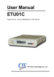
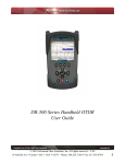
USER MANUAL
FOT-PM
Optical Power Meter
CTC Union Technologies Co., Ltd.
Far Eastern Vienna Technology Center (Neihu Technology Park)
8F, No. 60 Zhouzi St.
Neihu, Taipei 114
Taiwan
Tel: +886-2-26591021
Fax: +886-2-27991355
Email:
[email protected]
URL:
http://www.ctcu.com
FOT-PM User Manual
Optical Power Meter
Copyright © 2004, CTC Union Technologies, Inc.
All rights reserved.
All specifications are subject to change without prior notice.
Safety Instructions
Safety Terms Used in This Manual
"WARNING" identifies any procedure or practice that
could result in serious injury.
"CAUTION" identifies any procedure or practice that could
result in damage to the instrument or serious injury.
"NOTE" identifies information that may be beneficial
during the use and maintenance of the instrument.
Optical Power Meter is a laser instrument. Users should avoid looking directly into
the optic output. The use of microscopes or magnifiers should also be avoided, for
they may focus a highly intense beam onto the retina of the eye and result in
permanent eye damage.
Battery: The battery for this instrument is a rechargeable Ni-MH battery. If the
battery is unused for a long time, it should be recharged before using. If the
instrument is left idle for more than two months, the battery also should be
recharged to maintain adequate power.
Battery Power: Do not charge batteries for more than 8 hours. Battery replacement
should be done by qualified service personnel only. Do not expose batteries to fire
or intense heat. Do not open or mutilate batteries. Avoid touching the electrolyte in
the batteries, which is corrosive and may cause injury to eyes, skin or damage to
clothes.
External Power: All hand-held instruments from our company support external
power. The power requirement is: DC 13.8V/1.0A.
i
Laser Radiation: To avoid serious eye injury, never look directly into the fiber
optic output of any optic network equipment, test equipment, patch cords, or test
jumpers.
• Always avoid looking directly into the optic output port, when the
instrument is working.
• Always put the dust cap on the optical interface when the instrument is
not being used.
• Always avoid looking directly to an open end of fiber patch cords in
operation and make any open end point to a non-reflective object, if
possible.
Protective Case: When the instrument is not in use, always keep the instrument in
the case for protection.
ii
Table of Contents
Safety Instructions........................................................................................................ i
Safety Terms Used in This Manual................................................................. i
1. General Information................................................................................................ 1
1.1 Scope of this Manual ...................................................................................... 1
1.2 Unpacking and Inspection.............................................................................. 1
1.3 Introduction..................................................................................................... 2
2. Specifications .......................................................................................................... 3
2.1 Specifications for Model FOT-PM ................................................................ 3
3. Basic Operation....................................................................................................... 4
3.1 Foreword.......................................................................................................... 4
3.2 Instrument Interfaces Instructions ................................................................. 4
3.3 Maintenance of Batteries................................................................................ 5
3.4 Cleaning of Interfaces..................................................................................... 5
4. Specific Functions and Operations ........................................................................ 6
4.1 Keypad Functions ........................................................................................... 6
4.2 Specific Function Introduction....................................................................... 7
4.2.1 GUI ......................................................................................................... 7
5. Data Collection Software .....................................................................................26
5.1 Introduction...................................................................................................26
5.2 Software installation.....................................................................................26
5.2.1 Computer system requirements:..........................................................26
5.2.2 Install and Activate the data collection system ..................................26
5.2.3 GUI .......................................................................................................26
5.3.2 Menu and Tool bar...............................................................................27
5.3.3 Upload Records....................................................................................28
5.3.4 Save Records ........................................................................................29
5.3.5 Browse Stored Data .............................................................................30
5.3.6 Printing of Stored Data ........................................................................31
5.3.7 Auto Trace Drawing ............................................................................31
5.3.8 Exit the Software..................................................................................32
6. Maintenance and Calibration ...............................................................................33
6.1 Maintenance of Batteries..............................................................................33
6.2 Cleaning of Connectors ................................................................................33
6.3 Calibration Requirements.............................................................................33
7. Warranty Information...........................................................................................34
7.1 Terms of Warranty........................................................................................34
7.2 Exclusions .....................................................................................................34
7.3 Returning Equipment....................................................................................34
7.4 Contacting Customer Service.......................................................................34
iii
iv
FOT-PM
1. General Information
1.1 Scope of this Manual
Thank you for purchasing the FOT-PM optical power meter instrument.
Please read this manual carefully before using the FOT-PM fiber-optic test
instrument. Always pay attention to the warnings and cautions that appear
throughout this manual.
This manual contains the information necessary for proper operation and
maintenance of FOT-PM optical power meter, troubleshooting instructions as well
as information regarding customer services.
The FOT-PM optical power meter is carefully assembled and has undergone
rigorous mechanical, electrical, and optical inspection prior to shipment. In
addition to the instrument, the package should also include a data transfer cable,
power adapter, software installation disk and user manual. For detailed information,
please refer to the packing list.
Keep all the original package accessories in case the product needs to be
returned.
1.2 Unpacking and Inspection
This instrument has been carefully packed and shipped. Examine the
instrument for any damage that may be caused during shipment. Upon receiving
the instrument, please check for any physical damage that may be caused during
shipment. Please report any damage to the shipping agent or the representative of
the agent that sold you the instrument immediately.
To return the instrument in case of repair, calibration or
maintenance, please note that:
•
•
•
•
Be sure to pack the instrument with protection, like soft cushion, to avoid
possible damage during shipment.
Please pack with the original carton if possible. If with different size
cartoon or material, please make sure that there is at least 1.2 inch of
cushion around the instrument.
Be sure to seal the packing box firmly with tape.
Be sure to ship to your local representative or distributor in a reliable way.
1
FOT-PM
1.3 Introduction
The FOT-PM optical power meter is a new generation optical inspection tool.
This hand-held, intelligent, and easy-to-use instrument is designed for fiber
network installation, verification, routine inspection and maintenance. The
instrument features: compact, lightweight, portable, powerful, battery power
supply, great performance, and low cost. It is designed to be user friendly with a
large and easy to read LCD display. The FOT-PM has a large memory capacity
and can transfer test data to a PC by software for analysis, graphic drawing,
reporting and printing of previously stored data. Its microprocessor and linear
magnifying technology can guarantee long time accuracy. The FOT-PM combines
the functions of Laser Source (& Visible Laser) and Power Meter. It is ideal for
both single-mode and multi-mode fiber checkouts.
Features:
• Large LCD with EL backlight
• Multi-wavelength auto self-testing
• Measurement of optical loss dB
• Absolute power measurement for dBm or mW
• Store measurement data and upload to PC
• Both Continuous Wave and modulation frequency modes
• 270/1K/2K Hz modulation frequency
• Single optical connector realizing dual-wavelength output
• Power Meter to auto-trace laser source variation
• Manual and auto modes of data collection
• Auto save measurement data
• Auto data collection that can be program controlled
• Dual power, and auto charging
• Low battery indicator
• Auto power off for saving battery life
2
FOT-PM
2. Specifications
2.1 Specifications for Model FOT-PM
Model
FOT-PM
Power Meter Module Specifications
Detector Type
InGaAs
Dynamic Range (dBm)
-73 ~ +10
Accuracy (25 C & -10dBm)
+/-0.25 dB
Resolution
0.001 dB
Data Storage
4000 Measurements
Wavelength (nm)
850, 1300, 1310, 1550
Laser Source Module Specifications
Emitter Type
LD
Wavelength (nm)
1310/1550 +/-20
Spectral Width (nm)
<5
Output Power
> -7 dBm
Stability
Short-term:+/-0.05 dB,
long-term:+/-0.15dB
Modulation Frequency
270/1K/2KHz
Connector Type
FC/PC
Other Specifications
Operating Temp.
-10 C ~ 50 C
Storage Temp.
-20 C ~ 60 C
Relative Humidity
10 ~ 90% (non-condensing)
Weight
1.3 lbs. (0.6kg).
Dimensions(H×W×T)
7.7×3.9×1.7 inch (196×100×44mm)
Note: Wavelength and power range not listed in the above table can be tailored
according to customer's needs.
3
FOT-PM
3. Basic Operation
3.1 Foreword
This section of the manual will introduce the basic operation of FOT-PM
optical power meter. Specific operations of each type are elaborated in "Specific
Functions and Operations", Chapter 4 of this manual. Please read this manual
carefully for optimal performance. Should you encounter any problems during
operation, you are welcome to contact our technical staff.
3.2 Instrument Interfaces Instructions
13.8/1A
Figure 3.1 Top view of FOT-PM Series Optical Power Meter
•
•
•
Fiber Optic Output
This FC /PC connector is used for the optical power test interface and
laser source interface.
Power Adapter Jack
Power Adapter Jack requirements:13.8VDC/1.0A.
RS-232 Data port
This interface is used to upload stored measurement records to a PC
running data collection software for further statistics analysis and
reporting.
Avoid looking directly to the optic output when the
instrument is powered on.
4
FOT-PM
3.3 Maintenance of Batteries
The battery for the FOT-PM optical power meter is a
rechargeable NiMH battery. All NiMH batteries have
been correctly installed and thoroughly inspected.
Please do not open the instrument to replace batteries.
•
Caution during operation:
The following situations may cause auto power-off to the instrument:
—— The instrument will be automatically powered off when there is
insufficient power during operation and low power indicator light turns
red.
—— If with insufficient power, the instrument will be immediately shut
off several seconds after turned on, to protect the batteries from excess
discharging.
In either case, the batteries should be charged immediately.
• Caution during charging:
—— Quick charge is needed first and then switch to normal charge after
the voltage reaches a predefined figure. The ambient temperature range
for quick charge should be +10~+40 C, while for normal charge: 0~+45 C.
The batteries may not fully charge, could suffer possible damage if the
charging temperature is outside the recommended range, or the battery life
could be shortened.
—— 4 hours for quick charge.
—— Do not charge for over 8 hours.
3.4 Cleaning of Interfaces
In order to keep instrument accuracy, proper cleaning
should be performed before conducting any tests. A
lint-free cloth and reagent-grade isopropyl alcohol may be
used to clean the connectors.
If the connectors are not clean, they may cause performance errors as follows:
• Measurement errors;
• Linearity errors;
• Attenuation in optical power;
• Optical power received may appear to be out of optical range for
measurement.
5
FOT-PM
4. Specific Functions and Operations
4.1 Keypad Functions
[On/Off] This key turns the
instrument on and off. When
power is on, under default
status, the FOT-PM
automatically shuts down
after idle for about five
minutes.
[Func] This key is used to
select the fiber wavelength
and power meter interface.
[Set] This key is used to
access the main menu to
configure system parameters
and language.
[Store] This key is used to
save measurement data and
auto test results.
[Backlight] This key is used
to toggle on/off the LCD
backlight.
[Quit] This key is used to
exit the current menu and
return to the system GUI or
next upper menu.
[Enter] This key confirms
the current selection.
[
] These cursor
keys have three functions: in
GUI, they are used to adjust
LCD contrast; in the system
menu, they are used to scroll
the menu options; in laser
source and Power Meter
modes, they are used to
switch optical wavelength.
Figure 4.0 FOT-PM front view
6
FOT-PM
4.2 Specific Function Introduction
4.2.1 GUI
4.2.1.1 Contrast Adjustment of LCD
After powering on, the GUI will be displayed as follows:
FOT-PM
Figure 4.1 Boot-strap GUI of Optical Power Meter
The LCD contrast can be greatly affected by the surrounding ambient
temperature. Under normal temperature conditions, the LCD contrast is optimal.
When the ambient temperature is too high or too low, the LCD may appear too
dark or too light affecting normal display. The contrast can be modified to optimal
display by pressing the
key through the following procedures:
• Power on the instrument, the GUI is displayed (as in Figure 4.1);
• Press
key and the contrast will be intensified; Press
key and the
contrast will be weakened. Repeat the above procedures until optimal
contrast is obtained.
4.2.1.2 Power Meter and Laser Source Interface
Press [Func], the instrument will enter "Power Meter" mode, as shown in
Figure 4.2a.
Figure 4.2a Power Meter Interface
7
FOT-PM
Press [Func] again to select the "Laser Source" mode. The laser source is
displayed as shown in Figure 4.2b.
Figure 4.2b Laser Source Interface
4.2.1.3 GUI Display
As shown in Figures 4.2a and 4.2b, GUI Display description is as follows:
• Wavelength: Wavelength of laser source or power meter.
• Power Value Display: Under "Laser Source" mode, the actual power
value will be displayed; under "Power Meter" mode, actual power value
will be displayed.
• Modulation Frequency: Under "Laser Source" mode, modulation
frequency will be displayed; under "Power Meter" mode, actual frequency
value will be displayed.
• Scale: Under "Power Interface" mode, the scale is used to notify the
power change around a reference value."
" stands for the reference
point, the middle of the scale.
• AC: The instrument is powered through an AC to DC adapter; DC: the
instrument is powered by battery. When the instrument is powered by
AC/DC adapter, the internal batteries are automatically charged.
Charging internal batteries
Battery is fully charged
When the instrument is powered by battery, battery status is shown on the LCD
almost no power
over half power
low battery
full power
half power
8
FOT-PM
•
Auto Off: Sign for Auto off. After powered on, the default status of the
instrument is Auto-Off set on. If the instrument is idle for 5 minutes, it
will automatically shut off to conserve battery power. If Auto-Off
function is set off, operating time will be displayed on the LCD. To set
Auto-off function, please refer to menu operation introduction.
4.2.1.4 Wavelength Switching
Under the "Power Meter" or "Laser Source" modes, wavelength
switching can be accomplished by pressing [
].
4.2.2 Menu Configuration and Measurement Operation
Under the GUI mode, press [Set] key to enter the "Main Menu", as
shown is Figure 4.3:
Figure4.3 Main Menu
Press [
] key to make selections in the "Main Menu" and then
press the [Enter] key to enter a sub menu. Press [Quit] key to return to the
upper menu.
The "Main Menu" includes the following nine submenus:
Main Menu
Power Meter
Laser Source
Auto Test
Recall
Clear
Auto Off
Set Default
9
FOT-PM
Auto test is only applicable for long distance single-mode
fiber optical.
4.2.2.1 Power Meter
] to select
In GUI, press [Set] to enter the main menu. Use [
"Power Meter", and press [Enter]. The display will look like Figure 4.4a:
Figure 4.4a Power Meter Configuration Menu
The Configuration Menu includes the following eight submenus:
Set Menu
W/dBm
Reference
Precision
Average
Buzzer
Auto Trace
Zero
Scale
After configuration is set, please press [Quit] to exit back to the Main
Menu.
4.2.2.1.1 W/dBm
] to select W/dBm and
Under the "Power Meter" mode, press [
press [Enter]. The configuration menu is as shown in Figure 4.4b. Use
[
] to select and press [Enter] to confirm. The current unit is
marked with "*".
10
FOT-PM
Following configuration, press [Quit] to exit back to the upper menu.
Figure 4.4b Unit Configuration
"dBm" is set as default . "W" consists of: "mW", "uW",
"nW", and "pW". When "W" is selected, the FOT-PM will
choose relevant units to display automatically.
4.2.2.1.2 Reference
Under "Power Meter" mode, press [
] to select "Reference", and press
[Enter]. The configuration menu is shown in Figure 4.4c.
Figure 4.4c Reference Configuration
Under this configuration menu, there are three sub menus: "DRef", "Ref
Value", and "Ref".
DRef
Set current tested power value with relative reference value;
Ref Value
Set mid reference value for relative measurement;
Ref Reference on/off.
11
FOT-PM
•
DRef Configuration
Under the "Reference" menu, press [
] to select "DRef", and
press [Enter] to set the current power value as reference value. After
configuration, press [Quit] to go back to the higher-level menu.
• Ref Value Configuration.
] to select "Ref Value" and
Under the "Reference" menu, press [
press [Enter] to enter the configuration. The reference value can be adjusted
digit-by-digit by pressing [
]. Power value adjustment is, by default,
set to begin with the first digit. After the first digit reaches the desired value,
press [Set] to confirm. The adjustment will be automatically directed to the
next right hand digit. Adjustment is made in succession and when the
desired value is finally reached, press [Enter] to confirm and set the
adjusted value as the current reference value (as shown in Figure 4.4d).
After configuration, press [Quit] to go back to the upper menu.
Figure 4.4d Set Reference Value
•
Ref On/Off
Under the "Reference" menu, press [
] to select "Ref On/Off",
and press [Enter] to activate or deactivate relative measurement. When the
"*" appears, the function is activated; when it disappears, the function is
disabled, as shown in Figure 4.4e. Press [Quit] to back to the upper menu.
Figure 4.4e Ref On/Off Configuration
12
FOT-PM
•
Relative Measurement
] to select "Ref On/Off", and press
As in Figure 4.4e, press [
[Enter] to activate the reference measurement. Relative measurement menu
can be reached when the display unit is dB as shown in Figure 4.4f. Press
[Quit] to exit level by level.
Figure 4.4f Relative Measurement Menu
To leave the relative measurement menu, press [Set] to enter the main
menu and disable "Reference" in the power meter mode. Press [Quit] to exit
level by level. Absolute Measurement can be realized when the display units
are in dBm, as shown in Figure 4.2a.
4.2.2.1.3 Precision
There are three options for the precision of power meter measurements:
"0.1dB", "0.01dB" and"0.001dB", as shown in Figure 4.4g:
Figure 4.4g Precision Configuration
Under power meter mode, press [
] to select "Precision", and
press [Enter] to get in the config menu. Press [
] to select the
desired precision, and then press [Enter] to confirm. The selected current
number is marked with "*". Press [Quit] to exit back to the upper menu.
13
FOT-PM
4.2.2.1.4 Average
Average is a function especially designed for accuracy of measurement.
In this menu, there are four options: "average off", "10 samples", "50
samples", and 100 samples", as shown in Figure 4.4h.
Figure 4.4h Average Configuration
Under "Power Meter" mode, press [
] to select "Average", and
] to
press [Enter] to get to the configuration menu. Then press [
select sample average. Please press [Enter] for confirmation. The selected
option is marked with "*". Press [Quit] to escape back to upper menu.
"Average Off" is the default setting.
4.2.2.1.5 Buzzer
Buzzer is designed to test the stability of fiber optical power. When the
instrument detects power outside of the normal expected range, the buzzer
will automatically sound an alarm. Under "Power Meter" mode, press
[
] to select "Buzzer" and press [Enter] to enter the configuration
menu. There are three menu options: "Max", "Min", and "Buzzer", as shown
in Figure 4.4i.
Figure 4.4i Buzzer Configuration
14
FOT-PM
•
Max
Under the Buzzer configuration menu, press [
] to select "Max",
and press [Enter] to enter the Max configuration menu as shown in Figure
] to change the Max value digit by digit, (beginning
4.4j. Press [
from the left most digit. After the first digit is confirmed, press [Set] to
move to the next right digit. Adjustment is made in succession. Press
[Enter] to confirm and exit to the upper menu.
Figure 4.4j Buzzer Max Configuration
•
Min
The operation process is similar to Max Configuration. Please refer to
the above procedures.
• Buzzer On/Off
Under the "Buzzer" menu, press [
] to select "Buzzer On/Off"
and press [Enter] to activate or deactivate buzzer. When "*" appears, it
means buzzer is enabled, otherwise it is disabled. After configuration, press
[Quit] to exit back to higher level menu.
"Buzzer Off" is the default setting.
4.2.2.1.6 Auto Trace
This function can auto trace and record power variation in optical fiber
within a defined period, and draw a power variation curve after the defined
period, so as to save the manual labor in recording.
• Activate Auto Trace
For the proper implementation of the auto trace function, the mid
preference point needs to be set first. (For specific configuration, please
refer to 4.2.2.1.2), which will be "y" axis for the power variation curve.
15
FOT-PM
When auto trace function is on, "Ref key" in 4.2.2.1.2
should be off.
After setting the proper reference, select "Auto Trace" under "Power Meter" mode,
as shown in Figure 4.4k.
Figure 4.4k Auto Trace Configuration
Different trace times can be chosen by pressing [
], and then
press [Enter] to confirm. The trace time with "*" is the current setting. After
confirmation, the instrument will start auto tracing, as shown in Figure 4.4l.
Figure 4.4l Auto Trace in Progress
•
Terminate Auto Trace
Users can terminate auto trace at any time during the trace process by
pressing [Quit], and exit back to the Auto Trace menu shown in Figure
4.4k.
• Auto Trace Finish and Draw power variation curve
When the instrument completes auto tracing within the defined time, it
will show "Finished!" as shown in Figure 4.4m.
16
FOT-PM
Figure 4.4m Auto Trace Finished
After completion of auto trace, users may press [Quit] to go back to
Auto Trace configuration menu (as shown in Figure 4.4k), or they may press
[Enter] to draw power variation curve, as shown in Figure 4.4n.
Figure 4.4n Auto Trace Curve
To change the dynamic range for the instrument's auto trace curve,
adjust the mid reference value. Values outside of the range will be displayed.
If users wish to get a more detailed trace curve, please upload the data to a
PC for further processing.
4.2.2.1.7 Zero
The "Zero" function provides users with an easy way for auto calibration
of the power meter, which can be used to rectify the instrument's power
value under non-luminous state in daily testing. The procedure requires
placing the dust cap on the optical input to ensure that the tie-in is
completely enclosed and receiving no laser signal. After power on, enter the
Power Meter mode and press [
] to select "Zero". Press [Enter] to
start auto calibration. The result is shown in Figure 4.4o.
17
FOT-PM
Figure 4.4o Zero Operation
After auto calibration, the display will look like Figure 4.4p.
Figure 4.4p Auto Zero Success
If the optical sensor is not completely closed to light, it may cause
calibration failure, as shown in Figure 4.4q.
Figure 4.4q Calibration Failure
If the optical sensor is not completely closed to light, it may
cause calibration failure.
18
FOT-PM
4.2.2.1.8 Scale
Under "Power Meter" mode, press [
] to select "Scale" and
press [Enter] to enter the scale configuration menu, as shown in Figure 4.4r.
There are four scale options: +/-0.5dB, +/-1dB, +/-1.5dB, and +/-2dB. Press
] to select a scale and press [Enter] to confirm. The item showing
[
"*" is the current choice. Once the scale is changed, the scale displayed on
the screen will be changed immediately.
After configuration, press [Quit] to go back to the upper menu.
Figure 4.4r Scale Configuration
4.2.2.2 Laser Source
Under the initial GUI, press [Set] to enter the configuration menu. Use
[
] to select "Laser Source", and press [Enter], as shown in Figure
4.5a.
Figure 4.5a Laser Source Configuration
4.2.2.2.1 Laser On/Off
] to select Laser On/Off.
Under the "Laser Source" mode, press [
Press [Enter] to enable or disable laser function. When "*" appears, the laser
is enabled.
After configuration, press [Quit] to back to upper menu.
19
FOT-PM
4.2.2.2.2 CW/MOD
Under "Laser Source" mode, press [
] to select CW/MOD. Press
[Enter] to enter the CW/MOD menu, as shown in Figure4.5b. Press
] to select the desired mode, and then press [Enter] to confirm.
[
The item with "*" is the current setting.
After configuration, press [Quit] to exit to the upper menu.
Figure 4.5b Laser CW/MD Configuration
The default setting is CW (continuous wave).
4.2.2.2.3 W/dBm
Under the "Laser Source" mode, press [
] to select W/dBm, and
then press [Enter] to enter W/dBm menu, as shown in Figure 4.5c. Press
[
] to select the desired display unit and press [Enter] to confirm.
The item marked with "*" is the currently selected unit.
After configuration, press [Quit] to exit to the upper menu.
Figure 4.5c Laser W/dBm
The default setting is dBm.
20
FOT-PM
4.2.2.3 Auto Test
Using this function, the instrument can perform optical fiber loss testing
automatically and make a rough estimation of the optical fiber length. Loss
per kilometer of optical fiber cable can be set manually or by system default.
•
Enter Auto Test Menu
] to select Auto Test and press
Under the main menu, press [
[Enter] to enter the auto test configuration menu, as shown in Figure 4.7a.
Figure 4.7a Auto Test Menu
•
Manually set loss/km
During field testing, the operator can precisely configure the loss/km of
1310nm and 1550nm wavelength, to increase the accuracy of length
estimation.
Under the Auto Test menu, press [
] to select 1310nm or
1550nm. Press [Enter] to enter the menu, as shown in Figure 4.7b. Press
[
] to select any number between 0 dB/Km and 1.00 dB/Km. You
can press the arrow key and hold it to move quickly to the desired value.
Then, repeat the above procedure on a different wavelength. Press [Enter]
to confirm and exit.
Figure 4.7b Manual configuration of Loss
21
FOT-PM
•
Default
When the operator is not sure what the specific loss per km for 1310nm
and 1550nm wavelength is, they can choose the system default to make a
rough estimation of optical fiber length. The default loss per km is:
0.40dB/Km for 1310nm and 0.25dB/Km for 1550nm.
Under the Auto Test menu, please press [
] to go to the default
setting and press [Enter] to select. The loss/km will be set to default.
• Activate Auto Test
Under the Auto Test menu, press [
] to select Start Test and
press [Enter]. The optical power meter will start auto testing. The testing
process will look like Figure 4.7c. Press [Quit] to terminate the test
operation.
Figure 4.7c Auto Test in Process
•
Auto Test Report
After auto test is completed, the instrument screen will display the auto
test result report, as shown in Figure 4.7d. Users can browse the test results
of 1310nm and 1550nm wavelength tests by pressing [
].
Figure 4.7d Report of Auto Test Result
Please press [Quit] to exit to auto test configuration menu.
22
FOT-PM
Auto test is only applicable to long-distance, single-mode
optical fiber.
4.2.2.4 Recall
Using the "Recall" function, users can review stored measurement
results of 850nm, 1300nm, 1310nm, 1550nm and auto test.
Under the Main Menu, press [
] to select Recall, and then press
[Enter] to enter the Recall Menu, as shown in Figure 4.8a.
Figure 4.8a Recall Menu
Under the Recall menu, press [
] to select the corresponding
wavelength (or "auto test"), and press [Enter] to enter submenu. The screen
will display stored records of the selected wavelength (or "auto test"). Users
can browse all stored records of the selected wavelength by pressing
[
], as shown in Figure 4.8b. If there are no stored records, the
display will briefly show the message "NO RECORD!".
Please press [Quit] to exit to the upper menu.
Figure 4.8b Recall Records
23
FOT-PM
4.2.2.5 Clear
With this function, users can delete measurement records of 850nm,
1300nm, 1310nm, 1550nm, and auto test, which are stored in the
instrument.
] to select Clear, and press [Enter] to
Under Set menu, press [
enter the Clear Menu, as in Figure 4.9a.
Figure 4.9a Clear Menu
Under the Clear Menu, press [
] to select the corresponding
wavelength, and press [Enter] to enter the Delete Record menu, as shown in
Figure 4.9b. Select Yes and [Enter] for confirmation, and all stored records
of the selected wavelength will be deleted. Or select NO and press [Enter] to
exit.
Figure 4.9b Delete record confirmation
24
FOT-PM
4.2.2.6 Auto Off
The instrument has automatic shutoff function. If this function is
activated, and no keys have been pressed for 5 minutes, the instrument will
automatically shut off to save battery power.
] key to select Auto Off, and press
Under the Main Menu, use [
[Enter] key to activate or deactivate Auto-off function. When the asterisk
"*" appears, the Auto Off Function is active; when there is no asterisk, the
Auto Off function is disabled.
After setting, press [Quit] key to exit the Main Menu.
The default set is auto off on.
4.2.2.7 Set Default
With this function, users can set all parameters and configuration of this
instrument to factory defaults.
Under the Main menu, press [
] to select Set Default, and press
[Enter] to enter the Set Default interface, as shown in Figure 4.10. Then
select Yes or No, and press [Enter] to confirm. The instrument will perform
relevant operation and return back to the upper menu automatically.
Figure 4.10 Set Default Confirmation
25
FOT-PM
5. Data Collection Software
5.1 Introduction
The FOT-PM Upload Application is an upload software developed by our
company especially for the FOT-PM Fiber Power Meter. It allows stored
measurement records in the instrument to be displayed, saved or printed on a PC
through the RS232 serial port.
The data format is "comma separated values" compatible with Microsoft®
Excel. All stored records can be browsed, edited and printed in Excel.
5.2 Software installation
5.2.1 Computer system requirements:
• CPU: Pentium (or above)
• Operating System: Microsoft® Windows 98 or above
• Memory: 64MB or above
• Hard disk: 10MB or above (excluding the space of operating system)
• CD-ROM : 8x speed or above
• RS-232 serial port
5.2.2 Install and Activate the data collection system
• Start Windows98/2000, and please quit all the other application programs.
• Insert the installation disc into CD-ROM driver.
• Browse and double click "setup.exe" to install
• The installation is similar to other Windows application software. Follow
the instructions of installation wizard step by step until the installation is
completed.
5.2.3 GUI
After installation of FOT-PM Upload Application system, follow normal
procedures to run the application. The GUI will be displayed as follows:
26
FOT-PM
Figure 5.1 FOT-PM Data Collection Software GUI
5.3.2 Menu and Tool bar
Under the application, click File on the menu bar. The menu displays as
shown in Figure 5.2:
Figure 5.2 File Menu
Upload:
Open:
Close:
Save:
Print:
Exit:
Choose the right COM port, and then click the File pull-down
Menu "Upload" to upload measurement records.
Open a saved data file to browse measure results.
Close the file.
Save the testing data displayed on GUI
Print the data displayed on GUI
Exit FOT-PM Upload Application system.
27
FOT-PM
Under the application software, click Recall on the menu bar to reveal the
pull-down as shown in Figure 5.3.
Figure 5.3 Record Menu for Software
Store Record:
Select stored records accordingly.
Auto Test Record: Select Auto Test Records.
Auto Trace Record: Select Auto Trace Records.
Under the application, click Draw on the menu bar to reveal the Scale
pull-down Menu (Figure 5.4) as follows:
Figure 5.4 Draw Menu of Software
Scale=±1.0dB:Select the data scale within ±1.0dB when the curve is drawn.
Scale=±2.0dB:Select the data scale within ±2.0d when the curve is drawn.
Scale=±3.0dB:Select the data scale within ±3.0dB when the curve is drawn.
Scale=±4.0dB:Select the data scale within ±4.0dB when the curve is drawn.
AutoTrace Drawing: Click this menu to draw auto trace curve.
5.3.3 Upload Records
Power off the FOT-PM and connect it to a PC COM port via the serial
data cable. Power on the instrument and make sure the instrument is still
under the main GUI. Click Upload from the File pull-down menu bar to start
the automatic uploading of records. The GUI is shown in Figure 5.5:
Uploading records must be processed under the main
GUI. Otherwise, errors may occur.
28
FOT-PM
Figure 5.5 Upload Records
5.3.4 Save Records
After completion of uploading and filling out all necessary information,
click Save from the File pull-down to save records, as shown in Figure 5.6:
Date:
Automatically set according to PC's internal setting.
Time:
Automatically set according to PC's internal setting.
Cable:
Fill in the number of the cable under test
From:
Fill in the starting point of the cable under test
To:
Fill in the destination of the cable under test
Company: Fill in the name of the company.
Operator: Fill in the name of the operator
Location: Fill in the location of fiber
Figure 5.6 Save Records GUI
29
FOT-PM
5.3.5 Browse Stored Data
Stored data can be reopened, browsed and reviewed. Click on Open
Menu of the File pull-down menu, select a file and the GUI will display as
in Figure 5.7.
Figure5.7 Open saved file
Press Enter, records will be displayed as shown in the following figure.
Users can browse the records via mouse clicks. To close opened file, click
Close Menu from the File menu pull-down.
Figure 5.8 Browse Saved Records
30
FOT-PM
5.3.6 Printing of Stored Data
After uploading records or opening a stored record file, the user can
print records via a printer. The GUI is shown in Figure 5.9.
Figure 5.9 Printing of Stored Data
5.3.7 Auto Trace Drawing
After uploading auto trace records or opening stored auto trace record
files, users can click Auto Trace Drawing from the Draw pull-down menu.
The software will draw auto trace curves in a new window, as shown in
Figure 5.10.
Figure 5.10 Power Auto Trace Interface
31
FOT-PM
In the Figure:
Max: The maximum value of the records
Min: The minimum value of the records
Avg: The average value of the records.
Ref: The reference value.
Click on the Scale radio buttons to change the dynamic range of Y-axis.
Single-click Redraw to draw a new curve of another power range. Single
click Print to print this curve or single click Close to close this curve
drawing window.
5.3.8 Exit the Software
Click the Exit menu from the File pull-down menu to exit the
application (or click the "X" in the upper-right hand corner of the window).
32
FOT-PM
6. Maintenance and Calibration
6.1 Maintenance of Batteries
Notes for maintenance of batteries in the instrument:
1. One rechargeable NiMH battery is inside the FOT-PM. Do not replace the
battery by yourself. Please seek professional assistance.
2. If the instrument is left unused for a long time (idle for over 1 months), it
is recommended to recharge the battery every other month.
3. Do not overcharge the battery (more than 8 hours). Otherwise permanent
damage may result to the battery.
6.2 Cleaning of Connectors
Connectors must be kept clean. Special alcohol may be used to clean optic
output. Always put dust caps back on when the unit is not being used, and keep the
dust caps clean.
6.3 Calibration Requirements
Calibration of the instrument every two years is recommended. Please contact
your supplier or our agent for proper calibration.
33
FOT-PM
7. Warranty Information
7.1 Terms of Warranty
All products are guaranteed against defective components and workmanship for a
period of one (1) year from the date of shipment to customers. Any product found
to be defective within the warranty period shall be repaired or replaced free charge.
(Units must be properly packaged and shipped pre-paid back to our factory.)
This warranty does not cover accessories or optional parts.
7.2 Exclusions
The warranty on your equipment shall not be applied to defects resulting from
the following:
1. Unauthorized repair or modification
2. Improper use, negligence, or accident
We reserves the right to make changes to the product packages at any time
without having to replace or change previously purchased units.
7.3 Returning Equipment
To return equipment for yearly calibration or for any other reason, please contact
our local representative for additional information and obtain an RMA# (Return
Materials Authorization number). Please describe briefly the reasons for product
return in order to facilitate efficient service.
7.4 Contacting Customer Service
Please check our representatives for updates to this manual and additional
application information. If you need technical or sales support, please contact your
local representative.
34
Network Testers
CTC Union Technologies Co., Ltd.
Far Eastern Vienna Technologies Center
(Neihu Technology Park)
8F, No. 60, Zhouzi St., Neihu, Taipei, Taiwan
Phone:(886) 2.2659.1021 Fax:(886) 2.2.799.1355
E-mail: [email protected]
http://www.ctcu.com