1
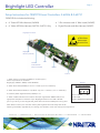
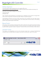
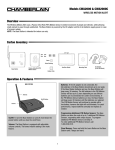
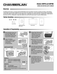
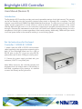
Brightlight LED Controller
Page 1
Users Manual (Revision D)
Introduction
The BrightLight LED Controller provides precise and repeatable settings of the light intensity. The intensity
can be set manually using the controller mounted rotary switch or remotely from a computer. The light
intensity is controlled using PWM (Pulse Width Modulation) technique. The light source is turned on and off
rapidly and the proportion of on and off time is varied to achieve an apparent variation in the overall
intensity. While the light source is on, the controller is supplying an accurately controlled amount of current
through it. Because the instantaneous current level is the same at all different intensity settings, the color
temperature of the light is constant regardless of the intensity setting. Additionally, PWM technique results
in minimal power losses in the controller resulting in a cool running system.
Set Up Instructions for Enclosed
Controller: 1-40042 & 1-40045
1. Attach either the USB or RS-232 communication
cable (supplied) to the appropriate receptacle on the
back of your Brightlight board and to a USB or
RS-232 port on your PC. If you are using RS-232,
please take note of which COM port is being used.
2. Connect the power supply provided with your
enclosure (12vDC 2.1mm power jack).
Note: When turned on, the controller intensity and
brightness level will always reset to 0% following a
brief flash, regardless of prior settings. It is advised
to never look directly at the light source.
navitar.com | [email protected] | 200 Commerce Dr. Rochester, NY 14623 | P: 585.359.4000 | F: 585.359.4999
Brightlight LED Controller
Page 2
Setup Instructions for OEM PCB Level Controllers: 2-62426 & 2-62731
OEM PCB Kit includes the following:
•
6” Green LED Wire Harness (2-62424)
•
3 Pin connector with 6” Wire Leads (2-62425)
•
6” Yellow LED Wire Harness (2-62733): 2-62731 Only
•
Digital Encoder and Wire Harness (2-62427)
Brightlight Connector
ATTENTION:
Electrostatic
Sensitive Dev
Brightlight:
Mini-Din (2-62732)
Hi/Low
Power Selector
(Only on 2-62732)
USB
RS-232
Power In
1. Attach the 3 pin connector (2-62425) to J2. (See Figure 1)
Power requirements are as follows:
Brightlight (1-40042/1-40045): 12vDC @ 500mA
Figure 1
J2 Power Connector
2. Attach Green LED (2-62424) to J3. Pin 1= Anode (+)/ Pin 2= Cathode (-)
3. Attach Yellow LED (2-62733) to J7 (2-62731 only). Pin 1= Anode (+) / Pin 2 = Cathode (-)
4. If desired, attach Digital Encoder (2-62427) to J6
5. Attach a USB or RS-232 communication cable (not supplied with OEM boards) to the
appropriate receptacle on the back of your Brightlight board and to a USB or RS-232
port on your PC. If you are using RS-232, please take note of which COM port is being used.
Pin 1 = +Power
Pin 2 = Gnd
Pin 3 = +Power from input jack
Note: When turned on, the controller intensity and brightness level will always reset to 0%
following a brief flash, regardless of prior settings. It is advised to never look directly at the light source.
navitar.com | [email protected] | 200 Commerce Dr. Rochester, NY 14623 | P: 585.359.4000 | F: 585.359.4999
Brightlight LED Controller
Page 3
Software Application
Choose the proper software application from the supplied USB or visit:
www.machinevision.navitar.com/software.cfm to download software and find additional developer info.
Note there are two software packages to choose from:
• Windows RS-232
• Windows USB
Upon completion of the download an icon will appear on your desktop for ease of operation. Simply double
click to launch the application and select the proper COM port to start the program.
If the BrightLight controller is turned on and the communication link is operating, the current light intensity
setting will appear in the left most display window. The intensity slider will also set itself to the matching
position along its path between 0% and 100%.
Manual Control
The intensity control is sensitive to the speed of the rotation of the knob. Turning the knob slowly will change
the intensity by 0.1%. Fast rotations will result in only minor changes in the intensity, protecting the user from
a possible sudden significant increase in brightness. The knob can be turned continuously in either direction.
Computer Control
The intensity of the BrightLight can be set and monitored remotely from a computer. The BrightLight
controller must be connected with the computer using a serial communication cable or a USB cable.
navitar.com | [email protected] | 200 Commerce Dr. Rochester, NY 14623 | P: 585.359.4000 | F: 585.359.4999
Brightlight LED Controller
Page 4
Adjusting Light Output
The light output can be adjusted in three ways:
1. Clicking on the UP and DOWN arrows next to the intensity readout window. By holding the UP or DOWN button depressed, the light
intensity change will accelerate until it reaches the maximum rate (0-100% / 2 sec).
2. Dragging the slider to the approximate desired position.
3. Entering a desired value directly into the intensity setting window and pressing the Enter key. Note that this operation will result in
an instantaneous light intensity change, not possible with manual knob control or computer control as described in 1 and 2 above.
Monitoring Light Intensity Setting
Any manual changes to the light intensity, using the knob control on the controller, are automatically reflected
in the readout and in the position of the slider.
Troubleshooting
If the On indicator fails to light (with the power supply connected and powered up and with the Power On/Off
switch in the On position), an internal failure is indicated. The internal processor controls the green “On”
indicator on the front of the controller.
If the intensity value shown is “---“, the communication link is not functioning. Check the following:
1. Proper software application is running?
3. Correct COM port selected?
2. RS-232 or USB cable securely attached?
4. BrightLight controller is powered up and green “On” indicator is lit?
If the BrightLight is not lit, but the software application indicates control, check the BrightLight source pin
connector is securely plugged into the controller.
Specifications Table
Specifications
BrightLight
Input power
12Vdc @ 500mA
Power connector
2.1mm plug, center positive
Output connector
2.5mm receptacle, tip positive
Output current source
350mA / 700mA
Output voltage compliance
0 to 5Vdc
PWM duty cycle
0.0% to 100%
PWM duty cycle resolution
0.1% from 1.0% to 99.0%
PWM frequency
~13kHz
USB protocol
2.0 compliant
USB connector
type B receptacle
Serial baud rate
automatically set
Serial connector
DB-9 receptacle (9 pin d-sub)
navitar.com | [email protected] | 200 Commerce Dr. Rochester, NY 14623 | P: 585.359.4000 | F: 585.359.4999