1
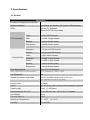
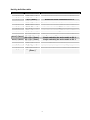
3-Port USB-PS/2 KVM Switch with DVI and Audio
Manual
1. Introduction
Thank you for purchasing our Combo DVI KVM Switch! You now have a high quality,
durable system that will enable you to control 3 Host computers and/or servers by using
PS/2 and/or USB Connectors from one console (PS/2 or USB Mouse, PS/2 or USB
Keyboard, and Monitor).
1.1 Features
1. Console your Keyboard/Mouse via either way of PS/2 and/or USB arbitrarily.
2. Controls 3 DVI computers from a single console (Keyboard/Mouse) over USB
and/or PS/2 connections.
3. Speaker enabled.
4. Microphone enabled.
5. Supports Windows, Linux, Mac OS9/OSX, Sun Microsystems.
6. Emulates a keyboard on each PC to allow your computers to boot normally,
without a keyboard error.
7. Supports hot-swap. All devices connected to the KVM can be added or removed
at any time, without shutting the unit down.
8. Supports 2 types of switching: (1) Hardware Push Button, (2) Hot-Keys on PS/2
9.
10.
11.
12.
13.
14.
15.
and/or USB of keyboard arbitrarily.
Supports Auto-Scan function to switch video automatically among computers in
preset intervals sequentially.
Supports LED display for PC status monitoring.
Supports DVI UXGA resolutions up to 1600 x 1200 @ 60HZ.
Supports Beeper during switching enabled.
Self powered through USB connection.
Fully compliant with the USB 1.1/ 2.0 specification
Comply with DVII specification and support analog display devices
1.2 LED Indicators:
Selected : RED LED indicates that the KVM Switch is selected to the corresponding
PC.
On-Line : GREEN LED indicates that the KVM Switch is ready to the corresponding
PC.
1.3 Package Contents
The product you purchased should contain the following equipment and accessories:
1. 1 x 3-Port Combo DVI KVM Switch .
2. 2 x KVM cable sets, 1,8 m
3. 1 x User Manual.
2
2. Specifications
2.1 General
Specification
Number Of Computers Controlled
3
Selection Method
Push Button and Hot-Key (PS/2 and/or USB Keyboard)
LEDs
Red for PC Selection
Green for PC On-Line ready
PC Connectors
Console Ports
Video
3 x DVI UXGA female
USB
3 x USB - B type female
Speaker
3 x audio female jacket
Microphone
3 x audio female jacket
Keyboard
1 x 6 pin mini-DIN female
Mouse
1 x 6 pin mini-DIN female
Video
1 x DVI UXGA female
Keyboard
1 x USB - A type female
Mouse
1 x USB - A type female
Speaker
1 x audio female jacket
Microphone
1 x audio female jacket
Auto-Scan Interval
From 5 to 250 Seconds
DDC, DDC2 DVI UXGA monitor
Up to resolution: 1600 x 1200
Hot Swappable
Yes
Operating systems supported
Windows 98SE/ME/2000/XP/2003 Server, Linux
Mac OS9/OSX and Sun Microsystems
Device driver
No Need
Power
By PS/2 and/or USB or External Power Adaptor (Optional)
Cable Length
6 feet (1.80 Meter)
Dimensions (L X W X H)
21.5 x 8.8 x 4.5 cm (5.5 X 3 X 1.7 inches)
Unit Weight
650 g
Housing material
Metal
Operating Temperature
32~ 122°F
Humidity
0%~80%RH
3
(0~ 50°C )
3. System Requirements
Console
DVI monitor capable of the highest resolution.
PS/2 and/or USB Keyboard/Mouse
Computer or Server
The following equipment must be equipped with each computer or server.
- Type A USB port.
- DVI connector.
Cables
The Combo DVI KVM Switch is using separate (DVI + USB/Audio) cables.
To purchase the specific cable sets, please contact your dealer.
4. Single installation
4.1 Precaution:
1. Running under OS Windows 98 , we suggest that the PC must be plugged
to PS/2 ports, because of Windows 98 is not supporting installation at first time
as through USB HID installation driver.
2. There are some older PCs supporting USB ports during booting, but you need
to open BIOS USB setting at first.
3. The KVM switch does not support the USB keyboard which has built-in
USB HUB.
4.2 The DVI KVM SWITCH Installation: (Important note)
The DVI KVM can only support the DDC2, DDC1 pass through mode for the
HOST DVI VGA card, so it is important that you can not power on all the
computers at the same time, otherwise it will be possible that you will get a
blank screen when you switch to other hosts. The right way to power on
computers is : To switch the KVM to the selected host which you want to
power on, then turn on the host, after you can see the Window desktop
environment shown on selected host, then you can switch to other Hosts, as
same method to turn on selected host and wait for the window desktop screen
show up. After all the computers have been turned on under above
procedures means all of continuous operations will be working fine as well.
4
5. Operations
The 3-Port Combo Free DVI KVM Switch has the ability to switch the keyboard,
video, mouse simultaneously
Note: When using the two-step Hot Key sequences, the keys must be pressed
within 5 seconds; otherwise the Hot Key action will be terminated.
5.1 Push Button on front panel
5.2 Hotkey Selection ( USB and/or PS/2 keyboard )
Note:
If your keyboard is without < Scroll Lock > button,
please press < Caps Lock > or <Num Lock > instead of Scroll Lock ( ref. 5.2.0 ).
5.2.0 Instead hotkey Selection
Hot Key:
[Ctrl] → [Ctrl] → [Caps Lock] → [Enter] : The hotkey changed to [Caps Lock]
[Ctrl] → [Ctrl] → [Num Lock] → [Enter] : The hotkey changed to [Num Lock]
[Ctrl] → [Ctrl] → [Scroll Lock]→ [Enter] : The hotkey reversed to [Scroll Lock]
Note : The default hotkey setting is <Scroll Lock> button as if you chang the
hotkey default setting, the new setting will effect on the KVM switch until
power off or reset.
5.2.1 PCs Selection
Hot Key:
[Scroll] → [Scroll] → [ 1 ] → [Enter]
[Scroll] → [Scroll] → [ 2 ] → [Enter]
[Scroll] → [Scroll] → [ 3 ] → [Enter]
or
or
5
You can synchronize the PC selection, by using the following two-step Hot Key
sequence. To send commands to the Combo Free DVI KVM Switch, press the
[Scroll] key twice (Step 1), then press key [1] or [2] or [3] and [Enter] (step 2) to
assign the PC to a particular PC. ( If you press key [1] or [2] or [3] on the number
pad, the keyboard, mouse & video will also be switched synchronously )
5.2.2 Auto-Scan Function
Hot Key:
[Scroll] → [Scroll] → [S] → [Enter] to BEGIN.
[Scroll] → [Scroll] → [S], → [Enter] to STOP.
You can activate the Auto-Scan function by using the following two-step Hot Key
sequence. To send commands to the Combo Free DVI KVM Switch, press the [Scroll]
key twice (Step 1), then press [S] and then press [Enter] (Step 2). When you press
the Auto-Scan hot key sequence, the Combo Free DVI KVM Switch alternates
between the three PCs and displays them on the monitor.
Each PC is display one of time interval from 5 ~ 250 seconds (The interval is
adjustable) before switching to the next. When you press the Auto-Scan Hot Key
sequence again, the Auto-Scan will stop and the monitor screen will jump back to the
original PC.
Adjustable scan time interval setting ( 5 ~ 250 sec. )
Hot-key: Pressing the <Scroll >, <Scroll > then <S> and <10 ~250 > <Enter>
6
5.2.3 Beeper Enable
Hot Key:
[Scroll] → [Scroll] → [B] → [Enter] to Disable
[Scroll] → [Scroll] → [B] → [Enter] to Enable
.
The Speaker/Beeper’s default setting is “Enable”. While the switching connections
are activated and Speaker/Beeper is in “Enable” status, the beeper has a short
beeping sound.
5.3 Audio (Speaker + Microphone) Selection
5.3.1 ( PC+Audio ) Combination Selection
Hot Key:
[Scroll] → [Scroll] → [ F1 ]→[Enter]
[Scroll] → [Scroll] → [ F2 ]→[Enter]
[Scroll] → [Scroll] → [ F3 ]→[Enter]
or
or
7
5.3.2 Single Audio ( Speaker + Microphone ) Selection
Hot Key:
[Scroll] → [Scroll] → [A] →[Enter] to enable or disable the audio auto switch mode
[Scroll] → [Scroll] → [A] → [1]→ [Enter] to select PC1 Speaker and Microphone
[Scroll] → [Scroll] → [A] → [2]→ [Enter] to select PC2 Speaker and Microphone
[Scroll] → [Scroll] → [A] → [3]→ [Enter] to select PC3 Speaker and Microphone
Note 1: Audio auto switch mode, the default setting of KVM switch is enabled,
means when you used the push button, the PCs and Audio will be switched
at the same time. In case of the Audio auto switch mode is disabled, then the
push button only switch PCs.
Note 2: One long sound – Audio auto switch disabled
Two short sound – Audio auto switch enabled
A
8
Hot Key definition table
Step 1
Step 2
[Scroll] + [Scroll]
[1] + [ Enter ]
[2] + [ Enter ]
[3] + [ Enter ]
Switch the active connection to PC 1
Switch the active connection to PC 2
Switch the active connection to PC 3
[A] + [ Enter ]
[F1] + [ Enter ]
[F2]+ [ Enter ]
[F3] + [ Enter ]
Disable or enable the Audio auto switch mode
Combined switching (PC+Audio) to PC 1
Combined switching (PC+Audio) to PC 2
Combined switching (PC+Audio) to PC 3
[Scroll] + [Scroll]
[Scroll] + [Scroll]
[Scroll] + [Scroll]
[Scroll] + [Scroll]
[Scroll] + [Scroll]
[Scroll] + [Scroll]
Action
[Scroll] + [Scroll] [A] + [1] + [ Enter ]
Single switching the active audio to PC 1
Single switching the active audio to PC 2
Single switching the active audio to PC 3
[Scroll] + [Scroll] [A] + [2] + [ Enter ]
[Scroll] + [Scroll] [A] + [3] + [ Enter ]
[Scroll] + [Scroll]
[B] + [ Enter ]
Disable or enable beeper
[Scroll] + [Scroll]
[S] + [Enter]
Activate the Auto-Scan mode, default 5 sec.
[Scroll] + [Scroll]
[S] + [5 -250 ] +
[ Enter ]
Select the Auto-Scan interval from 5 to 250 Sec.
9
Sun Microsystems Function Key Emulation:
There are 16 special functions on the Sun Microsystems keyboard, the Combo Free
DVI KVM Switch can emulate these function keys via the PS/2 and/or USB keyboard.
Here is the mapping table for these functions operation. To active these emulation on
the PS/2 and/or USB keyboard, you have to press the LEFT Window KEY first (this
key usually is located between the left [Ctrl] and left [Alt]), then choice the second
relative key.
Sun Micro System
Function Key
Stop
PS/2 Keyboard
Props
L_Win & L_Ctrl
Compose
L_Win & L_Shift
Front
L_Win & F1
Open
L_Win & F2
Find
L_Win & F3
Again
L_Win & F4
Undo
L_Win & F5
Copy
L_Win & F6
Paste
L_Win & F7
Cut
L_Win & F8
Help
L_Win & F11
Power
L_Win & F12
Mute
L_Win & 1
Volume Down
L_Win & 2
Volume UP
L_Win & 3
L_Win & L_Alt
10
FCC Statement
This device generates and uses radio frequency and may cause interference to radio and television reception if not installed
and used properly. This has been tested and found to comply with the limits of a Class B computing device in accordance with
the specifications in Part 15 of the FCC Rules. These specifications are designed to provide reasonable protection against such
interference in a residential installation. However, there is no guarantee that interference will not occur in a particular installation.
If this device does cause harmful interference to radio or television reception, which can be determined by plugging the device
in and out, the user can try to correct the interference by one or more of the following measures:
Reorient or relocate the receiving antenna.
Increase the separation between the device and receiver.
Connect the computer into an outlet on a circuit different from that to which the receiver is connected.
Consult the dealer or an experienced radio/TV technician for help.
Safety Information:
This device may only be operated in enclosed, dry rooms. To prevent the risk of fire or electrical shock, the device must be
protected from moisture. In the event of a defective power plug, please contact an authorized retailer. In the event of damage to
the housing or the power plug, do not operate. Do not open the device. Repairs may only be performed by an authorized
retailer.
Note:
In the event of incorrect installation and improper use in a residential area, the device may cause disruptions in radio devices
and other electronic devices. Proper use means that the device is operated with shielded connector cables as far as possible,
for network products also with shielded cables of category 5e and higher. The device was tested and lies within the limits for
computer accessories of class A according to the requirements of EN 55022.
Warning:
This is a class A device. This device can cause radio interference in residential areas; in this case, the operator may be
required to perform and bear the costs for appropriate measures.
Conformity Declaration:
The device fulfils the EMC requirements of EN 55022 class A for ITE and EN 55024. Devices with external or built-in power
supply also fulfil the requirements of EN 61000-3-2 and EN 61000-3-3. The basic protection requirements of the “EMC
Directive” 89/336/EEC are therefore fulfilled. The CE conformity has been certified. The corresponding declarations are
available from the manufacturer.
Trademarks:
All company, brand and product names used in these instructions are trademarks or registered marks of the corresponding
companies.
11