1
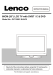
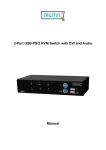
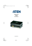
2-port USB/DVI Cable KVM Switch with Audio User’s Manual Index 1. INTRODUCTION……………………………………………………………………………………………2 1.1 FEATURES …………………….…..………………………………….………………………… ………2 1.2 PHYSICAL DIAGRAM…….…………………………………...…..………………………………………3 1.3 PACKAGE CONTENTS…………………………………...……………..………………………………...3 2. SPECIFICATIONS………………………………………………………………………………………….4 2.1 GENERAL……………………………………………………………...…………………………………4 3. INSTALLING THE DVI CABLE KVM SWITCH…………………………………………………………5 3.1 SYSTEM REQUIREMENTS………………………………………….…………………………………….5 3.2 HARDWARE INSTALLATION………...………………………...……………..……………………………5 3.3 NOTICE FOR SUN MICRO SYSTEM USER……………………………………………………….……….5 3.4 HOT SWAPPABLE……………………….……………...……………………..………………………….5 3.5 DRIVER INSTALLATION(WINDOWS 98/SE ONLY)..………………………………………………………5 4. OPERATION……………………………………………………………………….…….………………….8 4.0 PUSH BUTTON……..…………………………………………………………………………………….8 4.1 HOT-KEY OPERATION……………………………………………………………………………………8 4.2 PC SELECTION (WITHOUT AUDIO)….………………………………………………………………..…8 4.3 AUTO-SCAN FUNCTION……….……….……………….………………………………………………..9 4.4 SINGLE AUDIO (SPEAKER) SELECTION……………….…………………………………………………10 1 1. Introduction Thank you for purchasing 2-port USB/DVI Cable KVM Switch with Audio! You now have a high quality, durable system that enables you to control two computers from one console (USB Mouse, Keyboard, and Monitor). In addition, this device allows you to independently control and switch audio between two computers. 1.1 Features 1. Controls 2 computers from a single console (Keyboard/Mouse) over USB connection. 2. Support Window 98SE/ME/2000/XP/Vista/2003 server, Mac , Linux 3. Compliant with DVI 1.1 standards, 4. Supports speaker and Microphone. 5. Emulates a keyboard on each PC to allow your computers to boot normally without a keyboard error. 6. Supports hot-swap. All devices connected to the KVM can be added or removed at any time, without shutting the unit down. 7. Supports USB keyboard Hot-Key Switch and push buttons for easy operation. 8. Supports Auto-Scan function to alternate video between both computers in preset intervals. 9. Supports LED display for PC and audio status monitoring. 10. Supports max resolution : 1920x1080@60Hz 11. Supports Plug and Play. 12. Self powered through USB connection. 13. Supports independent audio switching. 2 1.2 Physical Diagram PC connection 2 LED Indicators (Green) PC connection 1 LED Indicators (Green) PC 2 LED Indicators (Red) PC 1 LED Indicators (Red) USB Keyboard DVI Output USB Mouse PC2 Selection Push Button PC1 Selection Push Button Speaker Jack MIC Jack PC LED Indicators: RED LED indicates that the 2-port USB/DVI Cable KVM Switch is switched to the corresponding PC. PC connection LED Indicators: GREEN LED indicates the status of PC connection. Package Contents 1. One 2-port USB/DVI Cable KVM Switch with Audio. 2. User Manual. 3 2. Specifications 2.1 General Specification Number Of Computers Controlled Selection Method USB Versions supported LEDs USB Video Speaker Microphone KVM Body Console Ports Keyboard / Mouse Video Speaker Microphone Auto-Scan Interval DDC, DDC2 monitor Hot Swappable PC Connectors 2 USB Keyboard Hot Key and Push button 1.1 Red for PC Selection Green for PC ON-Line Selection 2 x Type A USB Connectors 2 x DVI (male) 2 x Stereo speaker plugs 2 x Mono microphone plugs 2 x Video Connector (male) 2 x Type A USB Connectors (female) 1 x DVI (female) 1 x Stereo speaker jack 1 x Mono microphone jack 5~60 Seconds Yes (Max. Resolution: 1920x1080)@60Hz Yes Operating systems supported Windows 98SE/ME/2000/XP/Vista/2003 Server, Mac, Linux Device driver Power Cable Length Dimensions (LxWxH) Unit Weight No By PC USB power 1.20 Meter 65 x 85 x 25 mm 450 g 4 3. Installing the USB/DVI Cable KVM Switch 3.1 System Requirements 1. A PC with USB port and 1 DVI port. 2. Windows 98 or later, Mac OS 8/9/OS X, Solaris 8 (SUN BLADE 100), Linux Kernel 2.3 or later. 3. USB Keyboard and mouse. 4. Monitor with DVI port 3.2 Hardware Installation 1. Turn off computers. 2. Connect KVM switch cables to DVI, USB, Speaker and Microphone ports on computers. 3. Plug the USB keyboard, USB mouse, and monitor to the corresponding connectors on KVM Switch. 4. Plug the Speaker and Microphone to the corresponding jacks on KVM Switch. 5. Turn on computers Note: If the monitor can not support the maximum resolution it should have with KVM switch, please restart the computers to work out the problem. 3.3 Notice for Sun Micro System user Since some Sun Micro system will detect the monitor information, if system fail to get information from the Monitor, then you won’t get any screen came out. So for safety, “YOU MUST SWITCH USB KVM SWITCH TO THE SUN MICRO SYSTEM” before you power on the Sun Micro System. After you seeing the screen from the Sun Micro System, then you can switch to any other Host. If you have multiple Sun Micro systems, then you have to repeat this procedure one by one. 3.4 Hot Swappable The 2-port USB/DVI Cable KVM Switch supports hot-swap technology. All the components can be added or removed at any time without shutting the PC down. 3.5 Driver Installation (Windows 98/SE only) After you connect the 2-port USB/DVI Cable KVM Switch to your PC, Win 98 will automatically detect the device and prompt for the driver installation. Please install the 2-port USB Cable KVM Switch by the following instruction from Step AE. Please have your Windows 98 CD ready. 5 A. Press “Next” to Continue. (Ref. Fig. A) Fig. A B. Select “Search for the best driver for your device” and press “Next” to continue. (Ref. Fig. B). Fig. B C. Please insert the “Windows 98” CD into your CD-ROM drive. Click “CDRom drive” and press “Next” to continue. (Ref. Fig. C) Fig. C 6 D. Press “Next” to start the installation process. (Ref. Fig. D) Fig. D D1. Sometimes Windows cannot locate the necessary driver automatically. So you need to choose “Browse” to specify the location of the driver on your “Windows 98” CD manually. * (Ref. Fig. D1) Fig. D1 * The driver might be located in a different directory from the figure above. D2. Press “OK” to continue (Ref. Fig. D2) Fig. D2 7 E. Press “Finish” and Windows has finished installing the USB Human Interface Device driver for PS/2 keyboard & mouse. (Ref. Fig. E) Fig. E 4. Operation The 2-port USB/DVI Cable KVM Switch can switch the keyboard, video, mouse by pushing button and Hot Key. The switching of Audio inputs ( speaker & microphone) is independent and be controlled by Hot Key only. The Audio inputs is not be switched with PC selection. Note: When using the two-step Hot Key sequences, the keys must be pressed within 5 seconds, otherwise the Hot Key action will terminate. 4.0 Push Button User can switch Computers ( Keyboard , Mouse and Video inputs) by pressing push button. 4.1 Hot-Key operation Note: If your keyboard is without < Scroll Lock > button, then you can change the hotkey setting and use < Caps Lock > or <Num Lock > to instead of Scroll Lock (please reference 4.2). 8 4.2 PC Selection (Without Audio) Hot Key: Switch to PC1 [Scroll] + [Scroll] + [ 1 ] Switch to PC2 [Scroll] + [Scroll] + [ 2 ] Switch to Next PC [Scroll] + [Scroll] + [→ ] or [↓] Switch to Previous PC [Scroll] + [Scroll] + [← ] or [↑] 4.3 Auto-Scan Function Hot Key: [Scroll] → [Scroll] → [S] to BEGIN. There is about 10 seconds for the initial time waiting. Press the [Esc] key to STOP. NOTE : [Esc] will stop the atuoscan operation and make the KMV jump to the current scanning PC. You can start the Auto-Scan function by using the following two-step Hot Key sequence. To send commands to the KVM Switch, press the [Scroll] key twice (Step 1), then press [S] (Step 2). When you press the Auto-Scan hot key sequence, the KVM Switch will switch between two computers and display the video inputs on the monitor. Each video input is displayed in certain time interval from 5 ~ 60 seconds (The interval is adjustable) before switching to the next. You can press any key to stop Auto Scan function. Under Auto-Scan mode, the KVM will ignore the mouse operation and you will not see the cursor move on the screen. 9 Adjustable scan time interval setting ( 5 ~ 60 sec. ) Hot-key: Pressing the <Scroll >, <Scroll > then <S> and < n> *n = 1~ 9 Scan time Scan time <n> <n> interval 1 2 3 4 5 interval 5 10 15 20 25 6 7 8 9 30 35 40 60 4.4 Single Audio (Speaker) Selection Hot Key: [Scroll] → [Scroll] → [ F1 ] to select PC1 Audio (Speaker) [Scroll] → [Scroll] → [ F2 ] to select PC2 Audio (Speaker) Hot Key definition table Step 1 [Scroll] + [Scroll] Step 2 Action [→ ] or [↓] Switch to the next PC [Scroll] + [Scroll] [1] Switch the active connection to PC 1 [Scroll] + [Scroll] [2] Switch the active connection to PC 2 [Scroll] + [Scroll] [F1] Switch PC1 Audio to console [Scroll] + [Scroll] [F2] Switch PC2 Audio to console [Scroll] + [Scroll] [S] Activate the Auto-Scan mode, default 10 sec. [Scroll] + [Scroll] [S] + [1~9 ] Select the Auto-Scan interval from 5 to 60 Sec. 10 Disclaimer Information in this document is subject to change without notice. The manufacturer does not make any representations or warranties (implied or otherwise) regarding the accuracy and completeness of this document and shall in no event be liable for any loss of profit or any other commercial damage, including but not limited to special, incidental, consequential, or other damages. No part of this document may be reproduced or transmitted in any form by any means, electronic or mechanical, including photocopying, recording or information recording and retrieval systems without the express written permission of the manufacturer. All brand names and product names used in this document are trademarks, or registered trademarks of their respective holders. FCC Statement This device generates and uses radio frequency and may cause interference to radio and television reception if not installed and used properly. This has been tested and found to comply with the limits of a Class B computing device in accordance with the specifications in Part 15 of the FCC Rules. These specifications are designed to provide reasonable protection against such interference in a residential installation. However, there is no guarantee that interference will not occur in a particular installation. If this device does cause harmful interference to radio or television reception, which can be determined by plugging the device in and out, the user can try to correct the interference by one or more of the following measures: Reorient or relocate the receiving antenna. Increase the separation between the device and receiver. Connect the computer into an outlet on a circuit different from that to which the receiver is connected. Consult the dealer or an experienced radio/TV technician for help. 11