1
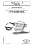
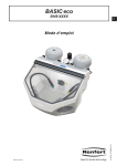
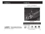
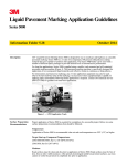
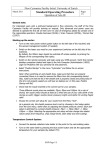
Repair Guideline Basic classic
Art. Nr. 2945.XXXX
04/2005
Valid for version D
Index
1
2
3
4
5
6
7
8
General safety instruction: .............................................................................................. 3
1.1 Used symbols........................................................................................................ 3
1.2 Qualification and training ....................................................................................... 3
1.3 Repair works safety instruction.............................................................................. 3
1.4 Modifications without manufacturer’s permission................................................... 4
1.5 Liability exclusion .................................................................................................. 4
Contact and Service address: ......................................................................................... 5
Needed tools and utilities: ............................................................................................... 5
Overview......................................................................................................................... 6
4.1 Description / Application area................................................................................ 7
4.2 Ambient conditions (in accordance with DIN EN 61010)........................................ 7
4.3 Technical data:...................................................................................................... 7
Service Works................................................................................................................. 8
5.1 Removing / attaching a Tank................................................................................. 8
5.2 Pressure gauge replacement ................................................................................ 9
5.3 Maintenance unit replacement............................................................................... 9
5.4 Tank selector replacement ...................................................................................10
5.5 Ballast unit replacement: ......................................................................................11
5.6 Mixing chamber replacement ...............................................................................12
5.7 Cleaning of mixing chamber and nozzles .............................................................13
5.8 Filter set replacement...........................................................................................13
5.9 Blasting hose replacement ...................................................................................14
5.10
Glass pane replacement ...................................................................................15
Final testing ...................................................................................................................16
Maintenance recommendation .......................................................................................16
7.1 Maintenance table ................................................................................................17
Spare parts ....................................................................................................................17
8.1 Spare part list for Version A, B C and D ...............................................................18
8.2 Spare part drawing – version D ............................................................................19
Note!
These information are indented for authorized repair companies only. Repair
works other than the described in these guidelines are not allowed. In any other
case, please contact Renfert in order to coordinate the further procedure.
Page 2 / 19
1
General safety instruction:
This repair guideline contains basic information, which should be observed during the
repair of the unit. Therefore, this guideline should be read by the service technician
before starting to carry out repair works. Furthermore not only the in the main topic
mentioned general safety information have to be observed, also the specific safety
instruction in other topics must be observed.
1.1
Used symbols
The safety instruction in this guideline must be read and observed necessarily.
Additionally different symbols are used.
Warning notices: read and follow them carefully!
Warning notices should protect you from danger and will help you to avoid damages
of the device.
Attention: danger of life caused by electric shock!
When you see this sign, you should always check for the appliance for being voltage
free and being protected against enabling by mistake.
Caution!
The Caution! box denotes a hazard. It calls attention to a procedure, practice, or the
like, which, if not correctly performed or adhered to, could result in personal injury.
Do not proceed beyond a caution box until the indicated conditions are fully
understood and met.
Safety instructions, which are located direct at the unit, must be observed necessarily.
1.2
Qualification and training
Personnel performing repair and maintenance works described in this guideline shall
meet the corresponding requirements. Otherwise, the personnel have to be trained
prior to performing repair and maintenance works to ensure that the personnel
understand the information in these guidelines completely.
1.3
Repair works safety instruction
The Basic classic is an electrical device with inherent hazard potential. This device
may only be installed and operated by authorized specialists after examination of
Page 3 / 19
compliance with locally applicable standards. The following safety instruction must be
strictly observed during operation and maintenance works.
Prior to commissioning, compare the information on the nameplate with the specifications
of the local mains power network and the connection values for compressed air.
Always disconnect the unit from the compressed air supply prior to performing any
maintenance tasks.
Never operate a sandblaster without a suitable dust extraction unit or suitable personal
protective clothing, as this can be detrimental to your health. The type of dust extractor
must relate to the type of dust produced by your sandblasting work. It is imperative to
adhere to the legal regulations (in Europe this means EN 60335-2-69).
When working on the tank (filling up, cleaning, and maintenance) wear protective glasses
for protecting your eyes.
Any residue of abrasive material on the gasket may lead to leakage and early wear of the
gasket. After filling up clean the thread and the gasket and close the lid properly.
Solvents and tensides can create micro cracking in the plastic (danger of explosion!).
Clean the tank and the lid only with a dry cloth. Do not write or stick something on the
tanks.
Check the tanks and the lids regularly on damages and replace them in case of doubt.
Check the tank cover for correct seating prior to beginning operation. Covers that are not
securely closed can suddenly be blown off as the tank pressure increases. The resulting
flying parts and abrasive represent a serious hazard.
Improper use can result in the risk of eye or skin injuries.
Never direct the nozzles towards your eyes or uncovered areas of skin!
Never work with the view screen open!
Caution!
Always wear appropriate eye protection when operating the unit! Failure
to wear eye protection can result in eye injuries due to airborne particles.
Do not employ the foot switch when only compressed air supply hose is connected. The
loose hose could wrap around itself and cause serious injury.
Always disconnect the unit from the mains power supply prior to replacing the fluorescent
tube.
Never press on or bend the lamp body during replacement (breakage risk). If necessary,
wear gloves or use a cloth.
Regularly inspect all connecting lines and hoses (e.g., power cord and compressed air
hoses) for damage (e.g., kinks, cracks, porosity). The unit may not be operated if the
power cord is damaged.
1.4
Modifications without manufacturer’s permission
Modifications of the unit, other than described in the user manual are only allowed
after getting permission from Renfert. Original spare parts are important for the
equipment safety. The use of other than original spare parts is not allowed.
1.5
Liability exclusion
Renfert GmbH shall be absolved from all claims for damages or warranty if:
Page 4 / 19
2
The product is employed for any purposes other than those cited in the operating
instructions.
The product is altered in any way other than those alterations described in the operating
instructions.
The product is repaired by other than an authorized facility or if any but Renfert OEM
parts are employed.
The product continues to be employed, despite obvious safety faults or damage.
The product is subjected to mechanical impacts or is dropped.
Contact and Service address:
If you have question regarding the use of in case of service please contact the
following address:
Renfert GmbH
Industriegebiet
78247 Hilzingen
Germany
Phone:
Fax:
++49 (07731) 8208-0
++49 (07731) 8208-70
Mail: [email protected]
Internet: www.renfert.com
Customers in the USA, Canada and Mexico please contact
Renfert USA Inc.
3718 Illinois Avenue
St. Charles, Illinois 60174
U.S.A
Phone:
Toll free:
Fax:
++1 630 762-1803
1 800 336-7422
++1 630 762 9787
Internet: www.renfertusa.com
3
Needed tools and utilities:
Set of Allen keys
Set of screwdrivers (slotted and Phillips style)
Set of box/open-end wrenches (metric)
Loctite 638 Metal glue
Loctite 242 retaining compound
Torque wrench (not essential)
Face Spanner, size 7-40 (Renfert Art. Nr. 33254)
Set of pliers
Page 5 / 19
4
Overview
D
A
C
B
F
Fig.1 - Overview
Pos.
Description
A
On/off switch for lighting
B
Tank selector
C
Abrasive tank
D
Pressure gauge
E
Pressure regulator
F
Blasting hose with handle
Page 6 / 19
E
4.1
Description / Application area
The Basic classic units are designed for use in dental laboratories to remove
investment residues, oxides on cast objects, and for surface treatment.
Caution!
The Basic classic is 230V~ or 120V~ operated. Internal parts of the unit
can carry high voltage. Before starting service works, always remove
the mains plug
4.2
Ambient conditions (in accordance with DIN EN 61010)
The unit may only be operated:
Indoors;
Up to an altitude of 2,000 m [6,500 ft] above level;
At an ambient temperature range of 5 – 40 [41 - 104ºF];
At a maximum relative humidity of 80% at [87.8ºF], dropping linearly to 50% relative
humidity at 40ºC [104ºF];
With a mains power supply whose voltage fluctuations do not exceed 10% of the rated
value;
Under contamination level 2 conditions;
Under over-voltage category II conditions.
4.3
Technical data:
Voltage:
230-240 V / 50/60 Hz
90-120 V / 50/60 Hz
Power consumption Lamp:
11 W (230 V)
9 W (120 V)
Overall power consumption:
17,3 W (230 V)
9,5 W (120 V)
Working pressure:
1 - 6 bar [14,5 - 87 psi]
Connecting pressure:
6 - 8 bar [87 - 116 psi]
Air consumption:
120 l/min. at 6 bar [87 psi]
Blasting chamber volume:
14 l
Tank capacity:
1000 ml each
Ø hose connection
inner: 4 mm [0,16 inch]
pressured air:
outer: 6 mm [0,24 inch]
Ø Size of connection point for inner: 35 mm [1,38 inch]
external extraction unit
outer: 40 mm [1,58 inch]
Dimensions (WxHxB)
360 x 265 x 385 mm
(4 Tank version)
[14,18 x 10,44 x 15,17 inch]
Weight 2 tank version (empty): approx. 6,5 kg
Cable length:
2 m [78,74 inch]
Noise level according to DIN
Lp(A) <72dB(A)
45635-01-KL3
Page 7 / 19
5
Service Works
Caution!
Generally acknowledged technical rules for safe and correct working
must be observed.
5.1
Removing / attaching a Tank
f
a
b
g
h
d
e
c
Fig. 2 - Tank and body
Switch-off the unit.
Disconnect from mains supply.
Disconnect from pressured air supply.
Loosen the knurled nuts (fig. 2 f).
Hang out the tank (fig. 2 b) at the body (fig. 2 a).
Pull the pressured air hose (fig 2 g) out of the push-in connector at the tank.
Remove the blasting hose (fig. 2 c) by opening the hose clamp (fig. 2 d) and pulling it
from the hose nozzle (fig. 2 e).
After the repair put the blasting hose back to the hose nozzle and fasten it with the hose
clamp.
Push the pressured air hose completely into the push-in connector.
Restore the tank at the body and fasten the knurled nuts (fig. 2 f).
Take care that the tank retaining collar (fig 2 h) is hung in at the body correctly.
Page 8 / 19
5.2
Pressure gauge replacement
b
a
Fig. 3 - Pressure gauge
Pull the pressured air hose out of the push-in connector (fig. 3 b) at the pressure gauge.
Remove the push-in connector and take the pressure gauge out of the body.
Insert the new pressure gauge into the body. Take care that the pressure gauge is
mounted even.
Fasten the push in connector (fig. 3 b) at the gauge.
Lock the push-in connector thread with Loctite 242 retaining compound.
Push the pressured air hose into the push-in connector completely.
5.3
Maintenance unit replacement
b
c
d
a
Fig. 4 - Maintenance unit
Disconnect from mains supply.
Disconnect the unit from pressured air supply.
Page 9 / 19
Remove out the pressured air hose (for the foot switch) from the hose nozzle (fig.4 a).
Pull out the pressured air hose from the push-in connector (fig.4 d).
Unscrew the retaining nut of the maintenance unit (fig 4 b) and remove the maintenance
unit (fig. 4 a) from the body.
Install the new maintenance unit (fig. 4 a) from the lower side of the body and attach it
with the nut (fig. 4 b).
Mark the bended hose nozzle (fig. 4 c) with a yellow adhesive tape.
Push the pressured air hose into the push-in connectors (fig. 4 d) completely and mount
the hose to the foot switch.
5.4
Tank selector replacement
e
a
b
c
f
h
d
g
Fig. 5 - Tank selector
Disconnect the unit from pressured air and mains supply.
Set the tank selector knob downwards.
Pull off the cap (fig. 5 a) from the selector knob (fig. 5b).
Loosen the fixation nut of the knob (fig. 5 b) and take off the knob and the nut
cover (fig. 5 c).
Remove the nut (fig. 5 d) from the ball valve.
Pull the pressured air hoses out of the push-in connectors (fig. 5 g) of the ball valve and
take the tank selector out of the body.
Insert the new tank selector (fig. 5 f) together with the aluminum sealing ring (fig. 5 e) into
the body and fasten it with the nut (fig. 5 d). Marking to the top.
Push the pressured air hose into the push-in connectors (fig. 5 g) completely.
Mark the bended push-in connector (fig. 5 h) with a red adhesive tape.
Now add the nut cover (fig. 5 c) and the knob (fig. 5 b). Fasten the knob with his fixation
nut in “down” position.
Clip the knob cap (fig. 5 a) onto the knob.
Page 10 / 19
5.5
Ballast unit replacement:
a
f
e
c
d
b
Fig. 6 - Ballast unit and fluorescent tube
Switch-off the unit.
Disconnect from mains supply.
Remove the cap of the on/off switch (fig. 6 a) by unthreading it.
Remove the lamp cover (fig. 6 c) by unthreading the knurled nuts (fig 6 b)
Pull the fluorescent tube (fig. 6 d) carefully out of his socket.
Remove the left tank according to 5.1.
Remove the screws (fig.6 e) and unplug the grounding wire from the body. Now you can
take the ballast unit (fig. 6 f) out of the body.
Install the new ballast unit in the body and mount it with the 2 screws (fig. 6 e).
Plug the grounding wire to the connector at the housing.
Take care that the sealing between the ballast unit and the body fits perfect.
Attach the cap (fig. 6 a) to the on/off switch.
Plug the florescent tube into the socket of the ballast unit carefully.
Install the lamp cover using the knurled nuts (fig. 6 b).
Mount the tank according to 5.1.
Caution!
Please use only Renfert original replacement fluorescent tube sets (no. 929000002), Osram Dulux S/E 11W / 21-840, Philips PL-S 11W / 840 / 4P, or Sylvania
CF-S 11W / 840 / fluorescent tubes.
Page 11 / 19
5.6
Mixing chamber replacement
a
d
c
b
a
f
e
Fig. 7 - Tank
Disconnect the unit from pressured air supply.
Remove tank according point 5.1.
Unscrew tank cap (fig. 7 a).
Unscrew the push-in connector (fig. 7 b) and remove the filter set (fig. 7 c).
Remove the hose nozzle (fig 7 d) together with the sealing ring.
Remove the nut (fig. 7 e) with the face spanner and remove the mixing chamber from the
tank shell.
Turn the new mixing chamber upside down and lay the O-ring into the groove of the
mixing chamber.
Put the tank shell (fig. 7 g) over the mixing chamber and attach it with the nut (fig. 7 e).
Take care that the O-ring is in the right position.
Attach the hose nozzle (fig 7 d) together with the sealing ring.
Install the filter set (fig.7 c) in the correct way (see 5.8).
Mount the push-in connector (fig. 7 b).
Mount the tank according to 5.1.
Page 12 / 19
5.7
Cleaning of mixing chamber and nozzles
a
b
c
d
Fig. 8 - mixing chamber
Disconnect the unit from pressured air supply.
Remove tank according point 5.1.
Remove the mixing chamber according to 5.6.
Unscrew the standpipe (fig 8 a) from the mixing chamber.
Remove the nozzle (fig 8 b) with a universal pliers.
If this is not possible you can clamp the nozzle in a bench vice carefully and turn the
complete mixing chamber in order to pull out the nozzle
At 25-70µm Tank, remove also the whirl nozzle (fig. 8 c).
Clean both nozzles and the complete mixing chamber carefully. Push a thin wire through
the nozzles in order to remove deposits.
Remove the filter inside the whirl nozzle (fig. 8 c) and clean it. Put it back afterwards.
Glue the nozzles into the mixing chamber with Loctite 638 metal glue.
Use only a very small amount of glue.
The direction of the nozzle holes is marked on the mixing chamber
Screw the standpipe (fig 8 a) into the mixing chamber.
Assemble the tank according to 5.6.
Mount the tank according to 5.1
5.8
Filter set replacement
c
c
a
e
e
d
d
Fig. 9 - Filter in Tank 70 – 250 µm
a
Fig. 10 - Filter in Tank 25 – 70 µm
Disconnect the unit from pressured air supply.
Page 13 / 19
b
Pull the pressured air hoses out of the push-in connectors (fig. 9 and 10 a).
Unscrew the push in connector (fig. 9 and 10 a) from the mixing chamber.
Remove the filter set (fig. 9+10 b, c, d, e).
Clean the mixing chamber with pressured air or according to 5.7.
Install the new filter set.
First, lay a steel sieve (fig. 9 +10 c) into the mixing chamber.
Then add 4 (25-70µm Tank) respectively 2 (70-250µm Tank) fine fleece filter (fig 9+10 e).
The yellow marked side faces to the center of the mixing chamber
Now add 1 rough textured filter (fig. 9+10 d).
Finally, ad another steel sieve (fig. 9+10 c).
Press the complete filter set into the mixing chamber.
Add an O-Ring (fig 10 b) at 25-70µm Tank only.
Screw the push in connector (fig. 9 and 10 a) into the mixing chamber
Push the pressured air hoses into the push-in connectors (fig. 9 and 10 a).
5.9
Blasting hose replacement
f
e
d
c
b
a
Fig. 11 – Blasting hose
It is possible to dismantle the blasting hose completely.
Detach the blasting hose from the tank according to 5.1.
To change the blasting nozzle unscrew the cap nut (fig 11 a).
Take care that the O-Ring (fig 11 c) is at the correct position during the installation of the
new nozzle.
In order to change the hose, push the handle (fig. 11 e) backwards a few cm. and pull out
the hose stem (fig. 11 d).
Complete the blasting hose in reverse order.
Attach the blasting hose at the tank again according to 5.1.
Page 14 / 19
5.10 Glass pane replacement
a
b
c
d
Fig. 12 - glass pane and hinge
Open the 2 screws (fig 12 a) and pull the glass pane to the front out of the glass pane
holder (fig. 13 b).
Insert new glass pane into the holder and clamp the pane with the 2 screws (fig. 12 a)
Torque = 45 Ncm.
Take care that the glass pane is installed in the center of the holder.
If you want to remove the holder, pull the retaining bolt (fig. 12 c) out of the hinge block
(fig. 12 d).
During the mounting of the glass pane holder, take care that the hinges are smooth
running. If not, tilt the hinge block a little bit.
Caution!
Never use the unit without glass pane.
Page 15 / 19
6
Final testing
All below mentioned checks have to be performed after repair and maintenance works.
For this, the unit has to be connected to the mains and pressured air supply and has to be
ready to use according the user manual (without abrasive).
Adjust pressure to maximum (8 bar) at the maintenance unit.
Check the tank cover for correct seating.
Select first tank.
Activate the foot switch.
Check all hose connectors and tank parts for leakages.
Now select second tank and repeat the test.
Switch on and off the lamp several times.
Lamp should start immediately.
Disconnect the unit from pressured air supply.
Insert suitable abrasive into the tank and close the tank cover.
Perform a function test. The abrasive should leave the nozzle continuously.
Perform this test for several minutes for each tank.
Electrical tests must be performed in accordance with national regulations.
(E.g. in Germany according to DIN VDE 0701 Part 1 and Part 3.)
If one or more tests failed, ensure that the error will be eliminated
before forwarding the unit to the customer. Repeat the complete final
test after eliminating the error.
7
Maintenance recommendation
A scheduled periodic maintenance will increase the lifetime of the Basic classic so that
the costs for maintenance are a wise investment. Timely identification and elimination of
defects will protect you from consequential damage.
Renfert has created a maintenance table which will ensure the reliability and cost
effectiveness of your unit
Page 16 / 19
7.1
Maintenance table
Work
Note
Needed parts
Cleaning of the
housing
Use only solvent-free cleansers (e.g.,
soapy water).
Occasionally check whether water has
formed in the maintenance unit. If so,
press the drainage valve on the filter
Condensed water. pressure reducer unit.
If necessary, change the blasting nozzle.
See chapter 5.9.
Blasting nozzle
Change of the
If necessary, change the glass pane.
glass pane
See chapter 5.10
The blasting hoses are prone to natural
Change of blasting wear and tear and must therefore,
hose
occasionally be replaced. See chapter 5.9
Change of
Remove the dust and sand from lamp
fluorescent lamp
socket. See chapter 5.5
Filter set
Due to oily or humid air, the filters can
replacement
clog. See chapter 5.8
8
lint-free cloth, soap
Blasting nozzle
New glass pane,
screwdriver.
New blasting hose,
pliers.
New lamp.
New filter set, tools
Spare parts
Version:
Due to permanent quality improvement, some parts are subject to change. This causes a
change of the spare part list. The spare part lists are marked with different letters. For this
unit the versions A, B, C and D are available. The version is indicated on the type plate in
front of the serial number.
Spare part lists and line drawings for other versions are available at www.renfert.com.
Page 17 / 19
Page 18 / 19
a
b
c
a
b
c
a
a
a
b
a
a
a
For repair
workshop
recommended
parts
14
15
15
16
17
18
18
19
20
21
22
23
24
24
25
26
26
27
28
28
a
b
c
d
b
c
d
Version D
10
11
12
12
12
13
13
13
14
a
b
Version C
900033028
21116
900033005
32729
29310000
900030135
30923
900021048
21120
21119
21264
900034011
900021368
21110
900021369
900021370
21111
900021371
929035801
900035801
5
5
6
8
8
8
8
9
9
9
Version B
900033196
900034005
900034001
900035563
900034003
900034002
900034008
900034004
900034009
Description
Filter set for all BASIC 25-70 µm
Filter set for all BASIC 70-500 µm
O-Ring DIN 3771 82x4 NB 55
IT Handpiece 25-500 µm
IT Hose stem 25-70 µm
Threaded joint complete, IT 25-70 µm.
IT Blasting hose f. K4 25µ/BASIC 25-70
IT Hose stem 70-500 µm
Threaded joint complete, IT 70-500 µm
IT Blast. hose K4 50-500µ/BASIC 70500m
O-Ring DIN 3771 3x2 NBR 70
Lamp cover
Fluoresce. lamp ballast 230V/11W/G23
Fluorescent tube Vario Jet
Connection cable 230/240
Fluoresce. lamp ballast 120V/9W/G23
Fluorescent tube 120V/9W/G23
Connection cable 90-120 V
Replacement set, glass pane uncoated
2945
Glass pane coated f. BASIC 2941-2945
Hinge complete
Locking devices with screws
PVC edge protection
Pneumatic foot switch
Cuffs for all Microblasters (pair of)
Handcuff ring - slit
Maintenance unit complete
3-way switch complete
Manometer with screw fitting
Hardware BASIC
Grate Basic 2945
Spare tank 25-70µ basic left
Mixing Chambers for BASIC 25-70 µm
Spare tank 25-70µ basic right
Spare tank 70-250µ basic left
Mixing Chamber for BASIC, 70-250 µm
Spare tank 70-250µ basic right
Tank shell with cover new basic
Spare Tank cover basic 25-500µ
Version A
Art. Nr.
900028889
900028888
33035
929000001
900033199
929000053
929000052
900033194
929000503
929000502
Index
Spare part list for Version A, B C and D
POS
8.1
X
X
X
X
X
X
X
X
X
X
X
(X)
(X)
(X)
(X)
X
X
X
X
X
X
X
X
8.2
Spare part drawing – version D
Page 19 / 19