1
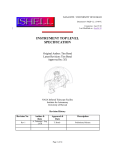
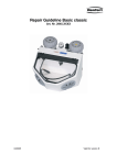
User's Manual
Calibration Unit
PGT120
Wolfgang Warmbier
Untere Gießwiesen 21
D-78247
Hilzingen/Germany
www.warmbier.com
Calibration Unit PGT120 - Operating Instructions
Part No. 7100.PGT120.CU
_
1 Introduction
The Calibration Unit contains resistors to test the limits of the Personal-Grounding-Tester PGT 120.
It works without battery or any external power supply.
To measure the PGT 120 - test voltage you need a DC-voltmeter with an impedance of ≥ 10MΩ.
Notice: Remove all connections from the measuring inputs of the PGT!
Keep the calibration unit at a dry place.
After taking the Calibration Unit from a cold into a warm environment, let it warm up to prevent from
condensation, otherwise it will affect on accuracy.
2 Test voltage measurement
To check the test voltage, set the marked lever of the rotary switch to
and connect:
- the central jack of the calibration unit to the 3 mm snap of the PGT 120
(same symbols
). Use the DK3-socket adaptor which is included.
- The left jack of the calibration unit to the black 4 mm banana socket of the PGT 120
- (wrist strap test, same symbols
).
Use a DC-voltmeter with impedance Ri ≥ 10MΩ, preferably measuring range 2V.
Connect the right jack of the Calibration Unit also to minus-input of the voltmeter and the central
jack of the Calibration Unit to plus-input.
Select the test voltage 30V, 50V and 100V with DIP-switches 4 and 5 and press the left contact
electrode for each measurement.
DIP-switch settings
Switch 4
OFF
OFF
ON
Page 2 / 7
Switch 5
OFF
ON
ON
Test voltage
30 V
50 V
100 V
Edition: April 2008
Calibration Unit PGT120 - Operating Instructions
Part No. 7100.PGT120.CU
_
The test voltage is calculated by reading x 100.
Example: reading = 0,97V ⇒ test voltage = 97,0V
3 Preparation
Starting point for all measurements are the following DIP switch settings.
The calibration is performed with the customers test voltage setting (DIP-switch 4 and 5)
If desired, the test can be repeated with the other available test voltage settings.
ON
OFF
7
6
3
2
1
4 Wrist strap verification
To check the limits of the wrist strap test connect:
- the middle jack of the calibration unit with the 3 mm snap of the PGT 120
(same symbols
). Use the DK3-socket adaptor which is included.
- the left jack of the calibration unit with the black 4 mm banana socket of the PGT 120.
).
(wrist strap test, same symbols
Set the marked lever of the rotary switch in succession to the positions mentioned below. Press the
left contact electrode for each measurement.
750k Lo
750k OK
35M OK
35M Hi
Display LED
Page 3 / 7
Edition: April 2008
Calibration Unit PGT120 - Operating Instructions
Part No. 7100.PGT120.CU
_
5 Footwear test verification (single shoe) - right
To check the limits of the footwear test connect:
- the middle jack of the calibration unit with the 3 mm snap of the PGT 120
(same symbols
). Use the DK3-socket adaptor which is included.
- the left jack of the calibration unit with the red 4 mm socket on the rear side of the PGT 120
(footwear electrode, same symbols ).
Set the marked lever of the rotary switch in succession to the positions mentioned below. Press the
right contact electrode for each measurement.
100k Lo
100k OK
35M OK
35M Hi
Display LED
5.1
DIP-switch settings: Upper limit 70 MΩ
Ω
Switch 3
ON
ON
OFF
7
3
6
2
1
Set the marked lever of the rotary switch in succession to the positions mentioned below. Press the
right contact electrode for each measurement.
70M OK
70M Hi
Display LED
Page 4 / 7
Edition: April 2008
Calibration Unit PGT120 - Operating Instructions
Part No. 7100.PGT120.CU
_
6 Footwear test verification (single shoe) - left
To check the limits of the footwear test connect:
- the middle jack of the calibration unit with the 3 mm snap of the PGT 120
(same symbols
). Use the DK3-socket adaptor which is included.
- the left jack of the calibration unit with the yellow 4 mm socket on the rear side of the PGT 120
(footwear electrode, same symbols ).
6.1
DIP-switch setting for upper limit 35 MΩ
Ω
Switch 3
OFF
ON
OFF
7
6
3
2
1
Set the marked lever of the rotary switch in succession to the positions mentioned below. Press the
right contact electrode for each measurement.
100k Lo
100k OK
35M OK
35M Hi
Display LED
6.2
DIP-switch setting for upper limit 70 MΩ
Ω
Switch 3
ON
ON
OFF
7
3
6
2
1
Set the marked lever of the rotary switch in succession to the positions mentioned below. Press the
right contact electrode for each measurement.
70M OK
70M Hi
Display LED
Page 5 / 7
Edition: April 2008
Calibration Unit PGT120 - Operating Instructions
Part No. 7100.PGT120.CU
_
7 Footwear test in series
To check the limits of the footwear test connect:
- the middle jack of the calibration unit with the red 4 mm socket on the rear side of the PGT 120
- the left jack of the calibration unit with the yellow 4 mm socket on the rear side of the PGT 120
7.1
DIP-switch setting
Switch 6
ON
ON
OFF
7
6
3
2
1
Set the marked lever of the rotary switch in succession to the positions mentioned below. Reset the
instrument after each measurement by disconnecting the left wire:
200k Lo
200k OK
140M OK
140M Hi
Display LED
7.2
DIP-switch setting for upper limit 70 MΩ
Ω
(only for PGT 120 with serial No. 00260 and above) :
Switch 3
OFF
ON
OFF
7
6
3
2
1
Set the marked lever of the rotary switch in succession to the positions mentioned below. Reset the
instrument after each measurement by disconnecting the left wire:
70M OK
70M Hi
Display LED
Page 6 / 7
Edition: April 2008
Calibration Unit PGT120 - Operating Instructions
Part No. 7100.PGT120.CU
_
8 Calibration Unit verification
Recommended calibration cycle: 3 years
To check the resistors, connect a suitable Ohmmeter to the central jack
and the left jack
of the Calibration Unit and set the marked lever of the rotary switch in succession to the
marked positions. The corresponding resistor values and tolerances can be taken from the drawing
below.
Also connect the Ohmmeter to the central
Nominal value must be: 24,4 kΩ ±1%
Page 7 / 7
and right jack of the Calibration Unit.
818,10 kΩ ±1%
31,80 MΩ ±1%
682,20 kΩ ±1%
38,15 MΩ ±1%
217,90 kΩ ±1%
63,65 MΩ ±1%
182,20 kΩ ±1%
76,14 MΩ ±1%
108,90 kΩ ±1%
127,40 MΩ ±1%
90,90 kΩ ±1%
152,54 MΩ ±1%
Edition: April 2008