1
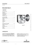
ZAM - SERVIS s. r. o.
KŘIŠŤANOVA 1116/14, 702 00 OSTRAVA 2
USER MANUAL
Continuous conveyor scale
KPV-01
Documentation No.: 206 31
This User Manual contains:
Instructions for assembly, installation, putting into operation, usage, operation, setting, maintenance
and service, disassembly, disposal, and technical conditions
Date of validity: 12.10.2006
Number of pages: 9
User Manual KPV-01 12.10.2006 page 1 of 9
User Manual
This user manual contains instructions for assembly, installation, putting into operation, usage,
operation, setting, maintenance and service, disassembly, disposal, and technical conditions.
All workers carrying out installation, putting into operation, operation, maintenance and service
must be familiarized in a demonstrable way with these instructions for operation. Keep this manual
for further reference.
Content
•
•
•
•
•
•
•
•
•
•
•
Use
Description and function
Installation and assembly
Operating instructions
Maintenance
Service and spare parts
Delivery, transport and storage
Fire safety, ecology, disposal, recycling
Manufacturer and service organization
Related standards, regulations, documents
Technical parameters
2
2
3
5
5
5
5
6
6
6
7
Use
The KPV-01 continuous conveyor scale is used to measure the performance of a conveyor belt
(weight flow) and to calculate total weight. The performance of a conveyor belt is usually measured
in t/h or kg/s. KPV-01 is designed for the measuring of weight of loose and lump materials such as
coal, coke, gravel,…. The scale and the evaluation unit are designed for heavy duty operation and for
areas of methane explosion hazard SNM 1 and 2.
Description and function
The measuring system of the continuous conveyor scale consists of the MSI weighing stand with a
roller whose construction is adapted to the conveyor belt, and the BW100 evaluation unit with KPV01 flameproof enclosure. The weighing stand contains G4-TBSP strain gauges which sense the
longitudinal load of the conveyor belt ml[kg/m]. Another input is the belt speed v[m/s], which is
usually set as a constant, but it can also be measured. From these two values, the performance of the
conveyor belt (or the weight flow) Qm[kg/s, t/h] is calculated by the evaluation unit.
Q m [ kg / s ] = ml [ kg / m ] ⋅ v[ m / s ]
The evaluation unit can display the performance of the conveyor belt [kg/s, t/h], the belt speed [m/s],
the total weight counter (internal totalizer 1 and 2) [t, kg], or the longitudinal load of the belt [kg/m].
The evaluation unit can be programmed so that it switches the output (external totalizer 2) if the total
weight of the material passing reaches a certain level. This output will switch an output relay, whose
contact is conducted to the Ex e terminal block. The unit is factory set so that the relay will switch a
short 0.3s pulse after each ten tonnes. It is possible to set 1:1 switching ratio by changing the function
of KA2 relay.
The KPV-01 electrical and electronic devices are located in an Ex d flameproof enclosure with IP54
protection; there are also Ex ib converters to intrinsically safe levels. The enclosure cover can be
ordered with a sight hole for the display or without a sight hole (standard). The terminal part is of
secured Ex e design. It contains 15 screwless WAGO terminals, 3 M20 plastic bushings and one M40
User Manual KPV-01 12.10.2006 page 2 of 9
bushing. There are two 21mm holes which serve for the connection of protected cables to the strain
gauges, or they may be equipped with M20 bushings. The G4-TBSP strain-gauge sensors of the MSI
weighing stand are simple devices according to ČSN EN 50020.
The power supply of the KPV-01 is led from the Ex e terminals through the switch and fuses to the
transformer, which provides galvanic separation from the supply voltage. From the transformer, the
evaluation unit, the totalizer relay, and the intrinsically safe converter for the sensing of the conveyor
operation switch are fed. The evaluation unit provides the power supply of the strain gauges via the
intrinsically safe converters. The signal from the strain gauges goes back to the evaluation unit again
via the intrinsically safe converters. All intrinsically safe inputs and outputs can be led in one cable.
Fig.1: Block diagram and function of the totalizer
Installation and assembly
1.
Mount the KPV-01 near the weighing stand so that shocks and mechanical strain are
minimized. Unused bushings must be replaced with original fillings.
2.
The installation of the station in explosion-hazard areas must comply with this user manual,
local operating instructions, ČSN EN 50 014, ČSN EN 50 018, ČSN EN 50 020 ed.3, ČSN EN
60 079-0, ČSN EN 60 079-1 and other valid standards and regulations.
3.
The KPV-01 is fastened to a fixed base in the vertical position, using four M8 screws. To
comply with electric shock safety requirements according to ČSN 332000–4–41, the cover of the
station must be earthed by connecting it to the main equipotential bonding. Use the screw-in terminal
User Manual KPV-01 12.10.2006 page 3 of 9
on the side of the flameproof enclosure to connect the earth conductor and the equipotential bonding
conductor.
4.
Connect the 230V/50Hz supply voltage to Ex e terminals 1,2,3 and the totalizer output to Ex e
terminals 4,5 via the M20 and/or M40 bushing. The cable diameter in the M20 bushing can be 613mm. The cable diameter in the M40 bushing can be 17-28mm. The cross section of the connecting
wires can be 0.5-4mm2.
5.
The KPV-01 can be connected only to the MSI weighing stand with G4-TBSP strain gauges.
Connect the protected strain gauge cables to Ex ib terminals 7-13 through the 21mm holes. Connect
the operation switch to Ex ib terminals 14,15 via the M20 bushing. The cable diameter in the M20
bushing can be 6-13mm. The cross section of the connecting wires can be 0.5-2.5mm 2. Each strain
gauge as well as the operation switch must have a separate cable.
6.
The bushings must be properly fastened so that they grip and seal the cables sufficiently. It
must be ensured during the installation and use that the cables are released from strain. No conductor
ends may be placed loosely. There must be a tracking distance and clearance of at least 50mm
between intrinsically safe terminals and terminals which are not intrinsically safe. After the assembly
is finished, all parts of the cover must be properly fixed and sealed. Take particular care when
handling the covers so that the internal components are not damaged.
7.
When closing the device, clean the contact surfaces from dust and apply some lubricant grease
(Mogul K3) on them. The contact surfaces which form an explosion-proof joint must be always free
of any surface treatment, intact, and spread with lubricant grease. Under each screw of the explosionproof enclosure there must be a spring washer. The M10 screws on the cover must be fastened using
the specified torque of 8-10 Nm and the M5 screws using 1-2 Nm torque.
Fig.2: Terminal block X1
User Manual KPV-01 12.10.2006 page 4 of 9
Operating instructions
Except for the power supply, the KPV-01 is an unattended device. The operation of the continuous
conveyor scale depends on the given application. The installation, calibration, adjustment, and
operation of the scale must be done according to the operation manual of the Siemens Milltronics
BW100 unit and the user manual of the MSI weighing stand.
Maintenance
•
Remove dust and impurities from the surface with a dry cloth or a brush; further cleaning
of the surface should be carried out with a cloth dampened in water containing common
detergents or spirit-based cleansers. Check the state of the enclosure and the sealing of the case.
If some dust or dampness gets inside the case, clean and dry the device. Lubricate the device
once or twice every 2 years using Mogul K3 (or a lubricant of similar composition). Before
applying new grease, remove the old layer with a cloth. Keep the contact surfaces of the
individual parts clean and intact.
Service and spare parts
All repairs and spare parts are provided for by the manufacturer, except for the replacement of the
following fuses:
F1,F2
T160mA / 250V, glass fuses 5x20mm
Delivery, transport and storage
•
•
•
•
KPV-01
continuous conveyor scale
• without a sight hole (standard)
• with a sight hole for the display (per order)
The delivery includes
• This User Manual
• Appendix 1: Operation manual for the Siemens Milltronics BW100 unit.
• Declaration of conformity.
• Certificate of quality and completeness of the product.
• The product.
The parts are delivered unpacked.
During transporting all parts it is necessary to minimize possible shocks and impacts. Storage in
dry areas at a temperature of 0 to 40oC in one layer is required.
User Manual KPV-01 12.10.2006 page 5 of 9
Fire safety, ecology, disposal, recycling
•
•
•
Do not expose to open flame; combustion results in the formation of harmful substances.
When correctly used during operation it does not cause any harm to its surroundings and
environment.
After the service life expires, return the product to the manufacturer for disposal. The address is
available in this document.
• Electrical and electronic equipment must not be disposed of as common
municipal waste. The product must be handed over to a relevant collecting point
for proper processing, regeneration and recycling of electrical and electronic
equipment.
• More detailed information about collecting points and recycling of this product
may be required from local authorities, your local municipal waste disposal
company, or your retail agent.
Manufacturer and service organization
ZAM-SERVIS s.r.o. Křišťanova 1116/14, 702 00 Ostrava-Přívoz
tel: 596 135 422
e-mail: [email protected]
Related standards, regulations, documents
LVD:
ČSN 33 2000–4–41 Electrotechnical regulations – Electrical devices – Part 4: Safety –
Chapter 41: Protection against electric shock
ČSN 33 0010
Electrotechnical regulations. Electrical devices. Division and terms
ČSN EN 60529
Protection levels (protection - IP code)
ČSN EN 60 439-1
Low voltage switchboards. Part 1: Type tested and partially type tested
switchboards
EMC:
ČSN EN 60 439-1
Low voltage switchboards. Part 1: Type tested and partially type tested
switchboards
ČSN EN 50014
ČSN EN 50018
ČSN EN 50020 ed.3
ČSN EN 60079-0
Explosion-proof electric devices – General requirements
Explosion-proof electric devices – Flameproof enclosure "d"
Explosion-proof electric devices – Intrinsical safety "i"
Electrical devices for explosive gas atmosphere –
Part 0: General requirements
Electrical devices for explosive gas atmosphere –
Part 1: Flameproof enclosure "d"
Explosive environments – Prevention and explosion protection –
Part 1: Basic terms and methodology
Explosive environments - Prevention and explosion protection –
Part 2: Basic conception and methodology for mines
ATEX:
ČSN EN 60079-1
ČSN EN 1127-1
ČSN EN 1127-2
User Manual KPV-01 12.10.2006 page 6 of 9
Technical parameters
Rated supply voltage, terminals 1,2
Rated power input
Rated fuse current
Max. switched voltage
of the totalizer, terminals 4,5
Max. switched current
Max. switched power
Min. switched voltage
Min. switched current
Cross-section of connected wires,
terminals1-6
Cross-section of connected wires,
terminals 7-15
Cable diameter in the M20 bushing
Cable diameter in the M40 bushing
Distance tensiometer from evaluation
electronics
Temperature range
Relative humidity
Protection
Dimensions (sight hole design)
Weight
Explosion protection
Intrinsically safe parameters
U1, U4 converter
U1 = 9001/01-083-442-101
U4 = 9001/00-083-442-101
U2, U3 converter
9001/02-133-150-101
U5, U6 converter
9002/77-093-040-001
U7 converter
KFA6-SR2-Ex1.W
230VAC, 50Hz, TN-S or IT system
20VA
0.16A
250VAC / 45VDC
5A
100VA / 100W
10V
10mA
0.5mm2 to 4mm2
0.5mm2 to 2.5mm2
6 to 13mm
17 to 28mm
100m
0 to 40 °C
max 95%, no condensation
IP 54
380x510x205mm
40kg
I M2 EEx d e [ib] I
U1 terminals: X1-8
U4 terminals: X1-9
Uo = 8.3V
Io = 442mA
Po = 917.2mW
Lo = 0.5mH
Co = 73µF
U2 terminals: X1-8
U3 terminals: X1-9
Uo = 13.3V
Io = 150mA
Po = 498.8mW
Lo = 7mH
Co = 5.6µF
U5 terminals: X1-10, X1-11
U6 terminals: X1-12, X1-13
Uo = 9.3V
Io = 40mA
Po = 0.09mW
Lo = 87mH
Co = 31µF
U7 terminals: X1-14, X1-15
Uo = 10.6V
Io = 19.1mA
Po = 51mW
Lo = 390mH
Co = 16.2µF
User Manual KPV-01 12.10.2006 page 7 of 9
Fig.3: Line diagram
User Manual KPV-01 12.10.2006 page 8 of 9
Fig.4: Mechanical dimensions (cover without a sight hole-standard; with a sight hole for the display)
Fig.5: The inside of the device
User Manual KPV-01 12.10.2006 page 9 of 9