1
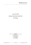
2.4m Observatory Technical Note
Date:
2008 June 9 – version 1.9
Subject:
Obscon User's Manual
Obscon is the main user interface tool for MROST. It provides the following overall functionality:
1.
2.
3.
4.
5.
6.
Observatory circumstances
Target planning
Telescope control
Dome control
Filter wheel control
Weather information
Starting obscon
To run obscon you must have a user account on one of the MROST workstations. If you need an
account, please see the system administrator. Once you are logged in at a system within the
observatory firewall, type the following command into a command window:
obscon -h indi
If you are outside the firewall, start obscon with no arguments and it will prompt for host, ssh
tunneling port, INDI port and login information. This can be given on the command line as well
using the -t command line argument.
Once you are successfully connected to the INDI server for the observatory you will see the main
Obscon window shown in Illustration 1.
Sidereal time
Sun is down
Telescope
Dusk or dawn
Shutter
Moon phase
Moon is up
Fans and louvers
Sun is up
Sun or Moon
Wind direction
Quantitative panel
Illustration 1: Main window
Page 1 of 12
The main window is divided into several panes:
1. Across the top are buttons to open windows devoted to several subsystems; the name of
the facility; Obscon version number; a button to close the dome and mirror cover; and a
panic button that will stop all telescope and dome motion.
2. The Local pane in the upper left is a graphical display showing local time and sun and
moon circumstances for the current day. Clicking on the small question mark in the lower
left brings up a window showing this information at the moment of the click in
quantitative textual form.
3. The Current Pointing pane in the upper center shows current information for the
telescope, including key weather data.
4. The Status pane shows key state information for the dome, telescope, whether a weather
alert is in progress and filter wheel settings.
5. The Sky Dome pane in the upper right is a schematic depiction of the dome as seen
looking from above, with north up and west left. Shown are the location of the dome
shutter opening; status of the fan and louver sets; the sky pointing location of the
telescope; the location of the Sun and/or Moon in the sky; and a dot showing the direction
from which the wind is arriving. Clicking on the small question mark in the lower left
brings up a window showing this information at the moment of the click in quantitative
textual form.
6. Across the bottom is a scrolling region showing Messages from events occurring from the
various subsystem. This list can be erased or hidden as desired. Erasing only effects the
display, all messages are saved forever in the system logs.
Throughout Obscon, lingering the cursor over a field or control (without clicking) will display a
small temporary tool tip message that summarizes the field and gives key information such as
units. Also, Obscon makes extensive use of small colored dots everywhere to indicate specific
state information. These are always one of four colors with the following meaning:
Gray: Idle or unknown
Green: OK or ready
Yellow: Busy or in progress
Red: Alert or problem
Obscon has other command line arguments as well. Follows is the complete list:
-e n
-h h
-p p
-i
-o
-s
-t h s i l
specify number of environment graph samples
specify alternate socket host, default is to create an ssh tunnel
specify alternate INDI port, default is 7624
display inbound INDI messages for debugging
display outbound INDI messages for debugging
use smaller and tighter window layout
specify host, ssh port, INDI port and login for remote tunnel connection
When Obscon exits, it stores the size, location and visibility of each of its windows in a property
file named .obscon in your home directory. It also stores the version of obscon. These windows
are restored when Obscon is started the next time if the versions match. Window information is
stored separately for the case of whether the -s command line argument is used or not.
Page 2 of 12
Next Target
Clicking on Next Target will display the window shown in Illustration 2. The purpose of this
window is to allow you to define and explore the circumstances of the next target for the
telescope without effecting the current telescope operation. In addition to just defining the
target, additional information is displayed to assist in the planning process. This window has no
effect whatsoever on the current telescope operation until or unless the button Track it! is
clicked. Each candidate target it is added to the History list for saving and later reuse.
Illustration 2: Next Target window
This window is divided into several sections, as defined below from top to bottom:
The top section allows you to define a candidate target in three different ways. With the first
option you may enter direct RA and Dec coordinates for a fixed candidate. If a year is entered in
the field labeled @ the coordinates are astrometric for that year; if a 0 is entered, the coordinates
are apparent at the current moment. With the second option you may enter either a catalog
entry1 for the target or its orbital elements in XEphem's edb2 format. When using this means to
specify a target, you must also define the track duration, step size and any desired time offset
The third option is to define an arbitrary track in either RA-Dec or Alt-Az coordinates.
1 Catalogs are located in indi:/usr/local/observatory/catalogs. Asteroids and earth satellites are
updated nightly from MPC and celestrak.com, respectively.
2 See XEphem Reference Manual local hardcopy or online at http://www.xephem.com.
Page 3 of 12
The format of the Track line is perhaps best described from an example:
Track mytarget RADec2K 10:20:30 40:50:00 2454477.62911 10:20:40 40:51:00 2454477.63258
In this example, the track consists of two points. Each point is defined using a triplet consisting
of RA and Dec astrometric coordinates at J2000 and the Julian Date at the moment it is to be
pointed.
The general format is to always start with the keyword Track. This is followed by a name, which
may be any string not containing blanks. This is followed by one of four keywords as described in
Table 1.
Keyword
Meaning
RADec2K
Astrometric RA and Dec @ J2000
RADecEOD
Apparent RA and Dec
AAInside
Alt-Az inside the atmosphere (refracted)
AAOutside
Alt-Az outside the atmosphere (unrefracted)
Table 1: Track keywords
Then follows up to 2000 triplets, consisting of the two coordinates interpreted according to the
keyword and the Julian Date, all separated by spaces. The path is interpolated by a cubic spline.
If the current time is before the first entry, the telescope will go to the first point and wait. If it is
somewhere in the middle of the track it will pick up the track and follow whatever remains. If it is
after the last time, the telescope will slew to the location of the last point and stay there. The
units for all values are degrees except RA which is in hours.
The next section contains command and control functions. Clicking on Check this candidate
will use which ever of the two methods RA-Dec or catalog has been selected to define a target
and attempt to compute its ephemeris information. (Checking is not supported for candidates
defined by the Track method) If successful, a one line description will appear above the button
and additional information as described in subsequent sections, below, will be shown. Clicking
History... will bring up a list of previous candidates and allow the list to be edited, saved and
restored from a disk file. Clicking Track it! will slew the telescope to the candidate defined by
which method is active and begin tracking.
The History files use the extension .ohi, for “Obscon history” or .edb for “ephemeris database”.
The .edb files may only contain lines defining objects in edb format. The .ohi files may contain
lines in any or all of the following formats:
1. A line in the form of an edb object definition
2. A line beginning with the keyword RADec followed by an RA, in hours, a Dec, in degrees,
and an epoch. If the epoch is 0, the RA and Dec are interpreted as apparent, if the epoch
is any other value they are interpreted as astrometric precessed to the given year.
3. A line beginning with the keyword Catalog followed by the name of any entry in the
collection of catalogs on node indi, or the name of any major planet or natural moon.
Page 4 of 12
4. A line beginning with the keyword Track followed by text in the same format as described
for the Track field, above.
Furthermore, lines that begin with # and all blank lines are ignored. Long lines may be continued
any number of times by putting backslash (\) at the end of each partial line.
Below the command buttons is shown a variety of circumstances for the candidate at the current
moment, and information about when it rose (or will rise), transits and sets (or will set). Note
that rise and set times for Earth satellites consider all events, however brief, whereas satellite
events in the time strip and airmass graph (see next) only include events of at least 3 minutes
duration.
The next section down the window is a horizontal time strip in local time centered at midnight.
The green, gray and yellow lines show when the candidate, the moon and the sun are above the
horizon, respectively. The black marker overlaid on the green line shows the moment of transit.
The red marker shows the current local time.
Below the time strip and to the same horizontal time scale is a graph showing the air mass and
altitude of the candidate. This shows at a glance when the candidate is up or down and how high.
At the lower left is an all-sky map with north up and west left. This shows the horizon around the
outer edge, zenith at the center, and lines of 30 and 60 degrees elevation. The candidate is
shown as a green circle and the sun and moon are shown, if they are up.
Page 5 of 12
Telescope
Clicking on Telescope will display the window shown in Illustration 3. The purpose of this window
is to provide direct mechanical control of the telescope. To point the telescope at celestial
targets, use the Next Target window.
Illustration 3: Manual Telescope control
The Manual Telescope window provides the following functions:
1. The top buttons allow you to activate the PMA Pressure system and Fans and open and
close the main mirror cover. Note the system requires the telescope Altitude to be at
least 85 degrees before allowing the PMA to be pressurized.
2. The next two rows of buttons display the current Altitude and Azimuth of the telescope
and allow you to set new values; clicking Set will slew the telescope to the new values.
The arrow keys are a convenient method for adding or subtracting 10 degrees from the
desired set value.
3. The next row of buttons allows you to control where the Instrument Port to which the
tertiary mirror points. The buttons refer to the left and right Nasmyth ports and the four
Bent-Cass ports.
4. The next row displays the secondary M2 Focus position and allows you to enter a new
focus position; clicking Set will move the focus to the new position.
Page 6 of 12
5. The next row of buttons, in conjunction with the diagram below and to the left, allows you
to view and control the rotation angle of the currently selected Nasmyth Interface
Package (NIP). The NIP angle may be set with respect to straight up (raw), or the angle
from the zenith or celestial north as seen looking through the NIP. The diagram shows
each of these reference angles as seen looking into the NIP. To rotate the NIP, select the
desired reference coordinate system; enter a rotation angle either in the text field or using
the convenient buttons which add or subtract 10 degrees; then click Set. The coordinate
system currently being used is indicated by the NIP angle values in bold and underlined.
6. The controls in the Offset section allow you to move the telescope in one of four
directions. The four buttons down the left select the axis of the offset while the Step menu
allows you to select the magnitude of subsequent offsets. Clicking on any of the eight
outer directional pad buttons will inject an additional offset in the given direction and
magnitude. The current net offset is given in the table on the lower right. All offsets may
be removed by clicking on the center pad button labeled Zero. The status light to the left
of Net offset will be green as long as there are currently any non-zero offsets installed.
7. Near the bottom of the Window is a matrix of Status indicators. All indicators should be
green for normal telescope operation. If the Servers status is red, try resetting them by
clicking on Reset Servers. If the Home OK status is red, try rehoming all axes using the
Home All button in the upper right corner of the window.
8. At the lower left corner is a button which will Stop the telescope.
9. If emergency stop or weather alert condition are in effect, these will be indicated by
flashing red text at the bottom center of the window.
Page 7 of 12
Dome
Clicking on Dome will display the window shown in Illustration 4. The purpose of this window is
to offer direct control of the dome and its shutter, fans and louvers.
Illustration 4: Dome control
The dome control window has the following functions:
1. Across the top is displayed the current dome azimuth and rotating velocity. The azimuth is
in the same reference frame as the telescope. The angle and velocity are positive
clockwise as seen looking down from above.
2. The top row of buttons allow you to open or close the Shutter.
3. The next four rows allow you to open and close the Louvers and simultaneously turn on
and off the associated Fans.
4. The next row allows you turn on or off the flood Lights in the dome. These are the same
lights that may be controlled manually using the wall switch at the bottom of the dome
floor stair well or on the Leeson electronics rack on the floor behind the stair well.
5. The next row allows you to Run the dome in either direction at the speed chosen by the
pull down menu (which is degrees per second). The dome will rotate in the given direction
and speed as long as the Run button is depressed.
6. The next row allows you to enter a specific Azimuth for the dome shutter and command it
to rotate to that position. The arrow buttons provide a convenient means to add or
subtract 10 degrees from the target azimuth.
7. The next button offers a one-click means to Close and Park the dome and close all fans
and louvers. The park position is defined in the dome.cfg configuration file.
8. To the right of the Close-and-Park button is a pull down menu containing several useful
Shortcuts for rotating the dome to particular positions without having to know the exact
azimuth angle.
Page 8 of 12
9. Toggling Slave to Telescope on causes the dome shutter to automatically stay in front of
the telescope at all times.
10. The bottom button allows you to Stop the dome at any time. It also disables slave mode if
it is active.
11. If emergency stop or weather alert are in progress, these will be indicated by flashing red
text in the lower portion of the window.
Page 9 of 12
Environment
Click Environment to open a window similar to that shown in Illustration 5 showing weather data
at MRO. The MRO has installed a variety of instruments to measure meteorological parameters
near the telescope which may effect the quality of observations. These data are recorded in log
files at indi:/usr/local/observatory/logs/WX. This window allows you to view the current values of
these parameters, and to view graphs of histories of these parameters spanning a variety of
intervals.
Illustration 5: Environmental conditions
The graph along the top displays any one of the disparate parameters selected in the collections
below. And one item from the first set plus any number of items from the second set may be
displayed simultaneously. The duration of the graph can be set from the choices just below the
graph. The graph updates automatically at intervals commensurate with the interval being
displayed.
If emergency stop or weather alert are in progress, these will be indicated by flashing red text in
at the bottom of the window. If the operator is confident the weather alert will not effect safe
operation of the observatory, the enforcement of the alert may be temporarily overridden by
clicking on the WA Override button. This override will automatically expire after 15 minutes
unless renewed by toggling the button again. The override may also be started before a weather
alert happens if it is important that a weather alert not interrupt some activity, but again the
operator is responsible for ensuring the safety of all equipment.
Page 10 of 12
Filters
Clicking on Filter will display the window shown in illustration 6. The purpose of this window is
to control the optional MRO dual filter wheel that can be placed on the Nasmyth port inline
between the telescope and the instrument. Each wheel can contain 6 filters. The wheels are
arranged so that the light from the telescope passes through any one filter on wheel 1, then
through any filter on wheel 2, then into the instrument. This window allows you to spin each of
the two wheels independently, and assign meaningful names to the filters you have installed.
Illustration 6: Filter wheel window
Before actually using the filter wheel, you should set up the names for your filters. Begin by
editing each field so it gives a short name to each filter position. Be sure to put them in the right
order on each wheel, in accord with the index marks you noted when installing the filters into the
wheels. Then Save them so they can be used later. Later, use Browse to reload the names again
and avoid entering them by hand. Once the name fields all read as desired, click Install to inform
the driver of your chosen names.
Click Initialize to home each filter wheel to a known position. Now you may click any filter on
either wheel at any time and it will be rotated into place in a few seconds. A newly chosen filter is
in place when its status light goes green.
Page 11 of 12
Document History
Version
Date
Author
Changes
1.0
original release
1.1
General editing
1.2
Describe rise/set caveats for earth satellites
1.3
2007 Feb 21 E.C.Downey
Add Camera window
1.4
2007 Mar 3
Update camera snapshot to show temp controls
1.5
2007 Mar 15 E.C.Downey
Describe Binning, Run and Auto save camera features.
1.6
2007 Apr 4
E.C.Downey
Window size/loc/vis persistence; -t arg; page breaks.
1.7
2007 Aug 31 E.C.Downey
Update target, telescope and dome. Remove camera.
1.8
2008 Jan 11
E.C.Downey
Add NextTarget Track
1.9
2008 Jun 9
E.C.Downey
Update Manual Telescope, Dome and Env windows.
Page 12 of 12
E.C.Downey