1
AB300-Series
Automated Filter Wheels
User Manual
(CVI Document # 8-2016-A)
Copyright 1995, CVI Laser Corporation
CVI Laser Corporation
Instruments Group
200 Dorado Place SE - P.O. Box 11308 - Albuquerque - NM -87192 - (505) 296-9541 - Fax (505) 298-9908
NOTICES
Warranty; Hardware:
CVI Laser Corporation warrants this product to be free from defects in material and
workmanship for a period of one year from the date of purchase.
Warranty; Software:
Any software associated with this product is provided "as is" with no warranty, expressed or
implied. 'While it is CVI Laser Corporation's intent to provide error-free useful development
tools, no guarantee is made regarding the accuracy or ultimate usefulness of this material.
Included Software:
Any software distributed with this product is provided free of charge as a service to the customer.
The software is intended to be used as a tool for development and as an example of one possible
method of code implementation. It is not intended to be a "user application."
Software Copyright:
. CVI maintains the copyright on this material, but grants the customer rights to use or modify the
software described herein without obtaining CVI's permission and without the requirement to
reference CVI as the source of material.
Changes:
CVI reserves the right, without prior or further notice, to make changes to any of its products
described or referred to herein to improve reliability, function, or design.
Liability:
CVI accepts no liability for incidental or consequential damages arising from the use of this
product.
CVI Laser Corporation does not recommend the use of its components or software products in
life support applications wherein a malfuoction or failure of the product may directly threaten life
or result in injury.
CVI Laser Corporation
AB300-Series User Manual
Instruments Group
Page I
TABLE OF CONTENTS
1. DESCRIPTION
3
1.1 General Description
3
1.2 Detailed Operation Description
3
2. OPERATION
3
2.1 Mounting
3
2.2 Filter Insta1lation
4
.4
2.3 Conneciions
3. PROGRAMMING
4
3.1 Overview
4
3.2 Commands
3.2.1 Baud
3.2.2 Echo
3.2.3 EEPROM Read
3.2.4 EEPROM Write
3.2.5 Filter
3.2.6 Query Position
3.2.7 Reset
3.2.8 Step Down
3.2.9 Step Up
3.2.iO Zero
:
5
5
6
6
6
7
7
7
8
8
8
:
:
4. OPERATION HINTS
8
5. SPECiFiCATIONS
10
5.1 Mechanical
5.1.1 AB301, Slit'Aperture
5.1.2 AB301, Clear Aperture
5.1.3 AB302
??.:""".,"
10
10
11
12
:
5.2 Eleclrical
5.2.1 RS232 In
5.2.2 Power.
5.2.2.1 AB301
5.2.2.2 AB302
CVI Laser Corporation
AB300-Series User Manual
13
13
13
13
13
Instruments Group
Page 2
5.2.3 Filter Wheel
14
5.3 Cables
5.3.1 Computer to filter wheel RS232
5.3.2 Filter wheel assembly to filter wheel controller
,
14
14
.l5
1. DESCRIPTION
1.1 General Description
The AB300-Series Automated Filter Wheels consist of a motor driven wheel, a computer based
controller, a power supply, and one cable.
Filter wheel control is provided via RS232 from a host computer to the AB300-Series controller.
1.2 Detailed Operation Description
The filter wheel assembly has a stepper motor and a position sensing device. The motor drives
the filter wheel via a belt. The position sensing device allows the filter wheel to determine a
"home" position during a reset. This home position is some number of steps ( the "offset") away
from the filter I position. After home is found, the wheel automatically moves to the filter one
position.
The relative position of filter I is determined by the Filter I Offset, stored in non-volatile
memory. From the filter I position, all other positions are reached by a fixed number of steps and
are not individually programmable. If fine tuning of each position is desired, the Step Up and
Step Down commands may be used. This fine adjusting will not be saved however, and
subsequent moves to each position will require re-adjusting.
The filter wheel controller responds to RS232 commands and requires software to control its
operation. No "manual" mode of operation is provided.
2. OPERATION
2.1 Mounting
Mounting of the wheel itself is via 1/4-20 threaded holes (if provided) located on the sides of the
filter wheel housing.or via a mounting flange (or flanges) on the front and/or back of the housing.
Due to the vast possibilities· of mounting arrangements, custom modification of the filter wheel
housing may be necessary. Modified hardware will not be accepted by CVI for full refund. If
replacement is deemed necessary, CVI will try to re-use modified parts, but is under no
obligation to duplicate customer custom modifications. Mounting hole patterns and flange
dimensions are provided in Specifications; Mechanical.
CVI Laser Corporation
AB300-Series User Manual
Instruments Group
Page 3
2.2 Filter Installation
Access to the filters is provided by removing four screws to remove the cover of the filter wheel
housing.
Filters may be held in place by whatever means suit the customer's application. A popular
method is to use small dabs of silicone RTV on the edge of a filter to "tack" the filter in place.
2.3 Connections
The filter wheel housing to filter wheel controller connection is made via a DB9-F to DB9-M
cable (CVI pn: DKI2AT, provided.) The connection is from the controller port "To Filter
Wheel" to the filter wheel housing.
The host computer to filter wheel controller connection is made via a standard RS232 cable (not
a "Null-Modem" type) to the "RS232 In" port on the filter wheel controller.
The power supply connects to the filter wheel controller at the "Power" jack.
3. PROGRAMMING
3.1 Overview
The AB300-Series controller responds to software commands via the RS232 line. This
communication may come from any device capable of RS232, utilizing any language and
operating system.
The AB300-Series controller is a DCE device and uses the following protocol:
8 Data bits, I Stop bit, No Parity
Baud is user programmable (factory shipped configured at 9600)
Flow control is via hardware handshaking (utilizing CTS and RTS)
Hardware handshaking for the AB300-Series controller is employed as follows:
CTS (from controller to host) signals if the controller is ready to receive a byte over the
RS232 line. If the CTS line is asserted (ie, a positive voltage) the controller is ready to
receive. If a. byte(s) is sent while CTS is deasserted (ie, a negative voltage) the character
may be lost. As the AB300-Series controller has a one character input buffer, multiple
characters or conuRands cannot be received and stored. Since CTS held deasserted while
the filter wheel is executing a command, the reassertion of CTS signals that the command
has completed.
RTS (from host to controller) signals if the host is ready to receive a byte(s) from the
controller. The AB300-Series controller does check this handshaking line and will wait
CVI Laser Corporation
AB300-Series User Manual
Instruments Group
Page 4
indefinitely for RTS to be asserted before sending a character. For this reason, the host
system must ensure RTS is asserted for the filter wheel to work properly.
Proper handling of hardware handshaking is vital to smooth operation. Each programming
language has different methods and defaults for this protocol which must be understood by the
programmer.
The filter wheel controller is designed to be the sole device on an RS232 line. If multiple devices
are desired and com ports are not available, a serial port switch box may be used (contact CVI for
details and suggestions on multi-filter wheel systems.)
3.2 Commands
The communication to and from the controller utilizes bytes (8 bits) sent as characters (the reason
for 8 data bits per character.) Each command consists of one or more bytes (characters) to the
controller. Depending on the command, one or more bytes may be returned by the controller to
return data or signify the end of a command.
Commands should be sent as indicated, without sending terminating characters (for example, do
not send carriage return at the end of each command.) Undesired characters may have an adverse
affect on controller operation.
For the following, a value surrounded by angle brackets ,< >, is the decimal (base 10) value of
byte transmitted. Typical programming practice would be to send and receive these bytes as
ASCII characters, converting them to a decimal value as needed by other programming tasks.
How this is done is dependent on the language used. Refer to the sample programs for examples.
For commands that return a "Status Byte," that byte is interpreted as follows;
Bit
7 (MSB)
6
5
4
3-0
Meaning
o if command accepted
I ifvalue specified = current value
0- value too high, I - value too low (ignore if bit 7 - 0)
o- moving to lower filter, I - moving to higher filter
Not used
The commands and their protocol are described as follows (in alphabetical order);
3.2.1 Baud
To controller:
From controller:
Action:
CVI Laser Corporation
AB300-Series User Manual
f}ec
~
3,4
{;Y --7
<58><Baud Rate Byte>
<Status><24>
Communication baud rate switched to new rate after <24> sent
Instruments Group
Page 5
Baud rate bytes are as follows;
Byte
0
1
2
3
Baud
9600
4800
2400
1200
Byte
4
5
6
7
Baud
600
300
150
75
Note: The controller saves the last selected baud rate and will use that rate at the next
power on or RESET. Therefore, the user must also remember the last baud rate.
Powering the AB300-Series controller off then on will not reset the baud rate.
3.2.2 Echo
tlJAJ
To controller:
From controller:
Action:
<27>
<27>
None
;< 0-')
!Jj
The ECHO command is used to verify communication.
0.,){'J
6(; .~)
3.2.3 EEPROM Read
To controller:
From controller:
Action:
:;iT
<56><Address Byte>
<Data High Byte><Data Low Byte><Status Byte><24>
None
Reads the word (two bytes) value currently stored in: EEPROM non-volatile memory at
the specified address (0 - 15.) The two returned data bytes form a word as follows;
«Data High Byte>
x
256) + <Data Low Byte>
=
Word
3.2.4 EEPROM Write
CAUTIONl Improper or indiscriminate use of this command may impair the
functionality ofthe instrument. Caution and discretion is advised!
To controller:
<59><Address Byte><Data High Byte><Data Low Byte>
<Checksum Byie>
Action:
=~~Data written to EEPROM address
From controller:
<Status Byte><24>
Writes a word (two bytes) to the EEPROM non-volatile memory at the specified address
(0 - 15.) The value of the word is given by
CVI Laser Corporation
AB300-Series User Manual
Instruments Group
Page 6
«Data High Byte> x 256) + <Data Low Byte>
=
Word
The "Checksum Byte" must be correct for the write to be allowed, and is determined by
Address + Data High Byte + Data Low Byte
=
Checksum
where Checksum is a byte long (truncated if necessary) and any carry is ignored. If the
checksum byte is not correct, the command will be IGNORED (no status or <24> will be
sent.)
This command is normally not used except at the factory.
3.2.5 Filter
To controller: <15><Position Byte>
Action:
Filter wheel moves to specified position
From controller:
<Status Byte><24>
Valid positions are I through 5. If position is valid, the wheel turns to the new position.
If invalid, no movement occurs and status byte signals problem.
3.2.6 Query Position
To controller:
From controller:
Action:
D·(
<29>
<Position Byte><Status Byte><24>
None
7
i •
IwF' IJ)
QUERY POSITION will return the present filter position in "Position Byte." (Eg: 1, 2,
3... decimal, not ASCII character "I", "2", "3".)
3.2.7 Reset
To controller:
Action:
From controller:
<255><255>
Filter wheel re-homes and goes to filter position 1.
Nothing'
This command effectively does a power-on reset, resetting the controller board and rehoming the wheel., It is used when there is suspicion the wheel has lost track of where it
physically is (in th:;;-;;~ent of jamming for example.) In normal use this command should
not be needed. It may, however, be used periodically for "just in case" reassurance that
the wheel position is correct.
CVI Laser Corporation
AB300-Series User Manual
Instruments Group
Page 7
Since this command does not return a value, knowing when it completes requires an
alternate strategy. One method is to monitor the CTS line from the filter wheel controller.
It will be deasserted while the RESET is in progress, and asserted when done and ready
for another command (as is standard for RS232 devices utilizing hardware flow control.)
Another way is to send the ECHO command and wait for the echo byte back. If it doesn't
come, repeat the process. This method is preferable only if hardware flow control isn't
available.
3.2.8 Step Down
To controller:
Action:
From controller:
I
<1>
~?
Wheel moves one motor step toward next lower position
<Status Byte><24>
Used to fine adjust the current position. For filter one, it may be used preceding a ZERO
command to set the default filter one position.
3.2.9 Step Up
To controller:
Action:
From controller:
<7>
/
~/ ~
Wheel moves one motor step toward next higher position
<Status Byte><24>
Used to fine adjust the current position. For filter one, it may be used preceding a ZERO
command to set the default filter one position.
3.2.10 Zero
To controller:
Action:
From controller:
i:Yc2(
~,~('
<52>
6';( ~73«(
Current position is saved as filter one default location
<Status Byte><24>
Sets the default filter one position. All other filter positions are derived from this
location. The wheel must be set to filter one position prior to issuing this command.
CAUTION: Failure to select filter one position prior to using this command may cause
erratic or unpredictable results, including failure to operate. Care and discretion is
advised.
4. OPERATION HINTS
Using RESET to close the loop on position: As part of the power on reset the filter wheel fmds
home by sensing a switch closure. This switch sensing is the only feedback the wheel gets
regarding actual physical position. From that point on the wheel is controlled "open loop." If,
CVI Laser Corporation
AB300-Series User Manual
Instruments Group
Page 8
for any reason (e.g.: the wheeljams or becomes disconnected), the wheel looses its position, it
will not be able to tell a problem exists.
It may be desirable or at least reassuring to "close the loop" by having the wheel re-find its home
position. This is done by issuing the RESET command.
Using QUERY position: After power on or the RESET command a filter wheel goes to the
filter one position. All subsequent movements from there are done by issuing FILTER
commands. So, theoretically at least, the controlling software should always know the current
filter position of any filter wheel.
Still, it may be reassuring to query the filter wheel controller to verify what it thinks is the
current position matches what the controlling software thinks. This is done with the QUERY
command. Note, the filter wheel is positioned "open loop" and cannot tell if a malfunction has
prevented the wheel from reaching its desired target. For example, if a wheel became unplugged
from the controller, no error would occur using FILTER commands, and a QUERY would return
the intended position, not the actual filter position (which is long lost.) Only the RESET
command will detect the problem by failing to home..
Fine tuning each position: Only the filter one position has a programmable "fine tuning"
adjustment that is saved. For filter one position only, this is done by using STEP UP and STEP
DOWN, then issuing a ZERO command to store the setting. All other filter positions are a fixed
number of steps from the filter one position.
Fine tuning of each filter position may be accomplished using software techniques. The process
is to go to a filter position, then issue STEP UP/DOWN commands to fine tune the position. The
number of STEP UPIDOWN commands needed must be handled (saved) by the controlling
software. Each time that position is to be recalled, a FILTER # and the appropriate number of
STEPs would be issued.
Note: Adjusting a position using STEPs does not affect the "base" position of subsequent
positions (E.g.: Using 3 step up commands for filter 2 does not make the subsequent filter 3
position off by 3 steps.)
CVI Laser Corporation
AB300-Series User Manual
Instruments Group
Page 9
5. SPECIFICATIONS
5.1 Mechanical
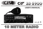
5.1.1 AB301, Slit Aperture
5.500
2.04
4.469
D
0.97
0.353
0.332
#4-40 (2 plcs)
2.187
0.332
0.353
4.375
0.353 .
0.332
4.469
0.586 0.586
Male Flange
CVI po 4-0367
2.187
#6-32 (4 plcs)
o
Female Flange
CVI po 4-0352
o
0.586
INot to Scale I
CVI Laser Corporation
AB300-Series User Manual
Instruments Group
Page 10
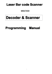
5.1.2 AB301, Clear Aperture
5.500
~
4.343
D
4.375
I~
0.97
)1
2.187
Thin cover
#6-32 (2 plcs)
See below for
hole pattern
Threaded Flange"
CVI pn 0-2010
4.343
0.49
)1
0.491
2.187
Thick cover
0.491
o --t-",
#6-32 (2 pies)
0.491
INot to Scale
* Threaded flange is Thorlabs
CVI Laser Corporation
AB300-Series User Manual
I
1" tube compatible.
Instruments Group
Page 11
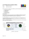
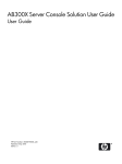
5.1.3 AB302
725
Threaded Flange.
CVI pn 02009
-
4.470
~
3.625
10.780
I
'\
2.780
'1
a
1.625
~
a
+
2.470
~
0.59 4
a -
I
3. 750
a
I-
~EJ
a
7.50
/
-....J
f--
!Not to Scale
I
~
(
2.85
3.23
• Threaded flange is Thorlabs 2" tube compatible.
CVI Laser Corporation
AB300-Series User Manual
Instruments Group
Page 12
)1
5.2 Electrical
5.2.1 RS232 In
DB9 pin
2
3
5
7
8
Signal
~xD
TxD
GND
RTS
CTS
Direction
From controller to computer
From computer to controller
Signal Ground
From computer to controller
From controller to computer
The AB300-Series controller RS232 port (a DCE device) should be connected to a computer
(DTE device) via a standard "straight through" cable (not a null modem type.) Connector is
munbered.
5.2.2 Power
5.2.2.1 AB301
Tip: +5VDC
Shaft: Return
5.2.2.2 AB302
Center: +12 VDC
Outside: Return
r
)
CVI Laser Corporation
AB300-Series User Manual
Instruments Group
Page 13
5.2.3 Filter Wheel
Pin out applies at wheel assembly and controller. Connectors are numbered.
DB9 Pin
Function
I
2
3
4
5
6
7
8
9
Motor Coil; Blue
Motor Coil; Black
Motor Coil; Red
Motor Coil; Yellow
Motor Coil; White
Motor Coil; Green
Home Contact
Home Contact
N/C
5.3 Cables
5.3.1 Computer to filter wheel RS232
RS232: DB9-F to DB9-M (CYlpn DK12AT), for 9 pin serial DTE to AB300-Series
From DB9-F pin
1
2
To DB9-M pin
1
2
3
4
5
3
4
5
6
7
8
9
6
7
8
9
CVI Laser Corporation
AB300-Series User Manual
Instruments Group
Page 14
RS232:DB25-F to DB9-M, for 25 pin serial DTE to AB300-Series
From DB25-F
pin
To DB9-M pin
8
I
2
3
3
2
20
7
6
4
5
22
4
5
6
7
8
9
5.3.2 Filter wheel assembly to filter wheel controller
From DB9-F pin
1
2
3
To DB9-M pin
1
2
3
4
4
5
6
7
8
9
5
6
7
8
9
It is recommended this cable use 26 AWG or larger wire, be shielded, and not exceed 12 feet in
length.
CVI Laser Corporation
AB300-Series User Manual
Instruments Group
Page 15