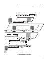
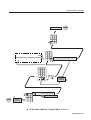
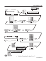
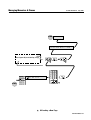
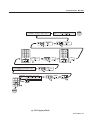
1
JANDS EVENT
© Jands Electronics May 1995
Event V3
Operating Manual
Event V3 Manual 1
Introduction
Table of Contents
JANDS, one of the world’s leading lighting console manufacturers, now offers the
EVENT PLUS series of control consoles. Equipped with all the outstanding
features of the original Event, the EVENT PLUS offers many new functions and
features. Available in two configurations: 48 and 60 channels, each with 24 Assign
masters and 2 Presets, the EVENT PLUS features a “first” for JANDS - single preset
operation. In today’s lighting rigs there is an increasing emphasis on moving lights
and colour scrollers both of which quickly use up available channels. The EVENT
PLUS’s ability to operate as a single preset board means that it can offer up to 120
channels for programming and playback.
Recording on the EVENT PLUS has been simplified with the addition of One
Touch Recording, simply hold the Record button and press an Assign master flash
button to store a memory to that Assign fader. To make labelling and the addition
of fade times easier, Memories that have been recorded are tagged with an “r” in the
Memory menu.
The EVENT PLUS Page consists of 20 Memories and 1 Chase, the remaining
3 Assign faders are set to control 2 fixed Memories and 1 fixed Chase. However it
is possible to edit the standard Page setup or to Assign any combination of crossfade
Stacks, Chases or Memories to the 24 Assign faders. A further enhancement to the
Assign master section is the ability to use the Hold master as a submaster controlling
all 24 Assign faders.
Output from the console is available via a standard DMX-512 socket or through
optional analogue Socapex connectors, using either method it’s possible to use the
onboard softpatch to create up to 3 different channel to dimmer patching tables.
The EVENT PLUS is a further extension of the committment to ongoing
development which makes JANDS lighting consoles the most exciting and innovative
products available today.
2 Event V3 Manual
Table of Contents
© Jands Electronics May 1995
General Description _____________________________
1.00
General Description Of Major Parts .................................................. 10
2.00
How The Event Stores Information.................................................... 11
3.00
The Event Menu System ...................................................................... 13
Getting Started _________________________________
4.00
Hardware Setup ...................................................................................
Connecting Power ..................................................................................
Connecting Desklights ...........................................................................
Connecting a VDU .................................................................................
Connecting MIDI Device .......................................................................
Connecting a Slave Console...................................................................
Turning the Power On ............................................................................
16
17
17
15
17
17
17
5.00
Software Setup ......................................................................................
Setting the Number of Console Channels ..............................................
- To Increase the Number of Channels Available On the Consoles ....
Patch .......................................................................................................
- To Patch Dimmers to the Consoles ...................................................
- Patching Multiple Dimmers to a Consoles ........................................
- Storing Changes Made in Patch ........................................................
Labelling Patch.......................................................................................
18
18
18
20
20
20
20
22
6.00
Manual Controls................................................................................... 23
The Presets / Presets Faders / Flash Buttons .......................................... 23
Creating Memories & Chases______________________
7.00
Memories ...............................................................................................
Recording Memories ..............................................................................
- METHOD 1: Record and Point .........................................................
- METHOD 2: Using the Menu ............................................................
Labelling a Memories ............................................................................
Playing back a Memory .........................................................................
Editing a Memory ..................................................................................
- METHOD 1: Record and Point .........................................................
- METHOD 2: Using the Menu ............................................................
26
26
28
30
30
31
32
32
34
Event V3 Manual 3
Table of Contents
8.00
Chases .................................................................................................... 36
Recording a Chase-Using the Menu ...................................................... 36
Lablling a Chase ..................................................................................... 38
Setting the Chase Direction .................................................................... 39
Setting the Chase Speed ......................................................................... 40
Adding Attack / Decay to the Chase ...................................................... 41
Adding a Dipless Crossfade Between Steps (X) .................................... 42
Playing Back a Chase ............................................................................. 43
Recall a Chase - Introduction to Assign ................................................. 44
- METHOD 1: Change Page................................................................ 44
- METHOD 2: Assign the Chase .......................................................... 46
Editing a Chase ...................................................................................... 48
- METHOD 1: Using the Menu ............................................................ 48
- METHOD 2: Using Assign Flash Button .......................................... 50
Deleting a Step ....................................................................................... 52
Adding a Step ......................................................................................... 53
Recording Changes Made in Edit .......................................................... 53
Managing Memories & Chases ____________________
9.00
Pages ...................................................................................................... 56
Page Make-Up ........................................................................................ 56
Loading a New Page .............................................................................. 56
Freeze ..................................................................................................... 58
Labelling a Page ..................................................................................... 60
10.00 Assign .................................................................................................... 61
Assign Memory ...................................................................................... 62
Assign Chase .......................................................................................... 64
Assign Stack ........................................................................................... 66
Special Feature - Assign Edit ................................................................. 66
11.00 File .........................................................................................................
Saving a File ...........................................................................................
Loading a File ........................................................................................
Labelling a File ......................................................................................
68
68
68
70
12.00 Stacks ..................................................................................................... 71
Control File ............................................................................................ 71
- NEXT Fields ...................................................................................... 71
- INFADE / OUTFDE (Outfade) Fields............................................... 71
- Delay Field ........................................................................................ 72
Changing the NEXT Field ..................................................................... 72
- Changing the NEXT Field - Memory ................................................. 72
4 Event V3 Manual
© Jands Electronics May 1995
- Changing the NEXT Field - Chase .................................................... 74
Infade/Outfade - Adding Fade Times .................................................... 76
- Adding Fade Times to a Memory ...................................................... 76
- Adding Fade Times to a Chase .......................................................... 78
Adding Delay Time ................................................................................ 80
- Adding Delay Times to a Memory ..................................................... 80
- Adding Delay Times to a Chase ........................................................ 82
Control Functions - Playback______________________
13.00 Playback ................................................................................................ 86
Controls .................................................................................................. 86
- Preset Faders ..................................................................................... 86
- Assign Masters ................................................................................... 86
- Flash Buttons ..................................................................................... 86
- LCD Windows .................................................................................... 87
Controlling Memories ............................................................................ 87
- Assign Masters ................................................................................... 87
- LCD Windows .................................................................................... 87
Controlling Chases ................................................................................. 87
- Assign Masters ................................................................................... 87
- Flash Buttons ..................................................................................... 88
- To Change the Operation of the Chase Flash Button ....................... 88
- LCD Windows .................................................................................... 88
Controlling Stacks .................................................................................. 88
- METHOD 1: Using the Assign Stack Menu ...................................... 89
- METHOD 2: Using the Stack Menu/Assign Faders .......................... 89
Playback of a Stack ................................................................................ 89
- Stack Controls.................................................................................... 89
- Assign Master Faders ........................................................................ 90
- Go / Back Buttons .............................................................................. 90
- LCD Windows .................................................................................... 90
Clear Output From a Stack ..................................................................... 90
Taking Manual Control of a Fade .......................................................... 90
- Taking Manual Control Fade When a Fade is Not Running ............. 91
Altering the Playback Order................................................................... 91
The SMaster / Hold Master .................................................................... 92
- To Set the Operation of the Hold / SMaster ...................................... 92
- SMaster as Assign Faders Master ..................................................... 94
- SMaster as Hold Master .................................................................... 94
- SMaster as Manual Crossfade Master .............................................. 94
- SMaster as Memory / Chase Control ................................................ 94
14.00 Overall Master Controls ...................................................................... 95
P1 and P2 Faders .................................................................................... 95
- Reversing the P2 Master fader .......................................................... 96
Add / Solo Master Switch ...................................................................... 98
DBO Switch ........................................................................................... 98
- To Chang the Operation of the DBO Switch ..................................... 98
Add / Solo Fader .................................................................................... 99
Grand Master Fader................................................................................ 99
Rate Control ........................................................................................... 99
Event V3 Manual 5
Table of Contents
Advanced Features ______________________________
15.00 Advanced Control .............................................................................. 102
Build ..................................................................................................... 102
To see the changes in a Build Memory ................................................ 103
Other Build Menu Features .................................................................. 104
Edit Memory ........................................................................................ 105
- Restoring theatrically-Using Edit Nemory Menu .............................. 105
Edit Page .............................................................................................. 106
- Changing the Make-up of a Page ...................................................... 106
Edit File ................................................................................................ 109
- Changing the Default File Settings .................................................... 109
- Restoring the Factory Setting for File ............................................... 109
16.00 Restricting Access to Various Menus and Controls ........................ 110
17.00 Function Keys ..................................................................................... 111
To Record a Function Key ................................................................... 112
To Play Back a Function Key .............................................................. 112
18.00 Advanced Channel Control ............................................................... 114
Setting Channels to Ignore Crossfade Timing ..................................... 114
- To Set Channels to Ignore Timing ..................................................... 114
Setting Channels to Always Have a Background Intensity-Preheat .... 116
- To set Channels to Preheat the Filament........................................... 116
Setting Channels to Ignore Flash button Solo Operation ..................... 118
19.00 Advanced Desk Options ..................................................................... 120
Setting Default Infade and Outfade Times........................................... 120
Changing the Increment Between Memories When Recording ........... 122
Turning the Help Screen On and Off ................................................... 122
20.00 Using the MCard - Option ................................................................. 123
To Open the MCard Menu ................................................................... 123
To Save the Information Recorded in the Event .................................. 123
Loading From the MCard..................................................................... 123
21.00 Clearing Memories Chases and Patches .......................................... 124
Clearing Memories ............................................................................... 124
Clearing a Stack ................................................................................... 126
Clearing Chases .................................................................................... 126
Clearing a Patch ................................................................................... 128
22.00 Copying Memories Chases and Patches ........................................... 130
Copying a Memory .............................................................................. 130
Copying a Chase .................................................................................. 132
Copying a Patch ................................................................................... 132
6 Event V3 Manual
© Jands Electronics May 1995
23.00 Resetting the Console ......................................................................... 136
To reset the Console ............................................................................. 136
24.00 Connecting a Slave Console............................................................... 138
To Set an Event Console as a Master ................................................... 138
To Set an Event Console as a Slave ..................................................... 138
25.00 Event LCD Displays ........................................................................... 139
LCD Control......................................................................................... 139
26.00 Setting the Intensity of the Desklights .............................................. 140
27.00 Using MIDI to Control the Event ..................................................... 141
To Select the MIDI Menu .................................................................... 141
28.00 Connecting an External Monitor to the Event - Option ................. 142
29.00 Analogue Output - Option ................................................................. 143
30.00 Floppy Disc Drive - Option................................................................ 144
General ...........................................................
31.00 Maintenance........................................................................................ 146
32.00 Service ................................................................................................. 147
33.00 Battery Replacement .......................................................................... 148
Appendix A.......................................................
33.00 Event 24 Output Menu Structure ..................................................... 150
Appendix B.........
34.00 Pin Assignments ................................................................................. 152
DMX Connector Wiring ...................................................................... 152
Midi Connector Wiring ........................................................................ 152
Desklight Connector Wiring ................................................................ 152
Desk Link Cable Wiring ...................................................................... 153
Power Connector Wiring...................................................................... 153
Midi Note Table ................................................................................... 153
Event V3 Manual 7
Table of Contents
8 Event V3 Manual
© Jands Electronics July 1995
General
Description
Event V3 Manual 9
General Description
1.00 General Description of Major Parts
1.10 Manual Control Section
☞
Diagram 1A
This section is used to control the level of individual desk channels. There are 2
faders (Preset 1 and Preset 2) and a Flash button with an inbuilt level indicator per
channel. There is also a writing strip below the Flash buttons.
1.20 Assign Master Section
▲ 1A Manual control section
☞
Diagram 1B
This section is used to control the playback of Memories, Chases and crossfade
Stacks. There are either 12 or 24 Assign Masters (depending on the desk type) and
a corresponding number of Flash buttons. The LCDs located above the Assign
Master faders display labels for the items being controlled.
1.30 Master Section
▲ 1B Assign master section
☞
Diagram 1C
This section includes the Grand Master fader and DBO button, Flash Master fader
and selector switch, Preset Master faders, and a Chase rate control. There is also a
Hold / SMaster fader and switch.
1.40 Menu Control Section
▲ 1C Master section
☞
Diagram 1D
The Event menu system is used to enter and modify settings for Memories, Chases,
Stacks, Pages and Files while recording and during playback. It is also used to
configure the various setup options.
1.50 Back Panel
☞
Diagram 1E
All power and control connections are made on the rear of the console. This is also
where option panels are fitted. Possible options include:
* 60 way analogue output option
* 30 way analogue output extender option
▲ 1D Menu control section
* MCard option
* MCard/VDU (Mono, CGA, EGA)
* MCard/VDU (VGA)
* Floppy disk drive
▲ 1E Back panel showing M
card option fitted
10 Event V3 Manual
NOTE:
The keyboard and RS 232 Connections on the rear of the Event Plus are for factory
use only.
© Jands Electronics July 1995
2.00 How the Event Stores Information
☞
Diagram 2A
The information required to control stage lighting instruments is recorded into two
basic units: Memories and Chases.
These basic units can be further organised and grouped to suit a particular
performance or show.
-
A Page consists of a factory-defined group of Memories and Chases.
-
A File consists of a user-defined group of Memories, Chases and Stacks.
-
A Stack consists of a sequence of Memories and Chases.
The way these items relate to each other can be seen in diagram 2A.
Page
M 10
M 11
M 12
M 13
M 15
9
C1
C 100
Event Plus only
M 29
(Event Plus)
Memories and Chases in sequential set of memories plus two Chases and two undefined faders
on Event Plus
File
M 10
M 11
C 10
M 99
M200 M201
C 1
C 10
C 11
User-defined set of memories and Chases
Stack
M 10
M 10
M 10
M 10
M 10
M
C 10
M 10
M 10
M 10
M 10
M 10
M 10
M
C 10
M 10
M 10
M 10
Memories and Chases for
M 10
M 10
playback in a user-defined order
M 10
M 10
▲ 2A Basic organisation of memories and chases
Event V3 Manual 11
General Description
2.10 Memories
A Memory consists of level settings for all of the lights, colour scrollers etc.
connected to the console. These level settings range from 0% (when the light is not
included in the Memory) through to 100%.
Memories include a label that is displayed on the LCD above the Assign Master
faders controlling it, and can also include timing information to control fade rates.
Memories can be assigned one at a time to the Assign Master faders or to a Stack
(i.e. a sequence of Memories) that in turn can be assigned to a pair of faders.
2.20 Chases
A Chase consists of one or more Steps, each of which contain level settings for all
of the lights, colour scrollers etc. connected to the console. These level settings
range from 0% (when the light is not included in the Chases) through to 100%.
Chases include a label along with speed, direction and fade information, and can
also include timing information to control the fade rate.
Chases can be assigned one at a time to the Assign Master faders or, as part of a
Stack, to a pair of Assign Master faders.
2.30 Pages
A Page consists of a factory-defined group of Memories and Chases that are loaded
to the Assign Master faders. Changing Pages completely replaces the previous set
of Memories and Chases. Many operators allocate a Page for each song or act of
their show.
2.40 Files
A File is like a Page but it can be customised to include any combination of
Memories, Chases and even Stacks. A File is created by loading the items you want
onto the Assign Master faders and then saving these settings as a File.
2.50 Stacks
Memories (and Chases) can be automatically crossfaded in a sequence called a
Stack. Initially all Memories (and Chases) are linked together in numeric order Memory 1 is followed by Memory 2 and so on to Memory 999. This is followed by
Chase 1 which is followed by Chase 2 and so on to Chase 999.
However this order can be changed so that Memories follow a non-numeric order.
For example Memory 10 might be followed by Memory 20 which is followed by
Memory 25.
Stacks can also start and stop anywhere within the available range of Memory
numbers. For example you might use Memories 100 through 120 as one Stack and
Memories 150 through 200 as another.
Fortunately it’s not necessary to decide which Memories you want to include in a
Stack when you are first recording. The links that join Memories and Chases can
be changed at any time. Likewise, crossfade timing information can be added or
altered after a Memory is recorded.
(The use of Stacks is explained more fully in section 12.00).
12 Event V3 Manual
© Jands Electronics July 1995
7
8
MEMORY
4
9
EDIT
5
PAGE
1
BUILD
CHASE
6
ASSIGN
FILE
2
3
CLEAR
STACK
0
EXIT
SETUP
RECORD
▲ 3A Function keypad
Mo d i f y s t a nd a r d con s o l e s e t t i n g s
c u s t om i se co n t r o l s & o u t p u t s .
▲ 3B Typical help message
3.00 The Event Menu System
☞ Diagram 3A, 3B
All recording, editing, setup and other console functions are controlled via a series
of menus. The function keypad along with cursor and value buttons provide the
means of opening the menus and entering information.
Since the Event menus are used in many operations it's worth taking some time to
familiarise yourself with what the various buttons do and some of the shortcuts that
are available.
Whenever one of the ten function buttons : Setup, Build, Clear, Stack, Page, Assign,
File, Memory, Edit or Chase is pressed, a menu opens up in the LCD nearest to the
function buttons and a help message is displayed in the adjacent LCD .
Some functions like Edit and Assign which are used in conjunction with others use
a second button press to select the appropriate menu (i.e. Edit Memory or Edit
Chase). Others such as Setup and Clear provide a number of sub-menus to choose
from.
3.10 Menu Fields
S ET D E SK P t c h C t r l U t i l P r e f Mc r d
UP + t o + t o + t o + t o + t o + t o
▲ 3C Typical menu field
☞
Diagram 3C
Each menu consists of a number of fields. The name of the field appears on the top
line of the display and the setting or value for that field appears underneath it.
Sometimes a field is used to lead to another menu; in this case, the bottom line shows
[ + t o ] which means “Press the 1 (On) button to open another menu”.
NOTE:
As the cursor is moved, the field the cursor is in changes to UPPERCASE.
3.20 Cursor Buttons
☞
▲ 3D Cursor buttons
Diagram 3D
The left arrow and right arrow buttons are used to move the cursor between the
various fields in each menu.
3.30 1 (On) and 2 (Off) Buttons
☞
OFF
ON
▲ 3E 1 (On) and 2 (Off) Buttons
Diagram 3E
The 1 (On) and 2 (Off) Buttons are used to change values. The 1 (On) button will
either increase a value or change a setting from Off to On or change a letter/character
on a label. Likewise, the 2 (Off) button will decrease values or change a setting
from On to Off. These buttons are also used in a few menus to toggle between
several choices, e.g. Setting a Chase to forward or reverse.
The buttons operate in three ways:* Press: The value increases by 1 with the 1 (On) button or decreases by 1
with the 2 (Off) button.
* Press and Hold: The value scrolls up with the 1 (On) button, or down with
the 2 (Off) button.
* Double Press: The value snaps to maximum with the 1 (On) button or to
minimum with the 2 (Off) button. It may take a couple of attempts to double
press at a fast enough speed to see this work.
Event V3 Manual 13
General Description
3.40 Entering Numbers Directly to Fields
Once a menu has been opened the function buttons change to a numeric keypad.
Numbers can be entered directly into menu fields such as Page number, Memory
number and so on.
3.50 Entering Labels
Diagram 3F, 3G, 3H
PRESET
FLASH
▲ 3F Preset Flash button
The Memory, Chase, Page, File and Patch menus all have a Label field. The section
circled in Diagram 3H shows the Memory menu with the Label field highlighted
(the other menus all have the Label field in the same position). The Event
automatically supplies a label for each field (in the diagram shown as M10) but the
Preset/Assign Flash buttons can be used to type a label of your choice. Below each
Flash button there is a character marking.
Example:
ASSIGN
FLASH
▲ 3G Assign Flash button
M E M : _ __ _
M 10 M 1 0
I n f a d e Ou t f d e
0 : 0 0 0 0 : 0 0 0 Mo r e
▲ 3H Memory Menu
•
Open the Memory menu and use the right arrow button to move the cursor
to the first character position of the label field.
•
Type BLUE WASH or something similar. If you make a mistake just use the
cursor buttons to move back and type over the incorrect character. The
square box marking below the third (fifth on Event Plus) Assign Master
Flash button represents a space. You can also use the numeric keypad
to type numbers.
3.60 Exit Button
7
8
MEMORY
5
4
PAGE
1
Diagram 3I
9
CHASE
EDIT
6
ASSIGN
FILE
2
3
CLEAR
STACK
BUILD
The Exit button is used to back out of the menu system. If a top level menu is open,
pressing Exit closes the menu system. If a nested menu is open pressing the Exit
button makes the display return to the previous (higher level) menu.
0
EXIT
SETUP
RECORD
▲ 3I Exit button
If no menu is open the Exit button can be used to show the Event software version
number.
3.70 Record Button
7
8
MEMORY
EDIT
5
4
PAGE
1
BUILD
Diagram 3J
9
CHASE
6
ASSIGN
FILE
2
3
CLEAR
STACK
0
EXIT
SETUP
RECORD
▲ 3J Record button
14 Event V3 Manual
When a menu is open the Record button is used to save new or modified intensity
settings.
If no menu is open the Record button can be used to change the LCD window from
showing Memory and Chase labels to showing Memory and Chase numbers. This
feature is useful if you have given names to Memories and Chases and need to know
what number they were, or need to see the steps of a Chase sequencing.
© Jands Electronics July 1995
Getting Started
Event V3 Manual 15
Getting Started
4.00
Hardware Setup
4.10 Connecting Power
Plug the socket end of the power cord into the IEC power receptacle located on the
rear face of the Event. The other end of the power cord should be plugged into a
3-pin grounded outlet. It is important that the Event is electrically grounded; if in
doubt, contact a licensed electrician.
4.20 Connecting the Output to a Dimmer
Event provides two methods of connection to dimmer systems. The DMX output
is standard on all consoles. Optional Socapex output panels can also be fitted to the
console to provide 0 - 10V wire-per-channel analogue outputs.
METHOD 1. DMX-512 Output
Connect from the console's DMX output to the DMX input on the dimmer rack.
Check the dimmer instruction manual for details on selecting DMX channels
and looping the DMX line to other dimmer racks.
Up to 512 dimmer channels can be controlled in this way.
METHOD 2. Analogue Outputs (Option)
Connect from the console's Socapex outputs to the dimmer rack input. Up to
eight Socapex connectors can be fitted to a console to provide up to 240 channels
of dimmer control.
16 Event V3 Manual
© Jands Electronics July 1995
4.30
Connecting Desklights
Desklights are available as an optional accessory. Only 12V Littlite or compatible
desklights with 3-pin Cannon XLR type connectors should be used (for wiring see
Appendix B).
4.40
Connecting a VDU
Connect from any Monochrome, CGA, EGA or VGA monitor to the connector on
the option panel. Two video output options are available to suit the above range of
monitors (for wiring see Appendix B).
4.50
Connecting a MIDI Device
The Event console is equipped with a MIDI input (there is no through connector).
Use a standard MIDI cable to conect from the MIDI device to the MIDI In connector
on the backpanel (for wiring see Appendix B).
4.60
Connecting a Slave Console
Any Jands Stage 12, ESP II or Event console can be slaved to the Event.
Connect from the DMX output of the slave console to the MIDI input of the main
console. This cable should be wired as detailed (for wiring see Appendix B).
4.70
Turning the Power On
Once all connections have been made the console can be turned on using the mains
power switch located next to the power lead input.
Event V3 Manual 17
Getting Started
5.00 Software Setup
5.10 Setting the Number of Console Channels
5.11 To increase the number of channels available on the console
☞ Diagram 5A
One of the most powerful features of the Event is its ability to work as a single preset
board outputting double the number of channels normally available. In applications
where colour scrollers or moving lights are being controlled this feature greatly
extends the usefulness of the console. An Event 24, for instance could control 48
colour scrollers.
NOTE:
WIDE should be turned on before any Memories or Chases have been recorded.
When WIDE is turned on the number of available Memories is reduced.
Once a console has been set to WIDE the Preset 2 faders are used to control the
higher numbered channels. For example, on an Event 48 the Preset 2 faders would
control channels 49 to 96. The Preset 2 Master fader is disabled.
When Wide mode is on an indicator appears at the far right end of the right LCD
window. W1 indicates the desk is in Wide mode with a single preset, W2 indicates
the desk is in Wide mode with dual presets.
1
Press the Setup button to open the Setup menu.
2
Move the cursor to the DESK field and press the 1 (On) button to open the
Set Desk menu.
3
Move the cursor to the WIDE field and press the 1 (On) button to open the
Set Desk Wide menu.
4
In the Set Desk Wide menu move the cursor to the WIDE field and press the
1 (On) button to change the field to On.
5
Move the cursor to the CHANS field - this field will have automatically
changed to double the number of channels [i.e. a 60 channel console will
have changed to 120. Type in any number of channels to a maximum of 252
(120 on Event)].
NOTE:
18 Event V3 Manual
If more than double the number of channels are selected in step 5 you will need
a slave console to control the extra channels (see Section 24.00).
6
Move the cursor to the PSETS field and change this field to Single to allow
all the Preset faders on the console to be used as a single preset. On an Event
60 this means you will have 120 console channels with the top preset controlling channels 1-60 and the bottom preset controlling channels 61 - 120.
7
Move the cursor to the CONFIRM field. If all the settings are correct press
the 1 (On) button to confirm the changes.
8
Press Exit to close the Set Desk Wide menu.
9
Press Exit once more to close the Setup menu completely.
© Jands Electronics July 1995
END
7
[STANDARD SCREEN]
PAGE
6
ASSIGN
2
1
CHASE
EDIT
5
4
BUILD
23
8 & 9
9
8
MEMORY
FILE
3
CLEAR
SET DE SK P t c h C t r I
U P 6t o 1t o 1t o
STACK
0
EXIT
Se t
Des k
SETUP
RECORD
MODE W i d e
Re c 1 t o
L i nk
1t o
Ut i I
1t o
P r e t Mc r d
1t o 1t o
D i sp l ay Ex t n
1t o
1t o
CON F IR M
No
7
PS ETS
S i ng l e
PS ETS
Du a l
6
7
8
MEMORY
4
EDIT
5
PAGE
1
ASSIGN
2
BUILD
CLEAR
9
CHASE
6
FILE
3
STACK
0
EXIT
CHANS
120
SETUP
RECORD
CHANS
xxx
OR
5
Se t
Wi de
W I DE
Of f
Ch a n s
60
W I DE
On
Ps e t s Con f i r m
No
Du a l
Ch a n s
120
4
Se t
Des k
WI DE
6t o
MODE W i d e L i nk D i s p l a y E x t n
Re c 1 t o 1 t o
1t o
1t o
3
7
8
MEMORY
EDIT
5
4
PAGE
BUILD
CHASE
CLEAR
SET DE SK P t c h C t r I U t i I P r e t Mc r d
U P 6t o 1t o 1t o 1t o 1t o 1t o
2
6
ASSIGN
2
1
9
FILE
3
STACK
0
EXIT
SETUP
RECORD
1
START
5A Setting the Number of Console Channels
Event V3 Manual 19
▼
Getting Started
5.20 Patch
P T _ _ _ _ C h # D i m : A t D i m: A t D i m : A t
1 M 10
1 1 F F NC F F N C F F
5B Patch menu
☞ Diagram 5B
The Event will control up to 512 dimmer channels via the DMX output or 240
channels via the optional analogue output panels. The Patch menu allows these
dimmer channels to be patched at any level to the console channels. There are three
Patch tables available.
▼
Normally when you turn the console on Channel 1 will be patched to dimmer
channel 1, Channel 2 will be patched to dimmer channel 2 and so on for all the
console channels. To change this you use the Patch menu.
TIP:
It is possible, for example, to set one Patch which includes all dimmers for the
main act, and a different Patch which might not include all dimmers for the
support act. Similarly if a light was knocked out of focus during the show the
Patch could be used to reduce the level of its dimmer to 0 so the light would not
come on at any time.
Changing the Patch number will make the new Patch active immediately - be
careful about making any changes during a show.
5.21
To Patch Dimmers to the Console
☞ Diagram 5C
1
Press the Setup button to open the Setup menu.
2
Move the cursor to the PTCH field and press the 1 (On) button to open the
Patch menu.
3
Press the 1 (On) button or Keypad to change the Patch number in PT field
(there are 3 Patches available - 1, 2 and 3).
4
Move the cursor to the CH# field and set a console channel number (i.e. 1).
NOTE:
Patch tables 1d/2d/3d display Patches 1/2/3 in reverse, i.e. a dimmer number
is specified and the control channel is shown.
5
Move the cursor to the DIM: field and set a dimmer number (i.e. 1).
6
Move the cursor to the AT field and set the intensity (normally FF or 100%).
5.22
7
5.23
Patching Multiple Dimmers to a Channel
The CH#, DIM: and AT fields are repeating fields, so it is possible to patch
several dimmers to the one desk channel. However a dimmer can only be
patched to one channel at a time.
Storing Changes Made in Patch
8
When all changes to a patch have been made, press the Record button to save
these changes and leave the Patch menu. If you press the Exit key you are
prompted to either save the changes by pressing the 1 (On) button or to
abandon them by pressing the 2 (Off) button.
9
Press Exit to close Patch menu.
10
Press Exit again to close Setup menu.
(For information on Clearing a Patch or setting a Null Patch see Section 21.00).
20 Event V3 Manual
© Jands Electronics July 1995
S ET D E SK P t c h C t r l U t i l P r e f Mc r d
UP + t o + t o + t o + t o + t o + t o
7
8
[STANDARD SCREEN]
7
9
EDIT
5
4
CHASE
PAGE
PAGE
1
BUILD
ASSIGN
3
CLEAR
STACK
SETUP
6
ASSIGN
FILE
FILE
2
2
1
P T _ _ _ _ C h # D i m : A t D i m: A t D i m : A t
1 M 1 0 1 1 F F NC F F N C F F
0
EXIT
CHASE
EDIT
5
4
6
9
8
MEMORY
MEMORY
RECORD
BUILD
23
3
CLEAR
STACK
0
EXIT
SETUP
RECORD
9 & 10
8
7
8
MEMORY
4
EDIT
5
PAGE
1
BUILD
ASSIGN
9
OPTION: To connect additional dimmers to a channel
(max. munber: 512)
7
8
CHASE
MEMORY
6
4
FILE
2
3
CLEAR
STACK
EXIT
SETUP
9
EDIT
5
PAGE
1
BUILD
0
D IM :
1
END
CHASE
6
ASSIGN
FILE
2
3
CLEAR
STACK
0
RECORD
D IM :
xxx
OR
EXIT
AT
FF
5
SETUP
RECORD
OR
7
AT
xx
6
7
8
MEMORY
4
PAGE
1
ASSIGN
2
BUILD
See diagram 5C (5.30 Labelling a Patch)
EDIT
5
CLEAR
9
CHASE
6
FILE
3
STACK
0
EXIT
CH#
1
SETUP
RECORD
OR
CH#
xxx
4
P T _ _ _ _ C h # D i m : A t D i m: A t D i m : A t
1 M 1 0 1 1 F F NC F F N C F F
3
7
8
MEMORY
EDIT
5
4
PAGE
BUILD
CHASE
6
ASSIGN
2
1
9
CLEAR
S ET D E SK P t c h C t r l U t i l P r e f Mc r d
UP + t o + t o + t o + t o + t o + t o
1
PT
1
2
3
1d
2d
3d
P T CH
1T o
2
FILE
3
STACK
0
EXIT
SETUP
RECORD
1
START
5C To Patch Dimmers to the Console
Event V3 Manual 21
▼
Getting Started
5.30 Labelling a Patch
☞
Diagram 5C + 5B
The label field is used to name a Patch. An eight character label can be typed using
the flash buttons for characters and the function keypad for numbers.
7
8
MEMORY
4
A 1
PRESET
FLASH
PAGE
ASSIGN
FLASH
7
8
4
5
PAGE
_ ___
P c h1
EDIT
1
BUILD
ASSIGN
9
CHASE
6
FILE
2
3
CLEAR
STACK
SETUP
RECORD
OR
▼
22 Event V3 Manual
CHASE
6
1
FILE
2
3
CLEAR
STACK
0
0
EXIT
9
ASSIGN
BUILD
OR
MEMORY
EDIT
5
5C Labelling a Patch
EXIT
Press Exit
If only
entering
a label
xxxx
xxxx
SETUP
RECORD
© Jands Electronics July 1995
6.00
Manual Controls
6.10 The Presets
☞
Diagram 6A
The Preset faders are used to set up lighting levels during a show and while
programming Memories and Chases. It is possible to run a show entirely on the
presets but generally these controls are used for recording or to make impromptu
changes to the stage lighting.
6.20 Preset Faders
☞ Diagram 6A, 6B, 6C
6B Preset
master
▼
▼
6A Preset
faders
6C Grand
master
There are two rows of Presets faders on the Event. The top row of faders is Preset
1 and the bottom row is Preset 2. These faders can be used to smoothly fade a light
to the desired level. The output level produced by the Preset faders is dependent on
the level of the P1 (or P2) Master and the Grand Master fader.
Example:
•
Bring the Grand Master and P1 Master faders to 10 (100%).
•
Move the Channel 1 Preset fader to 100% and you should see the lights
connected to that channel fade up to full level.
•
Now fade up Channel 2 to 5 (50%). Check that the lights connected to
Channel 2 are at about 50% level.
•
Finally fade the P1 Master down and up to see how it scales the Channel
Preset faders.
▼
6.30 Flash Buttons
☞ Diagram 6D, 6E
Flash buttons are located below each Channel and Assign master fader. They
perform three functions:
* Flash: The buttons are used to momentarily flash a channel to the level set by
the Add/Solo Master fader. The type of operation of the Flash button depends on
the setting of the Add / Solo Master switch.
▼
6D Flash
buttons
6E Add/Solo
switch
* Inhibit: To prevent a channel from appearing in any output, hold the Flash
button down and press the DBO button. Repeat this procedure to cancel inhibit.
When a channel is inhibited, the channel LED and DBO LED flash together.
* Text: When a menu is opened and with the cursor in the Label field, the Flash
buttons are used to type various characters as marked on the front panel.
Event V3 Manual 23
▼
Getting Started
24 Event V3 Manual
© Jands Electronics July 1995
Creating
Memories
& Chases
Event V3 Manual 25
Creating Memories & Chases
7.00
Memories
This section explains the steps involved in recording a Memory. Recording Chases
is detailed in the next section, but the procedures are very similar to that involved
in recording Memories.
If you want to try these procedures, be sure that you have patched the console (see
Section 5.00) and are able to fade lights up and down using the Preset faders.
7.10 Recording a Memory
A Memory records the level settings of all the Event channels (some lighting boards
refer to Memories as scenes or cues). The Event offers two alternative methods of
recording Memories.
7.11 METHOD 1: Record and Point
☞
Diagram 7A
1
Use the Preset faders (and any other console controls) to set up the lighting
output required.
2
Press and hold the Record button
NOTE:
26 Event V3 Manual
The LCDs above the Assign Masters show the Memory numbers being controlled
by the faders.
3
While holding the Record button down press the Assign Flash button
beneath the Memory number to be recorded.
4
A message displays on the LCD showing the percentage of available
Memory space that has been used and how much remains.
5
Release Record button.
© Jands Electronics July 1995
[STANDARD SCREEN]
7
8
MEMORY
4
9
EDIT
5
PAGE
1
BUILD
END
CHASE
6
ASSIGN
FILE
2
3
CLEAR
STACK
0
EXIT
SETUP
RECORD
5
3
ASSIGN
FLASH
S t or a g e :
R e c o r d ed
0% u s e d,
1 0 0% f r e e .
4
7
8
MEMORY
PAGE
1
1
BUILD
CHASE
6
ASSIGN
FILE
2
3
CLEAR
STACK
0
EXIT
SETUP
RECORD
2
▼
START
CONSOLE SETTINGS
TO BE RECORDED
EDIT
5
4
Pg
1 M 20 M 2 1 M 22 M 23 M 2 4 M 25
9
7A Recording a Memory - Record and Point (Method 1)
Event V3 Manual 27
Creating Memories & Chases
7.12 METHOD 2: Using the Menu
☞ Diagram 7B
1
Press the Memory button.
2
Use the Preset faders (and any other console controls) to set up the lighting
output required.
3
Enter the Memory number (0 - 999) to be recorded using the numeric keypad
or alternatively use the 1 (On)/2 (Off) buttons to change the displayed
Memory number.
NOTE:
4
Press the Record button (a message displays on the LCD shows the percentage of available memory space that has been used and how much
remains).
5
Another Memory can now be recorded by repeating steps
(see Note below).
6
Press the Exit button if no more Memories are to be recorded.
NOTE:
28 Event V3 Manual
The cursor automatically moves to the Label field if a three digit number is
entered.
2
,
3
and
The number in the Memory menu automatically advances by 1 when the Record
button is released. This allows a number of Memories to be recorded without
leaving the Memory menu.
4
© Jands Electronics July 1995
[STANDARD SCREEN]
7
8
MEMORY
EDIT
5
4
PAGE
1
BUILD
END
9
CHASE
6
ASSIGN
FILE
2
3
CLEAR
STACK
0
6
7
PAGE
1
BUILD
6
ASSIGN
FILE
2
3
CLEAR
STACK
0
EXIT
SETUP
RECORD
CHASE
EDIT
5
4
SETUP
9
8
MEMORY
See diagram 7C (7.20 Labelling a memory)
EXIT
S t o ra ge :
RECORD
R e c o r d ed
0% u s e d,
1 0 0% f r e e .
4
7
8
MEMORY
4
9
EDIT
5
PAGE
1
ASSIGN
2
BUILD
CHASE
6
FILE
3
CLEAR
STACK
0
EXIT
SETUP
M EM :
Mx x x
RECORD
OR
3
7
START
CONSOLE
SETTINGS
TO BE RECORED
MEMORY
4
9
EDIT
5
PAGE
1
BUILD
CHASE
6
ASSIGN
FILE
2
3
CLEAR
STACK
_ __
M
E M_:
M 1100
5
I n f a d e Ou t f d e
0 : 0 0 0 0 : 0 0 0 Mo r e
M EM : N EX T D e l a y
M 1 0 M 11 0 : 00 . 0
0
EXIT
▼
2
1
8
NEW CONSOLE
SETTINGS TO
BE RECORDED
SETUP
RECORD
7B Recording a Memory - Using the Menu (Method 2)
Event V3 Manual 29
Creating Memories & Chases
7.20 Labelling a Memory
☞
Diagram 7C + 7B
Memories can be labelled to allow easy identification of their contents. For
example, Memories might be labelled BLUE WASH or DRUM SOLO; whenever
these Memories are loaded to the Assign Masters their labels are displayed in the
LCD window above the Assign fader.
1. Press the Memory button.
2. Enter the Memory number (0 - 999) to be labelled using the numeric keypad
or alternatively use the 1 (On)/2 (Off) buttons to change the displayed
Memory number.
NOTE:
The cursor automatically moves to the Label field if a 3 digit number is entered.
3. Use the arrow buttons to move the cursor to the Label field (to the right of
the Memory number field).
4. Type a label of up to eight characters using the Flash buttons.
NOTE:
Each Flash button is marked on the front panel with a character (1=A, 2=B etc.).
Typing a label will NOT cause lights to flash on at the same time.
5. Press the Exit button if no more Memories are to be labelled.
6. Do NOT press the Record button if you are only entering or changing a
label.
TIP:
Memories can be labelled while they are being recorded (using the menu
method) or labelled later by using the Memory menu.
7
8
MEMORY
5
4
A 1
PAGE
PRESET
FLASH
ASSIGN
FLASH
BUILD
8
4
5
PAGE
_ __ _
M 10
EDIT
1
BUILD
ASSIGN
9
CHASE
6
FILE
2
3
CLEAR
STACK
0
EXIT
SETUP
RECORD
OR
▼
30 Event V3 Manual
CHASE
6
CLEAR
FILE
3
STACK
0
EXIT
7
9
ASSIGN
2
1
OR
MEMORY
EDIT
7C Labelling a Memory
SETUP
Press Exit
if only
entering
a label
xxxx
xxxx
RECORD
© Jands Electronics July 1995
7.30 Playing Back a Memory
To see what is recorded so far follow these steps:
1. Pull down all the Preset faders so you can see just what has been recorded
in the Memory.
2. Check that you can see the Memory number or the label you gave it in the
LCD window above one of the Assign Masters.
3. Move the Assign fader to 100%.
If you do not see anything, check that the Grand Master is at full. If you can not see
what you expected try recording again, paying careful attention to the procedures.
(For more information on Play Back see Section 13.00).
Event V3 Manual 31
Creating Memories & Chases
7.40 Editing a Memory
There are two ways to make changes to the channel intensities.
TIP:
A Memory can be edited to change the levels of channels or groups of channels.
Editing can be carried out ‘blind’, that is, without the changes being seen on
stage, or ‘live’if that Memory is currently being outputted to the stage (by one of
the Assign Masters).
Whenever the EDIT MEMORY menu is opened the Preset faders are disabled from
outputting to the stage. However, they can be used to set levels for the item being
edited.
7.41 METHOD 1: Record and Point
☞
32 Event V3 Manual
Diagram 7D
1
Press the Edit button.
2
Press the flash button beneath the Assign fader controlling the item to be
edited.
3
Use the Preset 1 (top preset) faders to set new levels for the channels you
want to change. To edit a channel this way, the fader first has to be moved
to match the existing level of the channel and then moved to the new level.
The simplest way to do this is to move the fader from zero to full and then
to the new level.
4
Press Record button. The LCD will display the percentage of available
Memory space that has been used and that which remains, and will return
to standard screen after the button is released.
© Jands Electronics July 1995
[STANDARD SCREEN]
R e c o r d ed
0% u s e d,
S t o ra ge :
7
8
MEMORY
2
ASSIGN
FLASH
3
4
CONSOLE
SETTINGS TO
BE RECORDED
1
EDIT
5
PAGE
BUILD
END
1 0 0% f r e e .
9
CHASE
6
ASSIGN
FILE
2
3
CLEAR
STACK
0
EXIT
SETUP
RECORD
4
Ed i t
8
7
MEMORY
4
5
PAGE
1
START
9
EDIT
BUILD
ASSIGN
S e l e c t M em , C h a s e , P a g e
o r F i l e ( or P r e s s E x i t )
CHASE
6
FILE
2
3
CLEAR
STACK
0
EXIT
SETUP
RECORD
1
7D Editing a Memory -Record and Point (Method 1)
Event V3 Manual 33
▼
Creating Memories & Chases
7.42 METHOD 2: Using The Menu
☞
Diagram 7E
1
Press the Edit button.
2
Press the Memory button. Enter the Memory number (0 - 999) to be
edited.
3
Move the cursor to the CH# (channel) field. Use the 1 (On)/2 (Off) button
or keypad to enter the new channel number.
4
Move the cursor to the TO# field. Use the 1 (On)/2 (Off) button or keypad
to enter the new number for the range of channels to be edited.
5
Move the cursor to the AT (value) field. Use the 1 (On)/2 (Off) button or
keypad to enter the new level values.
Example:
In the menu illustrated in diagram 7E channels 10 through to 15 have been
set to 50%.
TIP:
6
34 Event V3 Manual
As each channel or group of channels is adjusted, using either edit method, the
changes are stored temporarily so there is no need to press Record to save each
individual change.
Press the Record button. The LCD will display the percentage of available
Memory space which has been used and remains, and will then return to the
standard screen after the button is released.
© Jands Electronics July 1995
[STANDARD SCREEN]
S t o r a ge :
R e c o r d ed
0% u s e d,
7
1 0 0% f r e e .
8
MEMORY
4
9
EDIT
5
PAGE
1
BUILD
END
CHASE
6
ASSIGN
7
FILE
2
3
CLEAR
STACK
PAGE
AT
0
1
SETUP
RECORD
OR
AT
50
EDIT
5
4
0
EXIT
9
8
MEMORY
BUILD
CHASE
6
ASSIGN
FILE
2
3
CLEAR
STACK
0
EXIT
SETUP
RECORD
6
5
7
8
MEMORY
4
EDIT
5
PAGE
1
BUILD
ASSIGN
9
CHASE
6
FILE
2
3
CLEAR
STACK
0
EXIT
TO#
1
SETUP
RECORD
OR
TO#
15
4
7
8
MEMORY
4
9
EDIT
5
PAGE
1
BUILD
CHASE
6
ASSIGN
FILE
2
3
CLEAR
STACK
0
See diagram 7C (7.20 Labelling a Memory)
CH#
1
EXIT
SETUP
RECORD
OR
CH#
10
3
7
2
8
MEMORY
4
9
EDIT
5
PAGE
1
BUILD
7
CHASE
6
ASSIGN
FILE
2
3
CLEAR
STACK
8
MEMORY
E D I T _ _ _ _ Ch # To # A t
M 10 M 10
1 1 0
4
5
PAGE
1
ASSIGN
2
BUILD
0
EXIT
EDIT
CLEAR
9
CHASE
6
FILE
3
ED I T
Mx x x
STACK
0
SETUP
RECORD
EXIT
SETUP
RECORD
OR
Ed i t
8
7
4
9
EDIT
MEMORY
5
PAGE
1
ASSIGN
2
BUILD
START
CLEAR
S e l e c t M em , C h a s e , P a g e
o r F i l e ( or P r e s s E x i t )
CHASE
6
FILE
3
STACK
0
SETUP
RECORD
1
▼
EXIT
7E Editing a Memory - Using the Menu (Method 2)
Event V3 Manual 35
Creating Memories & Chases
8.00
Chases
Chases are recorded in the same way as Memories.
8.10 Recording a Chase - Using The Menu
☞ Diagram 8A
1
Press the Chase button.
2
Use the Preset faders (and any other console controls) to set up the lighting
output required for the first step of the Chase.
3
Enter the Chase number (0 - 999) to be recorded.
4
Press the Record button.
The first step of the Chase is recorded and the Step field automatically
changes to the next step number.
5
Set up the lighting output required for the next step of the Chase.
6
Press the Record button.
•
Continue recording new steps until the Chase is complete (Max. no. 99).
7
36 Event V3 Manual
Press the Exit button if no more Chase steps are to be recorded.
© Jands Electronics July 1995
END
7
See:Diagram
Diagram
Diagram
Diagram
[STANDARD SCREEN]
8
MEMORY
8C
8D
8E
8F
5
4
(8.30 Setting the Chase Direction)
(8.40 Setting the Chase Speed)
(8.50 Adding Attack/Decay to the Chase)
[8.60 Adding a Dipless Crossfade
Between Steps (X)]
EDIT
PAGE
1
BUILD
9
CHASE
6
ASSIGN
FILE
2
3
CLEAR
STACK
0
EXIT
SETUP
RECORD
7
C H S : _ __ _ S t O f D r B Pm X / \
C 1 C 1 1 0 > > 1 2 0 0 0 0 Mo r e
9 9 99
7
MEMORY
PAGE
See diagram 8B (8.20 Labelling a Chase)
CHASE
EDIT
5
4
1
BUILD
NEW CONSOLE
SETTINGS TO BE
RECORDED FOR
NEXT STEP
9
8
6
ASSIGN
FILE
5
2
3
CLEAR
STACK
0
EXIT
S t o ra ge :
RECORD
SETUP
R e c o r d ed
0% u s e d,
1 0 0% f r e e .
4
7
8
MEMORY
4
2
7
8
MEMORY
1
CONSOLE SETTINGS
TO BE RECORDED
FOR FIRST STEP
PAGE
1
BUILD
CHASE
EDIT
5
4
5
PAGE
9
C H S : _ __ _ S t Of D r B Pm X / \
C 1 C 1 1 0 > > 1 2 0 0 0 0 Mo r e
1
BUILD
3
CLEAR
STACK
CHASE
6
FILE
2
3
CLEAR
STACK
SETUP
RECORD
SETUP
99 9
3
0
EXIT
C HS :
C 1
OR
FILE
2
ASSIGN
6
9
0
EXIT
6
ASSIGN
EDIT
RECORD
START
8A Recording a Chase
Event V3 Manual 37
▼
Creating Memories & Chases
8.20 Labelling a Chase
☞
Diagram 8B + 8A
Chases can be labelled to allow easy identification of their contents. For example,
Chases might be labelled FAST or SLOW and then whenever those Chases are
loaded to the Assign Masters the label is displayed in the LCD window above the
fader. Chases can be labelled while they are being recorded or at a later time.
1. Move the cursor to the Label field (to the right of the Chase number field).
2. Type a label of up to eight characters using the Flash buttons.
3. Press the Exit button if no more Chases are to be labelled.
NOTE:
Do NOT press the Record button if only entering or changing a label.
7
8
MEMORY
PAGE
PRESET
FLASH
ASSIGN
FLASH
8
4
5
PAGE
_ __ _
C 1
EDIT
1
BUILD
ASSIGN
BUILD
CHASE
6
FILE
2
3
CLEAR
STACK
SETUP
Press Exit
if only
entering
a label
RECORD
OR
▼
38 Event V3 Manual
CHASE
6
FILE
2
3
CLEAR
STACK
0
EXIT
9
0
EXIT
9
ASSIGN
1
OR
MEMORY
5
4
A 1
7
EDIT
8B Labelling a Chase
xxxx
xxxx
SETUP
RECORD
© Jands Electronics July 1995
8.30 Setting the Chase Direction
☞
Diagram 8C + 8A
1. Use the arrow buttons to move the cursor to the DR (Direction) field.
2. Press the 1 (On) button to change the existing setting. Each press of the
1 (On) button changes to a new setting. Possible directions are:
* >> - Forward
* <> - Bounce
* << - Reverse
* Rn - Random
3. Press the Exit button.
Do NOT press the Record button if only entering or changing the Direction.
DR
>>
<>
<<
Rn
DR
>>
▼
NOTE:
8C Setting the Chase Direction
Event V3 Manual 39
Creating Memories & Chases
8.40 Setting the Chase Speed
☞
Diagram 8D + 8A
1. Use the arrow buttons to move the cursor to the BPM (Speed in Beats Per
Minute) field.
2. Enter a number using the numeric keypad or alternatively use the 1 (On)/
2 (Off) buttons to change the displayed number; 999 is the highest speed.
At 0 the Chase is stopped (HH) and can be single stepped using the Chase
Flash button.
3. Press the Exit button.
NOTE:
Do NOT press the Record button if only entering or changing the Speed.
TIP:
Chase rates can be adjusted using the Rate Control.
7
8
MEMORY
4
5
PAGE
1
BPM
120
EDIT
BUILD
ASSIGN
9
CHASE
6
FILE
2
3
CLEAR
STACK
0
EXIT
SETUP
RECORD
BPM
HI T
OR
99 9
▼
40 Event V3 Manual
8D Setting the Chase Speed
© Jands Electronics July 1995
8.50 Adding Attack / Decay to the Chase
☞
Diagram 8E + 8A
1. Use the arrow buttons to move the cursor to the / (Attack) field.
2. Press the 1 (On) button to turn Attack on (I). Press the 2 (Off) button to turn
it off (0).
3. Use the arrow buttons to move the cursor to the \ (Decay) field.
4. Press the 1 (On) button to turn Decay on (I). Press the 2 (Off) button to turn
it off (0).
5. Press the Exit button.
TIP:
Do NOT press the Record button if only entering or changing the Attack / Decay
settings.
/ \
00
/ \
00
I
/ \
00
/ \
00
I
8E Adding Attack / Decay to the Chase
Event V3 Manual 41
▼
Creating Memories & Chases
8.60 Adding a Dipless Crossfade Between Steps (X)
☞
Diagram 8F + 8A, 8G
1. Move the cursor to the X field and press the 1 (On) button to turn the
crossfade on (I).
2. When X fade is turned on the attack (/) and decay (\) fields are disabled and
the menu changes to show the % (percentage) field. The % field sets what
percentage of the total crossfade time each step is fully on.
Example:
1. Set the Chase speed to 6 BPM (1 step every 10 seconds)
2. Set the % field to 50
Step 1 takes 2.5 secs to fade in, stays on for 5 secs and then takes 2.5 secs
to fade out.
TIP:
Xfade is automatically disabled at chase speeds greater 300BPM.
%
50
%
0
F F
X
%
I 50
X / \
0 00
8F Adding a Dipless Crossfade Between Steps (X)
▼
Dipless Crossfade
Between Steps
Step 2
Step 1
100%
75%
50%
25%
Level
1
▼
42 Event V3 Manual
2
3
4
5 6
Time
7
8
9
10
8G How Crossfade works in a Chase
© Jands Electronics July 1995
8.70 Playing Back Chases
To see what is recorded so far, follow these steps:
1. Pull down all the Preset faders so you can see what has been recorded in the
Chase.
2. Check that you can see the Chase number or the label you gave it in the LCD
window above one of the Assign Faders.
3. Move the Assign fader to 100%.
(For more detail see Playback section Section 13.00)
Event V3 Manual 43
Creating Memories & Chases
8.80 Recall a Chase - Introduction to Assign
If you are unable to see the Chase number / name above one of the Assign faders
you have probably recorded a Chase number that is not part of the Page that is loaded
to the Assign Masters. There are two ways to get the Chase you want.
8.81 METHOD 1: Change Page
☞ Diagram 8H
The Event has Pages preset so that Chase 1 is on Page 1,Chase 2 is on Page 2 and
so on. If you’ve recorded Chase 10 you will want to change to Page 10:
1
Press Page.
2
Enter the Page number.
3
Move the cursor to the LOAD field.
4
Press the 1 (On) button.
TIP:
44 Event V3 Manual
If you don’t see anything check that the Grand Master is at full. If you still don’t
see what you expected try recording again, paying careful attention to the
procedures above.
© Jands Electronics July 1995
[STANDARD SCREEN]
END
LO AD
Of f
4
7
8
MEMORY
4
EDIT
5
PAGE
1
BUILD
ASSIGN
9
CHASE
6
FILE
2
3
CLEAR
STACK
0
EXIT
SETUP
RECORD
PA GE
x x xx
OR
3
2
7
8
MEMORY
4
PAGE
1
1
BUILD
EDIT
5
ASSIGN
9
CHASE
P A G E _ _ _ _ L o a d Me morie s
1 Pg 1 O f f 1 0 1 9
6
FILE
2
3
CLEAR
STACK
0
EXIT
SETUP
RECORD
▼
START
8H Change Page (Method 1)
Event V3 Manual 45
Creating Memories & Chases
8.82 METHOD 2 : Assign the Chase
☞ Diagram 8I
1
Press Assign.
2
Press Chase.
3
Enter the Chase number - the Event will remember the Chase you have just
recorded so this number should be set already.
4
Press the Flash button below the Assign fader you want to use to control
the Chase.
5
Push the Assign fader to fill.
TIP:
46 Event V3 Manual
If you do not see anything after following either of the methods described, check
that the Grand Master is at full. If you still do not see what you expected try
recording again, paying careful attention to the procedures detailed above.
© Jands Electronics July 1995
[STANDARD SCREEN]
END
4
ASSIGN
FLASH
7
8
MEMORY
4
EDIT
5
PAGE
1
BUILD
ASSIGN
9
3
CHASE
6
FILE
2
3
CLEAR
STACK
0
EXIT
SETUP
RECORD
OR
CHS :
Cxxx
2
7
9
8
MEMORY
5
4
PAGE
CHASE
EDIT
6
ASSIGN
1
FILE
2
3
CLEAR
STACK
BUILD
A s gn
C h se
CHS : _ _ _ _ P r e s s ADD B u t t o n
C 1 C 1 (Ex i t can c e l s )
0
EXIT
A s gn
7
8
MEMORY
EDIT
CHASE
4
5
6
PAGE
1
BUILD
ASSIGN
RECORD
S e l e c t M em , C h a s e , P a g e
o r F i l e ( or P r e s s E x i t )
FILE
2
3
CLEAR
STACK
0
EXIT
SETUP
RECORD
1
▼
START
9
SETUP
8I Assign the Chase (Method 2)
Event V3 Manual 47
Creating Memories & Chases
8.90 Editing a Chase
A Chase can be edited to change the levels of channels or groups of channels.
Editing can be carried out ‘blind’, that is, without the changes being seen on stage,
or ‘live’. An edit will be Live if that Chase is currently being outputted to the Stage
(by one of the Assign Masters).
There two way to make changes to the channel intensities:
8.91 METHOD 1: Using the Menu
☞ Diagram 8J
1
Press the Edit button.
2
Press the Chase button, then use the 1 (On)/2 (Off) button or keypad to
enter the Chase number (0 - 999) to be edited.
3
Move the cursor to the ST (step) field. Use the 1 (On)/2 (Off) button or
keypad to enter the step number.
4
Move the cursor to the CH# (channel) field. Use the 1 (On)/2 (Off) button
or keypad to enter the new channel number.
5
Move the cursor to the TO# field. Use the 1 (On)/2 (Off) button or keypad
to enter the new number for the range of channel.
6
Move the cursor to the AT (value) field. Use the 1 (On)/2 (Off) button or
keypad to enter the new level values.
7
Press the Record button. The LCD will display the percentage of available
Memory space that has been used and that which remains, and return to the
standard screen after the button is released.
Example:
In the menu illustrated in diagram 8J, channels 10 through to 15 have been
set to 50%.
48 Event V3 Manual
•
Labelling a Chase as an option (see Section 8.20).
•
Deleting a Step as an option (see Section 8.100).
•
Adding a Step as an option (see Section 8.110).
© Jands Electronics July 1995
[STANDARD SCREEN]
7
See:Diagram 8L (8.100 Deleting a Step)
4
Diagram 8M (8.110 Adding a Step)
1
9
8
MEMORY
CHASE
EDIT
5
PAGE
BUILD
END
6
ASSIGN
R e c o r d ed
0% u s e d,
FILE
2
3
CLEAR
STACK
S t or a g e :
1 0 0% f r e e .
0
EXIT
RECORD
SETUP
7
7
8
MEMORY
4
PAGE
1
7
CHASE
MEMORY
6
4
ASSIGN
FILE
2
BUILD
9
EDIT
5
1
STACK
BUILD
RECORD
EXIT
CHASE
6
ASSIGN
2
0
EXIT
9
EDIT
5
PAGE
3
CLEAR
8
FILE
3
CLEAR
STACK
0
SETUP
AT
0
TO#
15
OR
SETUP
RECORD
OR
AT
50
6
7
8
MEMORY
4
EDIT
5
PAGE
1
ASSIGN
2
BUILD
CLEAR
9
CHASE
6
FILE
3
STACK
0
EXIT
CH#
1
SETUP
RECORD
OR
TO#
1
CH#
10
4
5
7
8
MEMORY
4
PAGE
1
9
EDIT
5
CHASE
6
ASSIGN
FILE
2
3
CLEAR
STACK
BUILD
0
See diagram 8B (8.20 Labelling a Chase)
EXIT
ST
1
SETUP
RECORD
ST
xx
OR
3
2
7
8
MEMORY
PAGE
BUILD
MEMORY
CLEAR
SETUP
STACK
RECORD
1
E D I T _ _ __ S t O f Ch# T o# A t
C 1 C 1 1 0 1
1 0
BUILD
>
EDIT
5
PAGE
FILE
3
0
EXIT
8
4
6
ASSIGN
2
1
7
CHASE
EDIT
5
4
9
ASSIGN
9
CHASE
6
FILE
2
3
CLEAR
STACK
0
EXIT
SETUP
RECORD
ED I T
Cxxx
OR
E D I T _ _ __ S t O f D e l A d d
C 1 C 1 1 0 Of f Of f
Ed i t
8
7
4
9
EDIT
MEMORY
5
PAGE
1
BUILD
ASSIGN
>
S e l e c t M em , C h a s e , P a g e
o r F i l e ( or P r e s s E x i t )
CHASE
6
FILE
2
3
CLEAR
STACK
0
EXIT
SETUP
RECORD
1
▼
START
8J Editing a Chase-Using the Menu (Method 1)
Event V3 Manual 49
Creating Memories & Chases
8.92 METHOD 2: Using Assign Flash Buttons
☞ Diagram 8K
1
Press the Edit button.
2
Press the Flash button beneath the Assign fader controlling the item to be
edited.
3
Use the Preset 1 (top preset) faders to set new levels for the channels you
want to change. To edit a channel this way the fader first has to be moved
to match the existing level of the channel and then moved to the new level.
The simplest way to do this is to move the fader from zero to full and then
to the new level.
TIP:
Finding the Step to edit
If you want to edit a particular Step of the Chase but are not sure of the Step
number there is an easy solution. First bring the Chase up on one of the Assign
Masters, then use the rotary speed control to slow the chase right down until it
stops. Now use the Assign Flash button to single step the Chase to the Step you
want. Finally, press the Edit button followed by the Chase Flash button and the
edit Chase menu will open with the Step you want to edit already selected.
NOTE:
4
Press the Record button. The LCD will display the percentage of available
Memory space that has been used and that which remains, and return to the
standard screen after the button is released.
NOTE:
50 Event V3 Manual
As each channel or group of channels is adjusted using either edit method, the
changes are stored temporarily so there is no need to press Record to save each
individual change.
Whenever the EDIT CHASE menu is opened the Preset faders are disabled from
outputting to the stage. However, they can be used to set levels for the item being
edited.
© Jands Electronics July 1995
[STANDARD SCREEN]
R e c o r d ed
0% u s e d,
S t o ra ge :
7
8
MEMORY
2
ASSIGN
FLASH
3
4
NEW CONSOLE
SETTINGS TO
BE RECORDED
1
EDIT
5
PAGE
BUILD
END
1 0 0% f r e e .
9
CHASE
6
ASSIGN
FILE
2
3
CLEAR
STACK
0
EXIT
SETUP
RECORD
4
Ed i t
8
7
4
5
PAGE
1
ASSIGN
2
BUILD
CLEAR
S e l e c t M em , C h a s e , P a g e
o r F i l e ( or P r e s s E x i t )
CHASE
6
FILE
3
STACK
0
EXIT
▼
START
9
EDIT
MEMORY
SETUP
RECORD
1
8K Editing a Chase-Using Assign Flash Buttons (Method 2)
Event V3 Manual 51
Creating Memories & Chases
8.100 Deleting a Step
☞
Diagram 8L + 8J
To delete a Step use the following procedure:
1. Set the ST (Step) field to the Step number that you wish to remove.
2. Move the cursor to the DEL field.
3. Press the 1 (On) button.
NOTE:
The Delete and Add fields are not shown when the Edit Chase menu is opened.
Move the cursor to the More field (at the right hand end of the menu) to reveal
these fields.
E D I T _ _ __ S t O f D e l A d d
C 1 C 1 1 0 Of f Of f
S t o r a ge :
___ _
C 1
D e l e t ed
0% u s e d,
1 0 0% f r e e .
S t P r e s s + t o De l e t e
1 5
- t o K e ep
E D I T _ _ __ S t O f D e l A d d
C 1 C 1 1 1 Of f Of f
▼
52 Event V3 Manual
>
8L Deleting a Step
>
© Jands Electronics July 1995
8.110 Adding a Step
☞
Diagram 8M + 8J
To add a Step use the following procedure:
1. Set the ST (Step) field to the Step number that you wish to add.
2. Move the cursor to the ADD field.
3. Press the 1 (On) button.
NOTE:
When Step is added it pushes all the old Step which had an equal or higher
number one number higher.
For example, when adding a new first Step set ST to1. The old Step1 will become
Step2 and so on.
Adding the Step does NOT record any levels. After adding the Step either use the
faders or the CH# and AT fields to set the levels and press Record button.
8.120 Recording Changes Made in Edit
To save the changes made using Edit press the Record button. It is not necessary to
press the Record button after each channel (or group of channels) is set to a new
level.
E D I T _ _ __ S t O f D e l A d d
C 1 C 1 1 1 Of f Of f
S t or a ge :
___ _
C 1
A dd e d
0% u s e d,
>
1 0 0% f r e e .
S t P r e s s + t o Add St ep
1 5
- t o Ed i t
E D I T _ _ __ S t O f D e l A d d
C 1 C 1 1 0 Of f Of f
>
8M Adding a Step
Event V3 Manual 53
▼
Managing Memories & Chases
54 Event V3 Manual
© Jands Electronics July 1995
Managing
Memories
& Chases
Event V3 Manual 55
Managing Memories & Chases
9.00
Pages
If you have been using the Record and Point method you will soon have recorded
Memories and Chases on all the Assign faders. To make a new set of Memories and
Chases available you will need to change to a new Page.
Pages provide a familiar method of grouping Memories (and Chases) into sets that
are used together. It is common to have a Page for each song that a band performs.
The Event provides 99 Pages but memory limitations prevent every Memory and
Chase in every Page being used.
9.10 Page Make-Up
On an Event Plus a Page normally consists of 20 Memories and one Chase. Note
that the Assign Master faders 23 and 24 (Event Plus only) are not normally included
in a Page. They are set aside for fixed Memories or to control a Stack ( to alter the
make-up of a Page see Section 15.00).
9.20 Loading a New Page
☞ Diagram 9A
1
Press the Page button to open the Page menu.
2
Enter a new Page number.
TIP:
3
Use the arrow keys to move the cursor to the LOAD field.
4
Press the 1 (On) button. The menu closes and the new Page is loaded.
NOTE:
56 Event V3 Manual
Type the Page number using two digits i.e. 02. The cursor automatically moves
to the load field after the Page number is entered.
If Freeze is on, any Assign faders that were above zero% when the Page was
changed will continue to control the old Page Memory until the faders are
returned to zero at which time they will join the new Page.Any 'frozen' item's
label will flash between its label and number to make it easy to identify.
Managing Memories & Chases
© Jands Electronics July 1995
END
[STANDARD SCREEN]
I d l e I d l e I d l e I d l e CI d l 1e I d l e Re
M 1 6 M 1 7 M 1 8 M 1 9 C 1 C1 0 0
See diagram 9B (9.30 Labelling a Page)
LOAD
Of f
4
3
7
8
MEMORY
4
PAGE
7
8
MEMORY
4
PAGE
1
BUILD
START
5
ASSIGN
9
CHASE
6
3
CLEAR
STACK
1
ASSIGN
2
BUILD
CLEAR
9
CHASE
6
FILE
3
STACK
SETUP
RECORD
2
0
EXIT
SETUP
PA GE
xx
0
EXIT
OR
FILE
2
RECORD
▼
1
EDIT
P A G E _ _ _ _ L o a d Me morie s
1 Pg 1 O f f 1 0 1 9
EDIT
5
9A Loading a New Page
Event V3 Manual 57
Managing Memories & Chases
9.30 Freeze
☞ Diagram 9B
To turn Freeze on or off:
1
Press the Setup button to open the Setup menu.
2
Move the cursor to the PREF (Preferences) field.
3
Press the 1 (On) button to open the Set Preferences menu.
4
Move the cursor to the FREEZE field.
5
Press the 1 (On) button to turn Freeze On. Press the 2 (Off) button to turn
Freeze Off.
6
Press Exit to close this menu (press Exit twice to return to the standard
screen).
NOTE:
58 Event V3 Manual
If Freeze is on, the output from any Assign Master fader which is above zero will
NOT change when a new Page or File is loaded. When an Assign Master is ‘frozen’
its display will flash between its label and its number, making it easier to
determine which faders are not on the current page. When a ‘frozen’ Assign
Master is faded to zero level it will join the current page and may be used to output
its current page memory. Its display will also change to indicate the current
contents.
© Jands Electronics July 1995
[STANDARD SCREEN]
7
8
MEMORY
EDIT
5
4
PAGE
BUILD
23
9
CHASE
6
ASSIGN
2
1
CLEAR
FILE
3
SET DE SK P t c h C t r I
U P 1t o 1t o 1t o
STACK
0
EXIT
SETUP
END
RECORD
Ut i I
1t o
PRE F Mc r d
1t o 1t o
6
5
F RE E Z E
On
Of f
Se t
HE L P F r e e z e T i me s I n c rm t
P r e f s ON
Of f 0 : 00 . 0
1
F RE E Z E
On
3
7
8
MEMORY
EDIT
5
4
PAGE
1
BUILD
9
CHASE
4
2
6
ASSIGN
PRE F
6t o
SET DE SK P t c h C t r I U t i I P r e f Mc r d
U P 6t o 1t o 1t o 1t o 1t o 1t o
FILE
2
3
CLEAR
STACK
0
EXIT
RECORD
1
▼
START
SETUP
9B Freeze
Event V3 Manual 59
Managing Memories & Chases
9.40 Labelling a Page
☞
Diagram 9C + 9A
Pages can be labelled to allow easy identification of their contents. To Label a Page:
1. Move the cursor to the Label field (to the right of the Pages number field).
2. Type a Label of up to eight characters using the Flash buttons.
3. Press the Exit button if no more Pages are to be labelled.
7
8
MEMORY
EDIT
5
4
PAGE
PRESET
FLASH
ASSIGN
FLASH
8
MEMORY
4
5
PAGE
_ ___
Pg 1
EDIT
1
BUILD
ASSIGN
CHASE
6
FILE
2
3
CLEAR
STACK
SETUP
RECORD
OR
▼
60 Event V3 Manual
FILE
2
3
CLEAR
STACK
0
9
0
EXIT
CHASE
ASSIGN
1
BUILD
OR
7
9
6
9C Labelling a Page
EXIT
Press Exit
if only
entering
a label
xxxx
xxxx
SETUP
RECORD
© Jands Electronics July 1995
10.00 Assign
If you have been recording using the menu system, you probably have recorded a
list of Memory and Chase numbers but they may not be on the Assign Masters. They
might not even be in any kind of numeric order. To put them onto the Assign Masters
you will need to use the Event’s Assign & File menus.
Assigning is very easy and involves the following steps:
E n t r y do e s n o t e x i s t .
R E C t o c r e a t e o r EX I T
▲ 10A menu screen
☞ Diagram 10A
1. Use the Assign menu to select the Memory, Chase or start of a Stack.
2. Press the Flash button below the Assign fader you want to control that item.
NOTE:
Only recorded Memories/Chases/Stacks can be assigned to an Assign fader. If
the selected item has not been recorded the console will give the option to record
the Memory/Chase/Stack or Exit (see screen display diagram on the left side).
Event V3 Manual 61
Managing Memories & Chases
10.10 Assign Memory
☞
Diagram 10B
1
Press the Assign button.
2
Press the Memory button to open the Assign Memory menu.
3
Use the 1 (On)/2 (Off) button or keypad to enter a Memory number.
4
Press the Flash button beneath the Assign fader to be used to control this
Memory.
Once the flash button has been pressed, the Assign menu is closed and you will see
the Assigned Memory has replaced whatever was previously controlled by the
Assign Master.
62 Event V3 Manual
© Jands Electronics July 1995
[STANDARD SCREEN]
END
4
ASSIGN
FLASH
7
8
MEMORY
4
EDIT
5
PAGE
1
BUILD
ASSIGN
9
3
CHASE
6
FILE
2
3
CLEAR
STACK
0
EXIT
SETUP
RECORD
OR
C H S : ___ _
C x x x Cx x x
2
7
9
8
MEMORY
CHASE
EDIT
5
4
PAGE
6
ASSIGN
2
1
BUILD
FILE
3
CLEAR
A s gn
C h se
CHS : _ _ _ _ P r e s s ADD B u t t o n
C 1 C 1 (Ex i t can c e l s )
STACK
0
EXIT
RECORD
SETUP
A s gn
7
8
MEMORY
EDIT
CHASE
4
5
6
PAGE
1
BUILD
ASSIGN
S e l e c t M em , E d i t , C h a s e
o r S t a c k ( E x i t c an c e l s )
FILE
2
3
CLEAR
STACK
0
EXIT
SETUP
RECORD
1
▼
START
9
10B Assign Memory
Event V3 Manual 63
Managing Memories & Chases
10.20 Assign Chase
☞
Diagram 10C
1
Press the Assign button.
2
Press the Chase button to open the Assign Chase menu.
3
Use the 1 (On)/2 (Off) button or keypad to enter a Chase number.
4
Press the Flash button beneath the Assign fader to be used to control this
Chase.
Once the Flash button has been pressed, the Assign menu is closed and you will see
the Assigned Chase has replaced whatever was previously controlled by the Assign
Master.
64 Event V3 Manual
© Jands Electronics July 1995
[STANDARD SCREEN]
END
4
ASSIGN
FLASH
7
8
MEMORY
4
EDIT
5
PAGE
1
ASSIGN
2
BUILD
CLEAR
9
3
CHASE
6
FILE
3
STACK
0
EXIT
SETUP
RECORD
OR
C H S : ___ _
C x x x Cx x x
2
7
8
MEMORY
5
4
PAGE
1
BUILD
9
CHASE
EDIT
6
ASSIGN
A s gn
C h se
FILE
2
3
CLEAR
STACK
CHS : _ _ _ _ P r e s s ADD B u t t o n
C 1 C 1 (Ex i t can c e l s )
0
EXIT
SETUP
A s gn
7
8
MEMORY
EDIT
CHASE
4
5
6
PAGE
1
BUILD
ASSIGN
S e l e c t M em , E d i t , C h a s e
o r S t a c k ( E x i t c an c e l s )
FILE
2
3
CLEAR
STACK
0
EXIT
SETUP
RECORD
1
▼
START
9
RECORD
10C Assign Chase
Event V3 Manual 65
Managing Memories & Chases
10.30 Assign Stack
☞ Diagram 10D
When a Stack is assigned it uses two Assign faders. The possible fader pairs are:
1&2, 3&4 ...... 23&24.
The left hand fader controls the Infade rate while the right hand fader controls the
Outfade rate.
The Flash buttons beneath these faders become GO & BACK buttons.
The LED below the Flash buttons illuminates.
1
Press the Assign button.
2
Press the Stack button to open the Assign Stack menu.
3
Enter the first Memory / Chase number of the Stack.
NOTE:
This does not have to be the lowest number in the Stack, just the first number you
want to use.
Press the Flash button beneath the Assign fader to be used to control this
Stack.
4
NOTE:
Two faders are required, and as such the console automatically sets the adjacent
fader.
Once the Flash button has been pressed, the Assign menu is closed and you will see
the Assigned Stack has replaced whatever was previously controlled by the Assign
Masters.
10.40 Special Feature - Assign Edit
If you are used to working with theatrical consoles you may want to record
Memories using the menu system to enter Channel - Thru - At values. Event allows
this but unless the Memory is already recorded you will not be able to put the
memory on an Assign fader and thus be able to see what you are doing.
To get around this problem it is possible to assign the edit output to a fader:
•
Press the Assign button followed by the Edit button.
• Press the Flash button beneath the Assign Fader to be used to control the Edit
output
Once the Flash button has been pressed, the Assign menu is closed and you will see
the Edit output has replaced whatever was previously controlled by the Assign
Master.
66 Event V3 Manual
© Jands Electronics July 1995
[STANDARD SCREEN]
END
4
ASSIGN
FLASH
7
8
MEMORY
4
EDIT
5
PAGE
1
BUILD
ASSIGN
9
6
FILE
2
3
CLEAR
STACK
0
EXIT
SETUP
OR
7
EDIT
5
4
PAGE
BUILD
CHASE
ASSIGN
FILE
3
CLEAR
STACK
0
EXIT
SETUP
A s gn
7
8
EDIT
CHASE
4
5
6
PAGE
1
ASSIGN
2
BUILD
CLEAR
RECORD
2
S e l e c t M em , E d i t , C h a s e
o r S t a c k ( E x i t c an c e l s )
FILE
3
STACK
0
EXIT
SETUP
RECORD
1
▼
START
9
MEMORY
1 S T : ___ _
M x x x Mx x x
A s g n 1 S T : _ _ _ _ P r e s s ADD B u t t o n
S t c k M 10 M 1 0 ( E x i t c a n c e l s )
6
2
1
RECORD
9
8
MEMORY
3
CHASE
10D Assign Stack
Event V3 Manual 67
Managing Memories & Chases
11.00
Files
The previous section described how to assign Memories, Chases and Stacks to the
Assign faders. However, assigning items one at a time is slow and after you have
set up the faders for a particular song or part of the show you will want to save those
settings for easy recall later.
Files are just like Pages except that, while the makeup of a Page is factory set, a
File can contain any combination of Memories, Chases and Stacks.
The steps involved in saving and loading Files are described below.
11.10 Saving a File
☞ Diagram 11A + 11C
Ensure that the Assign Masters are loaded with Memories, Chases and Stacks as
you require.
1
Press the File button.
2
Use the keypad or 1 (On)/2 (Off) buttons to enter a File number (0 - 25).
3
Use the arrow buttons to move the cursor to the SAVE field.
4
Press the ON (+) button to save the file.
11.20 Loading a File
☞ Diagram 11B
1
Press the File button.
2
Use the keypad or ON (+)/OFF (-) buttons to enter a File number (0 - 25).
3
Use the arrow buttons to move the cursor to the LOAD field.
4
Press the 1 (On) button.
The Assign Masters are loaded with the Memories, Chases and Stacks that were
previously saved in the File.
TIP:
68 Event V3 Manual
If Freeze is on, any Assign faders that were above zero% when the File was
changed will continue to control the old Memory / Chase until the faders are
returned to zero, at which time they will join the new File.
© Jands Electronics July 1995
[STANDARD SCREEN]
END
4
See diagram 11C (11.30 Labelling a File)
SAV E
Of f
3
7
8
MEMORY
9
EDIT
4
CHASE
5
PAGE
6
ASSIGN
1
FILE
2
BUILD
3
CLEAR
STACK
0
MEMORY
PAGE
BUILD
START
OR
2
FILE
2
3
CLEAR
STACK
0
EXIT
F I LE
Fxxx
RECORD
6
ASSIGN
1
SETUP
CHASE
EDIT
5
4
F I L E _ _ _ _ L o a d Sa v e
1 F 1 1 O f f Of f
9
8
SETUP
RECORD
1
▼
7
EXIT
11A Saving a File
END
[STANDARD SCREEN]
4
See diagram 11C (11.30 Labelling a File)
L OAD
Of f
3
7
8
MEMORY
4
EDIT
5
PAGE
1
BUILD
ASSIGN
9
CHASE
6
FILE
2
3
CLEAR
STACK
0
7
8
MEMORY
PAGE
1
CLEAR
EXIT
SETUP
F I LE
Fxxx
RECORD
OR
CHASE
6
2
FILE
ASSIGN
2
BUILD
3
STACK
0
EXIT
SETUP
RECORD
1
▼
START
EDIT
5
4
F I L E _ _ _ _ L o a d Sa v e
1 F 1 1 O f f Of f
9
11B Loading a File
Event V3 Manual 69
Managing Memories & Chases
☞
11.30 Labelling a File
Diagram 11C
Files can be labelled to allow easy identification of their contents. To Label a File:
1. Move the cursor to the Label field (to the right of the Files number field).
2. Type a label of up to eight characters using the Flash buttons.
3. Press the Exit button if no more Files are to be labelled.
7
8
MEMORY
EDIT
5
4
PAGE
PRESET
FLASH
ASSIGN
FLASH
8
4
5
PAGE
_ ___
Fl 1
EDIT
1
BUILD
ASSIGN
CHASE
6
FILE
2
3
CLEAR
STACK
SETUP
RECORD
OR
▼
70 Event V3 Manual
1
FILE
2
3
CLEAR
STACK
0
9
0
EXIT
CHASE
ASSIGN
BUILD
OR
7
MEMORY
9
6
11C Labelling a File
EXIT
Press Exit
if only
entering
a label
xxxx
xxxx
SETUP
RECORD
© Jands Electronics July 1995
12.00 Stacks
Section 10 explained how to control Memories and Chases using the Assign faders.
Many shows are run this way, with the operator manually fading Memories and
Chases in and out to suit whatever is happening on stage.
An alternate approach, commonly used in the theatre, is to automate this process by
setting infade and outfade times for each Memory and Chase and then simply
pressing a Go button which fades in a new lighting ‘look’, and at the same time fades
out whatever lights were on previously.
The Event offers this theatrical method through the use of Stacks. The name comes
from the idea of a Stack of Memories that can be played back one after another.
Sometimes operators plan to use Stacks and record each of the lighting looks they
want to use in order. However, with the Event it is not necessary to do this and
Memories and Chases can be linked together in any order. However any Memory
or Chase can only be used once in a Stack.
Usually the operator instigates the start of each new lighting look by pressing the
Go button. However, sometimes it is useful to have several Memories follow each
other at a preset time, fading in and out automatically. Some industrial shows which
run to an exact schedule are fully programmed this way. The Event also includes
this feature.
12.10 Control fields
Both the Memory and the Chase menus include fields which control how they
behave when used in Stacks:
12.11 NEXT fields
M em : N EX T D e l a y
M 1 0 M 11 0 : 00 . 0
☞ Diagram 12A
This field sets which item follows the Memory or Chase. The field is factory set in
numeric order, i.e. The NEXT field in Memory 10 is set to Memory 11.
12A Next field
▼
12.12 INFADE / OUTFDE (Outfade) fields
M e m : _ __ _
M 10 M 1 0
I NF AD E O u t f d e
0 : 0 0 . 0 0 : 0 0 . 0 Mo r e
12B Infade field
▼
M e m : _ __ _
M 10 M 1 0
I n f a d e OU T F D E
0 : 0 0 . 0 0 : 0 0 . 0 Mo r e
☞ Diagram 12B, 12C
The INFADE field sets the time the Memory or Chase will take to fade from 0% to
100%, i.e. if set to 0:10.5, it will take this Memory or Chase 10.5 seconds to fade
up to full output.
The OUTFDE (Outfade) field sets the time the Memory or Chase will take to fade
from 100% to 0%, i.e. if set to 0:08.2, it will take this Memory or Chase 8.2 seconds
to fade out completely.
12C Outfade field
Event V3 Manual 71
▼
Managing Memories & Chases
12.13 Delay field
M em : N ex t D EL AY
M 1 0 M 11 0 : 00 . 0
12D Delay field
☞ Diagram 12D
This field sets the time between the start of this Memory or Chase and the start of
the Infade of the Memory or Chase set in the NEXT field, i.e. if set to 0:10.5 the
next Memory or Chase will begin to fade in 10.5 seconds after this Memory started
to fade in.
▼
NOTE: In the Memory menu the Infade and Outfade fields can be seen when the menu is
opened and the NEXT field is revealed by moving the cursor to the extreme right hand
side of the menu.
In the Chase menu the Infade, Outfade and NEXT fields are revealed by moving the
cursor to the extreme right hand side of the menu (to where it shows MORE).
12.20 Changing the NEXT Field
The NEXT field is used to determine the playback order of Memories and Chases
in a crossfade Stack. This facility can also be used to insert a Chase or Memory into
a Stack sequence.
12.21 Changing the NEXT Field - Memory
☞ Diagram 12E
1
Press the Memory button.
2
Enter the required Memory (0 - 999) using the numeric keypad or
alternatively use the 1 (On)/2 (Off) buttons to change the displayed
Memory number.
3
Move the cursor to the MORE field and keep moving the cursor to the NEXT
field after the MORE window is opened.
4
Enter the number of the Memory which is to follow this Memory.
5
Press the Exit button, if no more Memories are to be set.
NOTE:
TIP:
72 Event V3 Manual
Do NOT press the Record button if only entering or changing the NEXT field.
If in the Memory menu you want to change the setting from a Memory number
to a Chase, use the left arrow button to move the cursor over the M and then press
the 1 (On) button to change the M to a C, (this can also be achieved by pressing
the Flash button marked C).
© Jands Electronics July 1995
[STANDARD SCREEN]
7
CHASE
EDIT
5
4
PAGE
1
BUILD
5
9
8
MEMORY
END
6
ASSIGN
FILE
2
3
CLEAR
STACK
0
EXIT
SETUP
RECORD
7
8
MEMORY
4
EDIT
5
PAGE
1
BUILD
ASSIGN
9
CHASE
6
FILE
2
3
CLEAR
STACK
0
EXIT
SETUP
RECORD
N EX T
Mx x x
OR
4
See diagram 7C (7.20 Labelling a Memory)
M em : N EX T D e l a y
M 1 0 M 11 0 : 00 . 0
3
7
8
MEMORY
4
EDIT
5
PAGE
1
ASSIGN
2
BUILD
CLEAR
9
CHASE
6
FILE
3
STACK
0
7
4
5
PAGE
1
BUILD
START
EDIT
ASSIGN
9
CHASE
M E M : _ __ _
M 10 M 1 0
I n f a d e Ou t f d e
0 : 0 0 0 0 : 0 0 0 Mo r e
SETUP
RECORD
M EM :
Mx x x
OR
6
FILE
2
3
CLEAR
STACK
M em : N EX T D e l a y
M 1 0 M 11 0 : 00 . 0
2
0
EXIT
SETUP
RECORD
▼
1
MEMORY
8
EXIT
12E Changing the NEXT Field - Memory
Event V3 Manual 73
Managing Memories & Chases
12.22 Changing the NEXT Field - Chase
☞ Diagram 12F
1
Press the Chase button.
2
Enter the required Chase number (0 - 999) using the numeric keypad or
alternatively use the 1 (On)/2 (Off) buttons to change the displayed Chase
number.
3
Move the cursor to the MORE field and keep moving the cursor to the NEXT
field after the MORE window of Chase opens.
4
Enter the number of the Chase which is to follow this Chase.
5
Press the Exit button if no more Chases are to be set.
NOTE:
TIP:
74 Event V3 Manual
Do NOT press the Record button if only entering or changing the NEXT field.
If in the Chase menu you want to change the setting from a Chase number to a
Memory, use the left arrow button to move the cursor over the C and then press
the 1 (On) button to change the C to a M, (this can also be achieved by pressing
the flash button marked M).
© Jands Electronics July 1995
[STANDARD SCREEN]
7
8
MEMORY
5
4
PAGE
1
BUILD
5
EDIT
END
9
CHASE
6
ASSIGN
FILE
2
3
CLEAR
STACK
0
EXIT
SETUP
RECORD
7
8
MEMORY
4
9
EDIT
CHASE
5
PAGE
6
ASSIGN
1
BUILD
FILE
2
3
CLEAR
STACK
0
EXIT
N EX T
C 2
SETUP
RECORD
N EX T
C xx x
OR
4
See diagram 8B (8.20 Labelling a Chase)
Chs :
C 1
I NF A D E O u t f d e N ex t D e l a y
0 : 00 . 0 0 : 00 . 0 C 2 0 : 00 . 0
3
7
8
MEMORY
4
EDIT
5
PAGE
1
BUILD
ASSIGN
9
CHASE
6
FILE
2
3
CLEAR
STACK
0
7
8
MEMORY
1
PAGE
1
BUILD
EXIT
SETUP
RECORD
CHS :
Cxxx
OR
CHASE
EDIT
5
4
9
C H S : _ __ _ S t Of D r B Pm X / \
C 1 C 1 1 0 > > 1 2 0 0 0 0 Mo r e
6
ASSIGN
FILE
2
3
CLEAR
STACK
Chs :
C 1
I NF A D E O u t f d e N ex t D e l a y
0 : 00 . 0 0 : 00 . 0 C 2 0 : 00 . 0
2
0
EXIT
SETUP
RECORD
▼
START
12F Changing the NEXT Field - Chase
Event V3 Manual 75
Managing Memories & Chases
12.30 Infade/Outfade - Adding Fade Times
Fade times can be added to Memories and Chases so that they can then be played
back as part of a Stack with automatic timed crossfades.
12.31 Adding Fade Times to a Memory
☞ Diagram 12G
76 Event V3 Manual
1
Press the Memory button.
2
Enter the required Memory number (0 - 999) using the numeric keypad or
alternatively use the 1 (On)/2 (Off) button to change the displayed number.
3
Use the arrow button to move the cursor to the INFADE field.
4
Enter an Infade time of up to 99 minutes 59 seconds using the numeric
keypad or alternatively use the 1 (On)/2 (Off) buttons to change the
existing value.
5
Use the arrow button to move the cursor to the OUTFDE (Outfade) field.
6
Enter an Outfade time of up to 99 minutes 59 seconds using the numeric
keypad or alternatively use the 1 (On)/2 (Off) buttons to change the
existing value.
7
Press the Exit button if no more Memories are to be set.
NOTE:
Do NOT press the Record button if only entering or changing the fade times.
TIP:
Set a default fade time in Setup:Pref:Time
© Jands Electronics July 1995
[STANDARD SCREEN]
7
9
8
MEMORY
CHASE
EDIT
5
4
PAGE
1
BUILD
END
6
ASSIGN
FILE
2
3
CLEAR
STACK
0
EXIT
7
SETUP
RECORD
7
8
MEMORY
4
EDIT
5
PAGE
1
ASSIGN
2
BUILD
CLEAR
9
CHASE
6
FILE
3
STACK
0
EXIT
OUT FD E
0 : 00 . 0
SETUP
RECORD
OUT FD E
x:xx. x
OR
5
6
7
8
MEMORY
4
PAGE
1
9
CHASE
6
ASSIGN
2
BUILD
See diagram 7C (7.20 Labelling a Memory)
EDIT
5
CLEAR
FILE
3
STACK
0
EXIT
I NF AD E
0 : 00 . 0
SETUP
RECORD
I NF AD E
x:xx. x
OR
3
4
7
8
MEMORY
4
EDIT
5
PAGE
1
ASSIGN
2
BUILD
CLEAR
9
CHASE
6
FILE
3
STACK
0
7
1
MEMORY
4
8
EDIT
5
PAGE
1
BUILD
ASSIGN
M E M : _ __ _
M 10 M 1 0
9
I n f a d e Ou t f d e
0 : 0 0 0 0 : 0 0 0 Mo r e
EXIT
SETUP
RECORD
M EM :
Mx x x
OR
CHASE
6
FILE
2
3
CLEAR
STACK
M em : N EX T D e l a y
M 1 0 M 11 0 : 00 . 0
2
0
EXIT
SETUP
RECORD
▼
START
12G Adding Fade Times to a Memory
Event V3 Manual 77
Managing Memories & Chases
12.32 Adding Fade Times to a Chase
☞ Diagram 12H
1
Press the Chase button.
2
Enter the required Chase number (0 - 999) using the numeric keypad or alternatively use the 1 (On)/2 (Off) button to change the displayed number.
3
Move the cursor to the MORE field, and keep moving the cursor to the
INFADE field after the MORE window of Chase opens.
4
Enter an Infade time of up to 99 minutes 59 seconds using the numeric
keypad or alternatively use the 1 (On)/2 (Off) button to change the existing value.
5
Use the arrow buttons to move the cursor to the OUTFDE (Outfade) field.
6
Enter an Outfade time of up to 99 minutes 59 seconds using the numeric
keypad or alternatively use the 1 (On)/2 (Off) button to change the existing value.
7
Press the Exit button if no more Chases are to be set.
NOTE:
78 Event V3 Manual
Do NOT press the Record button if only entering or changing the fade times.
© Jands Electronics July 1995
[STANDARD SCREEN]
7
8
MEMORY
EDIT
5
4
PAGE
1
BUILD
END
9
CHASE
6
ASSIGN
FILE
2
3
CLEAR
STACK
0
7
EXIT
SETUP
RECORD
7
8
MEMORY
4
EDIT
5
PAGE
ASSIGN
1
2
BUILD
CLEAR
9
CHASE
6
FILE
3
STACK
0
EXIT
OUT FD E
0 : 00 . 0
SETUP
RECORD
OUT FD E
x:xx. x
OR
5
6
7
8
MEMORY
4
EDIT
5
PAGE
1
BUILD
ASSIGN
9
CHASE
6
FILE
2
3
CLEAR
STACK
0
EXIT
SETUP
RECORD
I NF AD E
x:xx. x
OR
4
See diagram 8B (8.20 Labelling a Chase)
Chs :
C 1
I NF A D E O u t f d e N ex t D e l a y
0 : 00 . 0 0 : 00 . 0 C 2 0 : 00 . 0
3
7
8
MEMORY
4
EDIT
5
PAGE
1
ASSIGN
2
BUILD
CLEAR
9
CHASE
6
FILE
3
STACK
0
7
8
MEMORY
PAGE
BUILD
START
6
ASSIGN
2
1
CLEAR
SETUP
RECORD
CHS :
Cxxx
OR
CHASE
EDIT
5
4
C H S : _ __ _ S t Of D r B Pm X / \
C 1 C 1 1 0 > > 1 2 0 0 0 0 Mo r e
FILE
3
Chs :
C 1
I NF A D E O u t f d e N ex t D e l a y
0 : 00 . 0 0 : 00 . 0 C 2 0 : 00 . 0
2
STACK
0
EXIT
SETUP
RECORD
▼
1
9
EXIT
12H Adding Fade Times to a Chase
Event V3 Manual 79
Managing Memories & Chases
12.40 Adding Delay Time
This function can be used to automate industrial shows by setting delay times for
all Memories used in the show.
Complex chase patterns can be created by setting delay times and using the Next
field to loop Memories (and Chases) back on themselves
12.41 Adding Delay Time to a Memory
☞ Diagram 12I
1
Press the Memory button.
2
Enter the required Memory number (0-999) using the numeric keypad or
alternatively use the 1 (On)/2 (Off) button to change the displayed
Memory number.
3
Move the cursor to the MORE field, and keep moving the cursor to the
DELAY field after the MORE window of Chase opens.
4
Enter a Delay time of up to 99 minutes 59 seconds using the numeric keypad
or alternatively use the 1 (On)/2 (Off) button to change the existing value.
5
Press the Exit button to close the window and return to the standard window.
(To use the Assign Masters to control a Stack see Playback Section 13.00)
80 Event V3 Manual
© Jands Electronics July 1995
[STANDARD SCREEN]
7
9
8
MEMORY
EDIT
5
4
PAGE
1
BUILD
END
CHASE
6
ASSIGN
FILE
2
3
CLEAR
STACK
0
5
EXIT
SETUP
RECORD
7
8
MEMORY
4
9
EDIT
CHASE
5
PAGE
6
ASSIGN
1
FILE
2
BUILD
3
CLEAR
STACK
0
EXIT
DE L AY
0 : 00 . 0
SETUP
RECORD
DE L AY
x : x6x . x
OR
4
See diagram 7C (7.20 Labelling a Memory)
M em : N EX T D e l a y
M 1 0 M 11 0 : 00 . 0
3
7
8
MEMORY
4
9
EDIT
CHASE
5
PAGE
1
BUILD
6
ASSIGN
FILE
2
3
CLEAR
STACK
0
7
4
5
PAGE
1
BUILD
START
EDIT
ASSIGN
9
CHASE
M E M : _ __ _
M 10 M 1 0
I n f a d e Ou t f d e
0 : 0 0 0 0 : 0 0 0 Mo r e
EXIT
SETUP
RECORD
M EM :
Mx x x
OR
6
FILE
2
3
CLEAR
STACK
M em : N EX T D e l a y
M 1 0 M 11 0 : 00 . 0
2
0
EXIT
SETUP
RECORD
▼
1
MEMORY
8
12I Adding Delay Time to a Memory
Event V3 Manual 81
Managing Memories & Chases
12.42 Adding Delay Time to a Chase
☞ Diagram 12J
1
Press the Chase button.
2
Enter the required Chase number (0-999) using the numeric keypad or alternatively use the 1 (On)/2 (Off) button to change the displayed Memory
number.
3
Move the cursor to the MORE field, and keep moving the cursor to the
DELAY field after the MORE window of Chase opens.
4
Enter a Delay time of up to 99 minutes 59 seconds using the numeric keypad
or alternatively use the 1 (On)/2 (Off) button to change the existing value.
5
Press the Exit button to close the window and return to the standard window.
(To use the Assign Masters to control a Stack see Section 13.00)
82 Event V3 Manual
© Jands Electronics July 1995
[STANDARD SCREEN]
7
9
8
MEMORY
EDIT
5
4
PAGE
BUILD
CHASE
6
ASSIGN
2
1
END
FILE
3
CLEAR
STACK
0
5
EXIT
SETUP
RECORD
7
8
MEMORY
4
9
EDIT
CHASE
5
PAGE
6
ASSIGN
1
2
BUILD
FILE
3
CLEAR
STACK
0
EXIT
DE L AY
0 : 00 . 0
SETUP
RECORD
DE L AY
x : x6x . x
OR
4
See diagram 8B (8.20 Labelling a Chase)
Chs :
C 1
I NF A D E O u t f d e N ex t D e l a y
0 : 00 . 0 0 : 00 . 0 C 2 0 : 00 . 0
3
7
8
MEMORY
4
EDIT
5
PAGE
1
BUILD
9
CHASE
6
ASSIGN
FILE
2
3
CLEAR
STACK
0
7
8
MEMORY
1
PAGE
1
BUILD
EXIT
SETUP
RECORD
CHS :
Cxxx
OR
CHASE
EDIT
5
4
9
C H S : _ __ _ S t Of D r B Pm X / \
C 1 C 1 1 0 > > 1 2 0 0 0 0 Mo r e
6
ASSIGN
FILE
2
3
CLEAR
STACK
Chs :
C 1
I NF A D E O u t f d e N ex t D e l a y
0 : 00 . 0 0 : 00 . 0 C 2 0 : 00 . 0
2
0
EXIT
SETUP
RECORD
▼
START
12J Adding Delay Time to a Chase
Event V3 Manual 83
Control Functions - Playback
84 Event V3 Manual
© Jands Electronics July 1995
Control
Functions
- Playback
Event V3 Manual 85
Control Functions - Playback
13.00 Playback
The Event offers a combination of manual and automated playback controls which
are both powerful and easy to use:
- Two banks of Presets of channel faders provide direct control of each channel.
- The Assign Masters control individual Memories and Chases.
- A pair of Assign faders can control a Stack containing any number of
Memories and Chases.
- Flash buttons on each channel and Assign Master.
- The Hold/Smaster fader can be used for any one of four functions: Assign
Master, Snapshot, Assign Submaster or manual Crossfader.
- Overall controls are provided for: Preset 1 & 2, Flash buttons, DBO, Chase rate
and Grand Master.
13.10 Controls
13.11 Preset Faders
Diagram 13A
1
1
There are two rows of Presets faders on the Event. The top row of faders is Preset
1 and the bottom row is Preset 2. These faders can be used to smoothly fade a light
to the desired level. The output level produced by the preset faders is dependent on
the level of the Grand Master and the P1 (or P2) Master fader.
Example:
•
Bring the Grand Master and P1 Master faders to 10 (100%).
•
Move the Channel 1 Preset fader to 100% and you should see the lights
connected to that channel fade up to full level.
•
Now fade up Channel 2 to 5 (50%) and check that the lights connected to
Channel 2 are at about 50% level.
•
Finally fade the P1 Master down and up to see how it scales the Channel
Preset faders.
3
13A Preset faders / Flash buttons
▼
13.12 Assign Masters
Diagram 13B
2
The Assign Master faders provide a powerful array of features. Underneath each
fader is a Flash button with LED and above the fader is a two line, four character
LCD window. These faders can be used to:
* To control a single Memory
2
* To control a single Chase
* To control a Stack made up of Memories and / or Chases
3
13.13 Flash Buttons
Diagram 13A, 13B 3
13B Assign faders / Flash buttons
The Flash buttons operate in three ways, depending on the setting of the Add / Solo
master switch:
▼
* Add : The Memory goes to the level set by the Add / Solo Master.
86 Event V3 Manual
© Jands Electronics July 1995
* Solo: The Memory goes to the level set by the Add / Solo Master and at the same
time blacks out the other console controls.
* Latch: Press once to switch the Memory on at the level set by the Add / Solo
Master. Press again to switch the Memory off.
TIP:
Timed Fades
If you have set an Infade time, the Memory will fade in over that time whenever
the Flash button is pressed. Likewise, if you have set an Outfade time, the
Memory will fade out over that time when the Flash button is released.
13.14 LCD Windows
Diagram 13C
The windows above the Assign Master faders show the Memory number or name
(to add a name at any time use the Memory menu see Section 7.00).
13C LCD display
TIP:
If you have given a Memory a name and want to know what number it is, hold down
the Record button. The LCD will then change to show the number of each item on
the display.
13.20 Controlling Memories
Once a Memory has been assigned to a fader or loaded as part of a Page or File it
is ready for use.
13.21 Assign Masters
Diagram 13B
2
The Assign Master fader is used to scale the intensity of the Memory from 0% to
100%.
13.22 LCD Windows
Diagram 13C
The Memory number or name, if one is used, will appear in the LCD window above
the fader (to add a name at any time use the Memory menu see Section 7.00).
TIP:
If you have given a Memory a name and want to know what it is, hold down
the Record button. The LCD will then change to show the label of each item on
the display.
13.30 Controlling Chases
Chases are controlled in much the same way as Memories.
13.31 Assign Masters
Diagram 13B
2
The Assign Master fader is used to scale the intensity of the Chase from 0% to 100%.
Event V3 Manual 87
▼
Control Functions - Playback
13.32 Flash Buttons
Diagram 13A,13B 3
The Flash buttons operate in three ways, depending on the setting of the Add / Solo
master switch:
* Add : The Chase goes to the level set by the Add / Solo Master
* Solo: The Chase goes to the level set by the Add / Solo Master and at the same
time blacks out the other console controls.
* Latch: Press once to switch the Chase on at the level set by the Add / Solo
Master. Press again to switch the Chase off.
TIP:
The Flash button can be further configured through the Setup menu to provide
either normal operation where the Chase runs as long as the button is held down,
or single operation where if the button is pressed, the Chase runs from the first to
the last Step and then stops.
13.33 To Change the Operation of the Chase Flash Button
1. Press the Setup button to open the Setup Menu.
2. Move the cursor to the CTRL (Controls) field and press the 1 (On) button
to open the Set Control menu.
3. Move the cursor to the CHS field and press the 1 (On) button to toggle
between NORM (Normal) and SNGL (Single).
4. Press Exit to close this menu (press Exit several times to close all menus).
TIP:
Timed Fades
If you have set an Infade time, the Chase will fade in over that time whenever
the Flash button is pressed. Likewise, if you have set an Outfade time, the
Chase will fade out over that time when the Flash button is released.
13.34 LCD Window
Diagram 13C
The LCD window above the fader shows the Chase number or name if one is
provided. (To add a name at any time use the Chase menu see Section 8.00).
TIP:
If you have given a Chase a name and want to know what number it is, hold down
the Record button. The LCD will then change to show the number of each item on
the display.
If a Chase is running the current step is also shown when you hold down the record
button.
13.40 Controlling Stacks
Stacks require more time and pre-show planning to set up but offer the advantage
of dipless crossfading between Memories and Chases. A complete show could be
run from one Stack, or a number of Stacks could be used during playback to control
specific segments of a show.
The Event allows you to use several Stacks simultaneously.
To control a Stack you have to use two adjacent Assign Masters. To get the Stack
onto these Masters you can use two different methods. The best method to use will
depend on the type of show that you are running, as explained below:
88 Event V3 Manual
© Jands Electronics July 1995
13.41 METHOD 1: Using the Assign Stack Menu
This method is best if you are only using a Stack occasionally or for a specific part
of a show (assigning a Stack is explained in Section 10.30).
13.42 METHOD 2: Using the Stack Menu/Assign Faders as Stack Controls
1 S T : _ __ _
M 10 M 1 0
F ader s
1 1 - 12
Lo ad & F i x
Of f
Diagram 13D
If you want to have a Stack available all the time it is best to use the Stack menu to
dedicate two faders to Stack playback. However, this does not mean that these
faders can only playback memories in a specific order. It is possible to change the
playback order, skip unwanted items and even take manual control of the memories
in the Stack.
13D Stack menu screen
Press Stack to open the Stack Menu. The Stack menu contains four fields:
* 1st:The first Memory / Chase
The 1st field sets which Memory or Chase will become the first cue.
TIP:
If a Memory number is showing and you wish to use a Chase as the first
Cue you can type a C (Add / Solo flash button 3) and then a number.
* Label: The Label field uses both lines of the LCD
The label of the Memory or Chase selected as the 1st cue is shown but can not
be changed in this menu.
* Faders: The Assign Faders
The Assign Faders field sets which pair of Assign Masters will be used to control
the Stack. Possible settings are 1&2, 3&4, ..... 23&24.
* Load & Fix:
This field turns the Stack On or Off. When this field is changed to On (or Off),
the menu is automatically closed.
13.50 Playback of a Stack
No matter which method you’ve used to set up a Stack, playback is controlled the
same way. But before going any further there a few features of the Stack system that
should be understood:
* In a Stack, Memories and Chases follow each other according to the order set
in the Next field of the Memory and Chase menus.
* If no Next fields have been changed, Memory 10 will be followed by Memory
11 and so on to Memory 999. Memory 999 is followed by Chase 1 and then
Chase 2 and so on.
* If a Memory or Chase number has not been used it will be ignored and the next
recorded item, if any, will be the next Memory.
2
* Since Memories and Chases can be used together in a Stack they are sometimes
referred to collectively as Cues.
13.51 Stack Controls
1
Diagram 13E
1
When a Stack is turned on, the LEDs underneath the flash buttons turn on. These
are marked Go and Back and provide an indication that a Stack is running.
13E Assign faders / Flash buttons
Event V3 Manual 89
▼
▼
Control Functions - Playback
13.52 Assign Master Faders
Diagram 13E
2
The Assign Master faders controlling a Stack do two things:
1. During a crossfade they act as fade override controls. The left hand fader
controls the Infade rate of the cue fading in and the right hand fader controls
the Outfade rate of the cue fading out.
2. When the crossfade is completed the left hand fader becomes a level control
scaling the level of the current Memory or Chase.
Normally the faders are left up (at 100%). When they are in this position they do not
affect the timing of the crossfade (to take manual control of the crossfade see
Section 13.70).
13.53 Go / Back Buttons
Diagram 13F
The Flash button below the left hand fader is the GO button for a Stack. Pressing
the GO button initiates the infade of the next Cue and the outfade of the current
(stage) Cue.
13F Go/Back Buttons
The Flash button below the right hand fader is the BACK button for a Stack.
Pressing the BACK button returns the current (stage) output to the previous Cue.
It is only possible to back up one cue.
▼
13.54 LCD Window
Diagram 13C
When a Stack is on, the LCD window shows the current (on stage) Cue label above
the right hand fader and the next Cue label above the left hand fader. When the
stack is first turned on there is no output to stage so the right hand display is blank.
NOTE:
7
8
MEMORY
EDIT
5
4
PAGE
BUILD
CLEAR
13.60 Clear Output From a Stack
9
CHASE
FILE
3
STACK
0
▼
EXIT
SETUP
Diagram 13G
6
ASSIGN
2
1
When a Cue is running the display changes to show the percentage of fade
completed and the time, in seconds, left to run.
RECORD
13G Clear button
To clear the output from a Stack:
1. Press the Clear button on the function keypad.
2. Press the Go button of the Stack to be cleared.
Clearing a Stack snaps the current output from the Stack to zero level. However,
the Stack is still ON and a new infade can be started by pressing GO.
13.70 Taking Manual Control of a Fade
It is not unusual to need to take control of a Cue to allow for changes that occur in
a live performance. A performer might be late arriving on stage or skip over some
part of the show.
1. The left hand fader controls the infade. To take manual control of an Infade
move the fader to match the elapsed fade percentage. The LCD window
changes to show MAN: / 20% (or whatever fade percentage has elapsed).
90 Event V3 Manual
© Jands Electronics July 1995
2. The fader can now be moved up or down to control the progress of the
infading Cue. If the level is taken to 100% the infade is completed.
3. To take manual control from the beginning of the Cue, pull the fader down
to zero before pressing the Go button.
4. The right hand fader (above the Back button) controls the Outfade. To take
manual control of an Outfade move the fader to match the elapsed fade
percentage. The display changes to show: MAN: / 20% (or whatever fade
percentage has elapsed).
5. The fader can now be moved up or down to control the progress of the
outfading Cue(s). If the level is taken to 100% the outfade is complete.
NOTE:
Leaving the Outfade under manual control means that all subsequent memories
will come under manual control when the fade percentage reaches the fader
setting. Thus if Memory 2 was taken under control after 50% of the fade time had
elapsed it would stay on at 50%. If the fader was left at this level the next press
of GO would cause Memory 3 to fade to 50% and Memory 2 to fade from 50% to
25% (i.e. 50% of 50%).
13.71 Taking Manual Control When a Fade has completed
When the Infade of a new Cue and the Outfade of the old Cue are completed, the
fader that normally controls the Outfade time (the right hand fader) switches to
control the stage level. The fader can then be used to scale the intensity of the current
Cue.
13.80 Altering the Playback Order
Cues normally run in a sequential order or according to the settings in the NEXT
field of each Memory and Chase. However, it is possible to quickly move forward
or backwards in a Stack to run a different Cue.
To run a Cue other than the one showing above the Go button:
1. Press the Assign button followed by the Memory (or Chase) button.
2. Enter the required Memory / Chase number.
3. Press the Stack Go button.
The required Memory is now ready as the next Memory. Pressing the GO button will
initiate Infade.
Event V3 Manual 91
Control Functions - Playback
13.90 The SMaster / Hold Master
The SMaster on the Event Plus and the Hold Master on the Event are multipurpose
controls which perform a number of functions:
* Master: As a Submaster to scale the overall level of the Assign Master faders
* Hold:
To Hold and control a “snapshot” of the console output
* XFade:
As a manual Crossfade control
* Assign:
As an additional Assign Master controlling a Memory or Chase
13.91 To Set the Operation of the Hold / SMaster
☞ Diagram 13H
92 Event V3 Manual
1
Press the Setup button to open the Setup Menu.
2
Move the cursor to the CTRL (Controls) field.
3
Press the 1 (On) button to open the Set Control menu.
4
Move the cursor to the SMAST field.
5
Press the 1 (On) button to toggle between Master / Hold / Xfade / Assign.
6
Press Exit to close this menu (press twice to return to the standard screen).
© Jands Electronics July 1995
[STANDARD SCREEN]
7
8
MEMORY
5
4
PAGE
5
Se t
Ct r l
P1 / 2 d b o SM a s t
No rm Mom t H o l d
BUILD
23
9
CHASE
6
ASSIGN
2
1
SMAST
Ho l d
A s gn
X F a de
M e m/ C h
EDIT
CLEAR
FILE
3
SET D e s k P t c h C TRL U t i I P r e t Mc r d
U P 1t o 1t o 1t o 1t o 1t o 1t o
STACK
0
EXIT
SETUP
RECORD
6
Ch s F k e y s
No rm 1t o
SMAST
Ho l d
4
3
7
8
MEMORY
EDIT
5
4
PAGE
1
BUILD
9
CHASE
SET DE SK P t c h C t r I U t i I P r e t Mc r d
U P 6t o 1t o 1t o 1t o 1t o 1t o
6
ASSIGN
END
C TRL
6t o
2
FILE
2
3
CLEAR
STACK
0
EXIT
SETUP
RECORD
1
▼
START
13H To Set the Operation of the Hold/SMaster
Event V3 Manual 93
Control Functions - Playback
13.92 SMaster as Assign Faders Master
1. Check that the ASSIGN LED is lit.
2. The SMaster fader scales the intensity of the Assign Master faders.
Example: (Grand Master at 100%)
Assign Master 1 includes Channel 1 at 90%, Assign fader 1 is set to 80%
and the SMaster is set to 50%. The resultant intensity of the output from
channel 1 is 36%:
0.9 x 0.8 x 0.5 = 0.36 (36%)
13.93 SMaster as Hold Master
The Hold function is used to control the console output while changing Pages or to
store a special look that is used at the end of each song.
1. Check that the Hold LED is lit. If the LED in the Sample button is lit, press
the button to clear it.
2. Set up a console output using the Preset (or Assign) faders.
3. Press the Sample button. This takes a “snapshot” of the console output and
the LED in the Sample button lights.
4. Fade the Preset and Assign faders to 0.
5. Grand Master at 100%.
6. The SMaster fader can now be used to fade the “snapshot” up and down.
13.94 SMaster as Manual Crossfade Master
Use manual crossfades to achieve a smooth transition between any Memories
currently on the Assign faders
1. Check that the SMAST field in the Setup Control menu is set to XFADE.
Check that the fader is at zero.
2. Press and hold the button above the SMaster fader.
3. Press the Flash button beneath any of the Assign faders.
4. Release both buttons.
5. Move the SMaster fader up to fade in the chosen Memory.
6. Repeat steps 2 ~ 4 to chose another Memory.
7. Move the SMaster fader down to perform a dipless crossfade between the
two Memories.
13.95 SMaster as Memory / Chase Control
Use the SMaster as an extra Assign Master when all other Assign Masters are
occupied.
1. Check that the SMAST field in the Setup Control menu is set to MEM /CH.
2. Press the Assign button followed by the Memory or Chase button.
3. Select a Memory or Chase number.
4. Press the button above the SMaster fader.
5. The SMaster controls now control that Memory / Chase in the same way as
the Assign faders.
94 Event V3 Manual
© Jands Electronics July 1995
14.00 Overall Master Controls
14.10 P1 and P2 Faders
The P1 Master fader scales the top row of Preset faders, likewise the P2 Master fader
scales the overall level of the bottom row of Preset faders. By moving the P1 fader
up while moving the P2 fader down it is possible to crossfade between the settings
on the two rows of channel Preset faders.
Event V3 Manual 95
Control Functions - Playback
14.11 Reversing the P2 Master Fader
☞ Diagram 14A
Some operators who use the Preset faders while running a show prefer to move the
two Preset Master faders together, with one hand, to crossfade between Presets. To
allow this on an Event the Preset 2 Master fader can be reversed such that at the top
of its travel output from Preset 2 is zero (0) and at the bottom of its travel the output
is 100%.
To change the P2 master:
96 Event V3 Manual
1
Press the Setup button to open the Setup Menu.
2
Move the cursor to the CTRL (Controls) field.
3
Press the 1 (On) button to open the Set Ctrl menu.
4
Move the cursor to the P1/2 field.
5
Press the 1 (On) button to toggle between NORM (Normal) and REV
(Reverse).
6
Press Exit to close this menu (press twice to return to the standard screen).
© Jands Electronics July 1995
[STANDARD SCREEN]
7
8
MEMORY
PAGE
5
Se t
Ct r l
P1 / 2 d b o SM a s t
No rm Mom t H o l d
BUILD
23
9
CHASE
6
ASSIGN
2
1
P1 /2
N o rm
Rev
EDIT
5
4
CLEAR
FILE
3
SET D e s k P t c h C TRL U t i I P r e t Mc r d
U P 1t o 1t o 1t o 1t o 1t o 1t o
STACK
0
EXIT
SETUP
RECORD
6
P1 / 2
No rm
Ch s F k e y s
No rm 1t o
4
3
7
8
MEMORY
EDIT
5
4
PAGE
1
BUILD
9
CHASE
SET DE SK P t c h C t r I U t i I P r e t Mc r d
U P 6t o 1t o 1t o 1t o 1t o 1t o
6
ASSIGN
END
C TRL
6t o
2
FILE
2
3
CLEAR
STACK
0
EXIT
SETUP
RECORD
1
▼
START
14A Reversing the P2 Master Fader
Event V3 Manual 97
Control Functions - Playback
14.20 Add / Solo Master Switch
☞ Diagram 14B
1
2
1
The Flash buttons can be set to operate in three different ways or turned off
completely. To change the operation of the Flash buttons press the Add / Solo
switch. With each press of the button, the two LEDs within the switch change to
indicate which mode has been selected.
* Add: Indicated by the Green LED. Pressing a Flash button causes that output
to flash instantly to the level set by the Add/Solo Master fader.
14B Add/Solo switch,
DBO switch.
* Add Latch: Indicated by the Green LED Flashing. The Flash buttons push-on
and push-off instead of flashing. When a Flash button is latched on, the channel
LED will flash synchronously with the Add / Solo switch LED. If
Add Latch is disabled while some channels are latched, the channels will unlatch
but will not become latched again if Add Latch is subsequently enabled.
▼
* Solo: Indicated by the Red LED. Pressing a Flash button causes that output to
flash instantly to the level set by the Add/Solo Master fader, while at the same
time turning off all other desk output.
* Disabled: Indicated by neither LED being on. Pressing a channel Flash button
has NO effect.
14.30 DBO Switch
☞ Diagram 14B
2
This button performs two functions:
* Blackout
When the button is pressed the entire output of the console is blacked out. The
button can be set to:
Momentary - the console is Blacked Out only while the DBO button is
depressed.
OR
Latching - the console is Blacked Out by pressing the DBO button. Output
is restored when the DBO button is pressed again.
* Inhibit
To prevent a channel from appearing in any output, hold a channel Flash button
down and press the DBO button.
14.51 To change the operation of the DBO switch from LTCH to MOMT:
1. Press the Setup button to open the Setup Menu.
2. Move the cursor to the CTRL (Controls) field and press the 1 (On) button
to open the Set Control menu.
3. Move the cursor to the DBO field and press the 1 (On) button to toggle
between MOMT (Momentary) and LTCH (Latching).
4. Press Exit to close this menu (press Exit several times to close all menus).
NOTE:
98 Event V3 Manual
When a channel is inhibited the LED in the associated Flash button flashes on and
off. However, if the console is set for Wide or Super Wide operation it is not
possible to inhibit the channels which do not have Flash buttons.
© Jands Electronics July 1995
14.40 Add / Solo Fader
Diagram 14C
1
This fader controls the level of the Flash buttons.
14.50 Grand Master Fader
1
2
Diagram 14C
2
This fader controls the level of all console outputs except the Flash buttons.
14C Add/Solo fader,
Grand Master fader.
14.60 Rate Control
Diagram 14D
The Rate Control scales the speed of all Chases that are running. This control should
normally be set to the mid or 12 o’clock position. Chases will then run at the speed
set in the Chase menu. Turning the control clockwise will speed the chase(s) up,
turning the control counter clockwise will slow the chase(s) down.
14D Rate Control
Event V3 Manual 99
▼
▼
Advanced Features
100 Event V3 Manual
© Jands Electronics May 1995
Advanced
Features
Event V3 Manual 101
Advanced Features
15.00 Advanced Control
15.10 Build
When controlling moving lights and in some theatrical applications it can be useful
to use Memories as “building blocks”. In this way Memories that have been “built”
will reflect any changes made in the Memories they are built from. This feature is
commonly used to simplify the refocusing of moving lights when moving from
venue to venue.
A show might include a number of Memories that have moving lights focused on
the lead singer. When the show moves to a new venue the trim height of the truss
might be different or the singer might move to a slightly different position.
Normally all Memories that had lights focused on the singer would have to be edited
to correct the focus.
An easier solution is to record one Memory that focuses the lights on the singer that memory ONLY contains Pan and Tilt information. After turning on the Build
record feature the Memory is used when recording any other Memories that have
the lights focused on the singer. Then if the focus needs to be changed its only
necessary to edit the one memory, containing the pan and tilt information to see that
change reflected in all the other memories that were built from it.
EXAMPLE:
The steps below detail an example of how to record a Memory that only includes
position settings and how to build from that Memory:
1. Record a Memory that only controls the Pan an Tilt settings for a number
of lights.
NOTE:
To do this you’ll need to have the light on and the iris open so you can see where
it is being focused but remember to pull all the preset faders, except those
controlling Pan and Tilt, down to zero before recording the Memory. That way
only the channels controlling Pan and Tilt will be recorded with a level greater
than 0.
2. Open the Build menu and set the Record field to Build.
3. Make sure the Memory you recorded at step 1 is on the Assign masters. Fade
up the Memory to position the lights.
4. Use the Preset Faders to set Colour, Intensity and so on.
5. Record a new Memory.
This new Memory will now track any changes made to the Memory it was built from.
NOTE:
102 Event V3 Manual
Built memories are NOT automatically updated if they are on the Assign masters.
The Built memory MUST be reloaded to the Assign faders by changing Page or
Assigning.
© Jands Electronics May 1995
15.20 To see the changes in a Built Memory
There are two Methods to see changes in a Built Memory:
METHOD 1
1. Edit the Memory that is being Built from (i.e. in our example the focus
Memory)
2. Assign the Built memory to one of the Assign faders.
NOTE:
If the Built Memory is already on an Assign fader just Assign the same Memory
over the top of it.
METHOD 2
1. Load the Page containing the Built memory
NOTE:
If the Build Memory is part of the Page on the Assign faders just reload the same
Page.
2. Fade in the Built memory to see the changes.
TIP:
After recording a number of position memories, set them up as a Stack so that
when recording Built Memories you can ‘scroll’ through various position settings.
Colour and Beam information can also be recorded and used in the same way.
Event V3 Manual 103
Advanced Features
15.30 Other Build Menu Features
The Build menu also includes a From field. This allows you to isolate the Assign
master output from the recording process.
When the From field is set to All any output from the console is included in a
Memory. However when the From field is set to Presets only the levels coming from
the Preset faders are recorded. If an Assign master is faded up it is ignored.
This feature is designed to make recording Position memories easier. The example
below shows how.
Example - Moving Lights
1. Set the FROM field to All.
2. Set the RECORD field to Normal.
3. Choose a number of moving lights which will normally be used in a group.
4. Use the presets controls to turn the lights on, open the iris and do whatever
else is necessary for you to be able to see the light BUT make sure you leave
the Pan, Tilt, Colour and Gobo controls at zero.
5. Record this output and Assign the Memory to one of the Assign Masters.
6. Set the FROM field to Preset.
7. Set the RECORD field to Build.
Now this Memory can be left up on an Assign fader to let you see the lights while
you record some position Memories as detailed above.
104 Event V3 Manual
© Jands Electronics May 1995
15.40 Edit Memory
15.31 Recording Theatrically- Using Edit Memory Menu
Many theatre lighting consoles do not have individual channel faders. To record
Memories on these consoles the operator uses a keypad and enters channel numbers
and level settings:
eg.
CH#
-
TO#
-
At
1
-
10
-
50
(channel 1 to channel 10 at 50% intensity)
Event offers this quick and convenient method through the Edit Memory (or Edit
Chase) menu:
1. Press the Edit button then press the Memory button.
2. Enter the Memory number (0 - 999) to be recorded.
3. Enter new level values into the menu’s CH# - TO# - AT fields.
NOTE:
As each channel or group of channels is adjusted using either edit method, the
changes are stored temporarily so there is no need to press Record to save each
individual change.
4. When all settings have been made press the Record button. If you want to
abandon all the changes and start again, press Exit.
5. A message displays on the LCD showing the number of Memories recorded
and the number still available for future recording.
TIP:
Unless the Memory is already recorded you will not be able to put the Memory
on an Assign fader and so be able to see what you are doing.
To get around this problem it’s possible to assign the edit output to a fader:
•
Press the Assign button followed by the Edit button.
•
Press the Flash button beneath the Assign fader to be used to control the
Edit output.
Once the Flash button has been pressed, the Assign menu is closed and you will
see the Edit output has replaced whatever was previously controlled by the
Assign Master.
Event V3 Manual 105
Advanced Features
15.50 Edit Page
15.51 Changing the Make-up of a Page:
☞ Diagram 15B/Examples 1, 2, 3
It is possible to change the default make-up of a Page by using the Edit Page menu.
This menu is used to configure the make up of Pages so as to set how many
Memories will be included in a Page. The numerical increment between the first
Memory in each Page and whether Chases will automatically be loaded with each
Page, can be altered by this procedure:
1
Press the Edit button.
2
Press the Page button.
3
Move the cursor to the MEMS field.
4
Use the 1 (On)/2 (Off) button or keypad to enter the number of Memories
per Page (1 - 24).
5
Move the cursor to the INCR (Increment) field.
6
Using the 1 (On)/2 (Off) button or keypad to enter the number of the
increment between the first Memory in each Page.
7
Move the cursor to the CHS: (Chase) field.
8
Use the 1 (On) button to change from AUTO to OFF or vice versa. When
Auto is selected a Chase is automatically loaded to Assign Master 21 whenever a new Page is loaded. The Chase number corresponds to the Page
number.
9
Press the Exit key to return to the standard screen.
106 Event V3 Manual
© Jands Electronics May 1995
END
[STANDARD SCREEN]
7
8
MEMORY
CH S :
Au t o
7
CHS :
Au t o
Of f
8
EDIT
5
4
PAGE
BUILD
CHASE
6
ASSIGN
2
1
9
CLEAR
FILE
3
STACK
0
EXIT
SETUP
RECORD
9
7
8
MEMORY
4
5
PAGE
1
BUILD
I N CR
10
9
EDIT
CHASE
6
ASSIGN
FILE
2
3
CLEAR
STACK
I N CR
xxx
0
EXIT
SETUP
RECORD
OR
5
6
7
8
MEMORY
4
5
PAGE
1
MEMS
10
3
EDIT
BUILD
ASSIGN
9
CHASE
6
FILE
2
3
CLEAR
STACK
MEMS
xxx
0
EXIT
SETUP
RECORD
OR
4
7
8
MEMORY
4
PAGE
2
1
BUILD
EDIT
5
9
CHASE
6
ASSIGN
FILE
2
3
CLEAR
STACK
0
EXIT
1
9
EDIT
MEMORY
4
5
PAGE
1
ASSIGN
2
BUILD
RECORD
Ed i t
8
7
SETUP
CLEAR
E d i t MEMS I n c r C h s : R e s t o r e
P a g e 10 10 Au t o Of f
S e l e c t M em , C h a s e , P a g e
o r F i l e ( or P r e s s E x i t )
CHASE
6
FILE
3
STACK
0
EXIT
SETUP
RECORD
START
15B Edit page
Event V3 Manual 107
▼
Advanced Features
Example 1:
Example 3:
When shipped from the factory the Event Plus has the EDIT
PAGE menu set as described below. The makeup of each Page
will be:
The Increment between the first Memory of each Page can be
changed to suit a particular numbering scheme or to allow
overlapping Pages. In this case Memories per Page has been
set to 20 and the Increment to 100. Chase is on Auto.
Page #
Assign Faders
Control
Page #
Assign Faders
Control
0
1 - 20
Memories 0 - 19
0
1 - 20
Memories 0 - 19
21
Chase 0
21
Chase 0
1 - 20
Memories 20 - 39
1 - 20
Memories 100 - 119
21
Chase 1
21
Chase 1
1 - 20
Memories 40 - 59
1 - 20
Memories 200 - 229
21
Chase 2
21
Chase 2
1 - 20
Memories 200 - 219
1 - 20
Memories 500 - 519
21
Chase 10
21
Chase 10
1
2
10
1
2
5
NOTE:
Example 2:
The Number of Memories can be changed to suit particular
applications. A show might call for a number of Stacks and
Chases to be permanently set on Assign faders 12 - 24. In this
case the operator can set the number of Memories per Page
to 10 with an Increment of 10. The Auto Chase load is left on
in this example - note that it loads on the next fader after the
last memory.
If the CHS: field is changed from AUTO to OFF, no Chases
are loaded with each Page.
15.42 Restoring the Factory Settings for Page
To restore the default settings for EDIT PAGE :
1. Press the Edit button.
Page #
Assign Faders
Control
0
1 - 10
Memories 0 - 9
11
Chase 0
1 - 10
Memories 10 - 19
11
Chase 1
1 - 10
Memories 20 - 29
11
Chase 2
1 - 10
Memories 100 - 119
11
Chase 10
1
2
10
108 Event V3 Manual
2. Press the Page Button.
3. Move cursor to the RESTORE field.
4. Press the 1 (On) button to set the restore function
"ON".
5. Press Exit to return to the standard screen.
© Jands Electronics May 1995
15.60 Edit File
15.61 Changing the Default File Settings
It is possible to change the way Files work using the Edit File menu.
However, this is an advanced feature and will probably not be required by most
users. The Edit File menu is used to limit the number of Assign Masters that will
be loaded when a new File is loaded.
Note:
When a File is saved ALL the settings of the Assign Masters are saved. Edit File
is only used to limit the number of Assign faders that are updated by loading a
File.
1. Press the Edit button then press the File button.
2. With the cursor in the FIRST field, set the Assign Master fader number
which will be the first of a group to be loaded with the contents of a File.
3. Move the cursor to the LAST field, set the Assign Master fader number
which will be the last of a group to be loaded with the contents of a File.
4. Press the Exit key
Example:
The operator might want to use the first six memories stored in a file.
However, when this file is loaded to the Assign Masters, the remaining 18
Assign Masters are not to be changed. Set the FIRST field to 1 and the LAST
field to 6.
15.62 Restoring The Factory Settings for File
To restore the default settings for Edit File:
1. Press the Edit button then press the File button.
2. Move the cursor to the RESTORE field.
3. Press the 1 (On) button.
4. Press the Exit key.
Event V3 Manual 109
Advanced Features
16.00 Restricting Access to Various
Menus and Controls
It is possible to limit the access a user has to the Event menus and controls:
1. Press the Setup button to open the Setup menu.
2. Move the cursor to the DESK field and press the ON (+) button to open the
Set Desk menu.
3. Move the cursor to the MODE field and press the ON (+)/OFF (- ) button to
toggle between REC and PLAY.
In the PLAY mode the following menus and menu fields are not available:
Memory
Edit
Chase
Page Label
Page Chs 1
Page Chs 2
File Save
Patch
Clear
File Label
MCard
In the Record mode all console functions are available.
TIP:
The Event also allows a PASSWORD to be set so that it is not possible to change
from PLAY to RECORD until the password has been correctly entered.
(To set a Password see Section 23.00).
110 Event V3 Manual
© Jands Electronics May 1995
17.00 Function Keys
Function keys are only available on the Event Plus consoles. The right hand bank
of Assign Master Flash buttons become Function Keys whenever Function Keys are
enabled.
Any operation that involves numerous button presses can be simplified by the use
of Function Keys (Macros). That way, pressing one button will reproduce the
actions of up to 30 button presses.
TIP:
Use Macros to speed up recordings by having words as Macros, e.g. RAYS,
WASH, or use Macros to change to the next page during a show.
Event V3 Manual 111
Advanced Features
17.10 To Record a Function Key.
☞ Diagram 17A
1
Press the Setup button to open the Setup Menu.
2
Move the cursor to the CTRL (Control) field.
3
Press the 1 (On) button to open the Set Control menu.
4
Move the cursor to the FKEYS (Function Keys) field.
5
Press the 1 (On) button to open the Set Function Keys menu.
6
Move the cursor to the ENABLE field.
7
Press Exit to close this menu (press Exit several times to close all menus).
8
Ensure that the Add/Solo Master switch is Off.
9
Press one of the Flash buttons on the right hand bank of Assign Masters. The
LED in the button will turn on.
10
Press the sequence of button presses to be recorded.
11
Press the Assign Master Flash button again. The LED in the button will turn
off.
17.20 To Play Back a Function Key
1. Ensure that the Add/Solo Master switch is Off.
2. Press the same Assign Master Flash button as used to record the sequence.
3. The recorded sequence will be replayed.
112 Event V3 Manual
© Jands Electronics May 1995
A 1
PRESET
FLASH
ASSIGN
FLASH
OR
7
8
MEMORY
4
EDIT
5
PAGE
1
BUILD
ASSIGN
9
CHASE
6
FILE
2
3
CLEAR
STACK
0
EXIT
SETUP
11
RECORD
END
OR
ASSIGN
FLASH
10
7
8
MEMORY
PAGE
1
BUILD
23
7
EDIT
5
4
9
CHASE
6
ASSIGN
FILE
8
2
3
CLEAR
STACK
0
EXIT
SETUP
Se t
F ke y
9
OFF
[STANDARD SCREEN]
RECORD
ENAB LE
On
F k e y Nam e :
1
ADD/SOLO
BUTTON
ASSIGN
FLASH
De l
Of f
6
Se t
F ke y
ENAB LE
Of f
5
Se t
Ct r l
P1 / 2 d b o SM a s t
No rm Mom t H o l d
Ch s F k e y s
No rm 1t o
F K E YS
1t o
4
3
7
8
MEMORY
EDIT
5
4
PAGE
1
BUILD
9
CHASE
SET DE SK P t c h C t r I U t i I P r e t Mc r d
U P 6t o 1t o 1t o 1t o 1t o 1t o
6
ASSIGN
C TRL
6t o
2
FILE
2
3
CLEAR
STACK
0
EXIT
SETUP
RECORD
1
▼
START
17A To Record a Function Key
Event V3 Manual 113
Advanced Features
18.00 Advanced Channel Control
18.10 Setting Channels to Ignore Crossfade Timing
When a timed crossfade is being used it can be useful to set some channels to ignore
the timing information. For example, you might want to snap change a colour
scroller while slowly fading the intensity.
18.11 To Set Channels to Ignore Timing:
☞ Diagram 18A
1
Press the Setup button to open the Setup Menu.
2
Move the cursor to the UTIL (Utilities) field.
3
Press the 1 (On) button to open the Set Utilities menu.
4
Move the cursor to the PREC (Precedence) field.
5
Press the 1 (On) button to open the Setup Precedence menu.
6
Move the cursor to the CHAN# field and set a start channel number.
7
Move the cursor to the THRU (Through) field and set an end channel
number.
TIP:
114 Event V3 Manual
If you just want to set one channel, leave this field the same as the CHAN# field.
8
Move the cursor to the PREC field and set it to LAST.
9
Repeat steps
10
Press Exit to close this menu (press Exit several times to close all menus).
2
to
8
for any other channels or groups of channels.
© Jands Electronics May 1995
[STANDARD SCREEN]
7
8
MEMORY
EDIT
5
4
PAGE
1
BUILD
23
END
9
CHASE
6
ASSIGN
FILE
2
3
CLEAR
STACK
0
10
EXIT
SETUP
RECORD
7
8
MEMORY
4
9
EDIT
5
PAGE
1
2
BUILD
CHASE
6
ASSIGN
FILE
3
CLEAR
STACK
0
EXIT
SETUP
RECORD
OR
THRU
21
THRU
24
PRE C
Las t
PRE C
H i g he s t
7
9
8
7
Cha n
P re c
CHAN # T h r u P r e c
1
1 Hi g he s t
CHAN #
1
8
MEMORY
4
5
PAGE
1
5
6
EDIT
ASSIGN
2
BUILD
CLEAR
9
CHASE
6
FILE
CHAN #
24
3
STACK
0
EXIT
SETUP
RECORD
OR
Se t
Ut i l
PRE C
1t o
PRE C H e a t S o l o
1t o 1t o 1t o
4
7
8
MEMORY
5
4
PAGE
1
BUILD
9
CHASE
SET DE SK P t c h C t r I U t i I P r e t Mc r d
U P 6t o 1t o 1t o 1t o 1t o 1t o
6
ASSIGN
UT I L
6t o
2
3
FILE
2
3
CLEAR
STACK
0
EXIT
SETUP
RECORD
1
▼
START
EDIT
18A To Set Channels to Ignore Timing
Event V3 Manual 115
Advanced Features
18.20 Setting Channels to Always Have a Back - Ground
Intensity - Preheat
Some lamps with large filaments (such as aircraft landing lights) are slow to turn
on. The turn on response of such lamps can be improved by maintaining a small
voltage to them which warms the filament.
18.21 To Set Channels to Preheat the Filament:
☞ Diagram 18B
1
Press the Setup button to open the Setup menu.
2
Move the cursor to the UTIL (Utilities) field.
3
Press the 1 (On) button to open the Set Utilities menu.
4
Move the cursor to the HEAT (Preheat) field.
5
Press the 1 (On) button to open the Setup Preheat menu.
6
Move the cursor to the DIM# field.
7
Set a start dimmer number.
8
Move the cursor to the THRU (Through) field and set the end dimmer
number.
TIP:
If you just want to set one dimmer, leave this field the same as the DIM# field.
9
Move the cursor to the AT field.
10
Set it in the range 1 - 10%.
11
Repeat steps from
12
Press Exit to close this menu (press Exit twice to return to the standard
screen).
TIP:
2
to
11
for any other dimmers or groups of dimmers.
Setting preheat to 5% for example, will cause the dimmer to output about 10
volts.
Setting preheat to around 2% usually does not cause any visible glow.
116 Event V3 Manual
© Jands Electronics May 1995
[STANDARD SCREEN]
7
9
8
MEMORY
EDIT
5
4
PAGE
1
BUILD
23
END
CHASE
6
ASSIGN
FILE
2
3
CLEAR
STACK
0
EXIT
SETUP
RECORD
12
7
8
MEMORY
4
EDIT
5
PAGE
1
BUILD
ASSIGN
9
7
CHASE
MEMORY
6
4
FILE
2
3
CLEAR
STACK
8
PAGE
1
BUILD
0
EXIT
SETUP
EDIT
5
9
CHASE
6
ASSIGN
FILE
2
3
CLEAR
STACK
0
RECORD
OR
9
EXIT
RECORD
OR
THRU
21
THRU
512
SETUP
AT
0%
8
AT
1 0%
11
10
7
Ch a n
He a t
D IM# T h r u Sa f e t y
1
1 Of f
D I M#
1
8
MEMORY
4
PAGE
1
5
6
EDIT
5
BUILD
ASSIGN
9
CHASE
D I M#
10
6
FILE
2
3
CLEAR
STACK
0
EXIT
SETUP
OR
Se t
Ut i l
RECORD
7
HE A T
1t o
PRE C H e a t S o l o
1t o 1t o 1t o
4
7
8
MEMORY
5
4
PAGE
BUILD
9
CHASE
CLEAR
SET DE SK P t c h C t r I U t i I P r e t Mc r d
U P 6t o 1t o 1t o 1t o 1t o 1t o
6
ASSIGN
2
1
UT I L
6t o
2
3
FILE
3
STACK
0
EXIT
SETUP
RECORD
1
▼
START
EDIT
18B To Set Channels to Preheat the Filament
Event V3 Manual 117
Advanced Features
18.30 Setting Channels to Ignore Flash Button Solo Operation
☞ Diagram 18C
Pressing A Flash button when in Solo mode will cause all other console channels
to “black out”. This can cause unwanted effects on channels controlling moving
lights or colour changers.
To set channels to ignore Solo:
1
Press the Setup button to open the Setup menu.
2
Move the cursor to the UTIL (Utilities) field.
3
Press the 1 (On) button to open the Set Utilities menu.
4
Move the cursor to the SOLO field.
5
Press the 1 (On) button to open the Setup Channel Solo menu.
6
Move the cursor to the CHAN# (Channel) field.
7
Set a channel number.
8
Move the cursor to the THRU (Through) field.
9
Set an end channel number.
Note:
118 Event V3 Manual
If you just want to set one channel, leave this field as same as the CHAN# field.
10
Move the cursor to the SAFETY field.
11
Set it to ON.
12
Repeat steps from
13
Press Exit to close this menu (press Exit twice to return to the standard
screen).
2
to
11
for any other channels or groups of channels.
© Jands Electronics May 1995
[STANDARD SCREEN]
7
9
8
MEMORY
PAGE
1
BUILD
23
CHASE
EDIT
5
4
END
6
ASSIGN
FILE
2
3
CLEAR
STACK
0
EXIT
13
SETUP
RECORD
7
8
MEMORY
4
EDIT
5
PAGE
1
BUILD
ASSIGN
9
CHASE
6
FILE
2
3
CLEAR
STACK
0
EXIT
SETUP
RECORD
OR
9
THRU
21
THRU
24
SAF E T Y
Of f
8
SAF E T Y
On
10
7
Ch a n
SOLO
CHAN # T h r u Sa f e t y
1
1 Of f
CHAN #
1
8
MEMORY
4
6
EDIT
5
PAGE
1
5
12
11
ASSIGN
2
BUILD
CLEAR
9
CHASE
CHAN #
24
6
FILE
3
STACK
0
EXIT
SETUP
RECORD
OR
Se t
Ut i l
7
SOLO
1t o
PRE C H e a t S o l o
1t o 1t o 1t o
4
7
8
MEMORY
EDIT
5
4
PAGE
BUILD
CHASE
CLEAR
SET DE SK P t c h C t r I U t i I P r e t Mc r d
U P 6t o 1t o 1t o 1t o 1t o 1t o
6
ASSIGN
2
1
9
UT I L
6t o
2
3
FILE
3
STACK
0
SETUP
RECORD
1
▼
START
EXIT
18C Setting Channels to Ignore Flash Button Solo Operation
Event V3 Manual 119
Advanced Features
19.00
Advanced Desk Options
19.10 Setting Default Infade and Outfade Times
☞ Diagram 19A
Before recording Memories that will be used in a crossfade Stack it can be
convenient to set default fade times to avoid the necessity of setting times for each
Memory.
Note:
120 Event V3 Manual
Default times will only be added to new Memories. It is possible to change the
setting for any Memory later.
1
Press the Setup button to open the Setup menu.
2
Move the cursor to the PREF (Preferences) field.
3
Press the 1 (On) button to open the Set Preferences menu.
4
Move the cursor to the TIMES field and set a time in the format MM:SS or
M:SS.s (M=minute, S=seconds, s = tenths of a second).
5
Press Exit to close this menu (press Exit several times to close all menus).
© Jands Electronics May 1995
[STANDARD SCREEN]
7
9
8
MEMORY
PAGE
CHASE
EDIT
5
4
6
ASSIGN
FILE
2
1
BUILD
23
END
3
CLEAR
STACK
0
6
EXIT
SETUP
RECORD
7
8
MEMORY
4
9
EDIT
5
PAGE
1
BUILD
CHASE
6
ASSIGN
FILE
2
3
CLEAR
STACK
0
EXIT
SETUP
RECORD
T I M ES
0: xx .x
OR
5
Se t
Pre f
7
8
MEMORY
5
4
PAGE
1
BUILD
9
CHASE
4
SET DE SK P t c h C t r I U t i I P r e f Mc r d
U P 6t o 1t o 1t o 1t o 1t o 1t o
PRE F
6t o
6
ASSIGN
T I M ES
0 : 00 . 0
T i mes I n c r m t
0 : 0 0 .0
1
3
2
FILE
2
3
CLEAR
STACK
0
EXIT
SETUP
RECORD
1
▼
START
EDIT
HE L P F r e e z e
On
On
x : x xs
19A Setting Default Infade and Outfade Times
Event V3 Manual 121
Advanced Features
19.20 Changing the Increment Between Memories When
Recording
Normally when a Memory is recorded the Memory menu automatically advances
to the next Memory number, allowing a number of Memories to be quickly
recorded.
However it can be useful to change the increment between Memories when the
menu advances.
1. Press the Setup button to open the Setup menu.
2. Move the cursor to the PREF (Preferences) field and press the 1 (On) button
to open the Set Preferences menu.
3. Move the cursor to the Incr (Increment) field and set an Increment between
1 and 10.
4. Press Exit to close this menu (press Exit several times to close all menus).
Example:
Normally when Memories are recorded (using the Memory menu) the
Memory number automatically advances by 1 after the Record button is
pressed. However, in first plotting a show which is to be run using the
crossfade controls, you might want to leave a number of free Memories
between each Memory being recorded, to make it easier to insert extra cues
at a later time.
TIP:
If the increment was set to 10 and the first Memory recorded was M 10 the
Memory menu would advance to M 20.
The Memory number can still be set to any intermediate value by typing the
required number from the keypad.
19.30 Turning the Help Screen On and Off
The help screen which displays on the LCD to the left of the menu LCD can be
turned off when the user becomes more familiar with the console.
1. Press the Setup button to open the Setup menu.
2. Move the cursor to the Pref (Preferences) field and press the 1 (On) button
to open the Set Pref menu.
3. Move the cursor to the Help field and press the 2 (Off) button to turn Help
off, or press the 1 (On) button to turn Help back on.
4. Press Exit to close this menu (press Exit several times to close all menus).
122 Event V3 Manual
© Jands Electronics May 1995
20.00 Using the MCard - Option
The Event MCard is an optional accessory which allows all the information
recorded in the console to be saved to a compact RAM disk. Anyone who regularly
runs the same show is strongly advised to fit an MCard. It is not possible to access
the MCard menu unless the console is fitted with the MCard option panel.
20.10 To Open the MCard Menu
1. Press the Setup button to open the Setup menu.
2. Move the cursor to the MCARD field and press the 1 (On) button to open
the Set MCard menu.
NOTE:
If the MCard option is not fitted, it is not possible to activate the MCard menu.
20.20 To Save the Information Recorded in the Event:
1. First ensure that the MCard battery is fitted and the write enable switch is
on, then insert the MCard in the rear panel slot.
2. Open the MCARD menu as detailed above.
3. Move the cursor to the TO MCARD field and press the 1 (On) button.
4. A record confirmation screen shows.
5. Press Exit to close this menu.
20.30 Loading From the MCard.
When information is loaded from MCard all Memories, Chases and Patches are
overwritten.
To retrieve information recorded on MCard to the Event:
1. First ensure that the MCard battery is fitted and the write enable switch is
on, then insert the recorded MCard in the rear panel slot.
2. Open the MCARD menu as detailed above.
3. Move the cursor to the FROM MCARD field and press the 1 (On) button.
4. A loaded confirmation screen shows.
5. Press Exit to close this menu.
NOTE:
Remove MCard from the slot immediately after loading from or saving to a
MCard. Leaving the MCard in the slot while turning console On/Off may corrupt
the information stored.
Event V3 Manual 123
Advanced Features
21.00 Clearing Memories, Chases and
Patches
Memories and Chases can be cleared to free console Memory or prevent further use.
Patches can be cleared to provide either a factory default (1 to 1) Patch or a no
connection (Null) Patch.
21.10 Clearing Memories
☞ Diagram 21A
1
Press the Clear button to open the Clear/Copy Menu.
NOTE:
124 Event V3 Manual
Move the cursor to the Function field and press the ON (+) button to toggle the field
from Copy to Clear if necessary.
2
Move the cursor to the MEM (Memory) field.
3
Press the 1 (On) button to open the Clear Memory menu.
4
Move the cursor to the MEM: (Memory:) field.
5
Set the Memory number to be cleared (deleted)
6
Move the cursor to the TO: field.
7
Set the last of a range of Memory numbers to be cleared (deleted).
8
Move the cursor to the CONFIRM field.
9
Press the 1 (On) button to delete the Memory block.
© Jands Electronics May 1995
F u n c t i o n : P t c h MEM
C l e ar
+to +to
7
8
MEMORY
4
PAGE
CHASE
6
ASSIGN
2
BUILD
END
9
EDIT
5
1
Chs e S t c k
+to +to
FILE
3
CLEAR
STACK
0
EXIT
SETUP
T O : _ __ _
Mx xx M 10
RECORD
OR
C O N F I RM
Off
8
7
7
8
MEMORY
4
EDIT
5
PAGE
1
BUILD
ASSIGN
C O N F IRM
On
9
9
CHASE
6
FILE
2
3
CLEAR
STACK
0
EXIT
SETUP
M E M : _ __ _
Mx xx M 10
RECORD
OR
T O : _ __ _
M 10 M 1 0
6
5
C l r M E M : _ __ _ T o: _ __ _ Co n f i r m
Mm r y M 1 0 M 1 0 M 1 0 M 1 0
Of f
M E M : _ __ _
M 10 M 1 0
4
8
MEMORY
PAGE
BUILD
CLEAR
SETUP
F UN CT IO N : P t c h Mem
Co p y
+to +to
CHASE
Chs e S t c k
+to +to
MEM
+to
2
3
FILE
3
STACK
0
EXIT
Chs e S t c k
+to +to
6
ASSIGN
2
1
START
EDIT
5
4
9
RECORD
1
▼
7
F UN CT IO N : P t c h Mem
C l e ar
+to +to
21A Clearing Memories
Event V3 Manual 125
Advanced Features
21.20 Clearing a Stack
This procedure is explained in the section on using Stacks (see Section 13.00).
21.30 Clearing Chases
☞ Diagram 21B
1
Press the Clear button to open the Clear/Copy menu.
2
Move the cursor to the CHSE (Chase) field.
Note:
126 Event V3 Manual
Move the cursor to the FUNCTION: field and press the ON
(+) button to toggle the field from Copy to Clear if necessary.
3
Press the 1 (On) button to open the Clear Chase menu.
4
Move the cursor to the CHS: (Chase:) field.
5
Set the Chase number to be cleared (deleted).
6
Move the cursor to the TO: field.
7
Set the last of a range of Chase numbers to be cleared (deleted).
8
Move the cursor to the CONFIRM field.
9
Press the 1 (On) button to delete the Chase(s).
© Jands Electronics May 1995
F u n c t i o n : P t c h Mem
C l e ar
+to +to
7
8
MEMORY
4
PAGE
CHASE
6
ASSIGN
2
BUILD
END
9
EDIT
5
1
C HS E S t c k
+to +to
FILE
3
CLEAR
STACK
0
EXIT
SETUP
T O : _ __ _
C x xx C 1
RECORD
OR
C O N F I RM
Off
8
7
7
8
MEMORY
4
EDIT
5
PAGE
1
BUILD
ASSIGN
C O N F IRM
On
9
9
CHASE
6
FILE
2
3
CLEAR
STACK
0
EXIT
SETUP
C H S : _ __ _
C x xx C 1
RECORD
OR
T O : _ __ _
C 1 C 1
6
5
C l r C H S : _ __ _ T o: _ __ _ Co n f i r m
C h se C 1 C 1 C 1 C 1
Of f
C H S : _ __ _
C 1 C 1
4
8
MEMORY
PAGE
BUILD
CLEAR
SETUP
F UN CT IO N : P t c h Mem
Co p y
+to +to
CHASE
Chs e S t c k
+to +to
C HS E
+to
2
3
FILE
3
STACK
0
EXIT
Chs e S t c k
+to +to
6
ASSIGN
2
1
START
EDIT
5
4
9
RECORD
1
▼
7
F UN CT IO N : P t c h Mem
C l e ar
+to +to
21B Clearing Chases
Event V3 Manual 127
Advanced Features
21.40 Clearing a Patch
☞ Diagram 21C
1
Press the Clear button to open the Clear/Copy menu.
Note:
Move the cursor to the Function field and press the 1 (On) button to toggle the
field from Copy to Clear if necessary.
2
Move the cursor to the PTCH (Patch) field.
3
Press the 1 (On) button to open the Clear Patch menu.
4
Move the cursor to the PCH: (Patch:) field.
5
Set the Patch number to be cleared.
6
Move the cursor to the Type field and set the type of Patch which will be
formed after the old one is cleared. The two options are:
1 to 1 - Patches Channel 1 to Dimmer 1, Channel 2 to Dimmer 2 and so on
to the maximum number of desk channels. On a 48 Channel Event channel
48 is patched to dimmer 48 in normal mode and channel 96 is patched to
dimmer 96 if in wide mode. Dimmers above this number are NOT patched
to begin with.
Null - Does not patch any channel to any dimmer. It is sometimes easier to
set up a new Patch by starting from a “clean slate”.
7
Move the cursor to the LVLS (Levels) field.
8
Set the default level for each dimmer in the Patch.
For example:
As shown in diagram 21C, if the field is set to 50 all dimmers would be
patched at 50%. However, this level can then be changed on a dimmer by
dimmer basis.
9
128 Event V3 Manual
Move the cursor to the CONFIRM field and press the 1 (On) button to clear
the Patch.
© Jands Electronics May 1995
F u n c t i o n : P T CH Mem
C l e ar
+to +to
7
8
MEMORY
4
EDIT
5
PAGE
1
BUILD
ASSIGN
Chs e S t c k
+to +to
END
9
CHASE
6
FILE
2
3
CLEAR
STACK
0
EXIT
SETUP
RECORD
9
8
7
8
MEMORY
4
EDIT
5
PAGE
1
ASSIGN
2
BUILD
9
7
CHASE
MEMORY
6
4
FILE
1
STACK
EDIT
5
PAGE
3
CLEAR
8
BUILD
0
EXIT
C O N F IRM
On
C O N F I RM
Off
Lv l s
50
OR
ASSIGN
9
CHASE
6
FILE
2
3
CLEAR
STACK
0
SETUP
RECORD
OR
P CH : ____
P x xx P t ch
EXIT
T y pe
1 t o1
SETUP
OR
RECORD
T y pe
x t ox
6
5
C l r P C H : _ _ _ _ T y pe Lv l s Co n f i r m
C h s e P 1 P t c h 1 t o1 F F
Of f
Lv l s
FF
7
P CH : ____
P 1 P t ch
4
8
MEMORY
EDIT
5
4
PAGE
BUILD
CLEAR
START
SETUP
F UN CT IO N : P t c h Mem
Co p y
+to +to
CHASE
P TCH
+ o
Chs e S t c k
+to +to
2
3
FILE
3
STACK
0
EXIT
Chs e S t c k
+to +to
6
ASSIGN
2
1
F UN CT IO N : P t c h Mem
C l e ar
+to +to
9
RECORD
1
▼
7
21C Clearing a Patch
Event V3 Manual 129
Advanced Features
22.00 Copying Memories, Chases and
Patches
22.10 Copying a Memory
☞ Diagram 22A
1
Press the Clear button to open the Clear/Copy menu.
Note:
Move the cursor to the FUNCTION: field and press the 1 (On) button to toggle the
field from Copy to Clear if necessary.
2
Move the cursor to the MEM (Memory) field.
3
Press the 1 (On) button to open the Copy Memory menu.
4
Move the cursor to the MEM: field (the number of the memory to be copied).
5
Set the Memory number to be copied.
6
Move the cursor to the TO: field (the number where the memory is to go).
7
Set the Memory number to be copied to.
8
Move the cursor to the CONFIRM field.
9
Press the 1 (On) button to copy the Memory.
Example:
Diagram 22A shows Memory 10 being copied to Memory 50.
130 Event V3 Manual
© Jands Electronics May 1995
S t o ra ge :
C o p i ed
0% u s e d,
F u n c t i o n : P t c h MEM
Co p y
+to +to
1 0 0% f r e e .
Chs e
+to
C O N F I RM
Off
C O N F IRM
On
8
7
8
MEMORY
4
EDIT
5
PAGE
1
BUILD
ASSIGN
9
9
7
CHASE
MEMORY
6
4
3
CLEAR
STACK
8
1
BUILD
CHASE
6
ASSIGN
FILE
2
3
CLEAR
STACK
0
0
EXIT
9
EDIT
5
PAGE
FILE
2
END
SETUP
M E M : _ __ _
M 10 M 1 0
RECORD
OR
EXIT
TO :
M 10
SETUP
RECORD
TO :
M 50
OR
6
5
7
C o p y M E M : _ __ _ T o: _ __ _ Co n f i r m
Mm r y M 1 0 M 1 0 M 1 0 M 1 0
Of f
M E M : _ __ _
M 10 M 1 0
4
8
EDIT
5
4
PAGE
BUILD
CLEAR
EXIT
SETUP
Chs e S t c k
+to +to
MEM
+to
2
3
FILE
3
STACK
0
START
F UN CT IO N : P t c h Mem
C l e ar
+to +to
CHASE
6
ASSIGN
2
1
9
Chs e S t c k
+to +to
RECORD
1
▼
7
MEMORY
F UN CT IO N : P t c h Mem
Co p y
+to +to
22A Copying a Memory
Event V3 Manual 131
Advanced Features
22.20 Copying a Chase
☞ Diagram 22B
1
Press the Clear button to open the Clear/Copy menu.
Note:
Move the cursor to the FUNCTION: field and press the 1 (On) button to toggle the
field from Copy to Clear if necessary.
2
Move the cursor to the CHSE (Chase) field
3
Press the 1 (On) button to open the Copy Chase menu.
4
Move the cursor to the CHS:(Chase:) field (the number of the Chase to be
copied).
5
Set the Chase number to be copied.
6
Move the cursor to the TO: field (the number of where the chase is to go).
7
Set the new Chase number.
8
Move the cursor to the CONFIRM field.
9
Press the 1 (On) button to copy the chase.
Example:
Diagram 22B shows Chase 1 being copied to Chase 10.
132 Event V3 Manual
© Jands Electronics May 1995
S t o ra ge :
C o p i ed
0% u s e d,
F u n c t i o n : P t c h Mem
Co p y
+to +to
1 0 0% f r e e .
7
8
4
EDIT
5
PAGE
1
ASSIGN
2
BUILD
9
7
CHASE
MEMORY
6
4
FILE
8
1
STACK
CHASE
6
ASSIGN
FILE
2
BUILD
C O N F IRM
On
9
EDIT
5
PAGE
3
CLEAR
9
0
EXIT
END
C O N F I RM
Off
8
MEMORY
C HS E
+to
3
CLEAR
STACK
0
SETUP
C H S : _ __ _
C 1 C 1
RECORD
OR
TO :
C 1
EXIT
SETUP
RECORD
6
5
TO :
C 10
OR
7
C o p y C H S : _ __ _ T o: _ __ _ Co n f i r m
C h se C 1 C 1 C 1 C 1
Of f
C H S : _ __ _
C 1 C 1
4
8
MEMORY
EDIT
5
4
PAGE
BUILD
CLEAR
EXIT
SETUP
F UN CT IO N : P t c h Mem
C l e ar
+to +to
CHASE
C HS E
+to
Chs e
+to
2
3
FILE
3
STACK
0
START
Chs e
+to
6
ASSIGN
2
1
F UN CT IO N : P t c h Mem
Co p y
+to +to
9
RECORD
1
▼
7
22B Copying a Chase
Event V3 Manual 133
Advanced Features
22.30 Copying a Patch
☞ Diagram 22C
1
Press the Clear button to open the Clear/Copy menu.
NOTE:
Move the cursor to the FUNCTION: field and press the 1 (On) button to toggle the
field from Copy to Clear if necessary.
2
Move the cursor to the PTCH (Patch) field.
3
Press the 1 (On) button to open the Copy Patch menu.
4
Move the cursor to the FROM field (the Patch table to be copied).
5
Set the Patch table to be copied.
NOTE:
The maximun number of Patches is three (3).
6
Move the cursor to the TO: field (the new Patch table to be copied to).
7
Set the Patch table number.
8
Move the cursor to the CONFIRM field.
9
Press the 1 (On) button to copy the Patch.
Example:
Diagram 22C shows Patch 1 being copied to Patch 2.
134 Event V3 Manual
© Jands Electronics May 1995
C o p i ed
0% u s e d,
S t o ra ge :
F u n c t i o n : P T CH Mem
Co p y
+to +to
1 0 0% f r e e .
8
7
8
4
EDIT
5
PAGE
1
BUILD
ASSIGN
9
9
7
CHASE
MEMORY
6
4
FILE
2
3
CLEAR
STACK
8
EDIT
5
PAGE
1
BUILD
0
EXIT
END
C O N F IRM
On
C O N F I RM
Off
MEMORY
Chs e
+to
ASSIGN
9
CHASE
6
FILE
2
3
CLEAR
STACK
0
SETUP
F R OM _ _ _ _
Pc h 1 P t ch
RECORD
OR
TO :
Pc h 1
EXIT
SETUP
RECORD
6
5
C o p y F ROM _ _ _ _ T O : _ _ _ _ Co n f i rm
P t ch P c h 1 P t c h P c h 1 P t c h O f f
TO :
Pc h 2
OR
7
F R OM _ _ _ _
Pc h 1 P t ch
4
7
8
MEMORY
EDIT
5
4
PAGE
BUILD
9
CLEAR
SETUP
F UN CT IO N : P t c h Mem
C l e ar
+to +to
CHASE
Chs e S t c k
+to +to
P TCH
+ o
2
3
FILE
3
STACK
0
EXIT
Chs e S t c k
+to +to
6
ASSIGN
2
1
F UN CT IO N : P t c h Mem
Co p y
+to +to
RECORD
1
START
22C Copying a Patch
Event V3 Manual 135
▼
Advanced Features
23.00 Resetting the Console
Reset is used to reset the console and optionally clear all data including Memories,
Chases, Patches and the Password. Reset can be used to quickly erase all data that
has been recorded in an Event.
NOTE:
It is recommemded that a Deep Clear be performed each time a new show is to
be recorded.
23.10 To Reset the Console
☞ Diagram 23A
Turn power switch off first before resetting the console, then follow the steps
below to reset the console:
136 Event V3 Manual
1
Hold the DBO, ADD/SOLO MASTER and HOLD buttons down while
turning power on to the console.
2
The menu illustrated in diagram 23A appears on the right hand side LCD
window.
3
Move the cursor to the CONSOLE field.
4
Press the 1 (On) button.
5
Press the RECORD button to confirm the console Reset.
6
If required, enter a Password (up to 6 characters) using the flash buttons.
7
If no Password is required press Exit. All data is now cleared from the
console and all settings revert to the factory set defaults.
© Jands Electronics May 1995
7
8
MEMORY
EDIT
5
4
PAGE
1
BUILD
9
CHASE
6
ASSIGN
FILE
2
3
CLEAR
STACK
[STANDARD SCREEN]
0
7
EXIT
SETUP
END
RECORD
FLASH
BUTTON
OR
T y p e n e w p a s s wo r d , E x i t - n o n e
.. . ...
7
8
MEMORY
4
EDIT
5
PAGE
1
BUILD
ASSIGN
9
CHASE
6
FILE
2
3
CLEAR
STACK
0
EXIT
SETUP
T y p e n e w p a s s wo r d ,
** * * **
RECORD
6
7
8
MEMORY
5
4
Re se t
AL L da t a w i l l b e l o s t ! !
C o n s o l e R E CORD t o c o n f i rm .
C ONSO LE
Of f
3
EDIT
PAGE
1
BUILD
9
CHASE
6
ASSIGN
FILE
2
3
CLEAR
STACK
0
4
EXIT
SETUP
RECORD
5
R e se t
SAMPLE
ADD
D.B.O.
P A S SWORD Con s o l e
Of f
Of f
HOLD ADD/SOLO D.B.O.
BUTTON BUTTON BUTTON
1
▼
START
2
23A Resetting the Console
Event V3 Manual 137
Advanced Features
24.00 Connecting a Slave Console
A second console (Jands Event, ESP II or Stage 12/24) can be connected to provide
extra Preset faders when the main console is set to wide mode (see Sction 5.00).
To do this the main console must be set to Master operation and the other console
must be set to Slave operation.
24.10 To Set an Event Console as a Master
1. Press the Setup button to open the Setup Menu.
NOTE:
The master desk has to be set into wide mode first.
2. Move the cursor to the DESK field and press the 1 (On) button to open the
Set Desk menu.
3. Move the cursor to the LINK field and press the 1 (On) button to open the
Set Link menu.
4. Move the cursor to the MASTER field and press the 1 (On) button to change
the field to ON.
5. The StartCh# (Start Channel Number) field now appears. This field sets the
channel number that the first Preset fader on the slave console will control.
The field defaults to one greater than the number of Preset Flash buttons.
6. Move the cursor to the CONFIRM field and press the 1 (On) button.
TIP:
If you want to use the Slave console to control a different range of channels,
change the StartCh# field to the preferred setting.
24.20 To Set an Event Console as a Slave
1. Press the Setup button to open the Setup menu.
2. Move the cursor to the DESK field and press the 1 (On) button to open the
Set Desk menu.
3. Move the cursor to the LINK field and press the 1 (On) button to open the
Set Desk Link menu.
4. Move the cursor to the SLAVE field and press the 1 (On) button to change
the field to ON.
5. Press the Exit button to cancel Slave operation.
NOTE:
138 Event V3 Manual
The mimic LEDs do not function when in slave mode.
© Jands Electronics May 1995
25.00 Event LCD Displays
25.10 LCD Control
The two LCDs located on the front panel of the Event can be configured to suit
different lighting conditions and viewing angles.
1. Press the Setup button to open the Setup menu.
2. Move the cursor to the DESK field and press the 1 (On) button to open the
Set Desk menu.
3. Move the cursor to the DISPLAY field and press the 1 (On) button to open
the Setup Display menu.
4. Move the cursor to the LCDS (LCDs) field and press the 1 (On) button to
open the Setup LCDs menu.
5. The menu includes three fields:
* Bright[0 - 15]
At 0 there is minimal backlighting of the LCDs. At 15 maximum backlighting
is provided.
* Contrast [0 - 15]
Higher contrast settings tend to make the LCDs more legible from lower
viewing angles.
* Cursor [Block / Line]
Sets the cursor style in the LCDs. Generally a block cursor is easier to
locate.
Event V3 Manual 139
Advanced Features
26.00 Setting the Intensity of the
Desklights
The Event can be fitted with optional gooseneck type desklights. The brightness of
the lights can be set in the Setup Desk Display menu.
1. Press the Setup button to open the Setup menu.
2. Move the cursor to the DESK field and press the 1 (On) button to open the
Set Desk menu.
3. Move the cursor to the DISPLAY field and press the 1 (On) button to open
the Setup Display menu.
4. Move the cursor to the LAMP field and adjust the setting between 0 and FF
using the 1 (On)/2 (Off) buttons or the numeric keypad.
5. Press the Exit key to close the menu.
NOTE:
140 Event V3 Manual
The desk lights can NOT be dimmed off.
© Jands Electronics May 1995
27.00 Using MIDI to Control the Event
The Musical Instrument Digital Interface (MIDI) is a well established standard
which allows communication between suitably equipped devices. The Event is
equipped with a MIDI input socket which is used to allow MIDI control of various
console functions.
27.10 To select the MIDI menu:
1. Press the Setup button to open the Setup menu.
2. Move the cursor to the DESK field and press the 1 (On) button to open the Set
Desk menu.
3. Move the cursor to the EXTN (External) field and press the 1 (On) button to
open the Setup External menu.
4. Move the cursor to the MIDI field and press the the 1 (On) button to open the
Setup MIDI menu. The MIDI menu contains five fields:
* MIDI: The MIDI field must be turned ON for MIDI to be used. The MIDI
interface can be configured (using the other menu fields) to suit your
requirements and then turned On and Off as required.
* MIDI-Ch (Channel): MIDI information can be broadcast on any of 16
channels. To set which channel the Event will ‘respond’ to, enter a value
between 1 and 16.
* Prog (MIDI Program change messages): The Event responds to MIDI
Program change information. Program change messages can be used to
activate any of the Memories from 1 to 128 inclusive. To use the Program
change messages turn PROG field ON.
NOTE:
When Program is turned ON Assign Masters 23 & 24 on an Event Plus are fixed
as a Crossfade STACK and Memories are played back through those faders.
Example:
If MIDI Program Change message 25 is received, Memory 25 will play back
on Assign Masters 23 & 24 using the fade times set for that Memory.
* Assign (Assign fader number): The Assign field sets which Flash button
will be triggered by the Note set in the NOTE field. Assign 1 is on the extreme
left hand side of the Assign Masters. Each Assign Master can be set to respond to a different Note, to do this step through the ASSIGN field setting
each fader to the desired Note. The ASSIGN / NOTE fields update immediately
and there is no need to press Record to save changes.
* Note (MIDI Note message): MIDI allows for 128 Note messages to be
broadcast. The NOTE field is used to set which of the 128 Notes will be
associated with each of the 12 Assign Masters. Whenever a Note that has
been specified in this menu is received it will be equivalent to pressing the
associated Assign Flash button.
5. First set the ASSIGN field from 1 to 12.
6. Set the NOTE field from 1 through 128 - corresponding to the 128 MIDI Notes.
TIP:
If you do not want to use MIDI NOTE messages on a particular Assign Master, set
the NOTE field to zero (displayed as OFF). To set the field to off, enter a zero or
double click on the OFF (-) button.
Event V3 Manual 141
Advanced Features
28.00 Connecting an External Monitor to
the Event - Option
The Video Display MCard (VDU) option allows the user to display console data
on an IBM-type video monitor, and to save and restore console data on a removable
memory card. Two types of VDU options support the most common VDU
monitors available as follows:
* EGA / CGA / Monochrome (obsolete)
* VGA
As of January 1995, the EGA / CGA / Monochrome option panels are obsolete as
these monitor types are no longer manufactured. VGA monitors are available from
computer stores. Regardless of the monitor type, the information displayed is still
the same.
Memory Cards are available from Jands dealers.
The Video/MCard option can be used with all other Event option panels, including
the FDD option.
28.10 Installation
Follow the instructions in the upgrade kit (if used), making sure you follow the
correct instructions for your console. Put the old parts to one side so that if the
upgrade does not work correctly, the original parts can be replaced to restore
console operation.
When the installation is complete, check that the console operates normally. If the
software has been changed then a Deep Clear (reset) must be performed as per
Section 23 of the user manual.
28.20 Operation
Use the SETUP/DESK/DISPLAY menu to adjust the VIDEO option to select the
type of video monitor/option panel combination that has been installed.
NOTE:
Damage can occur to a video monitor if it is not set to the correct video type.
Once installed, the VDU shows console data at all times. When in no menu (ie. no
keypad button pressed), use the cursor keys to select between either the stage
display or a recorded memory/chase list. Pressing a function key activates a screen,
eg. when the FILE button is pressed, the VDU changes to show a display of the file
contents as recorded.
28.30 MCard
See Section 20 of the user manual for information on using the MCard option.
142 Event V3 Manual
© Jands Electronics May 1995
29.00 Analogue Output - Option
As an option on the Event console Socapex output connections can be fitted. These
Socket kits are available from Jands dealers.
Up to eight connectors can be fitted to the console to provide up to 240 channels
of analogue dimmer control.
Each Socket provides 30 x outputs 10V(+) / Max. Capacity: 10mA.
NOTE:
See installation information provided with this option.
Event V3 Manual 143
Advanced Features
30. 00 Floppy Disc Drive - Option
30.10 Introduction
The Floppy Disk Drive (FDD) option allows the user to save and restore data on a
pre-formatted IBM PC format 3.5 inch diskette. These diskettes are available from
most computer stores. The FDD option can be used in conjunction with all other
Event option panels, including the VDU/MCard option. Note, however, that a part
change is necessary on the MCard if both the FDD and MCard options are to be used
together.
NOTE:
When fitting a FDD to an existing Event, check first with your distributor to ensure
compactability.
30.10 Installation
Follow the instructions in the upgrade kit (if used), making sure you use the correct
instruction for your console. Put the old parts to one side so that if the upgrade does
not work correctly, the original parts can be replaced to restore console operation.
When the installation is complete perform a Deep Clear (reset) as described in
Section 23 of the user manual.
30.20 Operation
The FDD option functions are accessed through the SETUP/BKUP menu. In this
menu there are four options:
* MCard: The MCard option functions as described in Section 20 of the user
manual.
* Disk: The DISK option is used when data is to be transferred to or from the
diskette. Move the cursor to the DISK option and press the 1(On) button to open
the Diskette control menu. Ensure a diskette has been inserted into the drive slot
before this option is selected. When the diskette drive has been initialised, a
menu similar to the MCard save/load menu will be opened.
NOTE:
If no diskette is present in the disk drive when the DISK option is selected, an error
message will be displayed and the DISK transfer will be aborted.
1. Move the cursor to the FILENAME option
2. Type in the name of the diskette file to be saved or loaded.
3. Move the cursor to either the SAVE or LOAD field (as appropriate)
4. Press the 1(On) button to initiate transfer. Data transfer takes approximately
one minute.
NOTE:
Do not remove the diskette while the drive light is on.
* Time and Date: The TIME and DATE options are used to set the time and date
of the clock on the FDD option. Once set, the time and date are added to the disk
file attributes when a show is saved. These only need to be set once - the clock
runs automatically after that and only needs to be reset if it becomes inaccurate.
NOTE:
Time is displayed in 24 hour mode eg. 13:00 = 1:00pm. Use the numeric keypad
or 1(On)/2(Off) button to set the time.
30.30 Maintenance
The diskette drive mechanism is mechanical and should always be treated with care.
Never allow the entry of fluids into the slot, and always ensure a diskette is in the
drive when the console is moved.
144 Event V3 Manual
© Jands Electronics May 1995
General
Event V3 Manual 145
General
31.00 Maintenance
With care the Event console will require little or no maintenance. However, the
internal battery will need to be replaced on regular basis (see Section 32.00).
WARNING
DO NOT ALLOW THE ENTRY OF LIQUIDS OF ANY SORT INTO
THE CONSOLE CHASSIS.
If the front panel requires cleaning, wipe with a mild detergent on a damp soft cloth.
DO NOT spray liquids onto the front panel.
DO NOT use solvents for cleaning the front panel.
146 Event V3 Manual
© Jands Electronics May 1995
32.00 Service
NOTE:
Contact your authorised Jands Distributor for repairs or
servicing.
In Australia refer all repair to an authorised Jands service
agent or return the faulty unit in suitable packaging to:
JANDS ELECTRONICS Service Department.
Rear, 578 Princes Highway, St Peters, NSW 2044, Australia.
Phone: +61 2 516 3622, Fax: +61 2 517 1045.
Event V3 Manual 147
General
33.00 Battery Replacement
The internal battery within the Event should be replaced every 3 years or whenever
problems are experienced with the console in terms of losing memories. To replace
the battery follow the procedure listed below:
WARNING
Replacing the battery will make the console lose all stored
memories. Record ALL critical information to an Mcard for
floppy diskette prior to replacement.
1. Remove base of console.
2. Desolder battery making note of polarity connections.
3. Install new battery and solder into place.
4. Install base of console.
148 Event V3 Manual
© Jands Electronics July 1995
Appendix A
Event V3 Manual 149
Appendix
A
Appendix A
EVENT Setup Menu Structure
Set Desk Ptch Ctrl Util Pref Mcrd
Up +to↑ +to↑ +to↑ +to↑ +to↑ +to↑
Mcard not found.
Press Exit
Set
From Card to Card
Mcard Off
Off
Set
Help Freeze Times Incrmt
Prefs On
On
0:00.0
0
Off
Off
0:59.0
10
Set Prec Heat Solo
Util +to↑ +to↑ +to↑
Chan
Solo
Chan# Thru Safety
1
1 Off
24
Chan
Heat
Chan
Prec
24 On
Dim#
1
Thru
1
At
0%
512
512
10%
Chan# Thru Prec
1
1 Highest
24
24 Last
Set P1/2 dbo SMast
Ctrl Norm Momt Hold
Press + to keep Changs
Press - to Cancel
Chs Fkeys
Norm +to↑
Rev Ltch Asgn
Sngl
XFade
Mem/ch
Function not available when only
12 Assign masters. Press Exit
Pt ---- Ch# Dim#:At Dim#:At Dim#:At
1 Pch1
1 NC
FF NC
FF NC
FF
2
3
1d
2d
3d
24 512
0 512
0
512
0
Set Mode Wide Link Display Extn
Desk Rec +to↑ +to↑
+to↑ +to↑
Play
Set Midi
Extn +to↑
Midi Midi-Ch Program Assign Note
Off
1
Off
1
Off
Set Lcds Video Lamp
Disp +to↑ Mono
FF
Ega
Cga
Vga
16
On
12
0
Set Master Slave Confirm
Link Off
Off
No
Set Cursor Contrast Bright
Lcds Block
0
0
Line
15
15
Desk in Slave mode…
Ress EXIT to resume control.
Set Wide Chans Psets Confirm
Wide Off
0 Single
No
On
120
Set Master Start#Ch Confirm
Link
On
1
No
Dual
Off
150 Event V3 Manual
24
128
© Jands Electronics July 1995
Appendix B
Event V3 Manual 151
Appendix
B
Appendix B
Pin Assignments
DMX Digital Output Socket
PIN No
Signal
1
2
3
4
5
SHIELD
SIGNAL SIGNAL +
NOT USED
NOT USED
Connector type: Cannon 5 pin AXR
RS-485 Standard USITT DMX-512 Protocol
MIDI In Socket
PIN No
Signal
1
2
3
4
5
NOT USED
NOT USED
NOT USED
MIDI +
MIDI SIGNAL
Connector type: DIN 5 pin
Desklight Socket
PIN No
Signal
1
2
3
No Connection
Ground
0 - 12 volts +
Connector type: Cannon 3 pin AXR
152 Event V3 Manual
© Jands Electronics July 1995
Desk Link Cable
To link two Event desks together connect a cable, wired as detailed below between
the DMX output of the slave desk to the MIDI input on the master desk.
Cannon 5 Pin
PIN No
3
2
Din 5 Pin
PIN No
390R 1/4w 5%
5
4
Power
Requirements
Consumption
Connector
Fuse
90 volts to 265 volts AC, 50-60 Hz
40 watts (85 watts with analogue outputs)
IEC 3-pin inc. fuse, switch and mains filter
2 amp M205
MIDI Note Messages
Midi Note messages run from 0 to 127.
The Event software up to version 3.1 has the MIDI Note numbers as 1 - 128. When using
the table below add 1 to each Note number.
MIDI Note
36
37
38
39
40
41
42
43
44
45
46
47
C1
C#1
D1
D#1
E1
F1
F#1
G1
G#1
A1
A#1
B1
MIDI Note
48
49
50
51
52
53
54
55
56
57
58
59
C2
C#2
D2
D#2
E2
F2
F#2
G2
G#2
A2
A#2
B2
MIDI Note
60
61
62
63
64
65
66
67
68
69
70
71
C3
C#3
D3
D#3
E3
F3
F#3
G3
G#3
A3
A#3
B3
MIDI Note
72
73
74
75
76
77
78
79
80
81
82
83
C4
C#4
D4
D#4
E4
F4
F#4
G4
G#4
A4
A#4
B4
MIDI Note
84
85
86
87
88
89
90
91
92
93
94
95
C5
C#5
D5
D#5
E5
F5
F#5
G5
G#5
A5
A#5
B5
MIDI Note
96
97
98
99
100
101
102
103
104
105
106
107
C6
C#6
D6
D#6
E6
F6
F#6
G6
G#6
A6
A#6
B6
Event V3 Manual 153