1
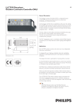
HPX STANDARD Contents ii EMC COMPLIANCE This product is approved for use in Europe and Australia/New Zealand and conforms to the following standards: European Norms Australian / New Zealand Standards EN 55015 AS/NZS CISPR15 IEC 60439-1 AS/NZS 3439.1 IEC 60439.3 AS/NZS 3439.3 IEC 60950 AS/NZS 60950 To ensure continued compliance with EMC Directive 89/336 and the Australian Radiocommunications Act 1992, use only high quality data cables with continuous shield, and connectors with conductive backshells. Examples of such cables are: DMX: Belden 8102 100% Aluminium foil screen, 65% Copper braid. This device complies with part 15 of the FCC Rules. Operation is subject to the following two conditions: (1) This device may not cause harmful interference, and (2) this device must accept any interference received, including interference that may cause undesired operation. Changes or modifications not expressly approved by the manufacturer could void the user's authority to operate the equipment. DISCLAIMER Information contained in this manual is subject to change without notice and does not represent a commitment on the part of the vendor. JANDS PTY LTD shall not be liable for any loss or damage whatsoever arising from the use of information or any error contained in this manual. It is recommended that all service and repairs on this product be carried out by JANDS PTY LTD or its authorised service agents. JANDS PTY LTD cannot accept any liability whatsoever for any loss or damage caused by service, maintenance or repair by unauthorised personnel, or by use other than that intended by the manufacturer. JANDS HPX Series products must only be used for the purpose they were intended by the manufacturer and in conjunction with this operating manual. Disconnect mains power when not in use. Designed in Australia / Manufactured in China JANDS PTY LTD ACN 001 187 837 40 Kent Rd Locked Bag 15 Mascot NSW 2020 MASCOT NSW 1460 Sydney Australia Sydney Australia Phone: +61-2-9582-0909 Email: [email protected] Fax: +61-2-9582-0999 Web: JANDS PTY LTD 2006 All rights reserved www.jands.com.au Revision 5 Revision 04 –03 May 2007 HPX DIMMER 19 July 2007 USER MANUAL Contents iii Table of Contents Table of Contents............................................................................. iii 1.0 About This Manual.................................................................... 1 1.1 Important Safety Information ........................................................................ 1 2.0 Introduction............................................................................... 2 2.1 Features ....................................................................................................... 2 3.0 Equipment Description ............................................................ 3 3.1 Front panel layout......................................................................................... 3 4.0 Getting Started.......................................................................... 4 4.1 Connecting power......................................................................................... 4 4.2 Powering up ................................................................................................. 4 4.3 Connecting loads.......................................................................................... 4 4.3.1 Changing the channel configuration ................................................ 4 4.4 Connecting DMX-512 input .......................................................................... 5 4.4.1 Changing the DMX Address ............................................................ 5 4.4.2 DMX Termination ............................................................................ 5 5.0 Operation................................................................................... 6 5.1 Menu and setting adjustment ....................................................................... 6 5.1.1 Root Menu....................................................................................... 6 5.1.1.1 Changing the DMX Address ........................................................ 6 5.1.1.2 Displaying the software Version................................................... 6 5.1.1.3 Cap function................................................................................. 8 5.1.2 DMX Termination ............................................................................ 8 5.1.3 DMX Data Loss ............................................................................... 9 5.1.4 Deep Clear ...................................................................................... 9 6.0 Fault Diagnosis ......................................................................... 10 Revision 05 – 19 July 2007 HPX DIMMER USER MANUAL Contents iv 6.1 Output protection ........................................................................................ 10 6.2 Thermal protection...................................................................................... 10 6.3 Neutral-Earth Detection .............................................................................. 10 6.4 Fault finding guide ...................................................................................... 11 7.0 Installation................................................................................. 12 7.1 Ventilation................................................................................................... 12 7.2 Supply Wiring ............................................................................................. 12 8.0 Maintenance .............................................................................. 13 8.1 External Cleaning ....................................................................................... 13 8.2 Internal Cleaning ........................................................................................ 13 8.3 Routine Maintenance.................................................................................. 13 9.0 Technical Data and Specifications......................................... 14 9.1 DMX connector pin-outs ............................................................................. 15 9.2 Socapex connector pin-outs ....................................................................... 15 Revision 05 – 19 July 2007 HPX DIMMER USER MANUAL About This Manual 1 1.0 About This Manual This manual provides general information about the HPX product. The HPX has been designed in a modular format that allows each unit to be factory-built to suit the users’ particular requirements, and as such the product diagrams within this manual may differ from the actual unit provided. 1.1 Important Safety Information o This product is NOT rated for outdoor use. Ensure the HPX is protected from moisture and is not used in wet areas. o Output sockets may have dangerous voltages present even when the channels are driven off. Switch off the channel circuit breaker before connecting and disconnecting loads or replacing load lamps. o The HPX should be properly mounted on a flat stable surface. o Provide adequate ventilation during use. Do not obstruct airflow around the vents. o Do not run the power cables under carpet or other insulating substances. Arrange the cables away from traffic areas and where they may become a tripping hazard. o Inspect the unit for damage prior to each use. If the unit is dropped or damaged in any way, it must be inspected by a qualified person before use. o High voltages are present inside the unit. Do not operate with the lid removed. o Disconnect from mains supply when not in use. o No user serviceable parts inside. Revision 05 – 19 July 2007 HPX DIMMER USER MANUAL Introduction 2 2.0 Introduction The HPX is a professional dimmer product designed primarily for use with incandescent loads. It uses microprocessor-based digital control for accurate dimming and provides easy to use in-built test functions and facilities. Digital control is via the ANSI E1.11 USITT DMX-512-A specification protocol. Control signal to the dimmer is via a standard 5-pin socket on the front panel, while the dimmed outlets and power entry are located on the rear panel. When ordered with the Channel control option, any channel may be configured to operate as a mains switch or dimmer. 2.1 Features o High brightness display o Simplified menu operation o Digital DMX-512 start channel display o Inbuilt DMX-512 terminator o Two DMX snapshots (scenes) o Built-in test facilities and check functions o Multiple speed chase function o Soft turn on characteristic o Multiple dedicated status indicators o Three phase power indicator LEDs o Dimming curve set for linear relationship between control input and output power o Multiple phase power operation modes o Low acoustic/electrical noise o Dual temperature-controlled DC fans o Toroidal output chokes o Temperature monitor and soft thermal cut-out o Rack mounted (3 or 4 rack units) o Rugged construction o Operates from mains supplies 100V to 230VAC, 40 to 66Hz Revision 05 – 19 July 2007 HPX DIMMER USER MANUAL Equipment Description 3 3.0 Equipment Description 3.1 Front panel layout Refer to Figure 1 for a description of the front panel controls. 13 1 (REAR) 6, 7, 8, 9 5 3 4 14 10 2 11, 12 Figure.1 HPX front panel layout 1. Channel output sockets (rear panel): The output sockets are located on the back panel. 2. Channel circuit breakers: If a breaker trips during use ensure the fault has been cleared before resetting. 3. + and - buttons: These buttons select the DMX-512 start channel, are used to move through menus and select functions and change values. 4. EXIT and MENU/ buttons: These buttons are used to navigate through the menus and set DMX address. 5. 3-Digit Display: Indicates currently selected DMX-512 start channel, the menu position, and the various function options. 6. SIGNAL LED: Indicates the presence of DMX-512 signals. 7. ERROR LED: Flashes in the presence of a fault. In normal operation this LED should be off. 8. IC LED: The Internal Control LED Illuminates when control is internal, ie. not from the DMX-512 input. 9. TERM LED: Illuminates when the Terminate function is active. 10. PHASE LEDs: Three blue LEDs (one for each phase) indicate that the mains supply is available. Note that all three LEDs should illuminate when power is available regardless of the type of the mains supply used to power the HPX. 11. DMX IN SOCKET: Standard 5-pin AXR connector accepts DMX-512 signals from the controller. 12. DMX LOOP SOCKET: Standard 5-pin AXR connector links the DMX-512 signals to other dimmers or devices. 13. Channel Switch: A switch per output channel is used to change the mode of operation of that channel. 14. Channel LED: A multicolour LED per output channel is used to indicate the mode and drive level of that channel. Revision 05 – 19 July 2007 HPX DIMMER USER MANUAL Getting Started 4 4.0 Getting Started The HPX would normally be rack mounted before any wiring is terminated. Refer to Section 6.0 Installation for installation details. 4.1 Connecting power The HPX dimmer may be supplied with a mains inlet cable and multipin connector, mains inlet cable and no connector, or with no inlet cable fitted. Refer to Section 7.2 for details on mains termination connection methods. Always connect to a supply that is protected by fuses or circuit breakers at not more than the specified maximum. . Refer to Section 9.0 Technical Data and Specifications. 4.2 Powering up Turn on the power and check that the three blue phase power indicator LEDs A, B, and C are illuminated before connecting any loads. If any of the phase LEDs are dim or off, power down and remedy the fault before trying again. If all is well, power down and connect loads. 4.3 Connecting loads Switch off the channel circuit breaker before connecting and disconnecting loads or replacing load lamps. Ensure any plugs are pushed firmly into their sockets. The HPX will drive most incandescent loads as well as pinspots, fans, and dimmable fluorescent tubes. The load should be within the specified limits. 4.3.1 Changing the channel configuration Each HPX channel may be independently configured to dim, switch, turn fully on, or be fully off. To change a channel’s configuration: 1. Press the Channel Switch for the channel to be reconfigured. All of the Channel LEDs now flash to indicate the current mode of operation as shown in Table 1. LED colour Function Green Dim Orange Switch Red Channel fully On Off Channel fully Off Table 1: Channel Indicator functions 2. Continue to press the channel Switch until the required function is indicated by the LED/s. 3. Press and hold the channel switch to record the new setting. Revision 05 – 19 July 2007 HPX DIMMER USER MANUAL Getting Started 4.4 5 Connecting DMX-512 input The input signal to the HPX should conform to the ANSI E1.11 USITT DMX512-A specification. Plug the DMX-512 signal to the “DMX IN” socket. The DMX signal may be daisy-chained to the next DMX receiver via the LOOP connector. The SIGNAL LED indicates the presence of control data. The DMX-512 input is protected against extreme over-voltages across any input pins and from any input to chassis. The “terminating” resistor is not protected against over-voltages. 4.4.1 Changing the DMX Address The DMX-512 address is the DMX-512 channel number that will be used to control HPX dimmer channel 1. HPX dimmer channels 2 and up are controlled from the next DMX-512 channel upward. To change the DMX-512 address: 1. At the root menu adjust the displayed value using the + and – buttons until it matches the required start channel. 2. Press MENU/ to confirm. 4.4.2 DMX Termination In any DMX-512 system the signal should be terminated at the last dimmer or receiver in the chain - the HPX can provide this function. Refer to Section 5.1.2. The TERM LED indicates when the Termination function is active. Note that when termination is active no signal is present at the LOOP connector. Revision 05 – 19 July 2007 HPX DIMMER USER MANUAL Dimmer Operation 6 5.0 Operation This section assumes the HPX has been correctly connected to the mains power supply and a source of DMX-512 control signal. 5.1 Menu and setting adjustment o Pressing MENU/ at any time moves up a menu level or confirms a new setting. o Pressing the EXIT button at any time moves back a menu level with no setting change. o When adjusting a setting, the display will flash briefly once per second for three seconds. If the MENU/ button is pressed within that three seconds, the new value is retained and subsequently takes effect. If no button is pressed within that 3 seconds, or if the EXIT button is pressed within 3 seconds, the setting reverts to the previous value. The menu tree is shown in Figure 2. The function of each menu option is described in Table 2. 5.1.1 Root Menu The root menu is displayed when the Exit button has been pressed sufficient times such that the DMX-512 start channel is displayed. A number of functions are available at the Root Menu as detailed in the following sections. 5.1.1.1 Changing the DMX Address The DMX address is the DMX-512 channel number that will be used to control HPX dimmer channel 1. HPX dimmer channels 2 and up are controlled from the next DMX-512 channel upward. To change the DMX address: 1. At the root menu adjust the displayed value until it matches the required start channel. 2. Press MENU/. 5.1.1.2 Displaying the software Version To display the software version press and hold the EXIT button while the Root Menu is displayed. Note that when EXIT is pressed the channel configuration is indicated on the channel LEDs. Revision 05 – 19 July 2007 HPX DIMMER USER MANUAL Dimmer Operation 7 DMX Address + - + ↵ E - Test Channel E + Change DMX - NE Protection ↵ Select Channel E ↵ + +- Sets NE fault detector on or off ↵ Hold Output - ↵ DMX Setups ↵ E + ↵ NE Protection E +- Use Channel Select buttons to activate channels ↵ ↵ E - + Fade to Scene 1 ↵ Termination - Output Cap Signal Loss - + ↵ + +- Sets dimmer to fade to Scene 1 when DMX is lost Toggles DMX Termination function ↵ Set Cap Value Sets dimmer to hold data when DMX is lost Sets cap value - Temperature + - ↵ System Checks DMX Packets/Sec E Mains Phases + - Scene Control Mains Frequency ↵ E + Hold Hold ↵ to record the selected Scene ↵ ↵ Press ↵ to activate the selected Scene E ↵ E Select Speed +- - Drive All Chans + +- - Activate Chase + Select Scene - ↵ E Select Drive Level +- ↵ (Menu) E (Cancel/Exit) Move right Move left Figure 2: Menu Tree Revision 05 – 19 July 2007 HPX DIMMER USER MANUAL Dimmer Operation 8 First Level Second Level Third Level Description Chn - - Use channel select buttons drive channel/s to full n-E SIG On-off no.S HLd When ON the N-E fault detector is enabled SIG no.S Sc.1 Set the HPX to fade to Scene 1 upon loss of DMX data SIG End - Toggle the DMX terminate function. The TERM LED indicates if the terminate function is active. CAP 40-100 - Set the Cap level percentage. 100 = normal operation. Chc 24.C - Display the internal measured temperature in degrees Celcius CHC Chc D.21 3.PH - Display the DMX packet rate (per second) Chc Scn 50.H SC1 - Display the mains frequency Scn SC2 - Press MENU/ to play Scene 2. Press and hold MENU/ to record Scene 2. CHS ALL SP1-SP9 0-FL - Activate the chase and set the rate Set the HPX to hold the current output upon loss of DMX data Display the number of connected phases. Note that 2.PH is displayed when 1 or 2 phase power is connected. Press MENU/ to play Scene 1. Press and hold MENU/ to record Scene 1. Drive all channels in 10% increments Table 2: Menu Function Reference 5.1.1.3 Cap function The Cap function is used to scale the output of all channels by a preset percentage. For example setting to “95” enables 230V lamps to be run from 240V without reducing lamp life (95% of 240V = 230V). 5.1.2 DMX Termination Any long DMX-512 data line must be terminated at the end for correct operation, and the HPX provides this function. Selecting the “End” option toggles the terminate function. The TERM LED on the front panel indicates when the DMX-512 is terminated. Note that no signal is present on the DMX OUT socket when the terminate function is active. Revision 05 – 19 July 2007 HPX DIMMER USER MANUAL Dimmer Operation 5.1.3 9 DMX Data Loss The HPX can be configured to hold the current output or dim to Scene 1 when DMX-512 data is interrupted. To set the dimmer to fade to Scene 1, select “SC.1” in the “no.S” menu. To set the dimmer to hold the current output, select “HLD” in the “No.S menu. Note that in both cases the HPX will turn all DMX controlled outputs off if data is not restored within 10 minutes. 5.1.4 Deep Clear The HPX includes a deep clear facility to enable the internal processor to be reset to the factory default settings. In general this should not be required however if necessary the following procedure should be followed: 1. Turn HPX power off 2 Press and hold the “+” and “-“ buttons 3. Turn the HPX power on 4. Release the buttons held in step 1 5. Press the MENU/ button Revision 05 – 19 July 2007 HPX DIMMER USER MANUAL Fault Diagnosis 10 6.0 Fault Diagnosis NOTE Contact your authorised JANDS Distributor for repairs or servicing. In Australia refer all repairs to an authorised JANDS service agent or return the faulty unit in suitable packaging to: JANDS ELECTRONICS Service Dept, 26 Kent Rd Mascot NSW 2020 Australia 6.1 Output protection Each of the output circuits is protected by a fast-acting thermal/magnetic circuit breaker. These breakers are designed to pass the rated current, but will disconnect the output circuit for any overload condition (the larger the overload, the quicker the disconnection). If a circuit breaker trips there’s either a fault which should be rectified or the channel is overloaded. 6.2 Thermal protection The HPX dimmers feature temperature-controlled fan cooling. As the internal temperature of the dimmer increases, the fan speed also increases. The inlet and exhaust areas of the chassis must be kept clear while the HPX is on. The HPX continuously monitors the internal heatsink temperature. As the temperature approaches the rated maximum the internal processor attempts to reduce the heat build up by reducing the output levels. If the temperature continues to rise the dimmer will shut down the output drive, however this should only be necessary if there is inadequate ventilation or if the ambient temperature is above the rated maximum. Refer to Section 7.1 Ventilation regarding HPX ventilation requirements. 6.3 Neutral-Earth Detection The HPX includes a fault detector that monitors the Neutral-Earth (N-E) voltage – in normal operation there should be little of no voltage difference between the Neutral and Earth. If the voltage exceeds a predetermined amount the outputs are turned off. The N-E fault detector may be disabled in the menu. Revision 05 – 19 July 2007 HPX DIMMER USER MANUAL Fault Diagnosis 11 6.4 Fault finding guide FAULT SYMPTOM Breaker trips One channel flickers when dimmed POSSIBLE CAUSE REMEDY Excessive load Reduce channel loading Lamp or wiring fault Check lamps and wiring Poor ventilation Increase air flow to HPX side vents Faulty HPX Service HPX DMX source problem Softpatch another console fader Service console Faulty HPX channel Service HPX Same load flickers on another Channel Insufficient or very inductive load Connect >100W incandescent lamp in parallel NE Error on display Poor Earth or Neutral connection Check supply wiring. Disable N-E detector in menu. All Channels flicker when dimmed Incorrect DMX protocol / wiring Replace DMX source / wiring Un-terminated DMX line Activate Terminate facility on the last HPX Mains control tones exceed limits Contact factory Faulty DMX wiring/connections Repair Faulty console Repair Faulty HPX Service HPX Error LED flashing Over-temperature Improve HPX ventilation Error LED on continuously Recent over-temperature Improve HPX ventilation DMX control errors Check DMX wiring, console HPX memory corrupt Deep Clear HPX Software failure Service HPX No signal at DMX Loop output Terminate facility active De-activate Terminate facility Channels wont drive to full CAP function enabled Change CAP Setting in menu HPX very hot Increase air flow to HPX vents HPX very hot Increase air flow to HPX vents Signal LED flickers HPX shuts down Revision 05 – 19 July 2007 HPX DIMMER USER MANUAL Installation 12 7.0 Installation The HPX is designed for use in 19 inch racks or a 19 inch bar frame, and occupies 3 or 4 rack units. The HPX is supplied with rear rack mounting support brackets, which provide additional support for touring applications. The mains supply power cable entry is located at the rear right side of the rack when viewed from the front. Ensure adequate access to the power plug when mounting HPX’s in racks. 7.1 Ventilation The HPX dimmer is fan-cooled, with the air intake at the right and air exhaust at the left when viewed from the front. Equipment racks must have adequate ventilation for the side-to-side airflow. Fully enclosed racks will cause overheating problems. Racks must allow at least 100 square centimetres of air venting per HPX at each side of the rack, level with the intake and exhaust slots. Additional venting area will serve to further reduce internal temperatures and will enhance the HPX’s operational reliability. HPX’s may be stacked in racks without intervening rack spaces as long as the racks are adequately vented at the sides. Racks of HPX’s must be placed such that one rack does not breathe the hot exhaust of the rack next to it. Allow at least 300mm (12") between racks unless duty cycles are light. 7.2 Supply Wiring The HPX has been designed to run from commonly found star power systems, ie. where a neutral is available. The incoming mains supply must be protected at not more than the specified maximum. When no cable is supplied, the HPX must have its labelled terminals connected to the supply phases as indicated in Table 3. HPX Power Terminal Supply Type A B1 B2 C N E Notes Two wire A A A A N E Link terminals A, B1, B2, and C A A B B N E Remove link between B1 and B2 A B B C N E Insert link between B1 and B2 (A + N) Three Wire (2A + N) Four Wire (3A+N) Table 3: HPX Power Supply Connections Revision 05 – 19 July 2007 HPX DIMMER USER MANUAL Maintenance 13 8.0 Maintenance With care, the HPX will require little or no maintenance. However periodic electrical safety checks may be required by law in some countries. 8.1 External Cleaning If the front panel requires cleaning, wipe with a mild detergent on a damp soft cloth. NO NOT allow liquids into the chassis. DO NOT spray liquids onto the front panel. DO NOT use solvents for cleaning the front panel. 8.2 Internal Cleaning The HPX will require little internal maintenance other than periodic flushing to prevent the fan and air-path becoming clogged with dirt or fluff. 8.3 • ISOLATE POWER to the dimmer (by disconnecting the power cable or locking off the mains supply isolator). • Remove the lid. • Blow clean the fan and internals with compressed air from left to right. • DO NOT "spin" the fan with compressed air - the blades may break off. • When the fan and internals are clean, replace the lid and screws, and re-connect the power cable. Routine Maintenance Installed HPX’s should be routinely flushed of dust at six- to twelve-month periods. Touring HPX’s may need a more rigorous maintenance routine, which should include: • Inspection of chassis for evidence of impact damage and physical abuse • Inspection of outlets for wear and damage • Inspection of power cable for wear and damage • Electrical checking of ground integrity from power cable to chassis • Electrical checking of ground integrity from power cable to outlet grounds • Flushing of dust build-up • Testing the operation of all front panel switches and breakers A Neutral-Earth test may show a low reading. This is normal and is a consequence of the N-E voltage detector detailed in Section 6.4. Revision 05 – 19 July 2007 HPX DIMMER USER MANUAL Technical Data and Specifications 9.0 14 Technical Data and Specifications PARAMETER Active-Neutral Supply Voltage HPX 100-230VAC ±10% Full size neutral required Supply Frequency 40-66Hz Supply Protection 10K Amps Rated Insulation Voltage Rated Output Current 430VAC Phase to Phase, 250VAC Phase to Neutral 10 Amps or 20 Amps per channel Minimum Power/Channel Maximum Dissipation 25W <24 W/channel Electric Shock protection SELV System Earth Type MEN Output Protection Thermal/magnetic circuit breakers Maximum Ambient Temp 40ºC Maximum Altitude Over-temperature cutout Control Signal DMX Input 2000m Soft limit starts at 92°C, Full cutout at 100°C ANSI E1.11 USITT DMX-512-A specification 5 pin AXR male / female Snapshot Scenes Test Function Level 2 Individual Channels @ 100% All Channels @ 10% steps LED Indicators SIGNAL, ERROR, TERM, IC Phases A, B, and C Ingress protection IP20 Internal Separation Form 1 Environment Size (mm) Weight Rack mounting requirements B 478 (w) x 133 (or 178) (h) x 451 (d) 22 kg net 3 (or 4) x 19” rack spaces / standard spacing for mounting holes Ventilation required at sides of rack Power inlet at rear right (looking from front of unit) Rear access required for patching outputs Revision 05 – 19 July 2007 HPX DIMMER USER MANUAL Technical Data and Specifications 9.1 9.2 15 DMX connector pin-outs PIN No CONNECTION (DMX IN) CONNECTION (LOOP) 1 SHIELD SHIELD 2 IN- OUT- 3 IN+ OUT+ 4 DMX Loop pin 4 DMX In pin 4 5 DMX Loop pin 5 DMX In pin 5 Socapex connector pin-outs Revision 05 – 19 July 2007 PIN No Socapex 1 Socapex 2 1 A1 A7 2 N1 N7 3 A2 A8 4 N2 N8 5 A3 A9 6 N3 N9 7 A4 A10 8 N4 N10 9 A5 A11 10 N5 N11 11 A6 A12 12 N6 N12 13 E1 E7 14 E2 E8 15 E3 E8 16 E4 E10 17 E5 E11 18 E6 E12 19 NC NC HPX DIMMER USER MANUAL