1
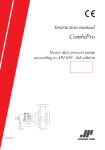
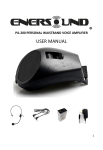
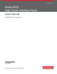
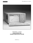
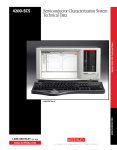
Model 4210-MMPC-C
Keithley Instruments, Inc.
28775 Aurora Road
Cleveland, Ohio 44139
1-888-KEITHLEY
www.keithley.com
Multi-Measurement Prober Cable Kit
Quick Start Guide
Overview
The Keithley Instruments Model 4210-MMPC-C multi-measurement cable kit (see Figure 1) is a collection of
standard and custom connectors and accessories used to take I-V and C-V measurements using a single prober
cable setup. It is also used with the Keithley Model 4200-PIV-A package to perform pulse I-V measurements. This
kit has been assembled for use with the Cascade Microtech 12000 prober series (manipulator type DCM-200
series).
NOTE
For C-V testing, this Quick Start Guide applies to both the Model 4200-CVU card and
the new 1 kHz Model 4210-CVU card. For pulse I-V testing, this guide also applies to
the Model 4200-PG2 card and the new Model 4205-PG2 card.
Prober cable kit contents
Figure 1 shows the cables, adapters, and supplies that are included in the Model 4210-MMPC-C
multi-measurement cable kit.
Figure 1: Model 4210-MMPC-C multi-measurement prober cable kit
PA-1001 Rev. B / February 2010
1
Model 4210-MMPC-C
Multi-Measurement Prober Cable Kit
Quick Start Guide
Keithley Instruments, Inc.
28775 Aurora Road
Cleveland, Ohio 44139
1-888-KEITHLEY
www.keithley.com
Quick Start Guide topics
The guide contains information about the installation and use of this cable kit:
Connecting Model 4200 instrumentation to the prober bulkhead: Explains how to make connections from
the Model 4200 to the prober bulkhead.
Installing the prober cable kits: Explains how to make connections from the prober bulkhead to the prober
pins.
Usage scenarios: Provides the specific prober cable setups for I-V testing (2-wire and 4-wire) and C-V
testing (2-wire and 4-wire). It also provides the setup for performing pulse I-V measurements using the
Keithley Model 4200-PIV-A.
Related documents
The following documents (in PDF format) are located on the Model 4200 Complete Reference CD:
PA-993: This is a one-page packing list for the Model 4210-MMPC-S Multi-Measurement Prober Cable Kit
for the Suss MicroTec PA200/300 series prober. A photo shows all the components of the cable kit.
PA-994: This is a one-page packing list for the Model 4210-MMPC-C Multi-Measurement Prober Cable Kit
for the Cascade MicroTech 12000 series prober. A photo shows all the components of the cable kit.
White Paper – Labs’ Demands for Greater Measurement Flexibility Require Cabling Systems Capable of
Accommodating Multiple Measurement Types: This white paper explains the different cabling requirements
for I-V, C-V, and pulse I-V testing. It also describes an easy-to-use single multi-measurement cabling
system (Model 4210-MMPC-C for the Cascade Microtech 12000 prober).
Connecting Model 4200 instrumentation to the prober bulkhead
WARNING
To prevent injury or death due to electric shock, remove all power from the
Model 4200-SCS and shut down the Cascade prober before installing the
prober cable kit.
The Model 4200 connects to the female triax connectors on the prober bulkhead.
I-V testing
For I-V testing, connect the triax cables of your Model 4200 source-measure units (SMUs) to the standard female
triax connectors on the bulkhead of the prober. Figure 2 shows two Model 4200 SMU prober connections.
NOTE
2
Figure 2 shows SMUs that do not use preamps. These SMUs use the supplied triax
cables that are terminated with a miniature triax connector on one end and a standard
triax connector on the other end. If your SMUs are equipped with preamps, use the
supplied cables that are terminated with standard triax connectors on both ends.
Figure 2 shows both cables.
PA-1001 Rev. B / February 2010
Model 4210-MMPC-C
Keithley Instruments, Inc.
28775 Aurora Road
Cleveland, Ohio 44139
1-888-KEITHLEY
www.keithley.com
Multi-Measurement Prober Cable Kit
Quick Start Guide
Figure 2: Model 4200 SMU connections to the prober
C-V testing
Two prober cable kits include the cable adapters needed to connect the subminiature version A (SMA) cables of
the Model 4210-CVU to the female triax connectors on the bulkhead of the prober. Figure 3 shows how to make the
connections. A torque wrench is supplied with the Model 4210-CVU.
Figure 3: Model 4210-CVU prober connections
PA-1001 Rev. B / February 2010
3
Model 4210-MMPC-C
Keithley Instruments, Inc.
28775 Aurora Road
Cleveland, Ohio 44139
1-888-KEITHLEY
www.keithley.com
Multi-Measurement Prober Cable Kit
Quick Start Guide
Pulse I-V testing using the Keithley Model 4200-PIV-A
NOTE
Four prober cable kits are required for 4-pin, PIV-A pulse I-V testing.
Perform 4-pin pulse I-V measurements using four prober cable kits with the Keithley Instruments Model 4200-PIV-A
package, which includes a scope card, pulse generator card, software, and other components.
Use the supplied cables and connectors to connect the Model 4200 to the bulkhead of the prober (see Figures 4
and 5).
Figure 4 shows the Model 4200 connections to the prober and the trigger connection between the scope card
(Model 4200-SCP2) and pulse generator card (Model 4205-PG2). Figure 5 identifies the cables and adapters used
to make the connections.
NOTE
Figure 4 shows source-measure units (SMUs) that are not equipped with preamps.
These SMUs use the supplied triax cables that are terminated with a miniature triax
connector on one end and a standard triax connector on the other end. If your SMUs
are equipped with preamps, use the supplied cables that are terminated with standard
triax connectors on both ends. Figure 5D shows both cables.
Figure 4: Model 4200-PIV-A instrumentation connections
4
PA-1001 Rev. B / February 2010
Model 4210-MMPC-C
Keithley Instruments, Inc.
28775 Aurora Road
Cleveland, Ohio 44139
1-888-KEITHLEY
www.keithley.com
Multi-Measurement Prober Cable Kit
Quick Start Guide
Figure 5: Cables and adapters used for instrumentation connections
Installing the prober cable kits: Basic cable setup
Figure 6 shows the basic cable setup for the 2-pin I-V and C-V testing scenarios described in this guide. The 4-pin
I-V and 4-pin C-V testing scenarios require minor setup changes; pulse I-V setup, which is more complex, is
described later in this Quick Start Guide.
Figure 6: Basic 2-pin prober cable setup
PA-1001 Rev. B / February 2010
5
Model 4210-MMPC-C
Keithley Instruments, Inc.
28775 Aurora Road
Cleveland, Ohio 44139
1-888-KEITHLEY
www.keithley.com
Multi-Measurement Prober Cable Kit
Quick Start Guide
Installation guidelines
Figure 7 shows the prober cable assemblies of four Model 4200-MMPC-C kits installed in a Cascade Microtech
12000 series prober.
Figure 7: Four prober cable assemblies installed in a Cascade prober
To install the Cascade prober kit:
1. Referring to Figure 7, mount each grounding bracket onto the tube of a manipulator.
2. Firmly tighten the set screws to secure the brackets to the tubes.
3. Black jumpers are used to connect the commons of the cable assemblies together. The jumpers plug into
the grounding brackets. Referring to Figure 7, connect the jumpers from one grounding bracket to another.
For the basic 2-pin setup in Figure 6, it is good practice to install the second jumper. It not only improves the
connection, but it is a good place to store the extra jumper.
NOTE
Figure 7 shows an example of good routing for the jumper wires. When routing the
wires, consider the possible movements of the manipulators.
4. Referring to Figure 6, connect the prober manipulators to the prober bulkhead connectors using the supplied
triax cables. Each cable is terminated with a full-triax connector on one end and a mini-triax connector on
the other end. Figure 7 shows the mini-triax connectors mounted on the manipulators.
6
PA-1001 Rev. B / February 2010
Model 4210-MMPC-C
Keithley Instruments, Inc.
28775 Aurora Road
Cleveland, Ohio 44139
1-888-KEITHLEY
www.keithley.com
Multi-Measurement Prober Cable Kit
Quick Start Guide
Usage scenarios
I-V testing: 2-pin I-V setup
NOTE
The setup for 2-pin I-V testing requires two prober cable kits.
With two Model 4200-SMUs connected to the prober bulkhead, use the fundamental setup shown in Figure 8 to
perform 2-pin I-V testing. Figure 2 shows the SMU connections to the outside of the bulkhead.
Figure 8: Test setup for 2-pin I-V testing
I-V testing: 4-pin I-V setup
NOTE
The setup for 4-pin I-V testing requires four prober cable kits.
With four Model 4200-SMUs connected to the prober bulkhead, use the setup shown in Figure 9 to perform 4-pin
I-V testing. Figure 2 shows two SMUs connected to one of the bulkhead connection panels. Connect two additional
PA-1001 Rev. B / February 2010
7
Model 4210-MMPC-C
Keithley Instruments, Inc.
28775 Aurora Road
Cleveland, Ohio 44139
1-888-KEITHLEY
www.keithley.com
Multi-Measurement Prober Cable Kit
Quick Start Guide
Figure 9: Test setup for 4-pin I-V testing
C-V testing: 2-pin C-V setup
NOTE
The setup for 2-pin C-V testing requires two prober cable kits.
With a Model 4210-CVU connected to the prober bulkhead, use the fundamental setup shown in Figure 10 to
perform 2-pin C-V testing. Figure 4 shows the CVU connections to the outside of the bulkhead.
Figure 10: Test setup for 2-pin C-V testing
8
PA-1001 Rev. B / February 2010
Model 4210-MMPC-C
Keithley Instruments, Inc.
28775 Aurora Road
Cleveland, Ohio 44139
1-888-KEITHLEY
www.keithley.com
Multi-Measurement Prober Cable Kit
Quick Start Guide
C-V testing: 4-pin C-V setup
NOTE
The setup for 4-pin C-V testing requires four prober cable kits.
A typical test for a field effect transistor (FET) is to connect the drain, bulk, and source together and perform the
measurement across the gate. With a Model 4200-CVU connected to the prober bulkhead, use the setup shown in
Figure 11 to perform 4-pin C-V testing.
Figure 11: Test setup for 4-pin C-V testing
Four-pin pulse I-V test setup using the Keithley Model 4200-PIV-A
NOTE
The setup for 4-pin pulse I-V testing requires four prober cable kits.
The Model 4200-PIV-A is a factory-installed package that includes a scope card, pulse generator card, software
and other components to perform 4-pin pulse I-V measurements.
The test setup for using the Model 4200-PIV-A is shown in Figures 12, 13, and 14. Figure 12 shows the
connections from the prober bulkhead to the gate and source of the 4-terminal device. Figure 13 shows the
connections from the bulkhead to the drain and bulk. Figure 14 shows the jumper connections. The four jumpers
connect the commons of the cable assemblies together. These four jumper connections are required to complete
the test circuit signal path.
Figure 4 shows how the Model 4200 connects to the outside of the bulkhead.
PA-1001 Rev. B / February 2010
9
Model 4210-MMPC-C
Keithley Instruments, Inc.
28775 Aurora Road
Cleveland, Ohio 44139
1-888-KEITHLEY
www.keithley.com
NOTE
Multi-Measurement Prober Cable Kit
Quick Start Guide
Details on using the Model 4200-PIV-A package are provided in the Model 4200-SCS
User’s Manual (see How to use the Model 4200-SCS to perform a pulse I-V test on
my device in Section 3). Figure 3-25 shows the block diagram of the test setup.
Figure 12: Connections to the gate and source of the DUT
Figure 13: Connections to the drain and bulk
Figure 14: Jumper connections
10
PA-1001 Rev. B / February 2010