1
Semiconductor Characterization
System
4200-SCS
The powerful test library management tools included allow standardizing test
methods and extractions to ensure consistent test results. The 4200-SCS offers
tremendous flexibility, with hardware options that include four different
switch matrix configurations, a choice of Keithley and Agilent C-V meters, and
pulse generators. A variety of customer support packages are also available,
including applications support, calibration, and repair.
A Total System Solution
The Model 4200-SCS provides a total system solution for DC characterization
of semiconductor devices and test structures. This advanced parameter analyzer provides intuitive and sophisticated capabilities for semiconductor device
characterization. The 4200-SCS combines unprecedented measurement speed
and accuracy with an embedded Windows NT-based PC and the Keithley
Interactive Test Environment (KITE) to provide a powerful single-box solution.
The Keithley Interactive Test Environment allows users to gain familiarity
quickly with tasks such as managing tests and results and generating reports.
Sophisticated and simple test sequencing and external instrument drivers simplify performing automated device and wafer testing with combined I-V and
C-V measurements. The 4200-SCS is modular and configurable. The system
supports up to eight Source-Measure Units, including up to four high-power
SMUs with 1A/20W capability.
1.888.KEITHLEY
Extended Measurement Resolution
An optional Remote PreAmp, the 4200-PA, extends the system’s measurement resolution from 100fA to
0.1fA by effectively adding five current ranges to either SMU model. The PreAmp module is fully integrated with the system; to the user, the SMU simply appears to have additional measurement resolution available. The Remote PreAmp is shipped installed on the back panel of the 4200-SCS for local operation. This
installation allows for standard cabling to a prober, test fixture, or switch matrix. Users can remove the
PreAmp from the back panel and place it in a remote location (such as in a light-tight enclosure or on the
prober platen) to eliminate measurement problems due to long cables. Platen mounts and triax panel
mount accessories are available.
KTE Interactive Software Tools
KTE Interactive includes four software tools for operating and maintaining the 4200-SCS in addition to
the Windows® NT operating system:
• Keithley Interactive Test Environment (KITE)—The 4200-SCS device characterization application
• Keithley User Library Tool (KULT)—Allows test engineers to integrate custom algorithms into KITE
using 4200-SCS or external instruments.
• Keithley Configuration Utility (KCON)—Allows test engineers to define the configuration of GPIB
instruments, switch matrices, and analytical probers connected to the 4200-SCS. It also provides system diagnostics functions.
• Keithley External Control Interface (KXCI)—The 4200-SCS application for controlling the 4200-SCS
from an external computer via the GPIB bus.
The Keithley Interactive Test Environment (KITE)
The Keithley Interactive Test Environment (KITE) is the Model 4200-SCS Windows device characterization
application. It provides advanced test definition, parameter analysis and graphing, and automation capabilities required for modern semiconductor characterization.
(U.S. only)
www.keithley.com
A
G R E A T E R
M E A S U R E
O F
C O N F I D E N C E
SEMICONDUCTOR
• Intuitive, point-and-click Windowsbased environment
• Unique Remote PreAmps extend the
resolution of SMUs to 0.1fA
• Self-contained PC provides fast test
setup, powerful data analysis,
graphing and printing, and on-board
mass storage of test results.
• Unique browser-style Project
Navigator organizes tests by device
type, allows access to multiple
tests, and provides test sequencing
and looping control
• Integrated support for Keithley
Model 590 and Agilent 4284 C-V
meters, Keithley switch matrix
configurations, and Agilent 81110
pulse generators
• Hardware controlled by the Keithley
Interactive Test Environment (KITE).
User Test Module function extends
KITE for external instrument control
and test station integration.
• Includes software drivers for
Cascade Microtech Summit 12K
Series, Karl Suss Model PA-200,
Micromanipulator Model 8860, and
manual probers.
Lab grade DC device charactterization
The easy-to-use Model 4200-SCS Semiconductor Characterization System performs lab grade DC device characterization, real-time plotting, and analysis with
high precision and sub-femtoamp resolution. The 4200-SCS offers the most
advanced capabilities available in a fully integrated characterization system,
including a complete, embedded PC with Windows NT operating system and
mass storage. Its self-documenting, point-and-click interface speeds and simplifies the process of taking data, so users can begin analyzing their results sooner.
Semiconductor Characterization
System
4200-SCS
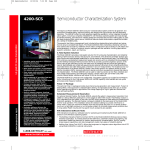
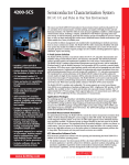
The Keithley Interactive
Test Environment is
designed to let users
understand device
behavior quickly. When
running a test sequence,
users can view results
and plots for completed
tests while the sequence
is still running. As shown
here, multiple plots can
be viewed at the same
time to get a complete
picture of device performance.
Lab grade DC device charactterization
Ordering Information
4200-SCS/F
Flat Panel Display
4200-SCS/C
Composite Front Bezel;
requires an external SVGA
display
Accessories Supplied
Reference and User Manual on
CD-ROM and printed User
Manual included with 4200-SCS
236-ILC-3 Interlock Cable, 3m
(one included with 4200-SCS)
Note: All 4200-SCS systems and
instrument options are supplied
with required cables of 2m
length.
ACCESSORIES AVAILABLE
COMPUTER OPTIONS
ADDITIONAL CABLES AND CONNECTORS
4200-CRT
4200-MOUSE
4200-RPC-0.3
17˝ SVGA CRT
Microsoft 2 Button Mouse
4200-RPC-2
REMOTE PREAMP MOUNTING OPTIONS
4200-MAG-BASE
4200-VAC-BASE
4200-TMB
Magnetic Base for mounting 4200-PA on a
prober platen
Vacuum Base for mounting 4200-PA on a
prober platen
Triaxial mounting bracket for mounting 4200PA on a triaxial mounting panel
4200-RPC-3
4200-RPC-6
4200-TRX-0.3
OTHER ACCESSORIES
4200-MAN
4200-CART
8006
8007
Printed Manual Set
Roll-Around Cart
Component Test Fixture
Semiconductor Test Fixture
4200-TRX-1
4200-TRX-2
C-V OPTIONS
4200-590
5909
High Frequency C-V Analyzer, 100kHz/1MHz
Calibration Sources for Model 590 C-V
Analyzer
4200-TRX-3
4200-MTRX-1
SWITCH MATRIX OPTIONS
SEMICONDUCTOR
Ultra Low Current 100fA offset, 30µV offset, remote or local sense
Low Current
1pA offset, 40µV offset, 12-360 pins, local
sense only
General Purpose 100pA offset, 5µV offset, 12-360 pins, remote
sense
4200-MTRX-2
4200-MTRX-3
CABINETS AND MOUNTING ACCESSORIES
4200-CAB-20UX
4200-CAB-25UX
4200-CAB-34UX
4200-RM
4200-CRT-RM
4200-KEY-RM
2288-1G
1.888.KEITHLEY
20U Cabinet (35 in.)
25U Cabinet (44 in.)
34U Cabinet (60 in.)
Slide Rack Mounting Kit for 4200-SCS/F and
4200-SCS/C
Fixed Rack Mounting Kit for 4200-CRT
Slide Rack Mounting Kit for standard keyboard
and pointing device
Model 590 Rack Mount Kit
236-ILC-3
7007-1
7007-2
7078-TRX-BNC
Remote PreAmp Cable, 0.3m (for use inside
prober shield)
Remote PreAmp Cable, 2m (for remote location
of 4200-PA, one included with each 4200-PA)
Remote PreAmp Cable, 3m (for remote location
of 4200-PA)
Remote PreAmp Cable, 6m (for remote location
of 4200-PA)
Ultra Low Noise PreAmp Triax Cable, 0.3m,
(Triax-Triax, connects 4200-PA to a test fixture,
recommended for remote location of the
4200-PA)
Ultra Low Noise PreAmp Triax Cable, 1m,
(Triax-Triax, connects 4200-PA to a test fixture)
Ultra Low Noise PreAmp Triax Cable, 2m,
(Triax-Triax, connects 4200-PA to a test fixture,
two included with each 4200-PA)
Ultra Low Noise PreAmp Triax Cable, 3m,
(Triax-Triax, connects 4200-PA to a test fixture)
Ultra Low Noise SMU Triax Cable, 1m (Mini
Triax-Triax, connects 4200 SMUs to a test fixture)
Ultra Low Noise SMU Triax Cable, 2m (Mini
Triax-Triax, connects 4200 SMUs to a test fixture, two included with each 4200 SMU that is
not configured with a Remote PreAmp)
Ultra Low Noise SMU Triax Cable, 3m (Mini
Triax-Triax, connects 4200 SMUs to a test fixture)
Interlock Cable, 3m (one included with each
4200-SCS)
Shielded IEEE-488 Cable (1m)
Shielded IEEE-488 Cable (2m)
Coaxial connector for connecting coax instruments to a triax matrix
(U.S. only)
www.keithley.com
A
G R E A T E R
M E A S U R E
O F
C O N F I D E N C E
Semiconductor Characterization
System
Test Sequencing
The Keithley Interactive Test Environment (KITE) provides “point and click”
test sequencing on a device, a group of devices (subsite, module, or test element group), or a user-programmable number of probe sites on a wafer.
KITE Projects
A project is a collection of related tests, organized in a hierarchy that parallels
the physical layout of the devices on a wafer. KITE operates on projects using
an interface called the project navigator. The project navigator simplifies
organizing test files, test execution, and test sequencing. The project navigator
organizes tests into a logical hierarchy presented in a browser style format.
This structure allows users to define projects around wafer testing:
Keithley User Library Tool (KULT)
The Keithley User Library Tool supports creating and integrating C-language
subroutine libraries with the test environment. User library modules are
accessed in KITE through User Test Modules. Factory supplied libraries provide up and running capability for supported instruments. Users can edit and
compile subroutines, then integrate libraries of subroutines with KITE, allowing the 4200-SCS to control an entire test rack from a single user interface.
KULT is derived from the Keithley S600 and S400 Series Parametric Test
Systems. This simplifies migration of test libraries between the 4200-SCS and
Keithley parametric test systems.
• The project level organizes subsites and controls wafer looping execution.
• The subsite level organizes devices and controls subsite test sequencing.
• The device level organizes test modules, manages test module libraries and
controls device test sequencing.
• The test module level performs tests, analyzes data, and plots results.
Prober Control
Keithley provides integrated prober control for supported analytical probers
when test sequencing is executed on a user-programmable number of probe
sites on a wafer. Contact the factory for a list of supported analytical probers.
A manual prober mode prompts the operator to perform prober operations
during the test sequence.
CURRENT
SPECIFICATIONS
Current
Range1
SPECIFICATION CONDITIONS
Specifications are the performance standards against which the 4200-SMU, 4210-SMU, and 4200-PA
are tested. The measurement and source accuracy are specified at the termination of the supplied
cables.
• 23°C ±5°C, within 1 year of calibration, RH between 5% and 60%, after 30 minutes of warm-up.
• Speed set to NORMAL.
• Guarded Kelvin connection.
• ±1°C and 24 hours from ACAL.
Max.
Voltage
Measure
4210-SMU2
High
Power
SMU
1
100
100
10
1
100
10
1
100
10
1
100
10
1
4200-SMU2
Medium Power
SMU
4200-SMU and 4210-SMU with optional
4200-PA PreAmp
A
mA
mA
mA
mA
µA
µA
µA
nA
nA
nA
pA
pA
pA
21 V
210 V
21 V
210 V
210 V
210 V
210 V
210 V
210 V
210 V
210 V
210 V
210 V
210 V
1
100
100
10
1
100
10
1
100
10
3
1
0.3
100
Source
Accuracy
±(% rdg + amps)
Resolution3
µA
nA
nA
nA
nA
pA
pA
pA
fA
fA
fA
fA
fA
aA
Lab grade DC device charactterization
4200-SCS
0.100 %
0.045 %
0.045 %
0.037 %
0.035 %
0.033 %
0.050%
0.050%
0.050%
0.050 %
0.050 %
0.100 %
0.500%
1.000%
+
+
+
+
+
+
+
+
+
+
+
+
+
+
Resolution3
200 µA
3 µA
3 µA
300 nA
30 nA
3 nA
600 pA
100 pA
30 pA
1 pA
100 fA
30 fA
15 fA
10 fA
50
5
5
500
50
5
500
50
5
500
50
15
5
1.5
µA
µA
µA
nA
nA
nA
pA
pA
pA
fA
fA
fA
fA
fA
Accuracy
±(% rdg + amps)
0.100 %
0.050%
0.050 %
0.042 %
0.040 %
0.038 %
0.060%
0.060%
0.060%
0.060 %
0.060 %
0.100 %
0.500%
1.000%
+
+
+
+
+
+
+
+
+
+
+
+
+
+
350 µA
15 µA
15 µA
1.5 µA
150 nA
15 nA
1.5 nA
200 pA
30 pA
3 pA
300 fA
80 fA
50 fA
40 fA
VOLTAGE
SPECIFICATIONS
Voltage
Range1
Max.
Current
4200-SMU
200 V 4
20 V
2 V
200 mV
10.5
105
105
105
Measure
4210-SMU
mA
mA
mA
mA
105 mA
1.05 A
1.05 A
1.05 A
Resolution3
200 µV
20 µV
2 µV
1 µV
Source
Accuracy
±(% rdg + volts)
0.015
0.01
0.012
0.012
% + 3 mV
% + 1 mV
% + 150 µV
% + 100 µV
Resolution3
5
500
50
5
mV
µV
µV
µV
Accuracy
±(% rdg + volts)
0.02% + 15 mV
0.02% + 1.5 mV
0.02% + 300 µV
0.02% + 150 µV
CURRENT COMPLIANCE: Bipolar limits set with a single value between full scale and 10% of selected current range.
1.888.KEITHLEY
(U.S. only)
www.keithley.com
A
G R E A T E R
M E A S U R E
O F
C O N F I D E N C E
SEMICONDUCTOR
VOLTAGE COMPLIANCE: Bipolar limits set with a single value between full scale and 10% of selected voltage range.
Semiconductor Characterization
System
4200-SCS
Model 4200-SCS Specifications
Supplemental Information
Supplemental information is not warranted, but provides useful information about
the 4200-SMU, 4210-SMU, and 4200-PA.
COMPLIANCE ACCURACY:
Voltage compliance equals the voltage source specifications.
Current compliance equals the current source specifications.
OVERSHOOT: <0.1% typical.
Voltage: Full scale step, resistive load, and 10mA range.
Current: 1mA step, RL = 10kΩ, 20V range.
RANGE CHANGE TRANSIENT:
Voltage Ranging: <200mV.
Current Ranging: <200mV.
ACCURACY SPECIFICATIONS: Accuracy specifications are multiplied by one of the
following factors, depending upon the ambient temperature and humidity.
% Relative Humidity
Temperature
5–60
60–80
10°–18°C
×3
×3
18°–28°C
×1
×3
28°–40°C
×3
×5
MAXIMUM LOAD CAPACITANCE: 10nF.
MAXIMUM GUARD OFFSET VOLTAGE: 3mV from FORCE.
GUARD OUTPUT IMPEDANCE: 100kΩ.
MAXIMUM GUARD CAPACITANCE: 1500pF.
MAXIMUM SHIELD CAPACITANCE: 3300pF.
4200-SMU and 4210-SMU SHUNT RESISTANCE (FORCE to COMMON): >1012Ω
(100nA–1µA ranges).
4200-PA SHUNT RESISTANCE (FORCE to COMMON): >1016Ω (1pA and 10pA
ranges), >1013Ω (100pA–100nA ranges).
OUTPUT TERMINAL CONNECTION: Dual triaxial connectors for 4200-PA, dual
mini-triaxial connectors for 4200-SMU and 4210-SMU.
NOISE CHARACTERISTICS (typical):
Voltage Source (rms):
0.01% of output range.
Current Source (rms):
0.1% of output range.
Voltage Measure (p-p):
0.02% of measurement range.
Current Measure (p-p):
0.2% of measurement range.
MAXIMUM SLEW RATE: 0.2V/µs.
REMOTE SENSE:
<10Ω in series with FORCE terminal not to exceed a 5V difference between
FORCE and SENSE terminals.
±30V maximum between COMMON and SENSE LO.
Additional Specifications
GENERAL
TEMPERATURE RANGE
Operating: +10° to +40°C.
Storage:
–15° to +60°C.
HUMIDITY RANGE
Operating: 5% to 80% RH, non-condensing.
Storage:
5% to 90% RH, non-condensing.
ALTITUDE
Operating: 0 to 2000m.
Storage:
0 to 4600m.
POWER REQUIREMENTS: 100V to 240V, 50 to 60Hz.
MAXIMUM VA: 500VA.
REGULATORY COMPLIANCE:
Safety: Low Voltage Directive 73/23/EEC.
EMC: Directive 89/336/EEC.
DIMENSIONS: 43.6cm wide × 22.3cm high × 56.5cm deep (175⁄32 in × 83⁄4 in
× 221⁄4 in).
WEIGHT (approx.): 29.7kg (65.5 lbs) for typical configuration of four SMUs.
I/O PORTS: SVGA, Printer, RS-232, GPIB, Ethernet, Mouse, Keyboard.
MAX. OUTPUT POWER: 22 watts for 4210-SMU and 2.2 watts for 4200-SMU (both
are four-quadrant source/sink operation).
DC FLOATING VOLTAGE: COMMON can be floated ±32 volts from chassis ground.
VOLTAGE MONITOR (SMU in VMU mode):
Voltage
Range
200 V
20 V
2 V
200 mV
Measure
Accuracy
±(%rdg + volts)
0.015% +
3 mV
0.01% +
1 mV
0.012% + 110 µV
0.012% + 80 µV
Measure
Resolution
200 µV
20 µV
2 µV
1 µV
INPUT IMPEDANCE: >1013Ω.
INPUT LEAKAGE CURRENT: <30pA.
MEASUREMENT NOISE: 0.02% of measurement range (rms).
DIFFERENTIAL VOLTAGE MONITOR:
Differential Voltage Monitor is available by measuring with two SMUs in VMU mode,
or by using the low sense terminal provided with each SMU.
NOTES
1
SEMICONDUCTOR
3
Voltage error when using the ground unit is included in the 4200-SMU, 4210-SMU,
and 4200-PA specifications. No additional errors are introduced when using the
ground unit.
OUTPUT TERMINAL CONNECTION: Dual triaxial, 5-way binding post.
MAXIMUM CURRENT: 2.6A using dual triaxial connection; 4.4A using
5-way binding posts.
LOAD CAPACITANCE: No limit.
CABLE RESISTANCE: FORCE ≤1Ω, SENSE ≤10Ω.
1.888.KEITHLEY
All ranges extend to 105% of full scale.
Specifications apply on these ranges with or without a 4200-PA.
Specified resolution is limited by fundamental noise limits. Measured resolution is
61⁄2 digits on each range. Source resolution is 41⁄2 digits on each range.
4 Interlock must be engaged to use the 200V range.
2
GROUND UNIT
(U.S. only)
www.keithley.com
A
G R E A T E R
M E A S U R E
O F
C O N F I D E N C E