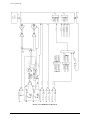
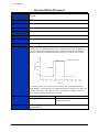
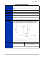
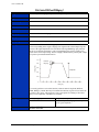
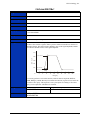
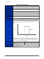
1
VM2601
80 MSa/S, 14-BIT DIGITIZER/IF RECEIVER
VM2602
40 MSa/S, 14-BIT DIGITIZER
VM2603
20 MSa/S, 14-BIT DIGITIZER
USER’S
MANUAL
P/N: 82-0063-000
Released June 15, 2010
VXI Technology, Inc.
2031 Main Street
Irvine, CA 92614-6509
(949) 955-1894
bus
VXI Technology, Inc.
2
www.vxitech.com
TABLE OF CONTENTS
INTRODUCTION
TABLE OF CONTENTS ................................................................................................................................................ 3
Certification ........................................................................................................................................................ 7
Warranty ............................................................................................................................................................. 7
Limitation of Warranty ....................................................................................................................................... 7
Restricted Rights Legend .................................................................................................................................... 7
DECLARATION OF CONFORMITY ............................................................................................................................... 7
GENERAL SAFETY INSTRUCTIONS ............................................................................................................................. 8
Terms and Symbols ............................................................................................................................................ 8
Warnings ............................................................................................................................................................. 8
SUPPORT RESOURCES.............................................................................................................................................. 10
SECTION 1 ................................................................................................................................................................... 11
INTRODUCTION ....................................................................................................................................................... 11
Overview........................................................................................................................................................... 11
Features ............................................................................................................................................................. 13
Data Acquisition ............................................................................................................................................... 13
Programming and Data Access ......................................................................................................................... 13
Calibration ........................................................................................................................................................ 14
Front Panel Connectors ..................................................................................................................................... 14
VM260x Specifications .................................................................................................................................... 16
SECTION 2 ................................................................................................................................................................... 19
PREPARATION FOR USE ........................................................................................................................................... 19
Installation ........................................................................................................................................................ 19
Calculating System Power and Cooling Requirements..................................................................................... 19
Setting the Chassis Backplane Jumpers ............................................................................................................ 20
Setting the Logical Address .............................................................................................................................. 20
SECTION 3 ................................................................................................................................................................... 21
PROGRAMMING ....................................................................................................................................................... 21
Introduction....................................................................................................................................................... 21
Notation ............................................................................................................................................................ 22
APPLICATION EXAMPLES ........................................................................................................................................ 23
SCPI Programming Example ............................................................................................................................ 23
Register Access Example .................................................................................................................................. 24
VXIplug&play Driver Example ........................................................................................................................ 26
SECTION 4 ................................................................................................................................................................... 29
COMMAND DICTIONARY ......................................................................................................................................... 29
Introduction....................................................................................................................................................... 29
Alphabetical Command Listing ........................................................................................................................ 29
Command Dictionary ........................................................................................................................................ 37
COMMON SCPI COMMANDS ................................................................................................................................... 38
*CLS ................................................................................................................................................................. 38
*ESE ................................................................................................................................................................. 39
*ESR? ............................................................................................................................................................... 40
*IDN? ............................................................................................................................................................... 41
*OPC................................................................................................................................................................. 42
*RST ................................................................................................................................................................. 43
*SRE ................................................................................................................................................................. 44
*STB? ............................................................................................................................................................... 45
VM2601/2/3 Preface
3
VXI Technology, Inc.
*TRG ................................................................................................................................................................ 46
*TST? ............................................................................................................................................................... 47
*WAI ................................................................................................................................................................ 48
INSTRUMENT SPECIFIC SCPI COMMANDS ............................................................................................................... 49
ABORt .............................................................................................................................................................. 49
ARM:AUTO ..................................................................................................................................................... 50
ARM[:IMMediate]............................................................................................................................................ 51
ARM:LEVel...................................................................................................................................................... 52
ARM:SLOPe..................................................................................................................................................... 53
ARM:SOURce .................................................................................................................................................. 54
CALCulate:FALL:TIMe ................................................................................................................................... 55
CALCulate:FREQuency? ................................................................................................................................. 56
CALCulate:NDUTy? ........................................................................................................................................ 57
CALCulate:NWIDth? ....................................................................................................................................... 58
CALCulate:PDUTy? ......................................................................................................................................... 59
CALCulate:PERCent:NOVershoot? ................................................................................................................. 60
CALCulate:PERCent:NPReshoot? ................................................................................................................... 61
CALCulate:PERCent:NRINging? .................................................................................................................... 62
CALCulate:PERCent:POVershoot?.................................................................................................................. 63
CALCulate:PERCent:PPReshoot? .................................................................................................................... 64
CALCulate:PERCent:PRINging? ..................................................................................................................... 65
CALCulate:PERiod? ......................................................................................................................................... 66
CALCulate:PWIDth? ........................................................................................................................................ 67
CALCulate:RISE:TIMe? .................................................................................................................................. 68
CALCulate:VOLTage:AMPLitude? ................................................................................................................. 69
CALCulate:VOLTage:HIGH? .......................................................................................................................... 70
CALCulate:VOLTage:LOW? ........................................................................................................................... 71
CALCulate:VOLTage:MAXimum? ................................................................................................................. 72
CALCulate:VOLTage:MEAN? ........................................................................................................................ 73
CALCulate:VOLTage:MINimum? ................................................................................................................... 74
CALCulate:VOLTage:NOVershoot?................................................................................................................ 75
CALCulate:VOLTage:NPReshoot? .................................................................................................................. 76
CALCulate:VOLTage:NRINging? ................................................................................................................... 77
CALCulate:VOLTage:POVershoot? ................................................................................................................ 78
CALCulate:VOLTage:PPReshoot? .................................................................................................................. 79
CALCulate:VOLTage:PRINging? .................................................................................................................... 80
CALCulate:VOLTage:PTPeak?........................................................................................................................ 81
CALCulate:VOLTage:RMS? ........................................................................................................................... 82
CALibration:ADC:GAIN ................................................................................................................................. 83
CALibration:ADC:OFFSet ............................................................................................................................... 84
CALibration:COUNt? ....................................................................................................................................... 85
CALibration:DAC:GAIN ................................................................................................................................. 86
CALibration:DAC:OFFSet ............................................................................................................................... 87
CALibration:DEFault ....................................................................................................................................... 88
CALibration:RESet ........................................................................................................................................... 89
CALibration:SECure:CODE............................................................................................................................. 90
CALibration:SECure[:STATe] ......................................................................................................................... 91
CALibration:STORe ......................................................................................................................................... 92
COMBine:FEED ............................................................................................................................................... 93
CONFigure? ...................................................................................................................................................... 94
CONFigure:ADC .............................................................................................................................................. 95
CONFigure:FALL:TIMe .................................................................................................................................. 96
CONFigure:FREQuency ................................................................................................................................... 97
CONFigure:HORizontal:RESolution................................................................................................................ 98
CONFigure:NDUTy ......................................................................................................................................... 99
CONFigure:NWIDth ...................................................................................................................................... 100
CONFigure:PDUTy ........................................................................................................................................ 101
4
VM2601/2/3 Preface
www.vxitech.com
CONFigure:PERCent:NOVershoot ................................................................................................................ 102
CONFigure:PERCent:NPReshoot .................................................................................................................. 103
CONFigure:PERCent:NRINging .................................................................................................................... 104
CONFigure:PERCent:POVershoot ................................................................................................................. 105
CONFigure:PERCent:PPReshoot ................................................................................................................... 106
CONFigure:PERCent:PRINging .................................................................................................................... 107
CONFigure:PERiod ........................................................................................................................................ 108
CONFigure:PWIDth ....................................................................................................................................... 109
CONFigure:RISE:TIMe.................................................................................................................................. 110
CONFigure:SAR:TIMe................................................................................................................................... 111
CONFigure:SAR:TIMe? ................................................................................................................................. 112
CONFigure:VOLTage:AMPLitude ................................................................................................................ 113
CONFigure:VOLTage:HIGH ......................................................................................................................... 114
CONFigure:VOLTage:LOW .......................................................................................................................... 115
CONFigure:VOLTage:MAXimum ................................................................................................................. 116
CONFigure:VOLTage:MEAN........................................................................................................................ 117
CONFigure:VOLTage:MINimum .................................................................................................................. 118
CONFigure:VOLTage:NOVershoot ............................................................................................................... 119
CONFigure:VOLTage:NPReshoot ................................................................................................................. 120
CONFigure:VOLTage:NRINging .................................................................................................................. 121
CONFigure:VOLTage:POVershoot................................................................................................................ 122
CONFigure:VOLTage:PPReshoot .................................................................................................................. 123
CONFigure:VOLTage:PRINging ................................................................................................................... 124
CONFigure:VOLTage:PTPeak ....................................................................................................................... 125
CONFigure:VOLTage:RMS ........................................................................................................................... 126
CONTrol:IPOWer? ......................................................................................................................................... 127
FETCh? ........................................................................................................................................................... 128
INITiate:DELay .............................................................................................................................................. 129
INITiate[:IMMediate] ..................................................................................................................................... 130
INPut:COUPling ............................................................................................................................................. 131
INPut:FILTer:FREQuency ............................................................................................................................. 132
INPut:FILTer:STATe ..................................................................................................................................... 133
INPut:IMPedance............................................................................................................................................ 134
INPut:OFFSet ................................................................................................................................................. 135
INPut:RANGe................................................................................................................................................. 136
INPut:SOURce................................................................................................................................................ 137
MEASure:FALL:TIMe? ................................................................................................................................. 138
MEASure:FREQuency? .................................................................................................................................. 139
MEASure:NDUTy? ........................................................................................................................................ 140
MEASure:NWIDth? ....................................................................................................................................... 141
MEASure:PDUTy? ......................................................................................................................................... 142
MEASure:PERCent:NOVershoot? ................................................................................................................. 143
MEASure:PERCent:NPReshoot? ................................................................................................................... 144
MEASure:PERCent:NRINging? ..................................................................................................................... 145
MEASure:PERCent:POVershoot? .................................................................................................................. 146
MEASure:PERCent:PPReshoot? .................................................................................................................... 147
MEASure:PERCent:PRINging? ..................................................................................................................... 148
MEASure:PERiod? ......................................................................................................................................... 149
MEASure:PWIDth? ........................................................................................................................................ 150
MEASure:RISE:TIMe?................................................................................................................................... 151
MEASure:VOLTage:AMPLitude? ................................................................................................................. 152
MEASure:VOLTage:HIGH? .......................................................................................................................... 153
MEASure:VOLTage:LOW? ........................................................................................................................... 154
MEASure:VOLTage:MAXimum?.................................................................................................................. 155
MEASure:VOLTage:MEAN? ........................................................................................................................ 156
MEASure:VOLTage:MINimum? ................................................................................................................... 157
MEASure:VOLTage:NOVershoot? ................................................................................................................ 158
VM2601/2/3 Preface
5
VXI Technology, Inc.
MEASure:VOLTage:NPReshoot? .................................................................................................................. 159
MEASure:VOLTage:NRINging? ................................................................................................................... 160
MEASure:VOLTage:POVershoot? ................................................................................................................ 161
MEASure:VOLTage:PPReshoot? ................................................................................................................... 162
MEASure:VOLTage:PRINging? .................................................................................................................... 163
MEASure:VOLTage:PTPeak? ........................................................................................................................ 164
MEASure:VOLTage:RMS? ............................................................................................................................ 165
READ? ............................................................................................................................................................ 166
ROSCillator:FREQuency ................................................................................................................................ 167
ROSCillator:SOURce ..................................................................................................................................... 168
SAMPle:CLOCk:FREQuency ........................................................................................................................ 169
SAMPle:CLOCk:SOURce .............................................................................................................................. 170
SWEep:COUNt ............................................................................................................................................... 171
SWEep:POINts ............................................................................................................................................... 172
SWEep:TINTerval .......................................................................................................................................... 173
SYNChronize:MODE ..................................................................................................................................... 174
SYNChronize:STATe ..................................................................................................................................... 175
TRIGger:DELay ............................................................................................................................................. 176
TRIGger[:IMMediate] .................................................................................................................................... 177
TRIGger:LEVel .............................................................................................................................................. 178
TRIGger:SLOPe ............................................................................................................................................. 179
TRIGger:SOURce ........................................................................................................................................... 180
TRIGger:STATe? ........................................................................................................................................... 181
REQUIRED SCPI COMMANDS ................................................................................................................................ 182
STATus:OPERation:CONDition? .................................................................................................................. 182
STATus:OPERation:ENABle ......................................................................................................................... 183
STATus:OPERation[:EVENt]? ...................................................................................................................... 184
STATus:PRESet ............................................................................................................................................. 185
STATus:QUEStionable:CONDition? ............................................................................................................. 186
STATus:QUEStionable:ENABle .................................................................................................................... 187
STATus:QUEStionable[:EVENt]? ................................................................................................................. 188
SYSTem:ERRor? ............................................................................................................................................ 189
SYSTem:VERSion?........................................................................................................................................ 190
ERROR MESSAGES ................................................................................................................................................ 191
APPENDIX A .............................................................................................................................................................. 195
NOISE SPECIFICATION ........................................................................................................................................... 195
How RMS Noise is Calculated ....................................................................................................................... 195
INDEX ........................................................................................................................................................................ 197
6
VM2601/2/3 Preface
www.vxitech.com
CERTIFICATION
VXI Technology, Inc. certifies that this product met its published specifications at the time of shipment from the
factory. VTI further certifies that its calibration measurements are traceable to the United States National Institute of
Standards and Technology (formerly National Bureau of Standards), to the extent allowed by that organization’s
calibration facility and to the calibration facilities of other International Standards Organization members.
WARRANTY
The product referred to herein is warranted against defects in material and workmanship for a period of three years
from the receipt date of the product at customer’s facility. The sole and exclusive remedy for breach of any warranty
concerning these goods shall be repair or replacement of defective parts or a refund of the purchase price, to be
determined at the option of VTI.
For warranty service or repair, this product must be returned to a VXI Technology authorized service center. The
product shall be shipped prepaid to VTI and VTI shall prepay all returns of the product to the buyer. However, the
buyer shall pay all shipping charges, duties, and taxes for products returned to VTI from another country.
VTI warrants that its software and firmware designated by VTI for use with a product will execute its programming
when properly installed on that product. VTI does not however warrant that the operation of the product or software
or firmware will be uninterrupted or error free.
LIMITATION OF WARRANTY
The warranty shall not apply to defects resulting from improper or inadequate maintenance by the buyer, buyersupplied products or interfacing, unauthorized modification or misuse, operation outside the environmental
specifications for the product or improper site preparation or maintenance.
VXI Technology, Inc. shall not be liable for injury to property other than the goods themselves. Other than the
limited warranty stated above, VXI Technology, Inc. makes no other warranties, express, or implied, with respect to
the quality of product beyond the description of the goods on the face of the contract. VTI specifically disclaims the
implied warranties of merchantability and fitness for a particular purpose.
RESTRICTED RIGHTS LEGEND
Use, duplication or disclosure by the Government is subject to restrictions as set forth in subdivision (b)(3)(ii) of the
Rights in Technical Data and Computer Software clause in DFARS 252.227-7013.
VXI Technology, Inc.
2031 Main Street
Irvine, CA 92614-6509 U.S.A.
VM2601/2/3 Preface
7
www.vxitech.com
DECLARATION OF CONFORMITY
Declaration of Conformity According to ISO/IEC Guide 22 and EN 45014
MANUFACTURER’S NAME
VXI Technology, Inc.
MANUFACTURER’S ADDRESS
2031 Main Street
Irvine, California 92614-6509
PRODUCT NAME
(VM2601) 80 MSa/s Digitizer & IF Receiver
(VM2602) 40 MSa/s Digitizer
(VM2603) 20 MSa/s Digitizer
MODEL NUMBER(S)
VM2601/VM2602/VM2603
PRODUCT OPTIONS
All
PRODUCT CONFIGURATIONS
All
VXI Technology, Inc. declares that the aforementioned product conforms to the requirements of
the Low Voltage Directive 73/23/EEC and the EMC Directive 89/366/EEC (inclusive 93/68/EEC)
and carries the “CE” mark accordingly. The product has been designed and manufactured
according to the following specifications:
SAFETY
EN61010 (2001)
EMC
EN61326 (1997 w/A1:98) Class A
CISPR 22 (1997) Class A
VCCI (April 2000) Class A
ICES-003 Class A (ANSI C63.4 1992)
AS/NZS 3548 (w/A1 & A2:97) Class A
FCC Part 15 Subpart B Class A
EN 61010-1:2001
The product was installed into a C-size VXI mainframe chassis and tested in a typical configuration.
I hereby declare that the aforementioned product has been designed to be in compliance with the relevant sections
of the specifications listed above as well as complying with all essential requirements of the Low Voltage Directive.
September 2006
Steve Mauga, QA Manager
VM2601/2/3 Preface
7
VXI Technology, Inc.
GENERAL SAFETY INSTRUCTIONS
Review the following safety precautions to avoid bodily injury and/or damage to the product.
These precautions must be observed during all phases of operation or service of this product.
Failure to comply with these precautions or with specific warnings elsewhere in this manual
violates safety standards of design, manufacture, and intended use of the product.
Service should only be performed by qualified personnel.
TERMS AND SYMBOLS
These terms may appear in this manual:
WARNING
Indicates that a procedure or condition may cause bodily injury or death.
CAUTION
Indicates that a procedure or condition could possibly cause damage to
equipment or loss of data.
These symbols may appear on the product:
ATTENTION - Important safety instructions
Frame or chassis ground
Indicates that the product was manufactured after August 13, 2005. This mark is
placed in accordance with EN 50419, Marking of electrical and electronic
equipment in accordance with Article 11(2) of Directive 2002/96/EC (WEEE).
End-of-life product can be returned to VTI by obtaining an RMA number. Fees
for take-back and recycling will apply if not prohibited by national law.
WARNINGS
Follow these precautions to avoid injury or damage to the product:
8
Use Proper Power Cord
To avoid hazard, only use the power cord specified for this product.
Use Proper Power Source
To avoid electrical overload, electric shock or fire hazard, do not
use a power source that applies other than the specified voltage.
Use Proper Fuse
To avoid fire hazard, only use the type and rating fuse specified for
this product.
VM2601/2/3 Preface
www.vxitech.com
WARNINGS (CONT.)
Avoid Electric Shock
To avoid electric shock or fire hazard, do not operate this product
with the covers removed. Do not connect or disconnect any cable,
probes, test leads, etc. while they are connected to a voltage source.
Remove all power and unplug unit before performing any service.
Service should only be performed by qualified personnel.
Ground the Product
This product is grounded through the grounding conductor of the
power cord. To avoid electric shock, the grounding conductor must
be connected to earth ground.
Operating Conditions
To avoid injury, electric shock or fire hazard:
Do not operate in wet or damp conditions.
Do not operate in an explosive atmosphere.
Operate or store only in specified temperature range.
Provide proper clearance for product ventilation to prevent
overheating.
DO NOT operate if any damage to this product is suspected.
Product should be inspected or serviced only by qualified
personnel.
Improper Use
The operator of this instrument is advised that if the equipment is
used in a manner not specified in this manual, the protection
provided by the equipment may be impaired.
Conformity is checked by inspection.
VM2601/2/3 Preface
9
VXI Technology, Inc.
SUPPORT RESOURCES
Support resources for this product are available on the Internet and at VTI Instruments customer
support centers.
VTI Instruments Corp.
World Headquarters
VTI Instruments Corp.
2031 Main Street
Irvine, CA 92614-6509
Phone: (949) 955-1894
Fax: (949) 955-3041
VTI Instruments
Cleveland Instrument Division
5425 Warner Road
Suite 13
Valley View, OH 44125
Phone: (216) 447-8950
Fax: (216) 447-8951
VTI Instruments
Lake Stevens Instrument Division
3216 Wetmore Avenue, Suite 1
Everett, WA 98201
Phone: (949) 955-1894
Fax: (949) 955-3041
VTI Instruments, Pvt. Ltd.
Bangalore Instrument Division
642, 80 Feet Road
Koramangala IV Block
Bangalore – 560 034
India
Phone: +91 80 4040 7900
Phone: +91 80 4162 0200
Fax: +91 80 4170 0200
Technical Support
Phone: (949) 955-1894
Fax: (949) 955-3041
E-mail: [email protected]
Visit http://www.vtiinstruments.com for worldwide support sites and service plan information.
10
VM2601/2/3 Preface
www.vxitech.com
SECTION 1
INTRODUCTION
OVERVIEW
The VM2601, VM2602, and VM2603 (refered to as the VM260x) modules are high-resolution,
high-speed digitizers. All three modules have Digital Storage Oscilloscope (DSO) functionality. In
addition, the VM2601 also incorporates an Intermediate Frequency Receiver (IFR) function. This
makes it ideal for applications in medical, automotive, semi-conductor, avionics, and
communication test. The VM260x modules are a message-based device with a SCPI command set
to simplify programming and configuration and register access to provide high-speed data
throughput. Each module has either an 80 MSample/s (MSa/s) (VM2601), 40 MSa/s (VM2602),
or 20 MSa/s (VM2603) ADC to support DSO applications. In addition, the DSO input can be
routed to a 10 MSa/s ADC to support DC accurate low-frequency voltage measurements. A
16 MSa memory provides ample storage for even the most demanding test program. The DSO
input features programmable impedance, ac, or dc coupling and a low-pass filter (LPF) with
programmable corner frequencies.
This module is part of the VMIP™ family of instruments and can be combined with up to two
other modules (e.g., 6.5 digit DMM, 50 MSa/s AWG, 1 ns counter/timer) to form a high-density
VXIbus instrument. Three VM2601/2/3s can be installed in a single-wide C-size module
providing three independent 80/40/20 MSa/s digitzer channels.
Error! Objects cannot be created from editing field codes.
FIGURE 1-1: VMIP™ PLATFORM
VM2601/2/3 Introduction
11
www.vxitech.com
NOTE
With the exception of sample rate and IF receiver capabilities, all three VM260x modules perform
in the same manner. The VM2601 will be referenced thoughout the manual and, when exceptions
exist, they will be noted.
FEATURES
•
•
•
•
•
•
•
•
•
•
Up to 80 MHz bandwidth for DSO (no filter) and 100 MHz for IFR (VM2601 only) – ideal
for HF and IF frequencies
Up to 80 MSa/s sample rate with pre and post trigger capability
±0.5 V, ±1.0 V, ±2 V, ±5.0 V, ±10.0 V, and ±20 V input ranges (DSO input)
50 Ω, 75 Ω, 150 Ω, or 1 MΩ input impedance, with ac or dc coupling (DSO input)
Software selectable low-pass filter (DSO input)
Built-in pulse parameter measurements
Up to three independent channels per C-size card
Auto re-arm capability for storing multiple waveforms with pre-trigger data
Sleep mode reduces power consumption when not in use
Dual channel synchronization for precise I/O
DATA ACQUISITION
The input data is acquired when a conversion trigger event occurs from one of the four following
methods:
1. Trigger source from the front panel input: This input has a ±4 V input range and may be
programmed to trigger on either the rising or falling edge of this signal and at specified voltage
levels with 12-bit resolution and accurate to 1% of full scale.
2. Trigger source from the VXI TTL trigger bus: Any one of the eight TTL trigger bus lines may
be selected as the trigger source. The unit may be programmed to trigger on either the rising or
falling edge of this signal.
3. Trigger upon receipt of a word serial command: When this mode is selected, the ADC will
convert when a word-serial command is received by the instrument.
4. Trigger from the input channel: The input channel can be selected to trigger the board. It can
be programmed to trigger during a rising or falling edge and may also trigger at specified
voltage levels with 12-bit resolution and accurate to 1% of full scale.
Memory can be segmented such that sequential trigger events can be stored without forcing the
device to rearm via software or waiting for the previous samples to be offloaded. Both pre-trigger
and post-trigger samples can be acquired in up to eight segments. When the instrument is
configured for greater than eight segments, only post-trigger samples will be stored. The device
can support up to 65,536 segments. Since three VM2601 modules can be accommodated on a
single C-size VXIbus card, three differential channels can all be operating and triggering
independently. For example, one can be acquiring data while another is waiting for a trigger.
PROGRAMMING AND DATA ACCESS
As is true with most complex VXI Technology instrumentation, the VM2601give the user the
ability to access the device using the VXI message-based interface as well as utilizing direct
register access for fast data throughput. The SCPI (message based) command set is used for
instrument configuration, measurement configuration, and to query the results of the
measurements. Register access is used to transfer the raw digitizer data from the instrument to the
host. With modern host computers and interfaces, all 16 MSa can be transferred in just a few
seconds. Measurements are configured and initiated by SCPI commands from the host.
VM2601/2/3 Introduction
13
VXI Technology, Inc.
Measurement data is output in response to a query from the host. This considerably reduces test
program development and improves overall test times.
CALIBRATION
The calibration constants used to correct the data values are stored in non-volatile memory. These
constants are determined when the instrument is calibrated and can be set or queried by word
serial command. This eliminates the need for removing covers from the unit and allows for
automated calibration.
FRONT PANEL CONNECTORS
+ INPUT (J111)
Positive differential input for DSO channel (channel A+)
- INPUT (J112)
ACC/ERR
FAIL
J105
Negative differential input for DSO channel (channel A-)
IF INPUT (J113)
J106
Single-ended IFR input (channel B)
J107
NOTE This connector is covered on the VM2602 and VM2603 modules.
J108
J109
TRIGGER/GP0 INPUT (J114)
J110
ACC/ERR
External Trigger Input/GP0 marker input
FAIL
J111
ARM/GP1 INPUT (J115)
External Arm Input/GP1 marker input
J112
EXTERNAL CLOCK INPUT (J116)
J113
External Sample Clock
J114
J115
J116
ACC/ERR
FAIL
J117
J118
J119
J120
J121
J122
Note: Front panel J designators vary with the
type(s) of module(s) installed and with the
instrument’s position in the VMIP carrier.
FIGURE 1-2: FRONT PANEL LAYOUT
14
VM2601/2/3 Introduction
75 Ω
75 Ω
EXT_ CL K_ LVL
EXT_ CL K_ IN
EXT_ AR M_ LVL
EXT_ AR M_ IN
EXT_ TRIG_ LVL
EXT_ TRIG
50 Ω
D SO_C Hn l–
50 Ω
150 Ω
150 Ω
DAC
DAC
DAC
–
+
–
+
–
+
DSO_CHnI+
DAC
DIFF TO
SINGLE
EXT_CLK
EXT_ARM
EXT TRIG
TRIG_LVL
÷ 10
÷1
÷ 10
÷1
–
2.5X
LPF 2
LPF 1
OFF SET_LVL
–
+
+
–
50 Ohm
REF_LVL
DAC
1x, 2x, 4x
VXI_10 MHz
SYNC_ARM_IN
SYNC_TRIG_IN
SYNC_IN
SYNC_CLK_IN
SYNC_ARM_OUT
SYNC_TRIG_OUT
SYNC_OUT
PPL
INPUT TRIG
REFERENCE
ADJ
DC_VERTICAL
SYNC_CLK_OUT
DAC
OFFSET
ADJ
–
+
+
IFR (only on t he VM2 60 1)
80 MHz INT
SYNC_ARM_INP
SYNC_TRIG_INP
SYNC_INP
SYNC_CLK_INP
SYNC_ARM_OUT
SYNC_TRIG_OUT
SYNC_OUT
SYS_CLK_OUT
SIN GL E T O
DIF F
SINGLE TO
D IFF
–
+
–
TTL_2_LVDS
+
VM2601/2/3 Introduction
LVDS _2_TTL
EXT_CLK_LVL
EXT_ARM_LVL
EXT_TRIG_LVL
OFFSET_LVL
TRIG_LVL
REF_LVL
SYS_CLK
SLOW
ADC
14 BITS
1 kHz ÷ 10 MHz
80 MHz
FAST
ADC
14 BITS
ARM
TRIG
16 bit, 10 MHz
VMIP
CARRIER
VXIBUS
SYNC
EXT
IMED
SYNC T RIG
VXIBUS
IMMED
EXT
INPUT
GLUE LOGIC
16 bit, 10 MHz
32/64 MB
DDR
www.vxitech.com
FIGURE 1-3: VM260X BLOCK DIAGRAM
15
VXI Technology, Inc.
VM260X SPECIFICATIONS
ANALOG INPUT
CHANNELS
DSO
IFR (VM2601 only)
1 differential or single-ended (channels A+ and A-)
1 single-ended (channel B)
CONNECTORS
VM2601
VM2602/3
6 SMB connectors
5 SMB connectors
RESOLUTION
14 bits
FULL-SCALE INPUT RANGES
DSO input
IFR input
±0.5 V, ±1.0 V and ±2.0 V; ±5.0 V, ±10 V, and ±20 V∗
±0.5 V
MAXIMUM SAMPLE RATE (SRMAX)
DSO input
VM2601
VM2602
VM2603
IFR input (VM2601 only)
SAMPLE RATE RESOLUTION
80 MSa/s
40 MSa/s
20 MSa/s
80 MSa/s
(SR MAX ) , where n is an integer divider set by SAMPle:CLOCk:FREQuency
n
BANDWIDTH
40 MHz, LPF On (VM2601)
20 MHz, LPF On (VM2601/2)
10 MHz, LPF On (VM2602/3)
5 MHz, LPF On (VM2603)
40 MHz
20 MHz
10 MHz
5 MHz
MEMORY
Standard (VM2601/2/3)
Option (VM2601/2/3)
16 MSa
32 MSa
MEMORY SEGMENTS
With pre-trigger data
Without pre-trigger data
8 segments
64k segments
IMPEDANCE
DSO input
IFR input
50 Ω, 75 Ω, 150 Ω, or 1 MΩ
50 Ω
MAXIMUM NON-DESTRUCTIVE INPUT
1 MΩ range
50 Ω, 75 Ω, 150 Ω ranges
±50 V common mode
±5 V common mode
INPUT COUPLING
DSO input
IFR input
ac/dc
dc
CAPACITANCE
40 pF maximum
COMMON MODE REJECTION RATIO (CMRR)
DC to 20 kHz @ ±0.5 V input range
All other input ranges up to SRMAX/2
≥ 60 dB
≥ 30 dB
OFFSET ADJUSTMENT
±50% of full-scale
DC ACCURACY
DSO FAST*
DSO SLOW*
IFR (VM2601 only)
∗
±1% of range
±0.5% of input, ±0.1% of range
±1% of range
*50 Ω/75 Ω/150 Ω/1 MΩ impedance
Note that the input voltage should not exceed 8 V dc or 8 V rms when the 50 Ω, 75 Ω, or 150 Ω input impedance is selected.
16
VM2601/2/3 Introduction
www.vxitech.com
ANALOG INPUT
AC AMPLITUDE ACCURACY
< 1 MHz
1 MHz to 20 MHz
20 MHz to 40 MHz
±0.1 dB
±0.5 dB
±2.5 dB
FREQUENCY FLATNESS
Low input ranges (All)
dc to 5 MHz
5 MHz to 30 MHz
High input ranges
dc to 5 MHz
5 MHz to 30 MHz
No filter, -1 dB (full scale) @ 50 Ω
±0.1 dB
±0.5 dB
No filter, -1 dB (full scale) @ 50 Ω
±0.5 dB
±1 dB
LOW-PASS FILTER
Filter Type
VM2601
VM2602
VM2603
3-pole Bessel
None, 20 MHz, 40 MHz
None, 10 MHz, 20 MHz
None, 5 MHz, 10 MHz
INTEGRAL NON-LINEARITY
±0.5 LSB typical
SHARED MEMORY SPACE
A32
MISSING CODES
Guaranteed no missing codes
DYNAMIC CHARACTERISTICS
SIGNAL-TO-NOISE PLUS DISTORTION RATIO (S/[N+D])*
0.5 V, 1.0 V & 2.0 V input ranges
5 V, 10 V & 20 V input ranges
69 dB typical, 63 dB minimum
65 dB typical, 60 dB minimum
*20 Hz to 30 MHz, SRMAX low jitter clock
SPURIOUS FREE DYNAMIC RANGE (SFDR)
> 77 dB typical, 75 dB minimum
0.5 V, 5.0 V input ranges*
> 80 dB typical, 77 dB minimum
1.0 V, 10 V input ranges*
> 80 dB typical, 75 dB minimum
2.0 V, 20 V input ranges*
> 77 dB typical, 75 dB minimum
0.5 V, 5.0 V input ranges**
> 77 dB typical, 75 dB minimum
1.0 V, 10 V input ranges**
> 77 dB typical, 75 dB minimum
2.0 V, 20 V input ranges**
IF input (excluding harmonics)
> 80 dB typical, 75 dB minimum (VM2601 only)
** 20 Hz to 1 MHz, 10 MSa/s, 20 MHz LPF on, FFT size = 16,384 (VM2601/2)
** 1 MHz to 10 MHz, SRMAX, (SRMAX/2) low-pass Filter ON (VM2602/3)
RMS NOISE
(SRMAX/2) bandwidth @ 50 Ω
Source impedance, 0.5 V range
250 µV rms maximum (IFR) (exclusive of any offset)∗
SIGNAL-TO-NOISE RATIO (SNR)
All inputs, all ranges
∗
> 62 dB
See Appendix A for information on calculating RMS noise.
VM2601/2/3 Introduction
17
VXI Technology, Inc.
ARMING, TRIGGERING, AND CLOCKING
TRIGGER SOURCE
Channel Input, EXT input, Serial Word Command, TTLT bus, Sync
EXTERNAL TRIGGER
Impedance
Amplitude
Level Accuracy
10 kΩ
±4 V
±5 mV
MAXIMUM PRE-TRIGGER SAMPLES
Available memory – 1
TRIGGER DELAY
0 – 3,600 seconds
INTERNAL CLOCK SOURCE
CLK10
INTERNAL CLOCK ACCURACY
CLK10
EXTERNAL CLOCK MAXIMUM FREQUENCY
80 MHz
40 MHz
20 MHz
VM2601
VM2602
VM2603
EXTERNAL CLOCK IMPEDANCE
50 Ω
ARM SOURCE
EXT, IMM, SYNC, TTLT<0-7>
EXTERNAL ARM
Impedance
Amplitude
Resolution
10 kΩ
±4V
5 mV
BUILT-IN MEASUREMENT FUNCTIONS
MEASUREMENT FUNCTION
•
•
•
•
•
•
•
•
•
•
•
•
•
•
Period
Rise/Fall Time
Negative/Positive Pulse Width
V rms/V cycle rms
V mean
V high
V max
Frequency
Negative/Positive Duty Cycle
Negative/Positive Overshoot/Preshoot
V peak
V amplitude
V low
V min
ENVIRONMENTAL
OPERATING TEMPERATURE RANGE
0 °C – 60 °C
CALIBRATION TEMPERATURE
25 °C
POWER AND COOLING REQUIREMENTS
VOLTAGE
1.86 A (0.6 A)*
+5 V
0.062 A (0.03 A)
-5.2 V
0A
(0 A)
+2 V
0A
(0 A)
+24 V
2A
(0 A)
-24 V
0.25 A (0 A)
+12 V
0.24 A (0 A)
-12 V
* Values in parenthesis represent values in stand by mode
18
VM2601/2/3 Introduction
www.vxitech.com
SECTION 2
PREPARATION FOR USE
INSTALLATION
When the VM2601 is unpacked from its shipping carton, the contents should include the following
items:
(1) VM2601/2/3 VXIbus module
(1) VM2601/2/3 Module User’s (this manual)
All components should be immediately inspected for damage upon receipt of the unit.
Once the VM2601 is assessed to be in good condition, it may be installed into an appropriate
C-size or D-size VXIbus chassis in any slot other than slot 0. The chassis should be checked to
ensure that it is capable of providing adequate power and cooling for the VM2601. Once the
chassis is found adequate, the VM2601’s logical address and the backplane jumpers of the chassis
should be configured before the VM2601’s installation.
CALCULATING SYSTEM POWER AND COOLING REQUIREMENTS
The power and cooling requirements of the VM2601 are given in the specification table in
Section 1 of this manual. It is imperative that the chassis provide adequate power and cooling for
this module. Referring to the chassis user manual, confirm that the power budget for the system
(the chassis and all modules installed therein) is not exceeded and that the cooling system can
provide adequate airflow at the specified backpressure.
It should be noted that if the chassis cannot provide adequate power to the module, the instrument
may not perform to specification or possibly not operate at all. In addition, if adequate cooling is
not provided, the reliability of the instrument will be jeopardized and permanent damage may
occur. Damage found to have occurred due to inadequate cooling voids the warranty on the
instrument in question.
VM2601/2/3 Preparation for Use
19
VXI Technology, Inc.
SETTING THE CHASSIS BACKPLANE JUMPERS
Please refer to the chassis user manual for further details on setting the backplane jumpers.
SETTING THE LOGICAL ADDRESS
The logical address of the VM2601 is set by a single 8-position DIP switch located near the
module’s backplane connectors (this is the only switch on the module). The switch is labeled with
positions 1 through 8 and with an ON position. A switch pushed toward the ON legend will
signify logic 1; switches pushed away from the ON legend will signify logic 0. The switch located
at position 1 is the least significant bit while the switch located at position 8 is the most significant
bit. See Figure 2-1 for examples of setting the logical address switch.
ON
ON
1 2 3 4 5 6 7 8
1 2 3 4 5 6 7 8
SET TO 4
SET TO 8
ON
ON
1 2 3 4 5 6 7 8
1 2 3 4 5 6 7 8
SET TO 168
SET TO 255
(Dynamic)
Switch
Position
Switch
Value
1
2
3
4
5
6
7
8
1
2
4
8
16
32
64
128
FIGURE 2-1: LOGICAL ADDRESS SWITCH-SETTING EXAMPLES
The VMIP may contain three separate instruments and will allocate logical addresses as required
by the VXIbus specification (revisions 1.3 and 1.4). The logical address of the instrument is set on
the VMIP carrier. The VMIP logical addresses must be set to an even multiple of 4 unless
dynamic addressing is used. Switch positions 1 and 2 must always be set to the OFF position.
Therefore, only addresses of 4, 8, 12, 16, ... 252 are allowed. The address switch should be set for
one of these legal addresses and the address for the second instrument (the instrument in the center
position) will automatically be set to the switch set address plus one; while the third instrument
(the instrument in the lowest position) will automatically be set to the switch set address plus two.
If dynamic address configuration is desired, the address switch should be set for a value of 255 (all
switches set to ON). Upon power-up, the slot 0 resource manager will assign the first available
logical addresses to each instrument in the VMIP module.
If dynamic address configuration is desired, the address switch should be set for a value of 255.
Upon power-up, the slot 0 resource manager will assign logical addresses to each instrument in the
VMIP module.
20
VM2601/2/3 Preparation for Use
www.vxitech.com
SECTION 3
PROGRAMMING
INTRODUCTION
The VM2601 is a VXIbus message-based device whose command set is compliant with the
Standard Commands for Programmable Instruments (SCPI) programming language.
All module commands are sent over the VXIbus backplane to the module. Commands may be in
upper, lower, or mixed case. All numbers are sent in ASCII decimal unless otherwise noted.
The module recognizes SCPI commands. SCPI is a tree-structured language based on IEEE
Std 488.2 specifications. It uses the IEEE Std 488.2 Standard command and the device dependent
commands are structured to allow multiple branches off the same trunk to be used without
repeating the trunk. To use this facility, end each branch with a semicolon. For example, SLOPe
and SOURce are both branches off the TRIGger: command trunk and can be combined as
follows:
TRIGger:SLOPe <slope>;SOURce <source>
The above command is the same as these two commands:
TRIGger:SLOPe <slope>
TRIGger:SOURce <source>
See the Standard Commands for Programmable Instruments (SCPI) Manual, Volume 1: Syntax &
Style, Section 6, for more information.
The SCPI commands in this section are listed in upper and lower case. Character case is used to
indicate different forms of the same command. Keywords can have both a short form and a long
form (some commands only have one form). The short form uses just the keyword characters in
uppercase. The long form uses the keyword characters in uppercase plus the keyword characters in
lowercase. Either form is acceptable. Note that there are no intermediate forms. All characters of
the short form or all characters of the long form must be used. Short forms and long forms may be
freely intermixed. The actual commands sent can be in upper case, lower case, or mixed case (case
is only used to distinguish short and long form for the user). As an example, these commands are
all correct and all have the same effect:
TRIGger:SLOPe <slope>
trigger:slope <slope>
TRIGGER:SLOPE <slope>
TRIG:SLOPe <slope>
TRIGger:SLOP <slope>
TRIG:SLOP <slope>
trig:slop <slope>
VM2601/2/3 Programming
21
VXI Technology, Inc.
The following command is not correct because it uses part of the long form of TRIGger, but not
all the characters of the long form:
trigg:slop <slope>
incorrect syntax - extra "g"
All of the SCPI commands also have a query form unless otherwise noted. Query forms contain a
question mark (?). The query form allows the system to ask what the current setting of a parameter
is. The query form of the command generally replaces the parameter with a question mark (?).
Query responses do not include the command header. This means only the parameter is returned:
no part of the command or "question" is returned.
NOTATION
Keywords or parameters enclosed in square brackets ([ ]) are optional. If the optional part is a
keyword, the keyword can be included or left out. Omitting an optional parameter will cause its
default to be used. If using the optional parameter, the square brackets are omitted from the
command or query.
Parameters are enclosed by angle brackets (< >). Braces ({ }) or curly brackets, are used to enclose
one or more parameters that may be included zero or more times. A vertical bar (|), read as "or," is
used to separate parameter alternatives.
22
VM2601/2/3 Programming
www.vxitech.com
APPLICATION EXAMPLES
SCPI PROGRAMMING EXAMPLE
This section contains examples of using SCPI command strings for programming the VM2601
module. The code is functional and will contain a brief description of the operation. Note, the
SCPI commands used by the VM2601 are explained in detail in Section 4.
In this example, VM2601 sets the sweep points, sample clock frequency, input range, and trigger
source. It returns the average, maximum, minimum, peak-to-peak voltage, and rms voltage of the
data collected from a previous run.
SWE:POIN 32768
Sets the number of post trigger samples to
32 k.
SAMP:CLOC:FREQ 1E4
Sets the sample rate to 10 kHz.
INP:RANG 20
Sets the input voltage range to ±20 V.
TRIG:SOUR IMM
Sets the input trigger source to IMMediate.
INIT:IMM
Puts the VM2601 into the “waiting for arm”
state.
ARM
Arms the VM2601 module immediately.
TRIG:IMM
Triggers the VM2601 module immediately.
At this point, after 32,768/10,000 seconds, the samples are in the buffer and the CALCulate
commands can be executed.
CALC:VOLT:MEAN?
15.107537
Returns the average data value.
CALC:VOLT:MAX?
19.234100
Returns the maximum data value collected.
CALC:VOLT:MIN?
-12.693521
Returns the minimum data value collected.
CALC:VOLT:PTP?
13.451500
Returns the peak-to-peak value starting at
the trigger point and continuing to the end
of data collected.
CALC:VOLT:RMS?
4.653781
Returns the true rms value starting at the
trigger point and continuing to the end of
the data collected.
VM2601/2/3 Programming
23
VXI Technology, Inc.
REGISTER ACCESS EXAMPLE
The VM2601 module provides hardware register access for fast data transfers. The register map is
shown in Table 3-1.
In order to read the samples, execute an INITiate, ARM, TRIGger sequence as seen in the SCPI
Programming Example above. Then, use viIn16(instHndl, VI_A32_SPACE, offset, &var16bit) for
a single sample or viMoveIn16(instHndl, VI_A32_SPACE, offset, number_of_samples,
array16bit) for multiple samples.
To determine the dc voltage value of any sample:
1) Obtain the ADC gain and offset values from the instrument using the commands
CAL:ADC:GAIN <FAST|SLOW> and CAL:ADC:OFFS? <FAST|SLOW>.
2) Calculate the voltage as follows:
voltage =
((double)(sample value - ADC_Offset) × ADC_Gain × 2.0 × range
16383.0
where ‘range’ is the current input range that has been programmed.
For example, in the 5 V range, for a sample value of 12,684, where ADC_Gain is 1.237854 and
ADC_Offset is 8183:
voltage =
(12684 − 8183)×1.237854 × 2.0 × 0.5 = 0.340083 volts
16383.0
The VM2601 digitizer’s sample memory is mapped into the VXI A32 address space by the VISA
resource manager. When accessing the sample data through a call to viIn16() or viMoveIn16(), it
is not necessary to know the absolute address assigned to the module. VISA uses the session
handle to reference the assigned address space.
24
VM2601/2/3 Programming
www.vxitech.com
TABLE 3-1: A16 MEMORY MAP
3E
3C
3A
38
36
34
32
30
2E
2C
2A
28
26
24
22
20
1E
1C
1A
18
16
14
12
10
E
C
A
8
6
4
2
0
VM2601/2/3 Programming
[A32 Pointer Low]
[A32 Pointer High]
Data Low
Data High
Response [/Data Extended]
Protocol [/Signal] Register
[Offset Register]
Status / Control Register
Device Type
ID Register
25
VXI Technology, Inc.
VXIPLUG&PLAY DRIVER EXAMPLE
This example shows how to access the instrument using the VXIplug&play driver.
// - - - - - - - - - - - - - - - - - - - - - - - - - - - - - - - - - - - - - - - - - - - - - - - - - - - - - - - - - - - - - - - - - - - - - - - - - - - - - - - - - - - - - - - - - - - // vtvm2601_appFunc()
Example of how to access the instrument using the driver
// Parameters:
//
ViSession
instHndl
Session handle issued by the resource manager
//
ViInt16
inputSelect
Selects DSO or IFR input
(For the VM2602 and VM2603, DSO is the only valid selection)
//
ViInt16
adcSelect
If DSO, selects fast or slow ADC
//
ViInt16
rangeSelect
If DSO, selects input range
//
ViInt16
inputCoupling
If DSO, selects input coupling
//
ViReal64
sampleRate
sets the sample rate
//
ViInt32
sampleCount
sets the sample count
//
ViInt16
dPointer[]
points to storage for the data
// Returns:
VI_SUCCESS or error code
// - - - - - - - - - - - - - - - - - - - - - - - - - - - - - - - - - - - - - - - - - - - - - - - - - - - - - - - - - - - - - - - - - - - - - - - - - - - - - - - - - - - - - - - - - - - ViStatus _VI_FUNC vtvm2601_appFunc(ViSession instHndl, ViInt32 inputSelect, ViInt32 adcSelect,
ViInt32 rangeSelect, ViInt32 inputCoupling, ViReal64 sampleRate,
ViInt32 sampleCount, ViInt16 _VI_FAR dPointer[])
{
ViStatus
iStatus;
ViInt32
segNmbr, ramOffs, ptrgCnt;
ViInt32
loopCnt, operCond, daqState;
iStatus = vtvm2601_setInpSour(instHndl, inputSelect);
if(iStatus < VI_SUCCESS)
return(iStatus);
iStatus = vtvm2601_setAdcType(instHndl, adcSelect);
if(iStatus < VI_SUCCESS)
return(iStatus);
iStatus = vtvm2601_setInpRange(instHndl, rangeSelect);
if(iStatus < VI_SUCCESS)
return(iStatus);
iStatus = vtvm2601_setInpCoup(instHndl, inputCoupling);
if(iStatus < VI_SUCCESS)
return(iStatus);
iStatus = vtvm2601_setSclkFreq(instHndl, sampleRate);
if(iStatus < VI_SUCCESS)
return(iStatus);
iStatus = vtvm2601_setSampCnt(instHndl, sampleCount);
if(iStatus < VI_SUCCESS)
return(iStatus);
// select the input
ptrgCnt = sampleCount;
iStatus = vtvm2601_setPreTrig(instHndl, ptrgCnt);
if(iStatus < VI_SUCCESS)
return(iStatus);
// make pre-trigger = sampleCount
iStatus = vtvm2601_initiate(instHndl);
if(iStatus < VI_SUCCESS)
return(iStatus);
iStatus = vtvm2601_cmdArmImme(instHndl);
if(iStatus < VI_SUCCESS)
return(iStatus);
lclDelay((double)ptrgCnt / sampleRate);
// initiate the operation
iStatus = vtvm2601_cmdTrigImme(instHndl);
if(iStatus < VI_SUCCESS)
return(iStatus);
lclDelay((double)sampleCount / sampleRate);
// select the ADC
// set the range
// set the input coupling
// set the sample rate
// set the sample count
// WAIT at least long enough for pre-trig
// WAIT at least long enough for samples
// now, query the machine state
for(loopCnt = 0; loopCnt < 1000; loopCnt++)
{
iStatus = vtvm2601_qryOperCondReg(instHndl, &operCond);
if(iStatus < VI_SUCCESS)
return(iStatus);
if((operCond & vtvm2601_OPER_MEAS) != vtvm2601_OPER_MEAS)
26
VM2601/2/3 Programming
www.vxitech.com
}
break;
iStatus = vtvm2601_abort(instHndl);
if(iStatus < VI_SUCCESS)
return(iStatus);
if(daqState != vtvm2601_DAS_IDLE)
return(vtvm2601_ERR_NOT_READY);
}
// ready or not, abort the operation!
// didn't make it to idle, data not ready!
segNmbr = 0;
// segment number = 0, use the first segment
ramOffs = 0;
// ram offset = 0, first sample from the trigger point
// Now, get the samples!
iStatus = vtvm2601_a32Fetch(instHndl, segNmbr, ramOffs, sampleCount, dPointer);
return(iStatus);
VM2601/2/3 Programming
27
VXI Technology, Inc.
28
VM2601/2/3 Programming
www.vxitech.com
SECTION 4
COMMAND DICTIONARY
INTRODUCTION
This section presents the instrument command set. It begins with an alphabetical list of all the
commands supported by the VM2601 divided into three sections: IEEE 488.2 commands, the
instrument specific SCPI commands, and the required SCPI commands. Each command provides
a brief description of the command’s function, whether the command’s value is affected by the
*RST command, and, if applicable, its *RST value.
The remainder of this section is devoted to describing each command, one per page, in detail. The
description is presented in a regular and systematic manner, assisting the user in the use of each
command. Every command entry describes the exact command and query syntax, the use and
range of parameters, and a complete description of the command’s purpose.
ALPHABETICAL COMMAND LISTING
The following tables provide an alphabetical listing of each command supported by the VM2601
along with a brief description. If an X is found in the column titled *RST, then the value or setting
controlled by this command is possibly changed by the execution of the *RST command. If no X
is found, then *RST has no effect. The *RST column gives the value of each command’s setting
when the unit is powered up or when an *RST command is executed.
VM2601/2/3 Command Dictionary
29
VXI Technology, Inc.
TABLE 4-1: IEEE 488.2 COMMON COMMANDS
Command
*CLS
*ESE
*ESR?
*IDN?
*OPC
*RST
*SRE
*STB?
*TRG
*TST?
*WAI
30
Description
*RST
Clears the Status Register
Sets the Event Status Enable Register
Query the Standard Event Status Register
Query the module identification string
Set the OPC bit in the Event Status Register
Resets the module to a known state
Set the Service Request Enable Register
Query the Status Byte Register
Causes a trigger event to occur
Starts and reports a self-test procedure
Halts execution of commands and queries
*RST Value
N/A
N/A
N/A
N/A
N/A
N/A
N/A
N/A
N/A
N/A
N/A
VM2601/2/3 Command Dictionary
www.vxitech.com
TABLE 4-2: INSTRUMENT SPECIFIC SCPI COMMANDS
Command
ABORt
ARM:AUTO
ARM:LEVel
ARM:SLOPe
ARM:SOURce
ARM:STATe?
ARM[:IMMediate]
CALCulate:FALL:TIMe?
CALCulate:FREQuency?
CALCulate:NDUTy?
CALCulate:NWIDth?
CALCulate:PDUTy?
CALCulate:PERCent:NOVershoot?
CALCulate:PERCent:NPReshoot?
CALCulate:PERCent:NRINging?
CALCulate:PERCent:POVershoot?
CALCulate:PERCent:PPReshoot?
CALCulate:PERCent:PRINging?
CALCulate:PERiod?
CALCulate:PWIDth?
CALCulate:RISE:TIMe?
CALCulate:VOLTage:AMPLitude?
CALCulate:VOLTage:HIGH?
CALCulate:VOLTage:LOW?
CALCulate:VOLTage:MAXimum?
CALCulate:VOLTage:MEAN?
CALCulate:VOLTage:MINimum?
CALCulate:VOLTage:NOVershoot?
CALCulate:VOLTage:NPReshoot?
CALCulate:VOLTage:NRINging?
CALCulate:VOLTage:POVershoot?
CALCulate:VOLTage:PPReshoot?
VM2601/2/3 Command Dictionary
Description
Disarms the VM2601 and stops data sampling.
Enables or disables automatic advancing to the next
buffer and rearming.
Sets the comparator level of the Arm Signal.
Specifies the slope of the Arm Signal.
Sets the Arm Source.
Query returns whether or not the VM2601 is armed.
Advances to the next buffer and arms the unit.
Instructs the device to return the fall time
measurement for the acquired data.
Query that instructs the device to return the
frequency of the digitized data.
Instructs the device to calculate and return the
negative duty cycle for the acquired data.
Returns the negative pulse width measurement for
the acquired data.
Instructs the device to calculate and return the
positive duty cycle for the acquired data.
Returns the negative overshoot as percent of
amplitude
Returns the negative preshoot as percent of
amplitude
Returns the negative ringing as percent of amplitude
Returns the positive overshoot as percent of
amplitude
Returns the positive preshoot as percent of amplitude
Returns the positive ringing as percent of amplitude
Returns the period measurement for the acquired
data.
Query that returns a positive pulse width
measurement.
Returns the rise-time measurement for the acquired
data.
Returns the amplitude measurement for the data
being acquired.
Returns the high voltage value for the acquired data.
Returns the low voltage value for the acquired data.
Returns the maximum voltage value for the acquired
data.
Returns the mean voltage value for the acquired data.
Returns the minimum voltage value for the acquired
data.
Returns the negative overshoot value for the acquired
data.
Returns the negative preshoot value for the acquired
data.
Returns the negative ringing as peak-to-peak volts
Returns the positive overshoot value for the acquired
data.
Returns the positive preshoot value for the acquired
data.
*RST
*RST Value
N/A
X
OFF
X
X
X
0.0
POS
IMMediate
N/A
31
VXI Technology, Inc.
Command
CALCulate:VOLTage:PRINging?
CALCulate:VOLTage:PTPeak?
CALCulate:VOLTage:RMS?
CALibration:ADC:GAIN
CALibration:ADC:OFFSet
CALibration:COUNt?
CALibration:DAC:GAIN
CALibration:DAC:OFFSet
CALibration:DEFault
CALibration:RESet
CALibration:SECure:CODE
CALibration:SECure[:STATe]
CALibration:STORe
COMBine:FEED
CONFigure:ADC
CONFigure:FALL:TIMe
CONFigure:FREQuency
CONFigure:HORizontal:RESolution
CONFigure:NDUTy
CONFigure:NWIDth
CONFigure:PDUTy
CONFigure:PERCent:NOVershoot
CONFigure:PERCent:NPReshoot
CONFigure:PERCent:NRINging
CONFigure:PERCent:POVershoot
CONFigure:PERCent:PPReshoot
CONFigure:PERCent:PRINging
CONFigure:PERiod
32
Description
*RST
Returns the positive ringing as peak-to-peak volts
Returns the peak-to-peak voltage value for the
acquired data.
Returns the root-mean-square (rms) voltage value of
the data being acquired.
To provide an ADC gain factor for measurement
compensation.
To provide an ADC offset value for measurement
compensation.
Tracks the number of times calibration memory has
been written.
To set the calibration factor that compensates for
DAC gain inaccuracies.
To set the calibration factor that compensates for
DAC offset inaccuracies.
Sets all calibration factors to their default values.
Resets all calibration factors to the values stored in
the non-volatile memory (EEPROM).
Sets the code required to disable calibration security.
Enable or disable calibration security.
Stores calibration data into non-volatile memory.
Sets a marker for specified events allowing for easy
reference after acquisition is complete.
Selects between the fast and slow ADCs.
Defines the fall time parameters that will govern
corresponding CALCulate and MEASure commands.
Defines the frequency parameters that will govern
corresponding CALCulate and MEASure commands.
Sets the sample period for the ADC
Defines the negative duty cycle parameters that will
govern corresponding CALCulate and MEASure
commands.
Defines the negative pulse width parameters that will
govern corresponding CALCulate and MEASure
commands.
Defines the positive duty cycle parameters that will
govern corresponding CALCulate and MEASure
commands.
configure to measure negative overshoot as percent
of amplitude
configure to measure negative preshoot as percent of
amplitude
configure to measure negative ringing as percent of
amplitude
configure to measure positive overshoot as percent of
amplitude
configure to measure positive preshoot as percent of
amplitude
configure to measure positive ringing as percent of
amplitude
Defines the period parameters that will govern
corresponding CALCulate and MEASure commands.
*RST Value
1.000
8192
1.000 or
Cal Value
2047 or
Cal Value
X
ON
X
GND
X
FAST
X
100.0 ns
VM2601/2/3 Command Dictionary
www.vxitech.com
Command
CONFigure:PWIDth
CONFigure:RISE:TIMe
CONFigure:SAR:TIMe
CONFigure:SAR:TIMe?
CONFigure:VOLTage:AMPLitude
CONFigure:VOLTage:HIGH
CONFigure:VOLTage:LOW
CONFigure:VOLTage:MAXimum
CONFigure:VOLTage:MEAN
CONFigure:VOLTage:MINimum
CONFigure:VOLTage:NOVershoot
CONFigure:VOLTage:NPReshoot
CONFigure:VOLTage:NRINging
CONFigure:VOLTage:POVershoot
CONFigure:VOLTage:PPReshoot
CONFigure:VOLTage:PRINging
CONFigure:VOLTage:PTPeak
CONFigure:VOLTage:RMS
CONFigure?
CONTrol:IPOWer
FETCh?
INITiate:DELay
INITiate[:IMMediate]
INPut:COUPling
VM2601/2/3 Command Dictionary
Description
Defines the positive pulse width parameters that will
govern corresponding CALCulate and MEASure
commands.
Defines the rise time parameters that will govern
corresponding CALCulate and MEASure commands.
configure the Signal Aberration Region size in
seconds
query the Signal Aberration Region size
Defines the amplitude parameters that will govern
corresponding CALCulate and MEASure commands.
Defines the high voltage parameters that will govern
corresponding CALCulate and MEASure commands.
Defines the low voltage parameters that will govern
corresponding CALCulate and MEASure commands.
Defines the maximum voltage parameters that will
govern corresponding CALCulate and MEASure
commands.
Defines the mean voltage parameters that will govern
corresponding CALCulate and MEASure commands.
Defines the minimum voltage parameters that will
govern corresponding CALCulate and MEASure
commands.
Defines the negative overshoot parameters that will
govern corresponding CALCulate and MEASure
commands.
Defines the negative preshoot parameters that will
govern corresponding CALCulate and MEASure
commands.
configure to measure negative ringing as peak-topeak volts
Defines the positive overshoot parameters that will
govern corresponding CALCulate and MEASure
commands.
Defines the positive preshoot parameters that will
govern corresponding CALCulate and MEASure
commands.
configure to measure positive ringing as peak-topeak volts
Defines the peak-to-peak voltage parameters that
will govern corresponding CALCulate and MEASure
commands.
Defines the root-mean-square voltage parameters
that will govern corresponding CALCulate and
MEASure commands.
Outputs the current measurement configuration.
This command applies power to or removes power
from the instrument.
Retrieves the measurements taken by the INITiate
command and places it in the output buffer.
Set the pre-trigger sample count.
Arms the VM2601 upon receipt of the command.
Selects ac or dc coupling on the specified input
channel.
*RST
*RST Value
X
ON
X
1024
X
DC
33
VXI Technology, Inc.
Command
INPut:FILTer:FREQuency
INPut:FILTer:STATe
INPut:IMPedance
INPut:OFFSet
INPut:RANGe
INPut:SOURce
MEASure:FALL:TIMe?
MEASure:FREQuency?
MEASure:NDUTy?
MEASure:NWIDth?
MEASure:PDUTy?
MEASure:PERCent:NOVershoot?
MEASure:PERCent:NPReshoot?
MEASure:PERCent:NRINging?
MEASure:PERCent:POVershoot?
MEASure:PERCent:PPReshoot?
MEASure:PERCent:PRINging?
MEASure:PERiod?
MEASure:PWIDth?
MEASure:RISE:TIMe?
MEASure:VOLTage:AMPLitude?
MEASure:VOLTage:HIGH?
MEASure:VOLTage:LOW?
MEASure:VOLTage:MAXimum?
MEASure:VOLTage:MEAN?
MEASure:VOLTage:MINimum?
MEASure:VOLTage:NOVershoot?
MEASure:VOLTage:NPReshoot?
MEASure:VOLTage:NRINging?
MEASure:VOLTage:POVershoot?
34
Description
Selects the low-pass filter corner frequency for the
specified channel.
For the specified input channel, turns the currently
selected low-pass filter ON or OFF.
Sets the input impedance for the selected input
channel.
This command allows the user to compensate for
input signal offset.
Sets the input range to ±0.5 V, ±1.0 V, ±2.0 V,
±5.0 V, ±10.0 V, or ±20.0 V full scale
Select the input source, single-ended IFR or
differential DSO.
Performs a sequence of commands to provide a fall
time measurement for the input.
Performs a sequence of commands to provide a
frequency measurement for the input.
Performs a sequence of commands to provide the
negative duty cycle measurement for the input.
Performs a sequence of commands to provide a
negative pulse width measurement for the input.
Performs a sequence of commands to provide a
positive duty cycle measurement for the input.
measure negative overshoot as percent of amplitude
measure negative preshoot as percent of amplitude
measure negative ringing as percent of amplitude
measure positive overshoot as percent of amplitude
measure positive preshoot as percent of amplitude
measure positive ringing as percent of amplitude
Performs a sequence of commands to provide a
period measurement for the input.
Performs a sequence of commands to provide a
positive pulse width measurement for the input.
Performs a sequence of commands to provide a rise
time measurement for the input.
Performs a sequence of commands to provide an
amplitude measurement for the acquired data.
Performs a sequence of commands to provide the
high voltage value for the acquired data.
Performs a sequence of commands to provide the
low voltage value for the acquired data.
Performs a sequence of commands to provide the
maximum voltage value for the acquired data.
Performs a sequence of commands to provide the
mean voltage value for the acquired data.
Performs a sequence of commands to provide the
minimum volgage value for the acquired data.
Performs a sequence of commands to provide the
negative overshoot value for the acquired data.
Performs a sequence of commands to provide the
negative preshoot value for the acquired data.
measure negative ringing as peak-to-peak volts
Performs a sequence of commands to provide the
positive overshoot value for the acquired data
*RST
*RST Value
X
20e6 Hz
X
OFF
X
High
X
0.0
X
20.0 V
X
DSO
VM2601/2/3 Command Dictionary
www.vxitech.com
Command
MEASure:VOLTage:PPReshoot?
MEASure:VOLTage:PRINging?
MEASure:VOLTage:PTPeak?
MEASure:VOLTage:RMS?
READ?
ROSCillator:FREQuency
ROSCillator:SOURce
SAMPle:CLOCk:FREQuency
SAMPle:CLOCk:SOURce
SWEep:COUNt
SWEep:POINts
SWEep:TINTerval
SYNChronize:MODE
SYNChronize:STATe
TRIGger:LEVel
TRIGger:SLOPe
TRIGger:SOURce
TRIGger:STATe?
TRIGger[:IMMediate]
VM2601/2/3 Command Dictionary
Description
Performs a sequence of commands to provide the
positive preshoot value for the acquired data.
measure positive ringing as peak-to-peak volts
Performs a sequence of commands to provide the
peak-to-peak voltage value for the acquired data.
Performs a sequence of commands to provide the
root-mean-square value for the acquired data.
Initiates, arms, triggers, and fetches a previously
configured measurement.
Sets the reference oscillator frequency.
Selects the reference oscillator source.
Outputs the selected sample clock frequency.
Selects the sample clock source.
Set the number of segments.
Set the post-trigger sample count.
This command sets the sample rate for the ADC.
Sets the instrument to function as a synchronized
master or slave.
Enables/disables synchronization operations.
Sets the comparator level of the trigger signal.
Specifies the slope of the Trigger Signal for the
VM2601.
Selects the source for triggering the VM2601.
Query returns whether or not the VM2601 has been
triggered.
Triggers the instrument on receipt of the command.
*RST
*RST Value
X
X
X
X
X
X
X
10 MHz
BUS
10 MHz
INTernal
1
1024
100 ns (Fast)
X
OFF
X
X
OFF
0.0 V
X
POS
X
IMMediate
X
0
35
VXI Technology, Inc.
TABLE 4-3: SCPI REQUIRED COMMANDS
Command
STATus:OPERation:CONDition?
STATus:OPERation:ENABle
STATus:OPERation[:EVENt]?
STATus:PRESet
STATus:QUEStionable:CONDition?
STATus:QUEStionable:ENABle
STATus:QUEStionable[:EVENt]?
SYSTem:ERRor?
SYSTem:VERSion?
36
Description
*RST
Queries the Operation Status Condition
Register.
Sets the Operation Status Enable
Register.
Queries the Operation Status Event
Register.
Presets the Status Register.
Queries the Questionable Status
Condition Register.
Sets the Questionable Status Enable
Register.
Queries the Questionable Status Event
Register.
Queries the Error Queue.
Queries which version of the SCPI
standard the module complies with.
*RST Value
N/A
N/A
N/A
N/A
N/A
N/A
N/A
X
Clears queue
N/A
VM2601/2/3 Command Dictionary
www.vxitech.com
COMMAND DICTIONARY
The remainder of this section is devoted to the actual command dictionary. Each command is fully
described on its own page. In defining how each command is used, the following items are
described:
Purpose
Describes the purpose of the command.
Type
Describes the type of command such as an event or setting.
Command Syntax
Details the exact command format.
Command Parameters
Describes the parameters sent with the command and their legal range.
Reset Value
Describes the values assumed when the *RST command is sent.
Query Syntax
Details the exact query form of the command.
Query Parameters
Describes the parameters sent with the command and their legal range. The default
parameter values are assumed the same as in the command form unless described
otherwise.
Query Response
Describes the format of the query response and the valid range of output.
Description
Describes in detail what the command does and refers to additional sources.
Examples
Present the proper use of each command and its query (when available).
Related Commands
Lists commands that affect the use of this command or commands that are affected
by this command.
VM2601/2/3 Command Dictionary
37
VXI Technology, Inc.
COMMON SCPI COMMANDS
*CLS
Purpose
Clears all status and event registers.
Type
IEEE 488.2 Common Command
Command Syntax
*CLS
Command Parameters
None
*RST Value
N/A
Query Syntax
None
Query Parameters
N/A
Query Response
N/A
Description
This command clears the Status Event Register, Operation Status Register, and the
Questionable Data/Signal Register. It also clears the Operation Complete flag and
clears all queues (except the output queue).
Examples
Command / Query
*CLS
Related Commands
N/A
38
Response (Description)
(Clears all status and event registers)
VM2601/2/3 Command Dictionary
www.vxitech.com
*ESE
Purpose
Sets the bits of the Event Status Enable Register.
Type
IEEE 488.2 Common Command
Command Syntax
*ESE <mask>
Command Parameters
<mask> = numeric ASCII value
*RST Value
N/A, the parameter is required
Query Syntax
*ESE?
Query Parameters
N/A
Query Response
Numeric ASCII value from 0 to 255
Description
The Event Status Enable (ESE) command is used to set the bits of the Event Status
Enable Register. See ANSI/IEEE 488.2-1987 section 11.5.1 for a complete
description of the ESE register. A value of 1 in a bit position of the ESE register
enables generation of the Event Status Bit (ESB) in the Status Byte by the
corresponding bit in the Event Status Register (ESR). If the ESB is set in the Service
Request Enable (SRE) register, then an interrupt will be generated. See the *ESR?
query for details regarding the individual bits. The ESE register layout is:
Bit 0 - Operation Complete
Bit 1 - Request Control
Bit 2 - Query Error
Bit 3 - Device Dependent Error
Bit 4 - Execution Error
Bit 5 - Command Error
Bit 6 - User Request
Bit 7 - Power On
The Event Status Enable query reports the current contents of the Event Status
Enable Register.
Examples
Related Commands
Command / Query
*ESE 36
Response (Description)
*ESE?
36 (Returns the value of the event status enable register)
*ESR?
VM2601/2/3 Command Dictionary
39
VXI Technology, Inc.
*ESR?
Purpose
Queries and clears the Standard Event Status Register.
Type
IEEE 488.2 Common Command
Command Syntax
None
Command Parameters
N/A
*RST Value
N/A
Query Syntax
*ESR?
Query Parameters
None
Query Response
Numeric ASCII value from 0 to 255
Description
The Event Status Register (ESR) query - queries and clears the contents of the
Standard Event Status Register. This register is used in conjunction with the ESE
register to generate the Event Status Bit (ESB) in the Status Byte. The layout of the
ESR is:
Bit 0 - Operation Complete
Bit 1 - Request Control
Bit 2 - Query Error
Bit 3 - Device Dependent Error
Bit 4 - Execution Error
Bit 5 - Command Error
Bit 6 - User Request
Bit 7 - Power On
The Operation Complete bit is set when it receives an *OPC command.
The Query Error bit is set when data is over-written in the output queue. This could
occur if one query is followed by another without reading the data from the first query.
The Execution Error bit is set when an execution error is detected. Errors that range
from -200 to -299 are execution errors.
The Command Error bit is set when a command error is detected. Errors that range
from -100 to -199 are command errors.
The Power On bit is set when the module is first powered on or after it receives a reset
via the VXI Control Register. Once the bit is cleared (by executing the *ESR?
command) it will remain cleared.
Examples
Command / Query
*ESR?
Related Commands
*ESE
40
Response (Description)
4
VM2601/2/3 Command Dictionary
www.vxitech.com
*IDN?
Purpose
Queries the module for its identification string.
Type
IEEE 488.2 Common Command
Command Syntax
None
Command Parameters
N/A
*RST Value
N/A
Query Syntax
*IDN?
Query Parameters
None
Query Response
ASCII character string
Description
The Identification (IDN) query returns the identification string of the module. The
response is divided into four fields separated by commas. The first field is the
manufacturer’s name, the second field is the model number, the third field is an
optional serial number, and the fourth field is the firmware revision number. If a serial
number is not supplied, the third field is set to 0 (zero).
Examples
Command / Query
*IDN?
Related Commands
N/A
VM2601/2/3 Command Dictionary
Response (Description)
VXI Technology, Inc.,VM2601,0,1.0
(The revision listed here is for reference only;
the response will always be the current revision
of the instrument.)
41
VXI Technology, Inc.
*OPC
Purpose
Sets the OPC bit in the Event Status Register.
Type
IEEE 488.2 Common Command
Command Syntax
*OPC
Command Parameters
None
*RST Value
N/A
Query Syntax
*OPC?
Query Parameters
None
Query Response
1
Description
The Operation Complete (OPC) command sets the OPC bit in the Event Status
Register when all pending operations have completed. The OPC query will return a 1
to the output queue when all pending operations have completed.
Examples
Command / Query
*OPC
Response (Description)
(Sets the OPC bit in the Event Status Register)
*OPC?
1 (Returns the value of the Event Status Register)
Related Commands
42
*WAI
VM2601/2/3 Command Dictionary
www.vxitech.com
*RST
Purpose
Resets the module’s hardware and software to a known state.
Type
IEEE 488.2 Common Command
Command Syntax
*RST
Command Parameters
None
*RST Value
N/A
Query Syntax
None
Query Parameters
N/A
Query Response
N/A
Description
The Reset (RST) command resets the module’s hardware and software to a known
state. See the Alphabetical Command Listing at the beginning of this chapter for the
default parameter values used with this command.
Examples
Command / Query
*RST
Related Commands
N/A
VM2601/2/3 Command Dictionary
Response (Description)
(Resets the module)
43
VXI Technology, Inc.
*SRE
Purpose
Sets the service request enable register.
Type
IEEE 488.2 Common Command
Command Syntax
*SRE <mask>
Command Parameters
<mask> = Numeric ASCII value from 0 to 255
*RST Value
TBD
Query Syntax
*SRE?
Query Parameters
None
Query Response
Numeric ASCII value from 0 to 255
Description
The Service Request Enable (SRE) mask is used to control which bits in the status byte
generate back plane interrupts. If a bit is set in the mask that newly enables a bit set in
the status byte and interrupts are enabled, the module will generate a REQUEST
TRUE event via an interrupt. See the *STB? query for the layout of bits.
Note:
Bit 6 is always internally cleared to zero as required by IEEE 488.2 section 11.3.2.3.
The layout of the Service Request Enable Register is:
Bit 0 - Unused
Bit 1 - Unused
Bit 2 - Error Queue Has Data
Bit 3 - Questionable Status Summary (Not Used)
Bit 4 - Message Available
Bit 5 - Event Status Summary
Bit 6 - 0 (per IEEE 488.2 section 11.3.2.3)
Bit 7 - Operation Status Summary
Examples
Related Commands
44
Command / Query
*SRE 4
Response (Description)
(Sets the service request enable register)
*SRE?
4 (Returns the value of the SRE register)
N/A
VM2601/2/3 Command Dictionary
www.vxitech.com
*STB?
Purpose
Queries the Status Byte Register.
Type
IEEE 488.2 Common Command
Command Syntax
None
Command Parameters
N/A
*RST Value
N/A
Query Syntax
*STB?
Query Parameters
None
Query Response
Numeric ASCII value from 0 to 255
Description
The Read Status Byte (STB) query fetches the current contents of the Status Byte
Register. See the IEEE 488.2 specification for additional information regarding the
Status byte Register and its use. The layout of the Status Register is:
Bit 0 - Unused
Bit 1 - Unused
Bit 2 - Error Queue Has Data
Bit 4 - Questionable Status Summary (not used)
Bit 5 - Message Available
Bit 6 - Master Summary Status
Bit 7 - Operation Status Summary
Examples
Command / Query
*STB?
Related Commands
N/A
VM2601/2/3 Command Dictionary
Response (Description)
16 (Queries the Status Byte Register)
45
VXI Technology, Inc.
*TRG
Purpose
Causes a trigger event to occur.
Type
IEEE 488.2 Common Command
Command Syntax
*TRG
Command Parameters
None
*RST Value
N/A
Query Syntax
None
Query Parameters
N/A
Query Response
N/A
Description
The Trigger command causes a trigger event to occur.
Examples
Command / Query
*TRG
Related Commands
N/A
46
Response (Description)
(Triggers an event)
VM2601/2/3 Command Dictionary
www.vxitech.com
*TST?
Purpose
Causes a self-test procedure to occur and queries the results.
Type
IEEE 488.2 Common Command
Command Syntax
None
Command Parameters
N/A
*RST Value
N/A
Query Syntax
*TST?
Query Parameters
N/A
Query Response
Numeric ASCII value from 0 to 1.
Description
Initiates the digitizer self-test operation. If the test fails, an error message is placed in
the error queue and then the error LED blinks. The self test tests the following:
0 = Passed
1 = Failed sample RAM test
Examples
Command / Query
*TST?
Related Commands
N/A
VM2601/2/3 Command Dictionary
Response (Description)
0 (Begins the self-test procedure returns the result)
47
VXI Technology, Inc.
*WAI
Purpose
Halts execution of additional commands and queries until the No Operation Pending
message is true.
Type
IEEE 488.2 Common Command
Command Syntax
*WAI
Command Parameters
None
*RST Value
N/A
Query Syntax
None
Query Parameters
N/A
Query Response
N/A
Description
The Wait to Continue command halts the execution of commands and queries until the
No Operation Pending message is true. This command makes sure that all previous
commands have been executed before proceeding. It provides a way of synchronizing
the module with its commander.
Examples
Command / Query
*WAI
Related Commands
*OPC
48
Response (Description)
(Pauses the execution of additional commands
until the No Operation Pending message is true.)
VM2601/2/3 Command Dictionary
www.vxitech.com
INSTRUMENT SPECIFIC SCPI COMMANDS
ABORt
Purpose
Aborts any active measurement process.
Type
Event
Command Syntax
ABORt
Command Parameters
None
*RST Value
N/A
Query Syntax
None
Query Parameters
N/A
Query Response
N/A
Description
The Abort command disarms the VM2601 and stops data sampling (if active).
Examples
Command / Query
ABOR
Related Commands
INITiate[:IMMediate]
VM2601/2/3 Command Dictionary
Response (Description)
(Stops data sampling and disarms the module)
49
VXI Technology, Inc.
ARM:AUTO
Purpose
Enables or disables the automatic rearm process.
Type
Command
Command Syntax
ARM:AUTO <boolean>
Command Parameters
<boolean> = 0 | 1 | OFF | ON
*RST Value
OFF
Query Syntax
ARM:AUTO?
Query Parameters
None
Query Response
Returns the value currently selected for the <boolean> parameter
Description
This command enables or disables the automatic re-arm process. This applies to multiple
segment acquisitions only (see SWEep:COUNt for more information on segments). As
an example, assume that the VM2601 is configured for 64 segments, auto-rearm is
enabled, the input trigger source is selected, and the input signal is a repetetive pulse
burst with a duration of [0.1 * (sample rate * number of samples)] occurring at random
intervals. If an “INIT” command is sent followed by an “ARM” command, it will set up
the instrument to acquire a “snapshot” of each burst, which is triggered by the input
signal, and each “snapshot” will be stored in separate segment. If auto-rearm were
disabled, it would be necessary to rearm the instrument between bursts with an external
signal or a software command.
Examples
Command / Query
ARM:AUTO 1
Response (Description)
(Enables the automatic rearm process.)
ARM:AUTO?
1 (Indicates that the automatic rearm process is enabled.)
Related Commands
50
ARM
ARM:IMMediate
ARM:LEVel
ARM:SLOPe
ARM:SOURce
SWEep:COUNt
VM2601/2/3 Command Dictionary
www.vxitech.com
ARM[:IMMediate]
Purpose
Arms the instrument on receipt of the command.
Type
Command
Command Syntax
ARM[:IMMediate]
Command Parameters
None
*RST Value
N/A
Query Syntax
None
Query Parameters
N/A
Query Response
N/A
Description
Arms the instrument on receipt of the command and puts the device into Waiting For
Trigger mode.
Examples
Command / Query
ARM:IMM
Related Commands
ARM
ARM:LEVel
ARM:SLOPe
ARM:SOURce
VM2601/2/3 Command Dictionary
Response (Description)
(Arms VM2601)
51
VXI Technology, Inc.
ARM:LEVel
Purpose
Sets the level at which the instrument will be armed (external input).
Type
Command
Command Syntax
ARM:LEVel <arm_level>
Command Parameters
<arm_level> = -4 V to +4 V
*RST Value
<arm_level> = 0.0
Query Syntax
ARM:LEVel?
Query Parameters
None
Query Response
Returns the value currently set for the <arm_level> parameter.
Description
Sets the level at which the instrument will be armed by a signal present at the ARM/GP1
input, assuming that ARM:SOURce EXT has been selected. The range is approximately
±4 V.
Examples
Command / Query
ARM:LEV 2.56
Related Commands
ARM
ARM:IMMediate
ARM:SLOPe
ARM:SOURce
52
Response (Description)
(Sets the comparator level to 2.56 V)
VM2601/2/3 Command Dictionary
www.vxitech.com
ARM:SLOPe
Purpose
Specifies the slope of the arm signal.
Type
Command
Command Syntax
ARM:SLOPe <arm_slope>
Command Parameters
<arm_slope> = POSitive | NEGative
*RST Value
<arm_slope> = POSitive
Query Syntax
ARM:SLOPe?
Query Parameters
None
Query Response
POS | NEG
Description
Specifies the slope of the arm signal when the arm source is set to EXTernal or TTL.
Examples
Command / Query
ARM:SLOP NEG
Response (Description)
(Sets the VM2601 to arm on a negative slope.)
ARM:SLOP?
NEG (Indicates that the VM2601 will arm on a
negative slope.)
Related Commands
ARM
ARM:IMMediate
ARM:LEVel
ARM:SOURce
VM2601/2/3 Command Dictionary
53
VXI Technology, Inc.
ARM:SOURce
Purpose
Sets the arm source.
Type
Command
Command Syntax
ARM:SOURce <arm_source>
Command Parameters
<arm_source> = EXTernal | IMMediate | SYNC | TTLT<0-7>
*RST Value
<arm_source> = IMMediate
Query Syntax
ARM:SOURce?
Query Parameters
None
Query Response
Returns the value currently selected for the <arm_source> parameter.
Description
Sets the arm source:
EXT : ARM/GP1 input
IMM : software command (ARM:IMM)
SYNC : Master/Slave SYNC subsystem
TTLT : VXIbus TTL backplane trigger
Examples
Related Commands
54
Command / Query
ARM:SOUR TTLT3
Response (Description)
(Sets the arm source to TTLT3.)
ARM:SOUR?
TTLT3 (Indicates that the arm source is the
TTLT3 line.)
ARM
ARM:IMMediate
ARM:LEVel
ARM:SLOPe
VM2601/2/3 Command Dictionary
www.vxitech.com
CALCulate:FALL:TIMe
Purpose
Query that instructs the device to calculate and return fall time measurement.
Type
Query
Command Syntax
None
Command Parameters
N/A
*RST Value
N/A
Query Syntax
CALCulate:FALL:TIMe? or
CALCulate:FTIMe?
Query Parameters
None
Query Response
ASCII number representing fall-time measurement
Description
The CALCulate:FALL:TIME query instructs the instrument to calculate and return the
amount of time it takes a signal to make a negative transition from the high reference to
the low reference. The high reference defaults to 90% of the signal amplitude, and the
low reference defaults to 10% of the signal amplitude.
1.0
90% reference
voltage (V)
0.8
0.6
0.4
0.2
10% reference
Fall
Time
0
2
4
6
8
10
12
14
16
18
20
time (µs)
To correctly perform a CALCulate function, a data set must be acquired (INITiate,
ARM, TRIGger), and the data may be transferred to the host (register access) before the
execution CALC query. This sequence is not a prerequisite for sending a CALCulate
query, but is required for valid data to be returned.
Examples
Command / Query
CALC:FTIM?
Related Commands
CONFigure:FALL:TIMe
MEASure:FALL:TIMe
VM2601/2/3 Command Dictionary
Response (Description)
(Returns the fall time measurement.)
55
VXI Technology, Inc.
CALCulate:FREQuency?
Purpose
Query that instructs the device to calculate and return the frequency of the digitized data.
Type
Query
Command Syntax
None
Command Parameters
N/A
*RST Value
N/A
Query Syntax
CALCulate:FREQuency?
Query Parameters
None
Query Response
ASCII number representing frequency measurement in Hz.
Description
The CALCulate:FREQuency query instructs the device to calculate and return the
frequency of the digitized data. Frequency (f) is a measure of how many times a signal
repeats in one second (1/s = Hz). This is also equal to 1/period (or 1/T).
To correctly perform a CALCulate function, a data set must be acquired (INITiate,
ARM, TRIGger), and the data may be transferred to the host (register access) before the
execution CALC query. This sequence is not a prerequisite for sending a CALCulate
query, but is required for valid data to be returned.
Examples
Command / Query
CALC:FREQ?
Related Commands
CONFigure:FREQuency
MEASure:FREQuency
56
Response (Description)
(Returns the frequency measurement.)
VM2601/2/3 Command Dictionary
www.vxitech.com
CALCulate:NDUTy?
Purpose
Query that instructs the device to calculate and return the negative duty cycle.
Type
Query
Command Syntax
None
Command Parameters
N/A
*RST Value
N/A
Query Syntax
CALCulate:NDUTy?
Query Parameters
None
Query Response
ASCII number representing negative duty cycle measurement as a percentage
Description
The CALCulateNDUTy query instructs the device to calculate and return the negative
duty cycle of the digitized data. The negative duty cycle is defined as the negative pulse
width divided by the period and is expressed as a percentage.
To correctly perform a CALCulate function, a data set must be acquired (INITiate,
ARM, TRIGger), and the data may be transferred to the host (register access) before the
execution CALC query. This sequence is not a prerequisite for sending a CALCulate
query, but is required for valid data to be returned.
Examples
Command / Query
CALC:NDUT?
Related Commands
CONFigure:NDUTy
MEASure:NDUTy
VM2601/2/3 Command Dictionary
Response (Description)
(Returns the negative duty cycle measurement.)
57
VXI Technology, Inc.
CALCulate:NWIDth?
Purpose
Query that returns a negative pulse width measurement.
Type
Query
Command Syntax
None
Command Parameters
N/A
*RST Value
N/A
Query Syntax
CALCulate:PWIDth?
Query Parameters
None
Query Response
ASCII number representing a negative pulse width measurement in seconds.
Description
The CALCulate:NWIDth query instructs the devuce to calculate and return a negative
pulse width measurement. The negative pulse width is a measure of the time required to
go from the 50% reference of the falling edge of one wave to the 50% reference of the
rising edge on the next wave on a negative pulse.
1.0
voltage (V)
0.8
0.6
50% reference
Negative
Pulse
Width
0.4
0.2
0
2
4
6
8
10
12
14
16
18
20
time (µs)
To correctly perform a CALCulate function, a data set must be acquired (INITiate,
ARM, TRIGger), and the data may be transferred to the host (register access) before the
execution CALC query. This sequence is not a prerequisite for sending a CALCulate
query, but is required for valid data to be returned.
Examples
Command / Query
CALC:PWID?
Related Commands
CONFigure:NWIDth
MEASure:NWIDth
58
Response (Description)
(Returns the positive pulse width
measurement.)
VM2601/2/3 Command Dictionary
www.vxitech.com
CALCulate:PDUTy?
Purpose
Query that instructs the device to calculate and return the positive duty cycle.
Type
Query
Command Syntax
None
Command Parameters
N/A
*RST Value
N/A
Query Syntax
CALCulate:PDUTy?
Query Parameters
None
Query Response
ASCII number representing positive duty cycle measurement as a percentage.
Description
The CALCulate:PDUTy query instructs the device to calculate and return the positive
duty cycle of the digitized data. The positive duty cycle is defined as the positive pulse
width divided by the period and is expressed as a percentage.
To correctly perform a CALCulate function, a data set must be acquired (INITiate,
ARM, TRIGger), and the data may be transferred to the host (register access) before the
execution CALC query. This sequence is not a prerequisite for sending a CALCulate
query, but is required for valid data to be returned.
Examples
Command / Query
CALC:PDUT?
Related Commands
CONFigure:PDUTy
MEASure:PDUTy
VM2601/2/3 Command Dictionary
Response (Description)
(Returns the positive duty cycle measurement.)
59
VXI Technology, Inc.
CALCulate:PERCent:NOVershoot?
Purpose
Returns the negative overshoot as a percent of the signal amplitude.
Type
Query
Command Syntax
None
Command Parameters
N/A
*RST Value
N/A
Query Syntax
CALCulate: PERCent:NOVershoot?
Query Parameters
None
Query Response
ASCII value representing a voltage measurement.
Description
The CALCulate:PERCent:NOVershoot query instructs the device to calculate and return
the value corresponding to the negative overshoot as a percentage of the signal
amplitude from the selected input range. The negative overshoot is defined as the
amount of voltage by which a post-transitional aberration negatively exceeds a state
boundary.
1.0
voltage (V)
0.8
0.6
Amplitude
0.4
Negative Overshoot
0.2
0
2
4
6
8
10
12
14
16
18
20
time (µs)
To correctly perform a CALCulate function, a data set must be acquired (INITiate,
ARM, TRIGger), and the data may be transferred to the host (register access) before the
execution CALC query. This sequence is not a prerequisite for sending a CALCulate
query, but is required for valid data to be returned.
Examples
Command / Query
CALC:PERC:NOV?
Related Commands
CONFigure:PERC:NOV
MEASure:PERC:NOV
60
Response (Description)
(Returns the negative overshoot voltage as a
percentage of the signal amplitude.)
VM2601/2/3 Command Dictionary
www.vxitech.com
CALCulate:PERCent:NPReshoot?
Purpose
Returns the negative preshoot value for the acquired data as a percent of the signal
amplitude.
Type
Query
Command Syntax
None
Command Parameters
N/A
*RST Value
N/A
Query Syntax
CALCulate:PERCent:NPReshoot?
Query Parameters
None
Query Response
ASCII value representing a voltage measurement in volts.
Description
The CALCulate:PERCent:NPReshoot query instructs the device to calculate and return a
voltage value corresponding to the negative preshoot from the selected input range. The
negative preshoot is defined as the amount of voltage by which a pre-transitional
aberration negatively exceeds a state boundary.
1.0
voltage (V)
0.8
0.6
Negative Preshoot
Amplitude
0.4
0.2
0
2
4
6
8
10
12
14
16
18
20
time (µs)
To correctly perform a CALCulate function, a data set must be acquired (INITiate,
ARM, TRIGger), and the data may be transferred to the host (register access) before the
execution CALC query. This sequence is not a prerequisite for sending a CALCulate
query, but is required for valid data to be returned.
Examples
Command / Query
CALC:PERC:NPR?
Related Commands
CONFigure:PERC:NPR
MEASure:PERC:NPR
VM2601/2/3 Command Dictionary
Response (Description)
(Returns the negative pershoot value as a
percent of the signal amplitude.)
61
VXI Technology, Inc.
CALCulate:PERCent:NRINging?
Purpose
Returns the negative ringing as a percent of the signal amplitude.
Type
Query
Command Syntax
None
Command Parameters
N/A
*RST Value
N/A
Query Syntax
CALCulate:PERCent:NRINging?
Query Parameters
None
Query Response
ASCII value representing a voltage measurement.
Description
The CALCulate:PERCent:NRINGing query instructs the device to calculate and return a
value corresponding to the negative ringing of an signal on the selected input range as a
percent of the signal amplitude. Negative ringing is defined as the peak-to-peak voltage
of a negative post-transitional aberration.
1.0
voltage (V)
0.8
0.6
Amplitude
0.4
Negative
Ringing
0.2
0
2
4
6
8
10
12
14
16
18
20
time (µs)
To correctly perform a CALCulate function, a data set must be acquired (INITiate,
ARM, TRIGger), and the data may be transferred to the host (register access) before the
execution CALC query. This sequence is not a prerequisite for sending a CALCulate
query, but is required for valid data to be returned.
Examples
Command / Query
CALC:PERC:NRIN?
Related Commands
CONFigure:PERC:NRIN
MEASure:PERC:NRIN
62
Response (Description)
(Returns the negative ringing value as a
percent of the signal amplitude.)
VM2601/2/3 Command Dictionary
www.vxitech.com
CALCulate:PERCent:POVershoot?
Purpose
Returns the positive overshoot value for the acquired data as a percent of the signal
amplitude.
Type
Query
Command Syntax
None
Command Parameters
N/A
*RST Value
N/A
Query Syntax
CALCulate:PERCent:POVershoot?
Query Parameters
None
Query Response
ASCII value representing a voltage measurement in volts.
Description
The CALCulate:PERCent:POVershoot query instructs the device to calculate and return
a voltage value corresponding to the positive overshoot from the selected input range as
a percent of the signal amplitude. The positive overshoot is defined as the amount of
voltage by which a post-transitional aberration positively exceeds the state boundary.
1.0
Positive Overshoot
voltage (V)
0.8
0.6
Amplitude
0.4
0.2
0
2
4
6
8
10
12
14
16
18
20
time (µs)
To correctly perform a CALCulate function, a data set must be acquired (INITiate,
ARM, TRIGger), and the data may be transferred to the host (register access) before the
execution CALC query. This sequence is not a prerequisite for sending a CALCulate
query, but is required for valid data to be returned.
Examples
Command / Query
CALC:PERC:POV?
Related Commands
CONFigure:PERC:POV
MEASure:PERC:POV
VM2601/2/3 Command Dictionary
Response (Description)
(Returns the positive overshoot as a percent of
the signal amplitude.)
63
VXI Technology, Inc.
CALCulate:PERCent:PPReshoot?
Purpose
Returns the positive preshoot value for the aquried data as a percent of the signal
amplitude.
Type
Query
Command Syntax
None
Command Parameters
N/A
*RST Value
N/A
Query Syntax
CALCulate:PERCent:PPReshoot?
Query Parameters
None
Query Response
ASCII value representing a voltage measurement in volts.
Description
The CALCulate:PERCent:PPReshoot query instructs the device to calculate and return a
voltage value corresponding to the positive preshoot from the selected input range as a
percent of the signal amplitude. The positive preshoot is defined as the amount of
voltage by which a pre-transitional aberration positively exceeds the state boundary.
1.0
Positive Preshoot
voltage (V)
0.8
0.6
Amplitude
0.4
0.2
0
2
4
6
8
10
12
14
16
18
20
time (µs)
To correctly perform a CALCulate function, a data set must be acquired (INITiate,
ARM, TRIGger), and the data may be transferred to the host (register access) before the
execution CALC query. This sequence is not a prerequisite for sending a CALCulate
query, but is required for valid data to be returned.
Examples
Command / Query
CALC:PERC:PPR?
Related Commands
CONFigure:PERC:PPR
MEASure:PERC:PPR
64
Response (Description)
(Returns the positive preshoot measurement as
a percent of the signal amplitude.)
VM2601/2/3 Command Dictionary
www.vxitech.com
CALCulate:PERCent:PRINging?
Purpose
Returns the positive ringing as a percent of the signal amplitude.
Type
Query
Command Syntax
None
Command Parameters
N/A
*RST Value
N/A
Query Syntax
CALCulate:PERCent:PRINging?
Query Parameters
None
Query Response
ASCII value representing a voltage measurement in volts.
Description
The CALCulate:PERCent:PRINGing query instructs the device to calculate and return a
value corresponding to the negative ringing of an signal on the selected input range as a
percent of the signal amplitude. The CALCulate:VOLTage:PRINGing query instructs
the device to calculate and return a value corresponding to the positive ringing of an
signal on the selected input range. Positive ringing is defined as the peak-to-peak voltage
of a positive post-transitional aberration.
1.0
Positive
Ringing
voltage (V)
0.8
0.6
Amplitude
0.4
0.2
0
2
4
6
8
10
12
14
16
18
20
time (µs)
To correctly perform a CALCulate function, a data set must be acquired (INITiate,
ARM, TRIGger), and the data may be transferred to the host (register access) before the
execution CALC query. This sequence is not a prerequisite for sending a CALCulate
query, but is required for valid data to be returned.
Examples
Command / Query
CALC:PERC:PRIN?
Related Commands
CONFigure:PERC:PRIN
MEASure: PERC:PRIN
VM2601/2/3 Command Dictionary
Response (Description)
(Returns the positive ringing value as a percent
of the signal amplitude.)
65
VXI Technology, Inc.
CALCulate:PERiod?
Purpose
Query that returns a period measurement from the device.
Type
Query
Command Syntax
None
Command Parameters
N/A
*RST Value
N/A
Query Syntax
CALCulate:PERiod?
Query Parameters
None
Query Response
ASCII number representing a period measurement in seconds.
Description
Query that returns a period measurement from the device. The period (T) is defined as
the amount of time required for the signal to generate one signal cycle. This is also
defined as 1/frequency (or 1/f).
To correctly perform a CALCulate function, a data set must be acquired (INITiate,
ARM, TRIGger), and the data may be transferred to the host (register access) before the
execution CALC query. This sequence is not a prerequisite for sending a CALCulate
query, but is required for valid data to be returned.
Examples
Command / Query
CALC:PER?
Related Commands
CONFigure:PERiod
MEASure:PERiod
66
Response (Description)
(Returns the period measurement.)
VM2601/2/3 Command Dictionary
www.vxitech.com
CALCulate:PWIDth?
Purpose
Query that returns a positive pulse width measurement.
Type
Query
Command Syntax
None
Command Parameters
N/A
*RST Value
N/A
Query Syntax
CALCulate:PWIDth?
Query Parameters
None
Query Response
ASCII number representing a positive pulse width measurement in seconds.
Description
The CALCulate:PWIDth query returns a positive pulse width measurement. The positive
pulse width is a measure of the time required to go from the 50% reference of the rising
edge of one wave to the 50% reference of the next falling edge.
1.0
voltage (V)
0.8
0.6
50% reference
Positive
Pulse
Width
0.4
0.2
0
2
4
6
8
10
12
14
16
18
20
time (µs)
To correctly perform a CALCulate function, a data set must be acquired (INITiate,
ARM, TRIGger), and the data may be transferred to the host (register access) before the
execution CALC query. This sequence is not a prerequisite for sending a CALCulate
query, but is required for valid data to be returned.
Examples
Command / Query
CALC:PWID?
Related Commands
CONFigure:FREQuency
MEASure:PWIDth
VM2601/2/3 Command Dictionary
Response (Description)
(Returns the positive pulse width
measurement.)
67
VXI Technology, Inc.
CALCulate:RISE:TIMe?
Purpose
Query that returns a rise-time measurement.
Type
Query
Command Syntax
None
Command Parameters
N/A
*RST Value
N/A
Query Syntax
CALCulate:RISE:TIMe? or
CALCulate:RTIMe?
Query Parameters
None
Query Response
ASCII number representing a rise time measurement in seconds.
Description
The CALCulate:RISE:TIME query instructs the instrument to calculate and return the
amount of time it takes a signal to make a positive transition from the low reference to
the high reference. The high reference defaults to 90% of the signal amplitude, and the
low reference defaults to 10% of the signal amplitude.
1.0
voltage (V)
0.8
90% reference
0.6
0.4
0.2
10% reference
0
2
Rise
Time
4
6
8
10
12
14
16
18
20
time (µs)
To correctly perform a CALCulate function, a data set must be acquired (INITiate,
ARM, TRIGger), and the data may be transferred to the host (register access) before the
execution CALC query. This sequence is not a prerequisite for sending a CALCulate
query, but is required for valid data to be returned.
Examples
Command / Query
CALC:RISE:TIM?
Related Commands
CONFigure:RISE:TIMe
MEASure:RISE:TIMe
68
Response (Description)
(Returns the rise time measurement.)
VM2601/2/3 Command Dictionary
www.vxitech.com
CALCulate:VOLTage:AMPLitude?
Purpose
Returns the amplitude measurement for the data being acquired.
Type
Query
Command Syntax
None
Command Parameters
N/A
*RST Value
N/A
Query Syntax
CALCulate:VOLTage:AMPLitude?
Query Parameters
None
Query Response
ASCII value representing a voltage amplitude measurement in volts.
Description
The CALCulate:VOLTage:AMPlitude query instructs the device to calculate and return
an amplitude measurement for the data being acquired. Amplitude is defined as the
voltage difference between the high and low states.
1.0
voltage (V)
0.8
0.6
Amplitude
0.4
0.2
0
2
4
6
8
10
12
14
16
18
20
time (µs)
To correctly perform a CALCulate function, a data set must be acquired (INITiate,
ARM, TRIGger), and the data may be transferred to the host (register access) before the
execution CALC query. This sequence is not a prerequisite for sending a CALCulate
query, but is required for valid data to be returned.
Examples
Command / Query
CALC:VOLT:AMPL?
Related Commands
CONFigure:VOLTage:AMPLitude
MEASure: VOLTage:AMPLitude
VM2601/2/3 Command Dictionary
Response (Description)
(Returns the voltage amplitude measurement.)
69
VXI Technology, Inc.
CALCulate:VOLTage:HIGH?
Purpose
Returns the high voltage value for the acquired data.
Type
Query
Command Syntax
None
Command Parameters
N/A
*RST Value
N/A
Query Syntax
CALCulate:VOLTage:HIGH?
Query Parameters
None
Query Response
ASCII value representing a voltage measurement in volts.
Description
The CALCulate:VOLTage:HIGH query instructs the device to calculate and return a
voltage value from the data representing the high state.
High
1.0
voltage (V)
0.8
0.6
0.4
0.2
0
2
4
6
8
10
12
14
16
18
20
time (µs)
To correctly perform a CALCulate function, a data set must be acquired (INITiate,
ARM, TRIGger), and the data may be transferred to the host (register access) before the
execution CALC query. This sequence is not a prerequisite for sending a CALCulate
query, but is required for valid data to be returned.
Examples
Command / Query
CALC:VOLT:HIGH?
Related Commands
CONFigure:VOLTage:HIGH
MEASure:VOLTage:HIGH
70
Response (Description)
(Returns the high input voltage value.)
VM2601/2/3 Command Dictionary
www.vxitech.com
CALCulate:VOLTage:LOW?
Purpose
Returns the low voltage value for the acquired data.
Type
Query
Command Syntax
None
Command Parameters
N/A
*RST Value
N/A
Query Syntax
CALCulate:VOLTage:LOW?
Query Parameters
None
Query Response
ASCII value representing a voltage measurement in volts.
Description
The CALCulate:VOLTage:LOW query instructs the device to calculate and return a
voltage value from the data representing the low state.
1.0
voltage (V)
0.8
0.6
0.4
Low
0.2
0
2
4
6
8
10
12
14
16
18
20
time (µs)
To correctly perform a CALCulate function, a data set must be acquired (INITiate,
ARM, TRIGger), and the data may be transferred to the host (register access) before the
execution CALC query. This sequence is not a prerequisite for sending a CALCulate
query, but is required for valid data to be returned.
Examples
Command / Query
CALC:VOLT:LOW?
Related Commands
CONFigure:VOLTage:LOW
MEASure: VOLTage:LOW
VM2601/2/3 Command Dictionary
Response (Description)
(Returns the low input voltage value.)
71
VXI Technology, Inc.
CALCulate:VOLTage:MAXimum?
Purpose
Returns the maximum voltage value for the acquired data.
Type
Query
Command Syntax
None
Command Parameters
N/A
*RST Value
N/A
Query Syntax
CALCulate:VOLTage:MAXimum?
Query Parameters
None
Query Response
ASCII value representing a voltage measurement in volts.
Description
The CALCulate:VOLTage:MAXimum query instructs the device to calculate and return
a maximum voltage value from the acquired data set.
Maximum
1.0
voltage (V)
0.8
0.6
0.4
0.2
0
2
4
6
8
10
12
14
16
18
20
time (µs)
To correctly perform a CALCulate function, a data set must be acquired (INITiate,
ARM, TRIGger), and the data may be transferred to the host (register access) before the
execution CALC query. This sequence is not a prerequisite for sending a CALCulate
query, but is required for valid data to be returned.
Examples
Command / Query
CALC:VOLT:MAX?
Related Commands
CONFigure:VOLTage:MAXimum
MEASure: VOLTage:MAXimum
72
Response (Description)
VM2601/2/3 Command Dictionary
www.vxitech.com
CALCulate:VOLTage:MEAN?
Purpose
Returns the mean voltage value for the acquired data.
Type
Query
Command Syntax
None
Command Parameters
N/A
*RST Value
N/A
Query Syntax
CALCulate:VOLTage:MEAN?
Query Parameters
None
Query Response
ASCII value representing a voltage measurement in volts.
Description
The CALCulate:VOLTage:MEAN query instructs the device to calculate and return the
mean (average) voltage value from the acquired data set.
To correctly perform a CALCulate function, a data set must be acquired (INITiate,
ARM, TRIGger), and the data may be transferred to the host (register access) before the
execution CALC query. This sequence is not a prerequisite for sending a CALCulate
query, but is required for valid data to be returned.
Examples
Command / Query
CALC:VOLT:MEAN?
Related Commands
CONFigure:VOLTage:MEAN
MEASure: VOLTage:MEAN
VM2601/2/3 Command Dictionary
Response (Description)
73
VXI Technology, Inc.
CALCulate:VOLTage:MINimum?
Purpose
Returns the minimum voltage value for the acquired data.
Type
Query
Command Syntax
None
Command Parameters
N/A
*RST Value
N/A
Query Syntax
CALCulate:VOLTage:MINimum?
Query Parameters
None
Query Response
ASCII value representing a voltage measurement in volts.
Description
The CALCulate:VOLTage:MINimum query instructs the device to calculate and return
a minimum voltage value from the acquired data set.
1.0
voltage (V)
0.8
0.6
0.4
0.2
Minimum
0
2
4
6
8
10
12
14
16
18
20
time (µs)
To correctly perform a CALCulate function, a data set must be acquired (INITiate,
ARM, TRIGger), and the data may be transferred to the host (register access) before the
execution CALC query. This sequence is not a prerequisite for sending a CALCulate
query, but is required for valid data to be returned.
Examples
Command / Query
CALC:VOLT:MIN?
Related Commands
CONFigure:VOLTage:MINimum
MEASure: VOLTage:MINimum
74
Response (Description)
VM2601/2/3 Command Dictionary
www.vxitech.com
CALCulate:VOLTage:NOVershoot?
Purpose
Returns the negative overshoot value for the acquired data.
Type
Query
Command Syntax
None
Command Parameters
N/A
*RST Value
N/A
Query Syntax
CALCulate:VOLTage:NOVershoot?
Query Parameters
None
Query Response
ASCII value representing a voltage measurement in volts.
Description
The CALCulate:VOLTage:NOVershoot query instructs the device to calculate and
return the voltage value corresponding to the negative overshoot from the selected input
range. The negative overshoot is defined as the amount of voltage by which a posttransitional aberration negatively exceeds a state boundary.
1.0
voltage (V)
0.8
0.6
0.4
Negative Overshoot
0.2
0
2
4
6
8
10
12
14
16
18
20
time (µs)
To correctly perform a CALCulate function, a data set must be acquired (INITiate,
ARM, TRIGger), and the data may be transferred to the host (register access) before the
execution CALC query. This sequence is not a prerequisite for sending a CALCulate
query, but is required for valid data to be returned.
Examples
Command / Query
CALC:VOLT:NOV?
Related Commands
CONFigure:VOLTage:NOVershoot
MEASure: VOLTage:NOVershoot
VM2601/2/3 Command Dictionary
Response (Description)
(Returns the voltage of the negative overshoot.)
75
VXI Technology, Inc.
CALCulate:VOLTage:NPReshoot?
Purpose
Returns the negative preshoot value for the acquired data.
Type
Query
Command Syntax
None
Command Parameters
N/A
*RST Value
N/A
Query Syntax
CALCulate:VOLTage:NPReshoot?
Query Parameters
None
Query Response
ASCII value representing a voltage measurement in volts.
Description
The CALCulate:VOLTage:NPReshoot query instructs the device to calculate and return
a voltage value corresponding to the negative preshoot from the selected input range.
The negative preshoot is defined as the amount of voltage by which a pre-transitional
aberration negatively exceeds a state boundary.
1.0
voltage (V)
0.8
0.6
Negative Preshoot
0.4
0.2
0
2
4
6
8
10
12
14
16
18
20
time (µs)
To correctly perform a CALCulate function, a data set must be acquired (INITiate,
ARM, TRIGger), and the data may be transferred to the host (register access) before the
execution CALC query. This sequence is not a prerequisite for sending a CALCulate
query, but is required for valid data to be returned.
Examples
Command / Query
CALC:VOLT:NPR?
Related Commands
CONFigure:VOLTage:NPReshoot
MEASure: VOLTage:NPReshoot
76
Response (Description)
(Returns the negative preshoot voltage.)
VM2601/2/3 Command Dictionary
www.vxitech.com
CALCulate:VOLTage:NRINging?
Purpose
Returns the negative ringing measurement of the data being acquired.
Type
Query
Command Syntax
None
Command Parameters
N/A
*RST Value
N/A
Query Syntax
CALCulate:VOLTage:NRINging?
Query Parameters
None
Query Response
ASCII value representing a voltage measurement in volts.
Description
The CALCulate:VOLTage:NRINGing query instructs the device to calculate and return
a value corresponding to the negative ringing of an signal on the selected input range.
Negative ringing is defined as the peak-to-peak voltage of a negative post-transitional
aberration.
1.0
voltage (V)
0.8
0.6
0.4
Negative
Ringing
0.2
0
2
4
6
8
10
12
14
16
18
20
time (µs)
To correctly perform a CALCulate function, a data set must be acquired (INITiate,
ARM, TRIGger), and the data may be transferred to the host (register access) before the
execution CALC query. This sequence is not a prerequisite for sending a CALCulate
query, but is required for valid data to be returned.
Examples
Command / Query
CALC:VOLT:NRIN?
Related Commands
CONFigure:VOLTage:NRINging
MEASure:VOLTage:NRINging
VM2601/2/3 Command Dictionary
Response (Description)
(Returns the value of the negative ringing
voltage.)
77
VXI Technology, Inc.
CALCulate:VOLTage:POVershoot?
Purpose
Returns the positive overshoot value for the acquired data.
Type
Query
Command Syntax
None
Command Parameters
N/A
*RST Value
N/A
Query Syntax
CALCulate:VOLTage:POVershoot?
Query Parameters
None
Query Response
ASCII value representing a voltage measurement in volts.
Description
The CALCulate:VOLTage:POVershoot query instructs the device to calculate and return
a voltage value corresponding to the positive overshoot from the selected input range.
The positive overshoot is defined as the amount of voltage by which a post-transitional
aberration positively exceeds the state boundary.
1.0
Positive Overshoot
voltage (V)
0.8
0.6
0.4
0.2
0
2
4
6
8
10
12
14
16
18
20
time (µs)
To correctly perform a CALCulate function, a data set must be acquired (INITiate,
ARM, TRIGger), and the data may be transferred to the host (register access) before the
execution CALC query. This sequence is not a prerequisite for sending a CALCulate
query, but is required for valid data to be returned.
Examples
Command / Query
CALC:VOLT:POV?
Related Commands
CONFigure:VOLTage:POVershoot
MEASure: VOLTage:POVershoot
78
Response (Description)
(Returns the positive overshoot voltage.)
VM2601/2/3 Command Dictionary
www.vxitech.com
CALCulate:VOLTage:PPReshoot?
Purpose
Returns the positive preshoot value for the aquried data.
Type
Query
Command Syntax
None
Command Parameters
N/A
*RST Value
N/A
Query Syntax
CALCulate:VOLTage:PPReshoot?
Query Parameters
None
Query Response
ASCII value representing a voltage measurement in volts.
Description
The CALCulate:VOLTage:PPReshoot query instructs the device to calculate and return
a voltage value corresponding to the positive preshoot from the selected input range. The
positive preshoot is defined as the amount of voltage by which a pre-transitional
aberration positively exceeds the state boundary.
1.0
Positive Preshoot
voltage (V)
0.8
0.6
0.4
0.2
0
2
4
6
8
10
12
14
16
18
20
time (µs)
To correctly perform a CALCulate function, a data set must be acquired (INITiate,
ARM, TRIGger), and the data may be transferred to the host (register access) before the
execution CALC query. This sequence is not a prerequisite for sending a CALCulate
query, but is required for valid data to be returned.
Examples
Command / Query
CALC:VOLT:PPR?
Related Commands
CONFigure:VOLTage:PPReshoot
MEASure: VOLTage:PPReshoot
VM2601/2/3 Command Dictionary
Response (Description)
79
VXI Technology, Inc.
CALCulate:VOLTage:PRINging?
Purpose
Returns the positive ringing measurement of the data being acquired.
Type
Query
Command Syntax
None
Command Parameters
N/A
*RST Value
N/A
Query Syntax
CALCulate:VOLTage:PRINging?
Query Parameters
None
Query Response
ASCII value representing a voltage measurement in volts.
Description
The CALCulate:VOLTage:PRINGing query instructs the device to calculate and return
a value corresponding to the positive ringing of an signal on the selected input range.
Positive ringing is defined as the peak-to-peak voltage of a positive post-transitional
aberration.
1.0
Positive
Ringing
voltage (V)
0.8
0.6
0.4
0.2
0
2
4
6
8
10
12
14
16
18
20
time (µs)
To correctly perform a CALCulate function, a data set must be acquired (INITiate,
ARM, TRIGger), and the data may be transferred to the host (register access) before the
execution CALC query. This sequence is not a prerequisite for sending a CALCulate
query, but is required for valid data to be returned.
Examples
Command / Query
CALC:VOLT:PRIN?
Related Commands
CONFigure:VOLTage:PRINging
MEASure:VOLT:PRINging
80
Response (Description)
(Returns the positive ringing voltage.)
VM2601/2/3 Command Dictionary
www.vxitech.com
CALCulate:VOLTage:PTPeak?
Purpose
Returns the peak-to-peak voltage value for the acquired data.
Type
Query
Command Syntax
None
Command Parameters
N/A
*RST Value
N/A
Query Syntax
CALCulate:VOLTage:PTPeak?
Query Parameters
None
Query Response
ASCII value representing a voltage measurement in volts.
Description
The CALCulate:VOLTage:PTPeak query instructs the device to calculate and return a
peak-to-peak voltage measurement from the selected input range. The peak-to-peak
voltage (VP-P) is defined as the voltage measured between the signal’s maximum and
minimum points.
1.0
voltage (V)
0.8
0.6
Peak-to-Peak
Voltage
0.4
0.2
0
2
4
6
8
10
12
14
16
18
20
time (µs)
To correctly perform a CALCulate function, a data set must be acquired (INITiate,
ARM, TRIGger), and the data may be transferred to the host (register access) before the
execution CALC query. This sequence is not a prerequisite for sending a CALCulate
query, but is required for valid data to be returned.
Examples
Command / Query
CALC:VOLT:PTP?
Related Commands
CONFigure:VOLTage:PTPeak
MEASure: VOLTage:PTPeak
VM2601/2/3 Command Dictionary
Response (Description)
81
VXI Technology, Inc.
CALCulate:VOLTage:RMS?
Purpose
Returns the root-mean-square (rms) voltage value of the data being acquired.
Type
Query
Command Syntax
None
Command Parameters
N/A
*RST Value
N/A
Query Syntax
CALCulate:VOLTage:RMS?
Query Parameters
None
Query Response
ASCII value representing a voltage measurement in volts.
Description
The CALCulate:VOLTage:RMS query instructs the device to calculate and return the
root-mean-square (rms) voltage from the selected input range. The root-mean-square
voltage is defined by the following formula:
Vrms =
∑
n −1
0
n
v2
, where v = voltage and n = number of samples
To correctly perform a CALCulate function, a data set must be acquired (INITiate,
ARM, TRIGger), and the data may be transferred to the host (register access) before the
execution CALC query. This sequence is not a prerequisite for sending a CALCulate
query, but is required for valid data to be returned.
Examples
Command / Query
CALC:VOLT:RMS?
Related Commands
CONFigure:VOLTage:RMS
MEASure: VOLTage:RMS
82
Response (Description)
VM2601/2/3 Command Dictionary
www.vxitech.com
CALibration:ADC:GAIN
Purpose
To provide an ADC gain factor for measurement compensation.
Type
Command
Command Syntax
CALibration:ADC:GAIN <adc_type>, <adc_gain>
Command Parameters
<adc_type> = FAST or SLOW
<adc_gain> = for FAST, 1.15 – 1.35; for SLOW: 1.12 – 1.32
*RST Value
<adc_gain> = 1.0000
Query Syntax
CALibration:ADC:GAIN <adc_type>
Query Parameters
<adc_type> = FAST or SLOW
Query Response
Returns the value currently set for the <adc_gain> parameter for the given <adc_type>.
Description
Sets the gain factor for the indicated ADC. CALibration:ADC:GAIN compensates for
gain errors due to component tolerances. This factor is calculated using the following
formula:
Gain Factor =
(cal _ volts ×16,383)
(2 × range × (sample − offset ))
This command is ‘context sensitive’, i.e. it sets the ADC gain factor for the specified
ADC in the currently selected input range.
On the VM2601, if the IFR input is selected, the only valid value for the <adc_type>
parameter is FAST and only one range (±0.5 V) is applicable for the FAST ADC. Note
that the IFR input is not installed on the VM2602 and VM2603.
The valid entries for the <adc_type> parameter are:
FAST
SLOW
Calibration commands should only be executed by qualified
personnel. Changing these values incorrectly can cause the
instrument to perform improperly.
Examples
Command / Query
CAL:ADC:GAIN 2,1.25
Response (Description)
Related Commands
VM2601/2/3 Command Dictionary
83
VXI Technology, Inc.
CALibration:ADC:OFFSet
Purpose
To provide an ADC offset value for measurement compensation.
Type
Command
Command Syntax
CALibration:ADC:OFFSet <adc_type>, <adc_offset>
Command Parameters
<adc_type> = FAST or SLOW
<adc_offset> = 8092 – 8292
*RST Value
<adc_offset> = 8192
Query Syntax
CALibration:ADC:OFFSet? <adc_type>
Query Parameters
<adc_type> = FAST, SLOW
Query Response
Returns the value currently set for the <adc_offset> parameter for the given
<adc_offset>.
Description
Sets the offset value for the indicated ADC. The offset value compensates for offsets in
the signal path and converting the raw data from straight binary to signed (twos
complement) binary. The offset value is calibrated by applying 0 V to the input and
determining the offset required for the measurement to read 0 V:
Offset value (volts ) = (sample − offset )(volts / count )(gain )
where volts / count =
2 (voltage range )
16,383
This command is ‘context sensitive’, i.e. it sets the ADC offset factor for the specified
ADC in the currently selected input range.
On the VM2601, if the IFR input is selected, the only valid value for the <adc_type>
parameter is FAST and only one range (±0.5 V) is applicable for the FAST ADC. Note
that the IFR input is not installed on the VM2602 and VM2603.
The valid entries for the <adc_type> parameter are:
FAST
SLOW
Calibration commands should only be executed by qualified
personnel. Changing these values incorrectly can cause the
instrument to perform improperly.
Examples
Command / Query
CAL:ADC:OFFS 8207
Response (Description)
Related Commands
84
VM2601/2/3 Command Dictionary
www.vxitech.com
CALibration:COUNt?
Purpose
Tracks the number of times calibration memory has been written.
Type
Query
Command Syntax
None
Command Parameters
N/A
*RST Value
N/A
Query Syntax
CALibration:COUNt?
Query Parameters
None
Query Response
Returns a numeric value from 0 to 16,777,215 (after the maximum value, it will wrap to
0)
Description
The CALibration:COUNt query returns the number of times the CALibration:STORe
operation has been performed. This provides some indication of EEPROM wear.
Calibration commands should only be executed by qualified
personnel. Changing these values incorrectly can cause the
instrument to perform improperly.
Examples
Command / Query
CAL:COUN?
Response (Description)
24 (Returns the number of times the CAL:STOR
command has been performed.)
Related Commands
VM2601/2/3 Command Dictionary
85
VXI Technology, Inc.
CALibration:DAC:GAIN
Purpose
To set the calibration factor that compensates for DAC gain inaccuracies.
Type
Command
Command Syntax
CALibration:DAC:GAIN <dac_chan>, <dac_gain>
Command Parameters
<dac_chan> = 0 – 5
<dac_gain> = range depends on channel
*RST Value
<dac_gain> = 1.000 (or Cal Value)
Query Syntax
CALibration:DAC:GAIN? <dac_chan>
Query Parameters
<dac_chan> = 0 – 5
Query Response
Returns the value currently set for the <dac_gain> parameter for the given <dac_chan>.
Description
Sets the gain factor for the indicated DAC. CALibration:DAC:GAIN compensates for
deviations from the ideal slope for the DAC. Prior to calibration, the <dac_gain>
parameter will read “1” after a reset condition. After calibration has been performed, this
value changes and is stored in non-volatile memory. When a reset condition occurs after
calibration, the value stored in non-volatile memory is returned.
Calibration commands should only be executed by qualified
personnel. Changing these values incorrectly can cause the
instrument to perform improperly.
Examples
Command / Query
CAL:DAC:GAIN 2,.98
Response (Description)
Related Commands
86
VM2601/2/3 Command Dictionary
www.vxitech.com
CALibration:DAC:OFFSet
Purpose
To set the calibration factor that compensates for DAC offset inaccuracies
Type
Command
Command Syntax
CALibration:DAC:OFFSet <dac_chan>, <dac_offset>
Command Parameters
<dac_chan> = 0 - 5
<dac_offset> = approximately 1947 - 2147
*RST Value
<dac_offs> = 2047 (or Cal Value)
Query Syntax
CALibration:DAC:OFFSet <dac_chan>
Query Parameters
<dac_chan> = 0 - 5
Query Response
Returns the value currently set for the <dac_offset> parameter for the given
<dac_chan>.
Description
Sets the offset value for the indicated DAC. The offset value compensates for
conversion of data from sine binary to straight binary. Prior to calibration, the
<dac_offs> parameter will read “2047” after a reset condition. After calibration has been
performed, this value changes and is stored in non-volatile memory. When a reset
condition occurs after calibration, the value stored in non-volatile memory is returned.
Calibration commands should only be executed by qualified
personnel. Changing these values incorrectly can cause the
instrument to perform improperly.
Examples
Command / Query
CAL:DAC:OFFS 2,1900
Response (Description)
Related Commands
VM2601/2/3 Command Dictionary
87
VXI Technology, Inc.
CALibration:DEFault
Purpose
Sets all calibration factors to their default values.
Type
Command
Command Syntax
CALibration:DEFault
Command Parameters
None
*RST Value
N/A
Query Syntax
N/A
Query Parameters
N/A
Query Response
N/A
Description
Sets all calibration factors to their default values. The values assumed are as follows:
<adc_gain>: 1.000
<adc_offset>: 8192
<dac_gain>: 1.000
<dac_offset>: 2047
Calibration commands should only be executed by qualified
personnel. Changing these values incorrectly can cause the
instrument to perform improperly.
Examples
Command / Query
CAL:DEF
Response (Description)
(Resets the ADC and DAC gain and offset
settings to thei default/*RST values.)
Related Commands
88
VM2601/2/3 Command Dictionary
www.vxitech.com
CALibration:RESet
Purpose
Resets all calibration factors to the values stored in the non-volatile memory
(EEPROM).
Type
Command
Command Syntax
CALibration:RESet
Command Parameters
None
*RST Value
N/A
Query Syntax
None
Query Parameters
N/A
Query Response
N/A
Description
Resets all calibration factors to the values stored in the non-volatile memory
(EEPROM).
Calibration commands should only be executed by qualified
personnel. Changing these values incorrectly can cause the
instrument to perform improperly.
Examples
Command / Query
CAL:RES
Related Commands
CALibration:DEFault:GAIN
CALibration:DEFault:OFFSet
CALibration:SECure
VM2601/2/3 Command Dictionary
Response (Description)
(Resets all calibration factors to the values
stored in non-volatile memory.)
89
VXI Technology, Inc.
CALibration:SECure:CODE
Purpose
Sets the code required to disable calibration security.
Type
Instrument specific command
Command Syntax
CALibration:SECure:CODE <string>
Command Parameters
<string> = the code string can be from 1 to 15 ASCII characters in length entered in
IEEE 488.2 definite or indefinite length arbitrary block format.
*RST Value
None
Query Syntax
CALibration:SECure:CODE?
Query Parameters
None
Query Response
Returns the security code in IEEE 488.2 definite block format.
Description
The calibration security code command sets the code required to disable calibration
security. Calibration security must first be disabled before the code can be changed.
Definite length arbitrary block format is used to define the <string> parameter. This
format contains, essentially, four parts:
# 2 06 VM2601
#1 #2
#3
#4
#1: a pound sign header.
#2: indicates how many digits are used in #3.
#3: indicates the number of characters that are used in #4 (the security code). Valid
numbers for the third section are 1 through 15.
#4: the security code. It may be up to 15 characters long and is case sensitive.
Before shipping the instrument, the default security code is the module’s model
number (i.e. VM2601, VM2602, or VM2603).
Calibration commands should only be executed by qualified
personnel. Changing these values incorrectly can cause the
instrument to perform improperly.
Examples
Command / Query
CAL:SEC:CODE #206VM2601
Related Commands
CALibration:SECure:STATe
CALibration:STORe
90
Response (Description)
(Sets the factory code setting of VM2601)
VM2601/2/3 Command Dictionary
www.vxitech.com
CALibration:SECure[:STATe]
Purpose
Enable or disable calibration security.
Type
Command
Command Syntax
CALibration:SECure[:STATe] <boolean> or
CALibration:SECure[:STATe] <boolean>, <string>
Command Parameters
<boolean> = 0 | 1 | OFF | ON
<string> = the code string can be from 1 to 15 ASCII characters in length entered in
IEEE 488.2 definite or indefinite length arbitrary block format.
*RST Value
<boolean> = ON
Query Syntax
CALibration:SECure[:STATe]?
Query Parameters
None
Query Response
Returns the value currently selected for the <boolean> parameter
Description
The CALibration:SECurity[:STATe] command enables or disables calibration security.
While security is on, the calibration factors ADC gain, ADC offset, DAC gain and DAC
offset cannot be changed. In addition, the CAL:STORe command is disabled, effectively
write protecting the non-volatile memory. In order to disable the security state, the
security code must be supplied. The factory default security code is VM2601 (see
CALibration:SECure:CODE for more information). To enable security, the code does
not need to be supplied. The security state is enabled by default.
Security can also be enabled without entering the <string> parameter by sending the
CALibration:SECure[:STATe] 1 | ON command. Security cannot, however, be disabled
using a CALibration:SECure[:STATe] 0 | OFF command. If this command is sent, a
“Missing Parameter” error will be returned.
Calibration commands should only be executed by qualified
personnel. Changing these values incorrectly can cause the
instrument to perform improperly.
Examples
Related Commands
Command / Query
CAL:SEC:STAT OFF,#206VM2601
Response (Description)
(Disables calibration security.)
CAL:SEC:STAT 1
(Enables calibration security.)
CAL:SEC:STAT?
1 (Indicates that calibration security is enabled.)
CALibration:STORe
VM2601/2/3 Command Dictionary
91
VXI Technology, Inc.
CALibration:STORe
Purpose
Stores calibration data into non-volatile memory.
Type
Command
Command Syntax
CALibration:STORe
Command Parameters
None
*RST Value
N/A
Query Syntax
None
Query Parameters
N/A
Query Response
N/A
Description
The CALibration:STORe command stores correction data into non-volatile memory.
The correction data is calibration data that has been downloaded via the program
messages in the Calibration Data subsystem. The CALibration:STORe command should
only be performed after all the correction data has been finalized.
Note: Security must be turned off in order to use this command.
Calibration commands should only be executed by qualified
personnel. Changing these values incorrectly can cause the
instrument to perform improperly.
Examples
Related Commands
92
Command / Query
CAL:SEC OFF,#206VM2601
Response (Description)
(Disables calibration security.)
CAL:STOR
(Stores correction data into non-volatile memory.)
CAL:SEC 1
(Enables calibration security.)
CALibration:COUNt
CALibration:SECure:CODE
CALibration:SECure:STATe
VM2601/2/3 Command Dictionary
www.vxitech.com
COMBine:FEED
Purpose
Sets a marker for specified events allowing for easy reference after acquisition is
complete.
Type
Command
Command Syntax
COMBine:FEED <mark_source_1>, <mark_source_2>
Command Parameters
<mark_source_1> = GND | GP0 | GP1 | OVR
<mark_source_2> = GND | GP0 | GP1 | OVR
*RST Value
<mark_source_1> & <mark_source_2> = GND
Query Syntax
COMBine:FEED? <mark>
Query Parameters
<mark> = 1 | 2
Query Response
Returns the value currently selected for the <mark_source> for the indicated <mark>
Description
Feeds <mark_source_1> to D14 and <mark_source_2> to D15 with each sample taken
during data acquisition. The markers are retrieved with the raw data.
Examples
Command / Query
COMB:FEED GP0,GP1
Related Commands
None
VM2601/2/3 Command Dictionary
Response (Description)
93
VXI Technology, Inc.
CONFigure?
Purpose
Outputs the currently configured measurement.
Type
Query
Command Syntax
None
Command Parameters
N/A
*RST Value
PERiod
Query Syntax
CONFigure?
Query Parameters
None
Query Response
Outputs the currently configured measurement.
Description
Outputs the currently configured measurement. No configuration information is returned
with this query. PERiod is the default setting.
Examples
Command / Query
MEAS:VOLT:RTIM? 0,1024,10,90,5.0
Response (Description)
(Takes a rise time measurement between the 10
and 90 percent reference levels)
CONF?
RTIM? (Returns the currently configured
measurement.)
Related Commands
94
None
VM2601/2/3 Command Dictionary
www.vxitech.com
CONFigure:ADC
Purpose
Selects between the fast and slow ADCs.
Type
Command
Command Syntax
CONFigure:ADC <conf_adc>
Command Parameters
<conf_adc> = FAST | SLOW | AUTO
*RST Value
FAST
Query Syntax
CONFigure:ADC?
Query Parameters
None
Query Response
Returns the value currently selected for the <conf_adc> parameter
Description
This command selects between the two converters. The fast ADC converts at up to
80 MSa/s for the VM2601, 40 MSa/s for the VM2602, and 20 MSa/s for the VM2603.
The slow ADC converts at up to 10 MSa/s for all three modules. The slow converter
provides improved dc accuracy for low-frequency measurements.
When AUTO is selected, the module selects the best converter to be used based upon the
sample rate, with the slow converter being used if possible. The following criteria is
used to determine which ADC is selected:
If the sample rate is between 4.7 Hz and 1 kHz, then the FAST ADC is selected.
If the sample rate is between 1 kHz and 10 MHz, then the SLOW ADC is selected.
If the sample rate is between 10 MHz and the maximum ADC rate, then the FAST ADC
is selected.
This command only applies to the DSO. The IFR input will always utilize the FAST
ADC (VM2601 only).
Examples
Related Commands
Command / Query
CONF:ADC SLOW
Response (Description)
(Selects the slow ADC)
CONF:ADC?
SLOW (Indicates that the slow ADC is selected)
None
VM2601/2/3 Command Dictionary
95
VXI Technology, Inc.
CONFigure:FALL:TIMe
Purpose
Defines the fall time parameters that will govern corresponding CALCulate and
MEASure commands.
Type
Command
Command Syntax
CONFigure:FALL:TIMe <start_samp>, <#_samp>, <lo_ref>, <hi_ref>, <expected_val>
or
CONFigure:FTIMe <start_samp>, <#_samp>, <lo_ref>, <hi_ref>, <expected_val>
Command Parameters
<start_samp> = first sample used in the measurement, 0 = the trigger point
<#_samp> = number of samples used in the measurement, 8 to available memory
default = number of post trigger samples set by SWEEP:POINTS
<lo_ref> = 0 to 100 (percent). The default is 10% and it must be less than <hi_ref>
<hi_ref> = 0 to 100 (percent). The default is 90% and it must be greater than <lo_ref>
<expected_val> = depends on input
*RST Value
<start_samp> = 0 (trigger point sample)
<#_samp> = 1,024 (default = number of post trigger samples)
<lo_ref> = 10 (percent)
<hi_ref> = 90 (percent)
Query Syntax
None
Query Parameters
N/A
Query Response
N/A
Description
This command defines the parameters used by the CALCulate:FTIMe query. Fall time is
defined as the time interval that occurs between the 90% reference and 10% reference of
the signal amplitude.
The parameters for this command are defined as follows:
• <start_samp> = indicates the number of the sample, with respect to the trigger point,
that will be the first sample used in the measurement. (0 = trigger point). If
<start_samp> is negative, pre-trigger samples will be included in the measurement.
• <#_samp> = indicates the number of samples to be used in the measurement.
• <lo_ref> = fall time ends when a negative transition of the input signal crosses this
reference point.
• <hi_ref> = fall time begins when a negative transition of the input signal crosses this
reference point.
• <expected_val> = the value that is expected to be returned by the instrument.
Examples
Command / Query
CONF:FTIM 0,2048,10,90,x
Related Commands
CALCulate:FALL:TIME?
CALCulate:FTIMe?
96
Response (Description)
VM2601/2/3 Command Dictionary
www.vxitech.com
CONFigure:FREQuency
Purpose
Defines the frequency parameters that will govern corresponding CALCulate and
MEASure commands.
Type
Command
Command Syntax
CONFigure:FREQuency <start_samp>, <#_samples>, <expected_val>
Command Parameters
<start_samp> = first sample used in the measurement, 0 = the trigger point
<#_samp> = number of samples used in the measurement, 8 to available memory
default = number of post trigger samples set by SWEEP:POINTS
<expected_val> = depends on input
*RST Value
<start_samp> = 0 (trigger point sample)
<#_samp> = 1,024 (default = number of post trigger samples)
Query Syntax
None
Query Parameters
N/A
Query Response
N/A
Description
This command defines the parameters used by the CALCulate:FREQuency query.
Frequency (f) is a measure of how often a signal repeats in one second (1/s = Hz). This is
also equal to 1/period (or 1/T).
The parameters for this command are defined as follows:
• <start_samp> = indicates the number of the sample, with respect to the trigger point,
that will be the first sample used in the measurement. (0 = trigger point). If
<start_samp> is negative, pre-trigger samples will be included in the measurement.
• <#_samp> = indicates the number of samples to be used in the measurement.
• <expected_val> = the value that is expected to be returned by the instrument.
Examples
Command / Query
CONF:FREQ 0,65536,x
Related Commands
CALCulate:FREQuency?
VM2601/2/3 Command Dictionary
Response (Description)
97
VXI Technology, Inc.
CONFigure:HORizontal:RESolution
Purpose
Sets the sample period for the ADC.
Type
Command
Command Syntax
CONFigure:HORizontal:RESolution <hrz_reso>
Command Parameters
<hrz_reso> = 12.5 ns/Sa – 209.7 ms/Sa (Fast ADC)
100 ns/Sa – 1 ms/Sa (Slow ADC)
*RST Value
100 ns/Sa for both the Fast and Slow ADC
Query Syntax
CONFigure:HORizontal:RESolution?
Query Parameters
None
Query Response
Returns the value currently selected for the <hrz_reso> parameter.
Description
Sets the sample period (period = 1/rate). The minimum and maximum sample times for
each ADC type are defined below:
FAST ADC
Minimum = 1 / SRMAX = 12.5 ns/sample for the VM2601
= 25 ns/sample for the VM2602
= 50 ns/sample for the VM2603
Maximum = 16,777,216 / SRMAX = 209.7 ms/sample
= 419.4 ms/sample
= 838.8 ms/sample
Where SRMAX is the maximum sample rate for module being used.
SLOW ADC
Minimum = 100 ns/sample (1 / 10 MHz)
Maximum = 1 ms/sample (10,000 /10 MHz)
Examples
Command / Query
CONF:HOR RES 25.0e-9
Response (Description)
(Sets the sample rate to 25 ns/Sa)
CONF:HOR:RES?
2.500000000000000e-08
(Indicates that the sample rate for the ADC is
25 ns/Sa)
Related Commands
98
VM2601/2/3 Command Dictionary
www.vxitech.com
CONFigure:NDUTy
Purpose
Defines the negative duty cycle parameters that will govern corresponding CALCulate
and MEASure commands.
Type
Command
Command Syntax
CONFigure:NDUTy <start_samp>, <#_samp>, <ref_level>, <expected_val>
Command Parameters
<start_samp> = first sample used in the measurement, 0 = the trigger point
<#_samp> = number of samples used in the measurement, 8 to available memory
default = number of post trigger samples set by SWEEP:POINTS
<ref_level> = 0 to 100 (percent)
<expected_val> = the expected cycle time of the input signal.
*RST Value
<start_samp> = 0 (trigger point sample)
<#_samp> = 1,024 (default = number of post trigger samples)
<ref_level> = 50 (percent)
Query Syntax
None
Query Parameters
N/A
Query Response
N/A
Description
This command defines the parameters used by the CALCulate:NDUTy query. A
negative duty cycle is defined as the negative pulse width divided by the period and is
expressed as a percentage.
The parameters for this command are defined as follows:
• <start_samp> = indicates the number of the sample, with respect to the trigger point,
that will be the first sample used in the measurement. (0 = trigger point). If
<start_samp> is negative, pre-trigger samples will be included in the measurement.
• <#_samp> = indicates the number of samples to be used in the measurement.
• <ref_level> = sets the reference point. Negative pulse width is the amount of time
between one negative transition crossing this reference and the subsequent positive
transition across this reference.
• <expected_val> = the value that is expected to be returned by the instrument.
Examples
Command / Query
CONF:NDUT 0,2048,50,x
Related Commands
CALCulate:NDUTy?
VM2601/2/3 Command Dictionary
Response (Description)
99
VXI Technology, Inc.
CONFigure:NWIDth
Purpose
Defines the negative pulse width parameters that will govern corresponding CALCulate
and MEASure commands.
Type
Command
Command Syntax
CONFigure:NWID <start_samp>, <#_samp>, <ref_level>, <expected_val>
Command Parameters
<start_samp> = first sample used in the measurement, 0 = the trigger point
<#_samp> = number of samples used in the measurement, 8 to available memory
default = number of post trigger samples set by SWEEP:POINTS
<ref_level> = 0 to 100 (percent)
<expected_val> = the expected cycle time of the input signal
*RST Value
<start_samp> = 0 (trigger point sample)
<#_samp> = 1,024 (default = number of post trigger samples)
<ref_level> = 50 (percent)
Query Syntax
None
Query Parameters
N/A
Query Response
N/A
Description
This command defines the parameters used by the CALCulate:NWIDth query. The
negative pulse width is a measure of the time required to go from the 50% reference of
the falling edge of one wave to the 50% reference of the next rising edge.
The parameters for this command are defined as follows:
• <start_samp> = indicates the number of the sample, with respect to the trigger point,
that will be the first sample used in the measurement. (0 = trigger point). If
<start_samp> is negative, pre-trigger samples will be included in the measurement.
• <#_samp> = indicates the number of samples to be used in the measurement.
• <ref_level> = sets the reference point. Negative pulse width is the amount of time
between one negative transition crossing this reference and the subsequent positive
transition across this reference.
• <expected_val> = the value that is expected to be returned by the instrument.
Examples
Command / Query
CONF:NWID 0,262144,50,x
Related Commands
CALCulate:NWIDth?
100
Response (Description)
VM2601/2/3 Command Dictionary
www.vxitech.com
CONFigure:PDUTy
Purpose
Defines the positive duty cycle parameters that will govern corresponding CALCulate
and MEASure commands.
Type
Command
Command Syntax
CONFigure:PDUTy <start_samp>, <#_samp>, <ref_level>, <expected_val>
Command Parameters
<start_samp> = first sample used in the measurement, 0 = the trigger point
<#_samp> = number of samples used in the measurement, 8 to available memory
default = number of post trigger samples set by SWEEP:POINTS
<ref_level> = 0 to 100 (percent)
<expected_val> = the expected cycle time of the input signal
*RST Value
<start_samp> = 0 (trigger point sample)
<#_samp> = 1,024 (default = number of post trigger samples)
<ref_level> = 50 (percent)
Query Syntax
None
Query Parameters
N/A
Query Response
N/A
Description
This command defines the parameters used by the CALCulate:PDUTy query. A positive
duty cycle is defined as the positive pulse width divided by the period and is expressed
as a percentage.
The parameters for this command are defined as follows:
• <start_samp> = indicates the number of the sample, with respect to the trigger point,
that will be the first sample used in the measurement. (0 = trigger point). If
<start_samp> is negative, pre-trigger samples will be included in the measurement.
• <#_samp> = indicates the number of samples to be used in the measurement.
• <ref_level> = sets the reference point. Positive pulse width is the amount of time
between one positive transition crossing this reference and the subsequent negative
transition across this reference.
• <expected_val> = the value that is expected to be returned by the instrument.
Examples
Command / Query
CONF:PDUT 100,1024,50,x
Related Commands
CALCulate:PDUTy?
VM2601/2/3 Command Dictionary
Response (Description)
101
VXI Technology, Inc.
CONFigure:PERCent:NOVershoot
Purpose
Defines the negative overshoot parameters that will govern corresponding CALCulate
and MEASure commands.
Type
Command
Command Syntax
CONFigure:PERCent:NOVershoot <start_samp>, <#_samples>, <expected_val>
Command Parameters
<start_samp> = first sample used in the measurement, 0 = the trigger point
<#_samp> = number of samples used in the measurement, 8 to available memory
default = number of post trigger samples set by SWEEP:POINTS
<expected_val> = depends on input
*RST Value
<start_samp> = 0 (trigger point sample)
<#_samp> = 1,024 (default = number of post trigger samples)
Query Syntax
None
Query Parameters
N/A
Query Response
N/A
Description
This command defines the parameters used by the CALCulate:PERCent:NOVershoot
query. The negative overshoot is defined as the amount of voltage by which a posttransitional aberration negatively exceeds a state boundary.
The parameters for this command are defined as follows:
• <start_samp> = indicates the number of the sample, with respect to the trigger point,
that will be the first sample used in the measurement. (0 = trigger point). If
<start_samp> is negative, pre-trigger samples will be included in the measurement.
• <#_samp> = indicates the number of samples to be used in the measurement.
• <expected_val> = the expected peak-to-peak signal voltage (if sent).
Examples
Command / Query
CONF:PERC:NOV 0,65536,x
Related Commands
CALCulate: PERC:NOV?
102
Response (Description)
VM2601/2/3 Command Dictionary
www.vxitech.com
CONFigure:PERCent:NPReshoot
Purpose
Defines the negative preshoot parameters that will govern corresponding CALCulate
and MEASure commands.
Type
Command
Command Syntax
CONFigure:PERCent:NPReshoot <start_samp>, <#_samples>, <expected_val>
Command Parameters
<start_samp> = first sample used in the measurement, 0 = the trigger point
<#_samp> = number of samples used in the measurement, 8 to available memory
default = number of post trigger samples set by SWEEP:POINTS
<expected_val> = depends on input
*RST Value
<start_samp> = 0 (trigger point sample)
<#_samp> = 1,024 (default = number of post trigger samples)
Query Syntax
None
Query Parameters
N/A
Query Response
N/A
Description
This command defines the parameters used by the CALCulate:VOLTage:NPReshoot
query. The negative preshoot is defined as the amount of voltage by which a posttransitional aberration negatively exceeds a state boundary.
The parameters for this command are defined as follows:
• <start_samp> = indicates the number of the sample, with respect to the trigger point,
that will be the first sample used in the measurement. (0 = trigger point). If
<start_samp> is negative, pre-trigger samples will be included in the measurement.
• <#_samp> = indicates the number of samples to be used in the measurement.
• <expected_val> = the expected peak-to-peak signal voltage (if sent).
Examples
Command / Query
CONF:PERC:NPR 100,1024,50,x
Related Commands
CALCulate: PERC:NPR?
VM2601/2/3 Command Dictionary
Response (Description)
103
VXI Technology, Inc.
CONFigure:PERCent:NRINging
Purpose
Defines the negative ring parameters that will govern corresponding CALCulate and
MEASure commands.
Type
Command
Command Syntax
CONFigure:VOLT:NRINging <start sample>,<#_samp>,<expected value>
Command Parameters
<start_samp> = first sample used in the measurement, 0 = the trigger point
<#_samp> = number of samples used in the measurement, 8 to available memory
default = number of post trigger samples set by SWEEP:POINTS
<expected_val> = depends on input
*RST Value
<start_samp> = 0 (trigger point sample)
<#_samp> = 1,024 (default = number of post trigger samples)
Query Syntax
None
Query Parameters
N/A
Query Response
N/A
Description
This command defines the parameters used by the CALCulate:PERC:NRINging query.
Negative ringing is defined as the peak-to-peak voltage of a negative post-transitional
aberration.
The parameters for this command are defined as follows:
• <start_samp> = indicates the number of the sample, with respect to the trigger point,
that will be the first sample used in the measurement. (0 = trigger point). If
<start_samp> is negative, pre-trigger samples will be included in the measurement.
• <#_samp> = indicates the number of samples to be used in the measurement.
• <expected_val> = the expected peak-to-peak signal voltage (if sent).
Examples
Command / Query
CONF:PERC:NRIN 0,524288,x
Related Commands
CALCulate:PERC:NRIN?
104
Response (Description)
VM2601/2/3 Command Dictionary
www.vxitech.com
CONFigure:PERCent:POVershoot
Purpose
Defines the positive overshoot parameters that will govern corresponding CALCulate
and MEASure commands.
Type
Command
Command Syntax
CONFigure:PERCent:POVershoot <start_samp>, <#_samples>, <expected_val>
Command Parameters
<start_samp> = first sample used in the measurement, 0 = the trigger point
<#_samp> = number of samples used in the measurement, 8 to available memory
default = number of post trigger samples set by SWEEP:POINTS
<expected_val> = depends on input
*RST Value
<start_samp> = 0 (trigger point sample)
<#_samp> = 1,024 (default = number of post trigger samples)
Query Syntax
None
Query Parameters
N/A
Query Response
N/A
Description
This command defines the parameters used by the CALCulate:PERCent:POVershoot
query. The positive overshoot is defined as the amount of voltage by which a posttransitional aberration negatively exceeds a state boundary.
The parameters for this command are defined as follows:
• <start_samp> = indicates the number of the sample, with respect to the trigger point,
that will be the first sample used in the measurement. (0 = trigger point). If
<start_samp> is negative, pre-trigger samples will be included in the measurement.
• <#_samp> = indicates the number of samples to be used in the measurement.
• <expected_val> = the expected peak-to-peak signal voltage (if sent).
Examples
Command / Query
CONF:PERC:POV 0,524288,x
Related Commands
CALCulate:PERC:POV?
VM2601/2/3 Command Dictionary
Response (Description)
105
VXI Technology, Inc.
CONFigure:PERCent:PPReshoot
Purpose
Defines the positive preshoot parameters that will govern corresponding CALCulate and
MEASure commands.
Type
Command
Command Syntax
CONFigure:PERCent:PPReshoot <start_samp>, <#_samples>, <expected_val>
Command Parameters
<start_samp> = first sample used in the measurement, 0 = the trigger point
<#_samp> = number of samples used in the measurement, 8 to available memory
default = number of post trigger samples set by SWEEP:POINTS
<expected_val> = depends on input
*RST Value
<start_samp> = 0 (trigger point sample)
<#_samp> = 1,024 (default = number of post trigger samples)
Query Syntax
None
Query Parameters
N/A
Query Response
N/A
Description
This command defines the parameters used by the CALCulate:PERCent:PPReshoot
query. The positive preshoot is defined as the amount of voltage by which a posttransitional aberration negatively exceeds a state boundary.
The parameters for this command are defined as follows:
• <start_samp> = indicates the number of the sample, with respect to the trigger point,
that will be the first sample used in the measurement. (0 = trigger point). If
<start_samp> is negative, pre-trigger samples will be included in the measurement.
• <#_samp> = indicates the number of samples to be used in the measurement.
• <expected_val> = the expected peak-to-peak signal voltage (if sent).
Examples
Command / Query
CONF:VOLT:PPR 0,524288,x
Related Commands
CALCulate:PERCent:PPReshoot?
106
Response (Description)
VM2601/2/3 Command Dictionary
www.vxitech.com
CONFigure:PERCent:PRINging
Purpose
Defines the positive ring parameters that will govern corresponding CALCulate and
MEASure commands.
Type
Command
Command Syntax
CONFigure:VOLT:PRINging <start sample>,<#_samp>,<expected value>
Command Parameters
<start_samp> = first sample used in the measurement, 0 = the trigger point
<#_samp> = number of samples used in the measurement, 8 to available memory
default = number of post trigger samples set by SWEEP:POINTS
<expected_val> = depends on input
*RST Value
<start_samp> = 0 (trigger point sample)
<#_samp> = 1,024 (default = number of post trigger samples)
Query Syntax
None
Query Parameters
N/A
Query Response
N/A
Description
This command defines the parameters used by the CALCulate:PERC:NRINging query.
Positive ringing is defined as the peak-to-peak voltage of a positive post-transitional
aberration.
The parameters for this command are defined as follows:
• <start_samp> = indicates the number of the sample, with respect to the trigger point,
that will be the first sample used in the measurement. (0 = trigger point). If
<start_samp> is negative, pre-trigger samples will be included in the measurement.
• <#_samp> = indicates the number of samples to be used in the measurement.
• <expected_val> = the expected peak-to-peak signal voltage (if sent).
Examples
Command / Query
CONF:PERC:PRIN 0,524288,x
Related Commands
CALCulate:PERCent::PRINging?
VM2601/2/3 Command Dictionary
Response (Description)
107
VXI Technology, Inc.
CONFigure:PERiod
Purpose
Defines the period parameters that will govern corresponding CALCulate and MEASure
commands.
Type
Command
Command Syntax
CONFigure:PERiod <start_samp>, <#_samples>, <expected_val>
Command Parameters
<start_samp> = first sample used in the measurement, 0 = the trigger point
<#_samp> = number of samples used in the measurement, 8 to available memory
default = number of post trigger samples set by SWEEP:POINTS
<expected_val> = depends on input
*RST Value
<start_samp> = 0 (trigger point sample)
<#_samp> = 1,024 (default = number of post trigger samples)
Query Syntax
None
Query Parameters
N/A
Query Response
N/A
Description
This command defines the parameters used by the CALCulate:PERiod query. The
period (T) of a function is defined as the amount of time required for the signal to
generate one signal cycle. This is also defined as 1/frequency (or 1/f).
The parameters for this command are defined as follows:
• <start_samp> = indicates the number of the sample, with respect to the trigger point,
that will be the first sample used in the measurement. (0 = trigger point). If
<start_samp> is negative, pre-trigger samples will be included in the measurement.
• <#_samp> = indicates the number of samples to be used in the measurement.
• <expected_val> = the value that is expected to be returned by the instrument.
Examples
Command / Query
CONF:PER 0,256,x
Related Commands
CALCulate:PERiod?
108
Response (Description)
VM2601/2/3 Command Dictionary
www.vxitech.com
CONFigure:PWIDth
Purpose
Defines the positive pulse width parameters that will govern corresponding CALCulate
and MEASure commands.
Type
Command
Command Syntax
CONFigure:PWIDth <start_samp>, <#_samp>, <ref_level>, <expected_val>
Command Parameters
<start_samp> = first sample used in the measurement, 0 = the trigger point
<#_samp> = number of samples used in the measurement, 8 to available memory
default = number of post trigger samples set by SWEEP:POINTS
<ref_level> = 0 to 100 (percent)
<expected_val> = the expected cycle time of the input signal
*RST Value
<start_samp> = 0 (trigger point sample)
<#_samp> = 1,024 (default = number of post trigger samples)
<ref_level> = 50 (percent)
Query Syntax
None
Query Parameters
N/A
Query Response
N/A
Description
This command defines the parameters used by the CALCulate:PWIDth query. The
positive pulse width is a measure of the time required to go from the 50% reference of
the rising edge of one wave to the 50% reference of the next falling edge.
The parameters for this command are defined as follows:
• <start_samp> = indicates the number of the sample, with respect to the trigger point,
that will be the first sample used in the measurement. (0 = trigger point). If
<start_samp> is negative, pre-trigger samples will be included in the measurement.
• <#_samp> = indicates the number of samples to be used in the measurement.
• <ref_level> = sets the reference point. Positive pulse width is the amount of time
between one positive transition crossing this reference and the subsequent negative
transition across this reference.
• <expected_val> = the value that is expected to be returned by the instrument.
Examples
Command / Query
CONF:PWID 0,16384,50,x
Related Commands
CALCulate:PWIDth?
VM2601/2/3 Command Dictionary
Response (Description)
109
VXI Technology, Inc.
CONFigure:RISE:TIMe
Purpose
Defines the rise time parameters that will govern corresponding CALCulate and
MEASure commands.
Type
Command
Command Syntax
CONFigure:RISE:TIMe <start_samp>, <#_samp>, <lo_ref>, <hi_ref>, <expected_val>
or
CONFigure:RTIMe <start_samp>, <#_samp>, <lo_ref>, <hi_ref>, <expected_val>
Command Parameters
<start_samp> = first sample used in the measurement, 0 = the trigger point
<#_samp> = number of samples used in the measurement, 8 to available memory
default = number of post trigger samples set by SWEEP:POINTS
<lo_ref> = 0 to 100 (percent). The default is 10% and it must be less than <hi_ref>
<hi_ref> = 0 to 100 (percent). The default is 90% and it must be greater than <lo_ref>
<expected_val> = depends on input
*RST Value
<start_samp> = 0 (trigger point sample)
<#_samp> = 1,024 (default = number of post trigger samples)
<lo_ref> = 10 (percent)
<hi_ref> = 90 (percent)
Query Syntax
None
Query Parameters
N/A
Query Response
N/A
Description
This command defines the parameters used by the CALCulate:RISE:TIMe query. Rise
time is defined as the time interval that occurs between the 10% reference and 90%
reference of the peak value.
The parameters for this command are defined as follows:
• <start_samp> = indicates the number of the sample, with respect to the trigger point,
that will be the first sample used in the measurement. (0 = trigger point). If
<start_samp> is negative, pre-trigger samples will be included in the measurement.
• <#_samp> = indicates the number of samples to be used in the measurement.
• <lo_ref> = rise time begins when a positive transition of the input signal crosses this
reference point.
• <hi_ref> = rise time ends when a positive transition of the input signal crosses this
reference point.
• <expected_val> = the value that is expected to be returned by the instrument.
Examples
Command / Query
CONF:RTIM 0,16384,10,90,x
Related Commands
CALCulate:RTIMe?
110
Response (Description)
VM2601/2/3 Command Dictionary
www.vxitech.com
CONFigure:SAR:TIMe
Purpose
Configures the signal aberration region (SAR) size in seconds.
Type
Command Syntax
CONFiguire:SAR:TIME <sar_time>
Command Parameters
<sar_time> cannot be greater than the duration of the transition state.
*RST Value
<sar_time> = -1
Query Syntax
CONFigure:SAR:TIMe?
Query Parameters
None
Query Response
Returns the value of the SAR size. If “-1.0” is returned, this indicates that the SAR time
is set to three times the transition time.
Description
This command defines the duration of the signal aberration region (SAR) size in
seconds. This region is defined as the time required for a signal to settle between its
<hi_ref> level (90% default) and high state during a rise time measurement. Conversely,
it is defined as the time required for a signal to settle between its <lo_ref> level (10%
default) and its low state during a fall time measurement. By default, this value is set to
“-1”, which indicates that the SAR time is equal to three times the the duration of the
transition state.
SAR Time
1.0
1.0
High State
voltage (V)
0.8
90% reference
0.8
0.6
0.6
0.4
0.4
0.2
0.2
10% reference
Low State
SAR Time
0
2
4
6
8
10
12
14
16
0
2
4
6
8
10
12
14
16
time (µs)
Examples
Command / Query
CONF:SAR:TIM 0.001
Related Commands
CONF:SAR:TIM?
VM2601/2/3 Command Dictionary
Response (Description)
(Configures the SAR time to be 0.001 s.)
111
VXI Technology, Inc.
CONFigure:SAR:TIMe?
Purpose
Queries and returns the signal aberration region (SAR) size in seconds.
Type
Query
Command Syntax
N/A
Command Parameters
N/A
*RST Value
-1
Query Syntax
CONFigure:SAR:TIMe?
Query Parameters
Query Response
Description
This query returns the Signal Aberration Region (SAR) size in seconds. A return value
of -1.0 indicates the SAR time is set to its default value of 3 times the transition time.
(See CONFigure:SAR:TIMe for more information).
Examples
Command / Query
CONF:SAR:TIM?
Related Commands
CONF:SAR:TIM
112
Response (Description)
0.001 (Indicates that the SAR time is set to 0.001 s.)
VM2601/2/3 Command Dictionary
www.vxitech.com
CONFigure:VOLTage:AMPLitude
Purpose
Defines the amplitude parameters that will govern corresponding CALCulate and
MEASure commands.
Type
Command
Command Syntax
CONFigure:VOLTage:AMPLitude <start_samp>, <#_samples>, <expected_val>
Command Parameters
<start_samp> = first sample used in the measurement, 0 = the trigger point
<#_samp> = number of samples used in the measurement, 8 to available memory
default = number of post trigger samples set by SWEEP:POINTS
<expected_val> = depends on input
*RST Value
<start_samp> = 0 (trigger point sample)
<#_samp> = 1,024 (default = number of post trigger samples)
Query Syntax
None
Query Parameters
N/A
Query Response
N/A
Description
This command defines the parameters used by the CALCulate:VOLTage:AMPlitude
query. Amplitude is defined as the voltage difference between the high and low states.
The parameters for this command are defined as follows:
• <start_samp> = indicates the number of the sample, with respect to the trigger point,
that will be the first sample used in the measurement. (0 = trigger point). If
<start_samp> is negative, pre-trigger samples will be included in the measurement.
• <#_samp> = indicates the number of samples to be used in the measurement.
• <expected_val> = the value that is expected to be returned by the instrument.
Examples
Command / Query
CONF:VOLT:AMPL 0,65536,x
Related Commands
CALCulate:VOLTage:AMPLitude?
VM2601/2/3 Command Dictionary
Response (Description)
113
VXI Technology, Inc.
CONFigure:VOLTage:HIGH
Purpose
Defines the high voltage parameters that will govern corresponding CALCulate and
MEASure commands.
Type
Command
Command Syntax
CONFigure:VOLTage:HIGH <start_samp>, <#_samples>, <expected_val>
Command Parameters
<start_samp> = first sample used in the measurement, 0 = the trigger point
<#_samp> = number of samples used in the measurement, 8 to available memory
default = number of post trigger samples set by SWEEP:POINTS
<expected_val> = depends on input
*RST Value
<start_samp> = 0 (trigger point sample)
<#_samp> = 1,024 (default = number of post trigger samples)
Query Syntax
None
Query Parameters
N/A
Query Response
N/A
Description
This command defines the parameters used by the CALCulate:VOLTage:HIGH query.
The volgate high defines the high state of the data.
The parameters for this command are defined as follows:
• <start_samp> = indicates the number of the sample, with respect to the trigger point,
that will be the first sample used in the measurement. (0 = trigger point). If
<start_samp> is negative, pre-trigger samples will be included in the measurement.
• <#_samp> = indicates the number of samples to be used in the measurement.
• <expected_val> = the value that is expected to be returned by the instrument.
Examples
Command / Query
CONF:VOLT:HIGH 0,65536,x
Related Commands
CALCulate:VOLTage:HIGH?
114
Response (Description)
VM2601/2/3 Command Dictionary
www.vxitech.com
CONFigure:VOLTage:LOW
Purpose
Defines the low voltage parameters that will govern corresponding CALCulate and
MEASure commands.
Type
Command
Command Syntax
CONFigure:VOLTage:LOW <start_samp>, <#_samples>, <expected_val>
Command Parameters
<start_samp> = first sample used in the measurement, 0 = the trigger point
<#_samp> = number of samples used in the measurement, 8 to available memory
default = number of post trigger samples set by SWEEP:POINTS
<expected_val> = depends on input
*RST Value
<start_samp> = 0 (trigger point sample)
<#_samp> = 1,024 (default = number of post trigger samples)
Query Syntax
None
Query Parameters
N/A
Query Response
N/A
Description
This command defines the parameters used by the CALCulate:VOLTage:LOW query.
The volgate low defines the low state of the data.
The parameters for this command are defined as follows:
• <start_samp> = indicates the number of the sample, with respect to the trigger point,
that will be the first sample used in the measurement. (0 = trigger point). If
<start_samp> is negative, pre-trigger samples will be included in the measurement.
• <#_samp> = indicates the number of samples to be used in the measurement.
• <expected_val> = the value that is expected to be returned by the instrument.
Examples
Command / Query
CONF:VOLT:LOW 500,32768,x
Related Commands
CALCulate:VOLTage:LOW?
VM2601/2/3 Command Dictionary
Response (Description)
115
VXI Technology, Inc.
CONFigure:VOLTage:MAXimum
Purpose
Defines the maximum voltage parameters that will govern corresponding CALCulate
and MEASure commands.
Type
Command
Command Syntax
CONFigure:VOLTage:MAXimum <start_samp>, <#_samples>, <expected_val>
Command Parameters
<start_samp> = first sample used in the measurement, 0 = the trigger point
<#_samp> = number of samples used in the measurement, 8 to available memory
default = number of post trigger samples set by SWEEP:POINTS
<expected_val> = depends on input
*RST Value
<start_samp> = 0 (trigger point sample)
<#_samp> = 1,024 (default = number of post trigger samples)
Query Syntax
None
Query Parameters
N/A
Query Response
N/A
Description
This command defines the parameters used by the CALCulate:VOLTage:MAXimum
query.
The parameters for this command are defined as follows:
• <start_samp> = indicates the number of the sample, with respect to the trigger point,
that will be the first sample used in the measurement. (0 = trigger point). If
<start_samp> is negative, pre-trigger samples will be included in the measurement.
• <#_samp> = indicates the number of samples to be used in the measurement.
• <expected_val> = the value that is expected to be returned by the instrument.
Examples
Command / Query
CONF:VOLT:MAX 0,32768,x
Related Commands
CALCulate:VOLTage:MAXimum?
116
Response (Description)
VM2601/2/3 Command Dictionary
www.vxitech.com
CONFigure:VOLTage:MEAN
Purpose
Defines the mean voltage parameters that will govern corresponding CALCulate and
MEASure commands.
Type
Command
Command Syntax
CONFigure:VOLTage:MEAN <start_samp>, <#_samples>, <expected_val>
Command Parameters
<start_samp> = first sample used in the measurement, 0 = the trigger point
<#_samp> = number of samples used in the measurement, 8 to available memory
default = number of post trigger samples set by SWEEP:POINTS
<expected_val> = depends on input
*RST Value
<start_samp> = 0 (trigger point sample)
<#_samp> = 1,024 (default = number of post trigger samples)
Query Syntax
None
Query Parameters
N/A
Query Response
N/A
Description
This command defines the parameters used by the CALCulate:VOLTage:MEAN query.
The parameters for this command are defined as follows:
• <start_samp> = indicates the number of the sample, with respect to the trigger point,
that will be the first sample used in the measurement. (0 = trigger point). If
<start_samp> is negative, pre-trigger samples will be included in the measurement.
• <#_samp> = indicates the number of samples to be used in the measurement.
• <expected_val> = the value that is expected to be returned by the instrument.
Examples
Command / Query
CONF:VOLT:MEAN 0,131072,x
Related Commands
CALCulate:VOLTage:MEAN?
VM2601/2/3 Command Dictionary
Response (Description)
117
VXI Technology, Inc.
CONFigure:VOLTage:MINimum
Purpose
Defines the minimum voltage parameters that will govern corresponding CALCulate
and MEASure commands.
Type
Command
Command Syntax
CONFigure:VOLTage:MINimum <start_samp>, <#_samples>, <expected_val>
Command Parameters
<start_samp> = first sample used in the measurement, 0 = the trigger point
<#_samp> = number of samples used in the measurement, 8 to available memory
default = number of post trigger samples set by SWEEP:POINTS
<expected_val> = depends on input
*RST Value
<start_samp> = 0 (trigger point sample)
<#_samp> = 1,024 (default = number of post trigger samples)
Query Syntax
None
Query Parameters
N/A
Query Response
N/A
Description
This command defines the parameters used by the CALCulate:VOLTage:MINimum
query.
The parameters for this command are defined as follows:
• <start_samp> = indicates the number of the sample, with respect to the trigger point,
that will be the first sample used in the measurement. (0 = trigger point). If
<start_samp> is negative, pre-trigger samples will be included in the measurement.
• <#_samp> = indicates the number of samples to be used in the measurement.
• <expected_val> = the value that is expected to be returned by the instrument.
Examples
Command / Query
CONF:VOLT:MIN 0,65536,x
Related Commands
CALCulate:VOLTage:MINimum?
118
Response (Description)
VM2601/2/3 Command Dictionary
www.vxitech.com
CONFigure:VOLTage:NOVershoot
Purpose
Defines the negative overshoot parameters that will govern corresponding CALCulate
and MEASure commands.
Type
Command
Command Syntax
CONFigure:VOLTage:NOVershoot <start_samp>, <#_samples>, <expected_val>
Command Parameters
<start_samp> = first sample used in the measurement, 0 = the trigger point
<#_samp> = number of samples used in the measurement, 8 to available memory
default = number of post trigger samples set by SWEEP:POINTS
<expected_val> = depends on input
*RST Value
<start_samp> = 0 (trigger point sample)
<#_samp> = 1,024 (default = number of post trigger samples)
Query Syntax
None
Query Parameters
N/A
Query Response
N/A
Description
This command defines the parameters used by the CALCulate:VOLTage:NOVershoot
query. The negative overshoot is defined as the amount of voltage by which a posttransitional aberration negatively exceeds a state boundary.
The parameters for this command are defined as follows:
• <start_samp> = indicates the number of the sample, with respect to the trigger point,
that will be the first sample used in the measurement. (0 = trigger point). If
<start_samp> is negative, pre-trigger samples will be included in the measurement.
• <#_samp> = indicates the number of samples to be used in the measurement.
• <expected_val> = the value that is expected to be returned by the instrument.
Examples
Command / Query
CONF:VOLT:NOV 0,65536,x
Related Commands
CALCulate:VOLTage:NOVershoot?
VM2601/2/3 Command Dictionary
Response (Description)
119
VXI Technology, Inc.
CONFigure:VOLTage:NPReshoot
Purpose
Defines the negative preshoot parameters that will govern corresponding CALCulate
and MEASure commands.
Type
Command
Command Syntax
CONFigure:VOLTage:NPReshoot <start_samp>, <#_samples>, <expected_val>
Command Parameters
<start_samp> = first sample used in the measurement, 0 = the trigger point
<#_samp> = number of samples used in the measurement, 8 to available memory
default = number of post trigger samples set by SWEEP:POINTS
<expected_val> = depends on input
*RST Value
<start_samp> = 0 (trigger point sample)
<#_samp> = 1,024 (default = number of post trigger samples)
Query Syntax
None
Query Parameters
N/A
Query Response
N/A
Description
This command defines the parameters used by the CALCulate:VOLTage:NPReshoot
query. The negative preshoot is defined as the amount of voltage by which a posttransitional aberration negatively exceeds a state boundary.
The parameters for this command are defined as follows:
• <start_samp> = indicates the number of the sample, with respect to the trigger point,
that will be the first sample used in the measurement. (0 = trigger point). If
<start_samp> is negative, pre-trigger samples will be included in the measurement.
• <#_samp> = indicates the number of samples to be used in the measurement.
• <expected_val> = the value that is expected to be returned by the instrument.
Examples
Command / Query
CONF:VOLT:NPR 1000,65536,x
Related Commands
CALCulate:VOLTage:NPReshoot?
120
Response (Description)
VM2601/2/3 Command Dictionary
www.vxitech.com
CONFigure:VOLTage:NRINging
Purpose
Defines the fall time parameters that will govern corresponding CALCulate and
MEASure commands.
Type
Command
Command Syntax
CONFigure:VOLTage:NRINging <start_samp>, <#_samples>, <expected_val>
Command Parameters
<start_samp> = first sample used in the measurement, 0 = the trigger point
<#_samp> = number of samples used in the measurement, 8 to available memory
default = number of post trigger samples set by SWEEP:POINTS
<expected_val> = depends on input
*RST Value
<start_samp> = 0 (trigger point sample)
<#_samp> = 1,024 (default = number of post trigger samples)
Query Syntax
None
Query Parameters
N/A
Query Response
N/A
Description
This command defines the parameters used by the CALCulate:VOLTage:NRINging
query. Negative ringing is defined as the peak-to-peak voltage of a negative posttransitional aberration.
The parameters for this command are defined as follows:
• <start_samp> = indicates the number of the sample, with respect to the trigger point,
that will be the first sample used in the measurement. (0 = trigger point). If
<start_samp> is negative, pre-trigger samples will be included in the measurement.
• <#_samp> = indicates the number of samples to be used in the measurement.
• <expected_val> = expected peak-to-peak signal voltage (if sent).
Examples
Command / Query
CONF:VOLT:NRIN 64,2048,
Related Commands
CALCulate:VOLTage:NRINging?
VM2601/2/3 Command Dictionary
Response (Description)
121
VXI Technology, Inc.
CONFigure:VOLTage:POVershoot
Purpose
Defines the positive overshoot parameters that will govern corresponding CALCulate
and MEASure commands.
Type
Command
Command Syntax
CONFigure:VOLTage:POVershoot <start_samp>, <#_samples>, <expected_val>
Command Parameters
<start_samp> = first sample used in the measurement, 0 = the trigger point
<#_samp> = number of samples used in the measurement, 8 to available memory
default = number of post trigger samples set by SWEEP:POINTS
<expected_val> = depends on input
*RST Value
<start_samp> = 0 (trigger point sample)
<#_samp> = 1,024 (default = number of post trigger samples)
Query Syntax
None
Query Parameters
N/A
Query Response
N/A
Description
This command defines the parameters used by the CALCulate:VOLTage:POVershoot
query. The positive overshoot is defined as the amount of voltage by which a posttransitional aberration negatively exceeds a state boundary.
The parameters for this command are defined as follows:
• <start_samp> = indicates the number of the sample, with respect to the trigger point,
that will be the first sample used in the measurement. (0 = trigger point). If
<start_samp> is negative, pre-trigger samples will be included in the measurement.
• <#_samp> = indicates the number of samples to be used in the measurement.
• <expected_val> = the value that is expected to be returned by the instrument.
Examples
Command / Query
CONF:VOLT:POV 0,524288,x
Related Commands
CALCulate:VOLTage:POVershoot?
122
Response (Description)
VM2601/2/3 Command Dictionary
www.vxitech.com
CONFigure:VOLTage:PPReshoot
Purpose
Defines the positive preshoot parameters that will govern corresponding CALCulate and
MEASure commands.
Type
Command
Command Syntax
CONFigure:VOLTage:PPReshoot <start_samp>, <#_samples>, <expected_val>
Command Parameters
<start_samp> = first sample used in the measurement, 0 = the trigger point
<#_samp> = number of samples used in the measurement, 8 to available memory
default = number of post trigger samples set by SWEEP:POINTS
<expected_val> = depends on input
*RST Value
<start_samp> = 0 (trigger point sample)
<#_samp> = 1,024 (default = number of post trigger samples)
Query Syntax
None
Query Parameters
N/A
Query Response
N/A
Description
This command defines the parameters used by the CALCulate:VOLTage:PPReshoot
query. The positive preshoot is defined as the amount of voltage by which a posttransitional aberration negatively exceeds a state boundary.
The parameters for this command are defined as follows:
• <start_samp> = indicates the number of the sample, with respect to the trigger point,
that will be the first sample used in the measurement. (0 = trigger point). If
<start_samp> is negative, pre-trigger samples will be included in the measurement.
• <#_samp> = indicates the number of samples to be used in the measurement.
• <expected_val> = the value that is expected to be returned by the instrument.
Examples
Command / Query
CONF:VOLT:PPR 0,524288,x
Related Commands
CALCulate:VOLTage:PPReshoot?
VM2601/2/3 Command Dictionary
Response (Description)
123
VXI Technology, Inc.
CONFigure:VOLTage:PRINging
Purpose
Defines the fall time parameters that will govern corresponding CALCulate and
MEASure commands.
Type
Command
Command Syntax
CONFigure:VOLTage:PRINging <start_samp>, <#_samples>, <expected_val>
Command Parameters
<start_samp> = first sample used in the measurement, 0 = the trigger point
<#_samp> = number of samples used in the measurement, 8 to available memory
default = number of post trigger samples set by SWEEP:POINTS
<expected_val> = depends on input
*RST Value
<start_samp> = 0 (trigger point sample)
<#_samp> = 1,024 (default = number of post trigger samples)
Query Syntax
None
Query Parameters
N/A
Query Response
N/A
Description
This command defines the parameters used by the CALCulate:VOLTage:NRINging
query. Positive ringing is defined as the peak-to-peak voltage of a positive posttransitional aberration.
The parameters for this command are defined as follows:
• <start_samp> = indicates the number of the sample, with respect to the trigger point,
that will be the first sample used in the measurement. (0 = trigger point). If
<start_samp> is negative, pre-trigger samples will be included in the measurement.
• <#_samp> = indicates the number of samples to be used in the measurement.
• <expected_val> = expected peak-to-peak signal voltage (if sent).
Examples
Command / Query
CONF:VOLT:PRIN 64,2048,
Related Commands
CALCulate:VOLTage:PRINging?
124
Response (Description)
VM2601/2/3 Command Dictionary
www.vxitech.com
CONFigure:VOLTage:PTPeak
Purpose
Defines the peak-to-peak voltage parameters that will govern corresponding CALCulate
and MEASure commands.
Type
Command
Command Syntax
CONFigure:VOLTage:PTPeak <start_samp>, <#_samples>, <expected_val>
Command Parameters
<start_samp> = first sample used in the measurement, 0 = the trigger point
<#_samp> = number of samples used in the measurement, 8 to available memory
default = number of post trigger samples set by SWEEP:POINTS
<expected_val> = depends on input
*RST Value
<start_samp> = 0 (trigger point sample)
<#_samp> = 1,024 (default = number of post trigger samples)
Query Syntax
None
Query Parameters
N/A
Query Response
N/A
Description
This command defines the parameters used by the CALCulate:VOLTage:PTPeak query.
The peak-to-peak voltage (V p-p) is defined as the voltage measured between the signal’s
maximum and minimum points.
The parameters for this command are defined as follows:
• <start_samp> = indicates the number of the sample, with respect to the trigger point,
that will be the first sample used in the measurement. (0 = trigger point). If
<start_samp> is negative, pre-trigger samples will be included in the measurement.
• <#_samp> = indicates the number of samples to be used in the measurement.
• <expected_val> = the value that is expected to be returned by the instrument.
Examples
Command / Query
CONF:VOLT:PTP 0,1048576,x
Related Commands
CALCulate:VOLTage:PTPeak?
VM2601/2/3 Command Dictionary
Response (Description)
125
VXI Technology, Inc.
CONFigure:VOLTage:RMS
Purpose
Defines the root-mean-square voltage parameters that will govern corresponding
CALCulate and MEASure commands.
Type
Command
Command Syntax
CONFigure:VOLTage:RMS <start_samp>, <#_samples>, <expected_val>
Command Parameters
<start_samp> = first sample used in the measurement, 0 = the trigger point
<#_samp> = number of samples used in the measurement, 8 to available memory
default = number of post trigger samples set by SWEEP:POINTS
<expected_val> = depends on input
*RST Value
<start_samp> = 0 (trigger point sample)
<#_samp> = 1,024 (default = number of post trigger samples)
Query Syntax
None
Query Parameters
N/A
Query Response
N/A
Description
This command defines the parameters used by the CALCulate:VOLTage:PTP query.
The root-mean-square voltage is defined by the following formula:
Vrms =
∑
n −1
0
n
v2
, where v = voltage and n = number of samples
The parameters for this command are defined as follows:
• <start_samp> = indicates the number of the sample, with respect to the trigger point,
that will be the first sample used in the measurement. (0 = trigger point). If
<start_samp> is negative, pre-trigger samples will be included in the measurement.
• <#_samp> = indicates the number of samples to be used in the measurement.
• <expected_val> = the value that is expected to be returned by the instrument.
Examples
Command / Query
CONF:VOLT:RMS 0,8192,x
Related Commands
CALCulate:VOLTage:RMS?
126
Response (Description)
VM2601/2/3 Command Dictionary
www.vxitech.com
CONTrol:IPOWer?
Purpose
This command applies power to or removes power from the instrument.
Type
Setting
Command Syntax
CONTrol:IPOWer <boolean>
Command Parameters
<boolean> = 0 | 1 | OFF | ON
*RST Value
ON
Query Syntax
CONTrol:IPOWer?
Query Parameters
None
Query Response
0|1
Description
This command applies power to or removes power from the instrument.c
Note that, following a power off/power on cycle, a five second period of time exists
where the instrument cannot be used. This interval allows the instrument to complete the
process of initialization.
Examples
Related Commands
Command / Query
CONT:IPOW 1
Response (Description)
(Turns the instrument power ON)
CONT:IPOW 1
1 (Indicates that instrument power is ON)
None
VM2601/2/3 Command Dictionary
127
VXI Technology, Inc.
FETCh?
Purpose
Retrieves the measurements taken by the INITiate command and places it in the output
buffer.
Type
Query
Command Syntax
None
Command Parameters
None
*RST Value
None
Query Syntax
FETCh?
Query Parameters
None
Query Response
Returns the measurements taken by a previously performed INITiate command.
Description
Retrieves the measurements taken by the INITiate command and places it in the output
buffer.
Examples
Command / Query
Response (Description)
FETC?
Related Commands
128
VM2601/2/3 Command Dictionary
www.vxitech.com
INITiate:DELay
Purpose
Sets the pre-trigger count.
Type
Event
Command Syntax
INITiate:DELay <delay_count>
Command Parameters
<delay_count> = 0 to memory size – post trigger sample count
*RST Value
<delay_count> = 1,024
Query Syntax
INITiate:DELay?
Query Parameters
N/A
Query Response
Returns the value currently selected for the <delay_count> parameter
Description
The INITiate:DELay command sets the pre-trigger count. This defines the number of
samples that must be acquired before the digitizer can be triggered. The maximum pretrigger count is:
[MEMORY SIZE] – [POST TRIGGER COUNT]
where MEMORY SIZE is 16,777,216 samples (small memory) or 33,554,432 samples
(optional large memory.)
Examples
Related Commands
Command / Query
INIT:DEL 7.5e5
Response (Description)
(Sets the pre-trigger sample count to 750,000.)
INIT:DEL?
7.5e5 (Indicates that the pre-trigger sample count is
set to 750,000.)
ABORt
SWEep:POINts
VM2601/2/3 Command Dictionary
129
VXI Technology, Inc.
INITiate[:IMMediate]
Purpose
Transitions the instrument from the “initiated” state to the “waiting for arm” state.
Type
Event
Command Syntax
INITiate[:IMMediate]
Command Parameters
None
*RST Value
N/A
Query Syntax
N/A
Query Parameters
N/A
Query Response
N/A
Description
Transitions the instrument from the “idle” state to the “waiting for arm” state of the
SCPI ARM-TRIGger model.
Examples
Command / Query
INIT
Related Commands
ABORt
130
Response (Description)
(Arms the VM2601)
VM2601/2/3 Command Dictionary
www.vxitech.com
INPut:COUPling
Purpose
Selects ac or dc coupling on the specified input channel.
Type
Command
Command Syntax
INPut:COUPling <input_coup>
Command Parameters
<input_coup> = ac | dc
*RST Value
<input_coup> = dc
Query Syntax
INPut:COUPling?
Query Parameters
None
Query Response
ac | dc
Description
Selects ac or dc coupling on the specified input channel. This command only applies to
the DSO input, as the IFR input is always dc coupled.
Note, the IFR input is only available on the VM2601..
Examples
Related Commands
Command / Query
INP:COUP AC
Response (Description)
(Sets the input coupling to ac)
INP:COUP?
AC (Indicates that input coupling is set to ac)
INPut:IMPedance
VM2601/2/3 Command Dictionary
131
VXI Technology, Inc.
INPut:FILTer:FREQuency
Purpose
Selects the low-pass filter corner frequency for the specified channel.
Type
Command
Command Syntax
INPut:FILTer:FREQuency <filt_freq>
Command Parameters
<filt_freq> = 20e6 | 40e6 (VM2601)
10e6 | 20e6 (VM2602)
5e6 | 10e6 (VM2603)
*RST Value
20e6 (VM2601) or 10e6 (VM2602) or 5e6 (VM2603)
Query Syntax
INPut:FILTer:FREQuency?
Query Parameters
None
Query Response
Returns the value of the <filt_freq> parameter.
Description
Selects the low-pass filter corner frequency for the specified channel. The selectable
values are 20 MHz or 40 MHz.
NOTE: This command only applies to the DSO input.
Examples
Related Commands
132
Command / Query
INP:FILT:FREQ 20e6
Response (Description)
(Selects the 20 MHz input filter)
INP:FILT:FREQ?
20e6 (Indicates that the 20 MHz input filter is selected)
INPut:FILTer:STATe
VM2601/2/3 Command Dictionary
www.vxitech.com
INPut:FILTer:STATe
Purpose
For the specified input channel, turns the currently selected low-pass filter ON or OFF.
Type
Command
Command Syntax
INPut:FILTer:STATe <boolean>
Command Parameters
<boolean> = 0 | 1 | OFF | ON
*RST Value
OFF
Query Syntax
INPut:FILTer:STATe?
Query Parameters
None
Query Response
0|1
Description
For the specified input channel, turns the currently selected low-pass filter ON or OFF.
Examples
Command / Query
INP:FILT:STAT 1
Response (Description)
(Enable the input filter state)
INP:FILT:STAT?
1 (Indicates that the input filter is enabled)
Related Commands
INPut:FILTer:FREQuency
VM2601/2/3 Command Dictionary
133
VXI Technology, Inc.
INPut:IMPedance
Purpose
Sets the input impedance for the selected input channel.
Type
Command
Command Syntax
INPut:IMPedance <input_imp>
Command Parameters
<input_imp> = 50 | 75 | 150 | HIGH
*RST Value
HIGH
Query Syntax
INPut:IMPedance?
Query Parameters
None
Query Response
Returns the value currently selected for the <input_imp> parameter
Description
Sets the input impedance to 50 Ω, 75 Ω, 150 Ω, or HIGH (1 MΩ). Any value input
greater than 200 results in the <input_imp> parameter being set to HIGH.
This command only applies to the DSO input.
NOTE: The input voltage should not exceed 8 V dc or 8 V rms when the 50 Ω,
75 Ω, or 150 Ω input impedance is selected.
Examples
Related Commands
134
Command / Query
INP:IMP 50
Response (Description)
(Sets the input impedance to 50 Ω)
INP:IMP?
50 (Indicates that the input impedance is set to 50 Ω)
None
VM2601/2/3 Command Dictionary
www.vxitech.com
INPut:OFFSet
Purpose
This command allows the user to compensate for input signal offset.
Type
Command
Command Syntax
INPut:OFFSet <input_offs>
Command Parameters
<input_offset> = 0.5 | 1.0 | 2.0 | 5.0 | 10.0 | 20.0 (approximately equal to the selected
input range, e.g. ±0.5 V in the 0.5 V range)
*RST Value
0.0
Query Syntax
INPut:OFFSet?
Query Parameters
None
Query Response
Returns the value currently selected for the <input_offset> parameter
Description
This command allows the user to compensate for input signal offset. The range is
approximately equal to the selected input range.
This command applies to the DSO input only.
Examples
Related Commands
Command / Query
INP:OFFS 5
Response (Description)
(Sets the input offset to 5 V)
INP:OFFS?
5 (Indicates that the input offset is set to 5 V)
None
VM2601/2/3 Command Dictionary
135
VXI Technology, Inc.
INPut:RANGe
Purpose
Sets the input range to ±0.5 V, ±1.0 V, ±2.0 V, ±5.0 V, ±10.0 V, or ±20.0 V full scale.
Type
Command
Command Syntax
INPut:RANGe <input_rang>
Command Parameters
<input_range> = 0.5 | 1.0 | 2.0 | 5.0 | 10.0 | 20.0
*RST Value
20
Query Syntax
INPut:RANGe?
Query Parameters
None
Query Response
Returns the value currently selected for the <input_range> parameter
Description
Sets the input range to ±0.5 V, ±1.0 V, ±2.0 V, ±5.0 V, ±10.0 V, or ±20.0 V full scale.
This command applies to the DSO input only.
NOTE: The input voltage should not exceed 8 V dc or 8 V rms when the 50 Ω,
75 Ω, or 150 Ω input impedance is selected.
Examples
Related Commands
136
Command / Query
INP:RANG 5
Response (Description)
(Sets the input range to 5 V)
INP:RANG?
5 (Indicates that the input range is set to 5 V)
None
VM2601/2/3 Command Dictionary
www.vxitech.com
INPut:SOURce
Purpose
Selects the input source for the instrument.
Type
Command
Command Syntax
INPut:SOURce <input_source>
Command Parameters
<input_source> = DSO | IFR | DEFault
NOTE: For the VM2602 and VM2603, the only valid setting is DSO. IFR or DEFault
will both generate errors.
*RST Value
DSO
Query Syntax
INPut:SOURce?
Query Parameters
None
Query Response
DSO | IFR
Description
This command selects the input source used by the VM2601. The user can select either
the differential DSO (Digital Storage Oscilloscope) or single ended IFR (Intermediate
Frequency Receiver).
This command does not pertain to the VM2602 or VM2603, as the IFR input is not
installed on these modules.
Examples
Related Commands
Command / Query
INP:SOUR IFR
Response (Description)
(Selects the IFR input source.)
INP:SOUR?
IFR (Indicates that the input source selected is IFR.)
None
VM2601/2/3 Command Dictionary
137
VXI Technology, Inc.
MEASure:FALL:TIMe?
Purpose
Performs a sequence of commands to provide a fall time measurement for the input.
Type
Query
Command Syntax
None
Command Parameters
None
*RST Value
<start_samp> = 0 (trigger point sample)
<#_samp> = 1,024 (default = number of post trigger samples)
<lo_ref> = 10 (percent)
<hi_ref> = 90 (percent)
Query Syntax
MEASure:FALL:TIMe? <start_samp>, <#_samp>, <lo_ref>, <hi_ref>, <expected_val>
or
MEASure:FTIMe? <start_samp>, <#_samp>, <lo_ref>, <hi_ref>, <expected_val>
Query Parameters
<start_samp> = first sample used in the measurement, 0 = the trigger point
<#_samp> = number of samples used in the measurement, 8 to available memory
<lo_ref> = 0 to 100 (percent). The default is 10% and it must be less than <hi_ref>
<hi_ref> = 0 to 100 (percent). The default is 90% and it must be greater than <lo_ref>
<expected_val> = depends on input
Query Response
Returns a fall time measurement as defined by the <start_samp>, <#_samp>, <lo_ref>,
<hi_ref>, and and <expected_val> parameters.
Description
MEASure:FALL:TIME? causes the instrument to execute an INIT, ARM, TRIGger,
(acquire), (calculate), and fetch sequence to provide a fall time measurement for the
input. Fall time is defined as the time interval that occurs between the 90% reference and
10% reference of the peak value.
The parameters for this query are as follows:
• <start_samp> = indicates the number of the sample, with respect to the trigger point,
that will be the first sample used in the measurement. (0 = trigger point). If
<start_samp> is negative, pre-trigger samples will be included in the measurement.
• <#_samp> = indicates the number of samples to be used in the measurement.
• <lo_ref> = fall time ends when a negative transition of the input signal crosses this
reference point.
• <hi_ref> = fall time begins when a negative transition of the input signal crosses this
reference point.
• <expected_val> = the value that is expected to be returned by the instrument.
Examples
Command / Query
MEAS:FTIM? 0,100,10,90,x
Related Commands
CONFigure:FALL:TIME
CONFigure:FTIME
CALCulate:FALL:TIME?
CALCulate:FTIME?
138
Response (Description)
VM2601/2/3 Command Dictionary
www.vxitech.com
MEASure:FREQuency?
Purpose
Performs a sequence of commands to provide a frequency measurement for the input.
Type
Query
Command Syntax
None
Command Parameters
None
*RST Value
<start_samp> = 0 (trigger point sample)
<#_samp> = 1,024 (default = number of post trigger samples)
Query Syntax
MEASure:FREQuency? <start_samp>, <#_samples>, <expected_val>
Query Parameters
<start_samp> = first sample used in the measurement, 0 = the trigger point
<#_samp> = number of samples used in the measurement, 8 to available memory
<expected_val> = depends on input
Query Response
Returns a frequency measurement as defined by the <start_samp>, <#_samples>, and
<expected_val> parameters.
Description
MEASure:FREQuency? causes the instrument to execute an INIT, ARM, TRIGger,
(acquire), (calculate), and fetch sequence to provide a fall time measurement for the
input. Frequency is a measure of how often a signal repeats in one second (1/s = Hz).
The parameters for this query are as follows:
• <start_samp> = indicates the number of the sample, with respect to the trigger point,
that will be the first sample used in the measurement. (0 = trigger point). If
<start_samp> is negative, pre-trigger samples will be included in the measurement.
• <#_samp> = indicates the number of samples to be used in the measurement.
• <expected_val> = the value that is expected to be returned by the instrument.
Examples
Command / Query
MEAS:FREQ? 0,65536,x
Related Commands
CONFigure:FREQuency
CALCulate:FREQuency?
VM2601/2/3 Command Dictionary
Response (Description)
139
VXI Technology, Inc.
MEASure:NDUTy?
Purpose
Performs a sequence of commands to provide the negative duty cycle measurement for
the input.
Type
Query
Command Syntax
None
Command Parameters
None
*RST Value
<start_samp> = 0 (trigger point sample)
<#_samp> = 1,024 (default = number of post trigger samples)
<ref_level> = 50 (percent)
Query Syntax
MEASure:NDUTy? <start_samp>, <#_samp>, <ref_level>, <expected_val>
Query Parameters
<start_samp> = first sample used in the measurement, 0 = the trigger point
<#_samp> = number of samples used in the measurement, 8 to available memory
<ref_level> = 0 to 100 (percent, typically 50%)
<expected_val> = depends on input
Query Response
Returns a negative duty cycle measurement as defined by the <start_samp>, <#_samp>,
<ref_level>, and <expected_val> parameters.
Description
MEASure:NDUTY? causes the instrument to execute an INIT, ARM, TRIGger,
(acquire), (calculate), and fetch sequence to provide a negative duty cycle measurement
for the input. A negative duty cycle is defined as the negative pulse width divided by the
period and is expressed as a percentage.
The parameters for this query are as follows:
• <start_samp> = indicates the number of the sample, with respect to the trigger point,
that will be the first sample used in the measurement. (0 = trigger point). If
<start_samp> is negative, pre-trigger samples will be included in the measurement.
• <#_samp> = indicates the number of samples to be used in the measurement.
• <ref_level> = sets the reference point. Negative pulse width is the amount of time
between one negative transition crossing this reference and the subsequent positive
transition across this reference.
• <expected_val> = the value that is expected to be returned by the instrument.
Examples
Command / Query
MEAS:NDUT? 0,2048,50,x
Related Commands
CONFigure:NDUTy
CALCulate:NDUTy?
140
Response (Description)
VM2601/2/3 Command Dictionary
www.vxitech.com
MEASure:NWIDth?
Purpose
Performs a sequence of commands to provide a negative pulse width measurement for
the input.
Type
Query
Command Syntax
None
Command Parameters
None
*RST Value
<start_samp> = 0 (trigger point sample)
<#_samp> = 1,024 (default = number of post trigger samples)
<ref_level> = 50 (percent)
Query Syntax
MEASure:NWIDth? <start_samp>, <#_samp>, <ref_level>, <expected_val>
Query Parameters
<start_samp> = first sample used in the measurement, 0 = the trigger point
<#_samp> = 0 to
<ref_level> = 0 to 100 (percent, typically 50%)
<expected_val> = depends on input
Query Response
Returns a negative pulse width measurement as defined by the <start_samp>,
<#_samp>, <ref_level>, and <expected_val> parameters.
Description
MEASure:NWIDth? causes the instrument to execute an INIT, ARM, TRIGger,
(acquire), (calculate), and fetch sequence to provide a negative pulse width measurement
for the input. The negative pulse width is a measure of the time required to go from the
50% reference of the falling edge of one wave to the 50% reference of the next rising
edge.
The parameters for this query are as follows:
• <start_samp> = indicates the number of the sample, with respect to the trigger point,
that will be the first sample used in the measurement. (0 = trigger point). If
<start_samp> is negative, pre-trigger samples will be included in the measurement.
• <#_samp> = indicates the number of samples to be used in the measurement.
• <ref_level> = sets the reference point. Negative pulse width is the amount of time
between one negative transition crossing this reference and the subsequent positive
transition across this reference.
• <expected_val> = the value that is expected to be returned by the instrument.
Examples
Command / Query
MEAS:NWID? 0,262144,50,x
Related Commands
CONFigure:NWIDth
CALCulate:NWIDth?
VM2601/2/3 Command Dictionary
Response (Description)
141
VXI Technology, Inc.
MEASure:PDUTy?
Purpose
Performs a sequence of commands to provide a positive duty cycle measurement for the
input.
Type
Query
Command Syntax
None
Command Parameters
None
*RST Value
<start_samp> = 0 (trigger point sample)
<#_samp> = 1,024 (default = number of post trigger samples)
<ref_level> = 50 (percent)
Query Syntax
MEASure:PDUTy? <start_samp>, <#_samp>, <ref_level>, <expected_val>
Query Parameters
<start_samp> = first sample used in the measurement, 0 = the trigger point
<#_samp> = number of samples used in the measurement, 8 to available memory
<ref_level> = 0 to 100 (percent, typically 50%)
<expected_val> = depends on input
Query Response
Returns a positive duty cycle measurement as defined by the <start_samp>, <#_samp>,
<ref_level>, and <expected_val> parameters.
Description
MEASure:PDUTy? causes the instrument to execute an INIT, ARM, TRIGger,
(acquire), (calculate), and fetch sequence to provide a fall time measurement for the
input. A positive duty cycle is defined as the positive pulse width divided by the period
and is expressed as a percentage.
The parameters for this query are as follows:
• <start_samp> = indicates the number of the sample, with respect to the trigger point,
that will be the first sample used in the measurement. (0 = trigger point). If
<start_samp> is negative, pre-trigger samples will be included in the measurement.
• <#_samp> = indicates the number of samples to be used in the measurement.
• <ref_level> = sets the reference point. Positive pulse width is the amount of time
between one positive transition crossing this reference and the subsequent negative
transition across this reference.
• <expected_val> = the value that is expected to be returned by the instrument.
Examples
Command / Query
MEAS:PDUT? 100,1024,50,x
Related Commands
CONFigure:PDUTy
CALCulate:PDUTy?
142
Response (Description)
VM2601/2/3 Command Dictionary
www.vxitech.com
MEASure:PERCent:NOVershoot?
Purpose
Performs a sequence of commands to provide a negative overshoot percentage
measurement for the input.
Type
Query
Command Syntax
None
Command Parameters
N/A
*RST Value
<start_samp> = 0 (trigger point sample)
<#_samp> = 1,024 (default = number of post trigger samples)
Query Syntax
MEASure: PERCent:NOVershoot? <start_samp>, <#_samp>, <expected_val>
Query Parameters
<start_samp> = first sample used in the measurement, 0 = the trigger point
<#_samp> = number of samples used in the measurement, 8 to available memory
<expected_val> = depends on input
Query Response
Returns a negative overshoot percentage as defined by the <start_samp>, <#_samp>,
and <expected_val> parameters.
Description
MEASure:PERCent:NOVershoot? causes the instrument to execute an INIT, ARM,
TRIGger, (acquire), (calculate), and fetch sequence to provide a fall time measurement
for the input. The negative overshoot percentage is defined as the amount of voltage by
which a post-transitional aberration negatively exceeds a state boundary divided by the
signal amplitude.
The parameters for this query are as follows:
• <start_samp> = indicates the number of the sample, with respect to the trigger point,
that will be the first sample used in the measurement. (0 = trigger point). If
<start_samp> is negative, pre-trigger samples will be included in the measurement.
• <#_samp> = indicates the number of samples to be used in the measurement.
• <expected_val> = expected peak-to-peak signal voltage (if sent).
Examples
Command / Query
MEAS:PERC:NOV?
Related Commands
CALCulate:PERCent:NOVershoot?
CONFigure:PERCent:NOVershoot
VM2601/2/3 Command Dictionary
Response (Description)
(Returns the negative overshoot percentage.)
143
VXI Technology, Inc.
MEASure:PERCent:NPReshoot?
Purpose
Performs a sequence of commands to provide a negative preshoot percentage
measurement for the input.
Type
Query
Command Syntax
None
Command Parameters
N/A
*RST Value
<start_samp> = 0 (trigger point sample)
<#_samp> = 1,024 (default = number of post trigger samples)
Query Syntax
MEASure: PERCent:NPReshoot? <start_samp>, <#_samp>, <expected_val>
Query Parameters
<start_samp> = first sample used in the measurement, 0 = the trigger point
<#_samp> = number of samples used in the measurement, 8 to available memory
<expected_val> = depends on input
Query Response
Returns a negative preshoot percentage as defined by the <start_samp>, <#_samp>, and
<expected_val> parameters.
Description
MEASure:PERCent:NPReshoot? causes the instrument to execute an INIT, ARM,
TRIGger, (acquire), (calculate), and fetch sequence to provide a fall time measurement
for the input. The negative preshoot percentage is defined as the amount of voltage by
which a pre-transitional aberration negatively exceeds a state boundary divided by the
signal amplitude.
The parameters for this query are as follows:
• <start_samp> = indicates the number of the sample, with respect to the trigger point,
that will be the first sample used in the measurement. (0 = trigger point). If
<start_samp> is negative, pre-trigger samples will be included in the measurement.
• <#_samp> = indicates the number of samples to be used in the measurement.
• <expected_val> = expected peak-to-peak signal voltage (if sent).
Examples
Command / Query
MEAS:PERC:NPR?
Related Commands
CONFigure:PERCent:NPReshoot?
MEASure:PERCent:NPReshoot
144
Response (Description)
(Returns the negative preshoot percentage.)
VM2601/2/3 Command Dictionary
www.vxitech.com
MEASure:PERCent:NRINging?
Purpose
Performs a sequence of commands to provide a negative ringing percentage
measurement for the input.
Type
Query
Command Syntax
None
Command Parameters
N/A
*RST Value
<start_samp> = 0 (trigger point sample)
<#_samp> = 1,024 (default = number of post trigger samples)
Query Syntax
MEASure: PERCent:NRINging? <start_samp>, <#_samp>, <expected_val>
Query Parameters
<start_samp> = first sample used in the measurement, 0 = the trigger point
<#_samp> = number of samples used in the measurement, 8 to available memory
<expected_val> = depends on input
Query Response
Returns a negative preshoot percentage as defined by the <start_samp>, <#_samp>, and
<expected_val> parameters.
Description
MEASure:PERCent:NRINging? causes the instrument to execute an INIT, ARM,
TRIGger, (acquire), (calculate), and fetch sequence to provide a fall time measurement
for the input. The negative ringing percentage is defined as the amount of voltage by
which a pre-transitional aberration exceeds a state boundary divided by the signal
amplitude.
The parameters for this query are as follows:
• <start_samp> = indicates the number of the sample, with respect to the trigger point,
that will be the first sample used in the measurement. (0 = trigger point). If
<start_samp> is negative, pre-trigger samples will be included in the measurement.
• <#_samp> = indicates the number of samples to be used in the measurement.
• <expected_val> = expected peak-to-peak signal voltage (if sent).
Examples
Command / Query
CALC:PERC:NRIN?
Related Commands
CONFigure:PERCent:NRINging?
MEASure:PERCent:NRINging
VM2601/2/3 Command Dictionary
Response (Description)
(Returns the negative ringing percentage.)
145
VXI Technology, Inc.
MEASure:PERCent:POVershoot?
Purpose
Performs a sequence of commands to provide a positive overshoot percentage
measurement for the input.
Type
Query
Command Syntax
None
Command Parameters
N/A
*RST Value
<start_samp> = 0 (trigger point sample)
<#_samp> = 1,024 (default = number of post trigger samples)
Query Syntax
MEASure: PERCent:POVershoot? <start_samp>, <#_samp>, <expected_val>
Query Parameters
<start_samp> = first sample used in the measurement, 0 = the trigger point
<#_samp> = number of samples used in the measurement, 8 to available memory
<expected_val> = depends on input
Query Response
Returns a positive overshoot percentage as defined by the <start_samp>, <#_samp>, and
<expected_val> parameters.
Description
MEASure:PERCent:NOVershoot? causes the instrument to execute an INIT, ARM,
TRIGger, (acquire), (calculate), and fetch sequence to provide a fall time measurement
for the input. The positive overshoot percentage is defined as the amount of voltage by
which a post-transitional aberration positively exceeds a state boundary divided by the
signal amplitude.
The parameters for this query are as follows:
• <start_samp> = indicates the number of the sample, with respect to the trigger point,
that will be the first sample used in the measurement. (0 = trigger point). If
<start_samp> is negative, pre-trigger samples will be included in the measurement.
• <#_samp> = indicates the number of samples to be used in the measurement.
• <expected_val> = expected peak-to-peak signal voltage (if sent).
Examples
Command / Query
MEAS:PERC:POV?
Related Commands
CALCulate:PERCent:NOVershoot?
CONFigure:PERCent:NOVershoot
146
Response (Description)
(Returns the positive overshoot percentage.)
VM2601/2/3 Command Dictionary
www.vxitech.com
MEASure:PERCent:PPReshoot?
Purpose
Performs a sequence of commands to provide a positive preshoot percentage
measurement for the input.
Type
Query
Command Syntax
None
Command Parameters
N/A
*RST Value
<start_samp> = 0 (trigger point sample)
<#_samp> = 1,024 (default = number of post trigger samples)
Query Syntax
MEASure: PERCent:PPReshoot? <start_samp>, <#_samp>, <expected_val>
Query Parameters
<start_samp> = first sample used in the measurement, 0 = the trigger point
<#_samp> = number of samples used in the measurement, 8 to available memory
<expected_val> = depends on input
Query Response
Returns a positive preshoot percentage as defined by the <start_samp>, <#_samp>, and
<expected_val> parameters.
Description
MEASure:PERCent:PPReshoot? causes the instrument to execute an INIT, ARM,
TRIGger, (acquire), (calculate), and fetch sequence to provide a fall time measurement
for the input. The positive preshoot percentage is defined as the amount of voltage by
which a pre-transitional aberration positively exceeds a state boundary divided by the
signal amplitude.
The parameters for this query are as follows:
• <start_samp> = indicates the number of the sample, with respect to the trigger point,
that will be the first sample used in the measurement. (0 = trigger point). If
<start_samp> is negative, pre-trigger samples will be included in the measurement.
• <#_samp> = indicates the number of samples to be used in the measurement.
• <expected_val> = expected peak-to-peak signal voltage (if sent).
Examples
Command / Query
MEAS:PERC:NPR?
Related Commands
CONFigure:PERCent:PPReshoot?
MEASure:PERCent:PPReshoot
VM2601/2/3 Command Dictionary
Response (Description)
(Returns the negative preshoot percentage.)
147
VXI Technology, Inc.
MEASure:PERCent:PRINging?
Purpose
Performs a sequence of commands to provide a positive ringing percentage
measurement for the input.
Type
Query
Command Syntax
None
Command Parameters
N/A
*RST Value
<start_samp> = 0 (trigger point sample)
<#_samp> = 1,024 (default = number of post trigger samples)
Query Syntax
MEASure: PERCent:PRINging? <start_samp>, <#_samp>, <expected_val>
Query Parameters
<start_samp> = first sample used in the measurement, 0 = the trigger point
<#_samp> = number of samples used in the measurement, 8 to available memory
<expected_val> = depends on input
Query Response
Returns a positive preshoot percentage as defined by the <start_samp>, <#_samp>, and
<expected_val> parameters.
Description
MEASure:PERCent:PRINging? causes the instrument to execute an INIT, ARM,
TRIGger, (acquire), (calculate), and fetch sequence to provide a fall time measurement
for the input. The positive ringing percentage is defined as the amount of voltage by
which a pre-transitional aberration exceeds a state boundary divided by the signal
amplitude.
The parameters for this query are as follows:
• <start_samp> = indicates the number of the sample, with respect to the trigger point,
that will be the first sample used in the measurement. (0 = trigger point). If
<start_samp> is negative, pre-trigger samples will be included in the measurement.
• <#_samp> = indicates the number of samples to be used in the measurement.
• <expected_val> = expected peak-to-peak signal voltage (if sent).
Examples
Command / Query
CALC:PERC:PRIN?
Related Commands
CONFigure:PERCent:PRINging
MEASure:PERCent:PRINging
148
Response (Description)
(Returns the positive ringing percentage.)
VM2601/2/3 Command Dictionary
www.vxitech.com
MEASure:PERiod?
Purpose
Performs a sequence of commands to provide a period measurement for the input.
Type
Query
Command Syntax
None
Command Parameters
None
*RST Value
<start_samp> = 0 (trigger point sample)
<#_samp> = 1,024 (default = number of post trigger samples)
Query Syntax
MEASure:PERiod? <start_samp>, <#_samples>, <expected_val>
Query Parameters
<start_samp> = first sample used in the measurement, 0 = the trigger point
<#_samp> = number of samples used in the measurement, 8 to available memory
<expected_val> = depends on input
Query Response
Returns a period measurement as defined by the <start_samp>, <#_samples>, and
<expected_val> parameters.
Description
MEASure:PERiod? causes the instrument to execute an INIT, ARM, TRIGger,
(acquire), (calculate), and fetch sequence to provide a period measurement for the input.
The period of a function is defined as the amount of time required for the signal to
generate one signal cycle.
The parameters for this query are as follows:
• <start_samp> = indicates the number of the sample, with respect to the trigger point,
that will be the first sample used in the measurement. (0 = trigger point). If
<start_samp> is negative, pre-trigger samples will be included in the measurement.
• <#_samp> = indicates the number of samples to be used in the measurement.
• <expected_val> = the value that is expected to be returned by the instrument.
Examples
Command / Query
MEAS:PER? 0,256,x
Related Commands
CONFigure:PERiod
CALCulate:PERiod?
VM2601/2/3 Command Dictionary
Response (Description)
149
VXI Technology, Inc.
MEASure:PWIDth?
Purpose
Performs a sequence of commands to provide a positive pulse width measurement for
the input.
Type
Query
Command Syntax
None
Command Parameters
None
*RST Value
<start_samp> = 0 (trigger point sample)
<#_samp> = 1,024 (default = number of post trigger samples)
<ref_level> = 50 (percent)
Query Syntax
MEASure:PWIDth? <start_samp>, <#_samp>, <ref_level>, <expected_val>
Query Parameters
<start_samp> = first sample used in the measurement, 0 = the trigger point
<#_samp> = number of samples used in the measurement, 8 to available memory
<ref_level> = 0 to 100 (percent, typically 50%)
<expected_val> = depends on input
Query Response
Returns a positive pulse width measurement as defined by the <start_samp>, <#_samp>,
<ref_level>, and <expected_val> parameters.
Description
MEASure:PWIDth? causes the instrument to execute an INIT, ARM, TRIGger,
(acquire), (calculate), and fetch sequence to provide a fall time measurement for the
input. The positive pulse width is a measure of the time required to go from the
50% reference of the rising edge of one wave to the 50% reference of the next falling
edge.
The parameters for this query are as follows:
• <start_samp> = indicates the number of the sample, with respect to the trigger point,
that will be the first sample used in the measurement. (0 = trigger point). If
<start_samp> is negative, pre-trigger samples will be included in the measurement.
• <#_samp> = indicates the number of samples to be used in the measurement.
• <ref_level> = sets the reference point. Positive pulse width is the amount of time
between one positive transition crossing this reference and the subsequent negative
transition across this reference.
• <expected_val> = the value that is expected to be returned by the instrument.
Examples
Command / Query
MEAS:PWID? 0,16384,50,x
Related Commands
CONFigure:PWIDth
CALCulate:PWIDth?
150
Response (Description)
VM2601/2/3 Command Dictionary
www.vxitech.com
MEASure:RISE:TIMe?
Purpose
Performs a sequence of commands to provide a rise time measurement for the input.
Type
Query
Command Syntax
None
Command Parameters
None
*RST Value
<start_samp> = 0 (trigger point sample)
<#_samp> = 1,024 (default = number of post trigger samples)
<lo_ref> = 10 (percent)
<hi_ref> = 90 (percent)
Query Syntax
MEASure:RISE:TIMe? <start_samp>, <#_samp>, <lo_ref>, <hi_ref>, <expected_val>
or
MEASure:RTIMe? <start_samp>, <#_samp>, <lo_ref>, <hi_ref>, <expected_val>
Query Parameters
<start_samp> = first sample used in the measurement, 0 = the trigger point
<#_samp> = number of samples used in the measurement, 8 to available memory
<lo_ref> = 0 to 100 (percent). The default is 10% and it must be less than <hi_ref>
<hi_ref> = 0 to 100 (percent). The default is 90% and it must be greater than <lo_ref>
<expected_val> = depends on input
Query Response
Returns a rise time measurement as defined by the <start_samp>, <#_samp>, <lo_ref>,
<hi_ref>, and and <expected_val> parameterss.
Description
MEASure:RISE:TIME? causes the instrument to execute an INIT, ARM, TRIGger,
(acquire), (calculate), and fetch sequence to provide a fall time measurement for the
input. Rise time is defined as the time interval that occurs between the 10% reference
and 90% reference of the peak value.
The parameters for this query are as follows:
• <start_samp> = indicates the number of the sample, with respect to the trigger point,
that will be the first sample used in the measurement. (0 = trigger point). If
<start_samp> is negative, pre-trigger samples will be included in the measurement.
• <#_samp> = indicates the number of samples to be used in the measurement.
• <lo_ref> = rise time begins when a positive transition of the input signal crosses this
reference point.
• <hi_ref> = rise time ends when a positive transition of the input signal crosses this
reference point.
• <expected_val> = the value that is expected to be returned by the instrument.
Examples
Command / Query
MEAS:RISE:TIM? 0,16384,10,90,x
Related Commands
CONFigure:RISE:TIME
CONFigure:RTIME
CALCulate:RISE:TIME?
CALCulate:RTIME?
VM2601/2/3 Command Dictionary
Response (Description)
151
VXI Technology, Inc.
MEASure:VOLTage:AMPLitude?
Purpose
Performs a sequence of commands to provide an amplitude measurement for the input.
Type
Query
Command Syntax
None
Command Parameters
None
*RST Value
<start_samp> = 0 (trigger point sample)
<#_samp> = 1,024 (default = number of post trigger samples)
Query Syntax
MEASure:VOLTage:AMPLitude? <start_samp>, <#_samples>, <expected_val>
Query Parameters
<start_samp> = first sample used in the measurement, 0 = the trigger point
<#_samp> = number of samples used in the measurement, 8 to available memory
<expected_val> = depends on input
Query Response
Returns an amplitude measurement for the input as defined by the <start_samp>,
<#_samples>, and <expected_val> parameters.
Description
MEASure: VOLTage:AMPLitude? causes the instrument to execute an INIT, ARM,
TRIGger, (acquire), (calculate), and fetch sequence to provide an amplitude
measurement for the input. Amplitude is defined as the voltage difference between the
high and low states.
The parameters for this query are as follows:
• <start_samp> = indicates the number of the sample, with respect to the trigger point,
that will be the first sample used in the measurement. (0 = trigger point). If
<start_samp> is negative, pre-trigger samples will be included in the measurement.
• <#_samp> = indicates the number of samples to be used in the measurement.
• <expected_val> = the value that is expected to be returned by the instrument.
Examples
Command / Query
MEAS:VOLT:AMPL? 0,65536,x
Related Commands
CONFigure:VOLTage:AMPLitude
CALCulate:VOLTage:AMPLitude?
152
Response (Description)
VM2601/2/3 Command Dictionary
www.vxitech.com
MEASure:VOLTage:HIGH?
Purpose
Performs a sequence of commands to provide the high voltage measurement for the
input.
Type
Query
Command Syntax
None
Command Parameters
None
*RST Value
<start_samp> = 0 (trigger point sample)
<#_samp> = 1,024 (default = number of post trigger samples)
Query Syntax
MEASure:VOLTage:HIGH? <start_samp>, <#_samples>, <expected_val>
Query Parameters
<start_samp> = first sample used in the measurement, 0 = the trigger point
<#_samp> = number of samples used in the measurement, 8 to available memory
<expected_val> = depends on input
Query Response
Returns a voltage measurement as defined by the <start_samp>, <#_samples>, and
<expected_val> parameters.
Description
MEASure:VOLTage:HIGH? causes the instrument to execute an INIT, ARM, TRIGger,
(acquire), (calculate), and fetch sequence to provide a high voltage measurement for the
input.
The parameters for this query are as follows:
• <start_samp> = indicates the number of the sample, with respect to the trigger point,
that will be the first sample used in the measurement. (0 = trigger point). If
<start_samp> is negative, pre-trigger samples will be included in the measurement.
• <#_samp> = indicates the number of samples to be used in the measurement.
• <expected_val> = the value that is expected to be returned by the instrument.
Examples
Command / Query
MEAS:VOLT:HIGH? 0,65536,x
Related Commands
CONFigure:VOLTage:HIGH
CALCulate: VOLTage:HIGH?
VM2601/2/3 Command Dictionary
Response (Description)
153
VXI Technology, Inc.
MEASure:VOLTage:LOW?
Purpose
Performs a sequence of commands to provide the low voltage measurement for the
input.
Type
Query
Command Syntax
None
Command Parameters
None
*RST Value
<start_samp> = 0 (trigger point sample)
<#_samples> = 1,024
Query Syntax
MEASure:VOLTage:LOW? <start_samp>, <#_samples>, <expected_val>
Query Parameters
<start_samp> = first sample used in the measurement, 0 = the trigger point
<#_samples> = number of samples used in the measurement, 8 to available memory
<expected_val> = depends on input
Query Response
Returns a voltage measurement as defined by the <start_samp>, <#_samples>, and
<expected_val> parameters.
Description
MEASure:VOLTage:LOW? causes the instrument to execute an INIT, ARM, TRIGger,
(acquire), (calculate), and fetch sequence to provide a low voltage measurement for the
input.
The parameters for this query are as follows:
• <start_samp> = indicates the number of the sample, with respect to the trigger point,
that will be the first sample used in the measurement. (0 = trigger point). If
<start_samp> is negative, pre-trigger samples will be included in the measurement.
• <#_samp> = indicates the number of samples to be used in the measurement.
• <expected_val> = the value that is expected to be returned by the instrument.
Examples
Command / Query
MEAS:VOLT:LOW? 500,32768,x
Related Commands
CONFigure:VOLTage:LOW
CALCulate: VOLTage:LOW?
154
Response (Description)
VM2601/2/3 Command Dictionary
www.vxitech.com
MEASure:VOLTage:MAXimum?
Purpose
Performs a sequence of commands to provide the maximum voltage measurement for
the input.
Type
Query
Command Syntax
None
Command Parameters
None
*RST Value
<start_samp> = 0 (trigger point sample)
<#_samp> = 1,024 (default = number of post trigger samples)
Query Syntax
MEASure:VOLTage:MAXimum? <start_samp>, <#_samples>, <expected_val>
Query Parameters
<start_samp> = first sample used in the measurement, 0 = the trigger point
<#_samp> = number of samples used in the measurement, 8 to available memory
<expected_val> = depends on input
Query Response
Returns a voltage measurement as defined by the <start_samp>, <#_samples>, and
<expected_val> parameters.
Description
MEASure:VOLTage:MAXimum? causes the instrument to execute an INIT, ARM,
TRIGger, (acquire), (calculate), and fetch sequence to provide a maximum voltage
measurement for the input.
The parameters for this query are as follows:
• <start_samp> = indicates the number of the sample, with respect to the trigger point,
that will be the first sample used in the measurement. (0 = trigger point). If
<start_samp> is negative, pre-trigger samples will be included in the measurement.
• <#_samp> = indicates the number of samples to be used in the measurement.
• <expected_val> = the value that is expected to be returned by the instrument.
Examples
Command / Query
MEAS:VOLT:MAX? 0,32768,x
Related Commands
CONFigure:VOLTage:MAXimum
CALCulate: VOLTage:MAXimum?
VM2601/2/3 Command Dictionary
Response (Description)
155
VXI Technology, Inc.
MEASure:VOLTage:MEAN?
Purpose
Performs a sequence of commands to provide the mean voltage measurement for the
input.
Type
Query
Command Syntax
None
Command Parameters
None
*RST Value
<start_samp> = 0 (trigger point sample)
<#_samp> = 1,024 (default = number of post trigger samples)
Query Syntax
MEASure:VOLTage:MEAN? <start_samp>, <#_samples>, <expected_val>
Query Parameters
<start_samp> = first sample used in the measurement, 0 = the trigger point
<#_samp> = number of samples used in the measurement, 8 to available memory
<expected_val> = depends on input
Query Response
Returns a voltage measurement as defined by the <start_samp>, <#_samples>, and
<expected_val> parameters.
Description
MEASure:VOLTage:MEAN? causes the instrument to execute an INIT, ARM,
TRIGger, (acquire), (calculate), and fetch sequence to provide a mean voltage
measurement for the input.
The parameters for this query are as follows:
• <start_samp> = indicates the number of the sample, with respect to the trigger point,
that will be the first sample used in the measurement. (0 = trigger point). If
<start_samp> is negative, pre-trigger samples will be included in the measurement.
• <#_samp> = indicates the number of samples to be used in the measurement.
• <expected_val> = the value that is expected to be returned by the instrument.
Examples
Command / Query
MEAS:VOLT:MEAN? 0,131072,x
Related Commands
CONFigure:VOLTage:MEAN
CALCulate: VOLTage:MEAN?
156
Response (Description)
VM2601/2/3 Command Dictionary
www.vxitech.com
MEASure:VOLTage:MINimum?
Purpose
Performs a sequence of commands to provide the minimum voltage measurement for the
input.
Type
Query
Command Syntax
None
Command Parameters
None
*RST Value
<start_samp> = 0 (trigger point sample)
<#_samp> = 1,024 (default = number of post trigger samples)
Query Syntax
MEASure:VOLTage:MINimum? <start_samp>, <#_samples>, <expected_val>
Query Parameters
<start_samp> = first sample used in the measurement, 0 = the trigger point
<#_samp> = number of samples used in the measurement, 8 to available memory
<expected_val> = depends on input
Query Response
Returns a voltage measurement as defined by the <start_samp>, <#_samples>, and
<expected_val> parameters.
Description
MEASure:VOLTage:MINimum? causes the instrument to execute an INIT, ARM,
TRIGger, (acquire), (calculate), and fetch sequence to provide a minimum voltage
measurement for the input.
The parameters for this query are as follows:
• <start_samp> = indicates the number of the sample, with respect to the trigger point,
that will be the first sample used in the measurement. (0 = trigger point). If
<start_samp> is negative, pre-trigger samples will be included in the measurement.
• <#_samp> = indicates the number of samples to be used in the measurement.
• <expected_val> = the value that is expected to be returned by the instrument.
Examples
Command / Query
MEAS:VOLT:MIN? 0,65536,x
Related Commands
CONFigure:VOLTage:MINimum
CALCulate: VOLTage:MINimum?
VM2601/2/3 Command Dictionary
Response (Description)
157
VXI Technology, Inc.
MEASure:VOLTage:NOVershoot?
Purpose
Performs a sequence of commands to provide a negative overshoot measurement for the
input.
Type
Query
Command Syntax
None
Command Parameters
None
*RST Value
<start_samp> = 0 (trigger point sample)
<#_samp> = 1,024 (default = number of post trigger samples)
Query Syntax
MEASure:VOLTage:NOVershoot? <start_samp>, <#_samples>, <expected_val>
Query Parameters
<start_samp> = first sample used in the measurement, 0 = the trigger point
<#_samp> = number of samples used in the measurement, 8 to available memory
<expected_val> = depends on input
Query Response
Returns a voltage measurement as defined by the <start_samp>, <#_samples>, and
<expected_val> parameters.
Description
MEASure:VOLTage:NOVershoot? causes the instrument to execute an INIT, ARM,
TRIGger, (acquire), (calculate), and fetch sequence to provide a netagive overshoot
measurement for the input. The negative overshoot is defined as the amount of voltage
by which a post-transitional aberration negatively exceeds a state boundary.
The parameters for this query are as follows:
• <start_samp> = indicates the number of the sample, with respect to the trigger point,
that will be the first sample used in the measurement. (0 = trigger point). If
<start_samp> is negative, pre-trigger samples will be included in the measurement.
• <#_samp> = indicates the number of samples to be used in the measurement.
• <expected_val> = the value that is expected to be returned by the instrument.
Examples
Command / Query
MEAS:VOLT:NOV? 0,65536,x
Related Commands
CONFigure:VOLTage:NOVershoot
CALCulate: VOLTage:NOVershoot?
158
Response (Description)
VM2601/2/3 Command Dictionary
www.vxitech.com
MEASure:VOLTage:NPReshoot?
Purpose
Performs a sequence of commands to provide a negative preshoot measurement for the
input.
Type
Query
Command Syntax
None
Command Parameters
None
*RST Value
<start_samp> = 0 (trigger point sample)
<#_samp> = 1,024 (default = number of post trigger samples)
Query Syntax
MEASure:VOLTage:NPReshoot? <start_samp>, <#_samples>, <expected_val>
Query Parameters
<start_samp> = first sample used in the measurement, 0 = the trigger point
<#_samp> = number of samples used in the measurement, 8 to available memory
<expected_val> = depends on input
Query Response
Returns a voltage measurement as defined by the <start_samp>, <#_samples>, and
<expected_val> parameters.
Description
MEASure:VOLTage:NPREshoot? causes the instrument to execute an INIT, ARM,
TRIGger, (acquire), (calculate), and fetch sequence to provide negative preshoot
measurement for the input. The negative preshoot is defined as the amount of voltage by
which a pre-transitional aberration negatively exceeds a state boundary.
The parameters for this query are as follows:
• <start_samp> = indicates the number of the sample, with respect to the trigger point,
that will be the first sample used in the measurement. (0 = trigger point). If
<start_samp> is negative, pre-trigger samples will be included in the measurement.
• <#_samp> = indicates the number of samples to be used in the measurement.
• <expected_val> = the value that is expected to be returned by the instrument.
Examples
Command / Query
MEAS:VOLT:NPR? 1000,65536,x
Related Commands
CONFigure:VOLTage:NPReshoot
CALCulate: VOLTage:NPReshoot?
VM2601/2/3 Command Dictionary
Response (Description)
159
VXI Technology, Inc.
MEASure:VOLTage:NRINging?
Purpose
Performs a sequence of commands to provide a negative ringing measurement for the
input.
Type
Query
Command Syntax
None
Command Parameters
None
*RST Value
<start_samp> = 0 (trigger point sample)
<#_samp> = 1,024 (default = number of post trigger samples)
Query Syntax
MEASure:VOLTage:NRINging? <start_samp>, <#_samples>, <expected_val>
Query Parameters
<start_samp> = first sample used in the measurement, 0 = the trigger point
<#_samp> = number of samples used in the measurement, 8 to available memory
<expected_val> = depends on input
Query Response
Returns a negative ringing measurement for the input as defined by the <start_samp>,
<#_samples>, and <expected_val> parameters.
Description
MEASure: VOLTage:NRINging? causes the instrument to execute an INIT, ARM,
TRIGger, (acquire), (calculate), and fetch sequence to provide an negative ringing
measurement for the input. Negative ringing is defined as the peak-to-peak voltage of a
negative post-transitional aberration.
The parameters for this query are as follows:
• <start_samp> = indicates the number of the sample, with respect to the trigger point,
that will be the first sample used in the measurement. (0 = trigger point). If
<start_samp> is negative, pre-trigger samples will be included in the measurement.
• <#_samp> = indicates the number of samples to be used in the measurement.
• <expected_val> = the expected peak-to-peak voltage (if sent).
Examples
Command / Query
MEAS:VOLT:NRIN? 0,16384,x
Related Commands
CONFigure:VOLTage:NRINging?
MEASure:VOLTage:NRINging
160
Response (Description)
(Returns the negative ringing measurement.)
VM2601/2/3 Command Dictionary
www.vxitech.com
MEASure:VOLTage:POVershoot?
Purpose
Performs a sequence of commands to provide a positive overshoot measurement for the
input.
Type
Query
Command Syntax
None
Command Parameters
None
*RST Value
<start_samp> = 0 (trigger point sample)
<#_samp> = 1,024 (default = number of post trigger samples)
Query Syntax
MEASure:VOLTage:POVershoot? <start_samp>, <#_samples>, <expected_val>
Query Parameters
<start_samp> = first sample used in the measurement, 0 = the trigger point
<#_samp> = number of samples used in the measurement, 8 to available memory
<expected_val> = depends on input
Query Response
Returns a voltage measurement as defined by the <start_samp>, <#_samples>, and
<expected_val> parameters.
Description
MEASure:VOLTage:POVershoot? causes the instrument to execute an INIT, ARM,
TRIGger, (acquire), (calculate), and fetch sequence to provide a positive overshoot
measurement for the input. The positive overshoot is defined as the amount of voltage
by which a post-transitional aberration positively exceeds the state boundary.
The parameters for this query are as follows:
• <start_samp> = indicates the number of the sample, with respect to the trigger point,
that will be the first sample used in the measurement. (0 = trigger point). If
<start_samp> is negative, pre-trigger samples will be included in the measurement.
• <#_samp> = indicates the number of samples to be used in the measurement.
• <expected_val> = the value that is expected to be returned by the instrument.
Examples
Command / Query
MEAS:VOLT:POV? 0,524288,x
Related Commands
CONFigure:VOLTage:POVershoot
CALCulate: VOLTage:POVershoot?
VM2601/2/3 Command Dictionary
Response (Description)
161
VXI Technology, Inc.
MEASure:VOLTage:PPReshoot?
Purpose
Performs a sequence of commands to provide a positive preshoot measurement for the
input.
Type
Query
Command Syntax
None
Command Parameters
None
*RST Value
<start_samp> = 0 (trigger point sample)
<#_samp> = 1,024 (default = number of post trigger samples)
Query Syntax
MEASure:VOLTage:PPReshoot? <start_samp>, <#_samples>, <expected_val>
Query Parameters
<start_samp> = first sample used in the measurement, 0 = the trigger point
<#_samp> = number of samples used in the measurement, 8 to available memory
<expected_val> = depends on input
Query Response
Returns a voltage measurement as defined by the <start_samp>, <#_samples>, and
<expected_val> parameters.
Description
MEASure:VOLTage:PPReshoot? causes the instrument to execute an INIT, ARM,
TRIGger, (acquire), (calculate), and fetch sequence to provide a positive preshoot
measurement for the input. The positive preshoot is defined as the amount of voltage by
which a pre-transitional aberration positively exceeds the state boundary.
The parameters for this query are as follows:
• <start_samp> = indicates the number of the sample, with respect to the trigger point,
that will be the first sample used in the measurement. (0 = trigger point). If
<start_samp> is negative, pre-trigger samples will be included in the measurement.
• <#_samp> = indicates the number of samples to be used in the measurement.
• <expected_val> = the value that is expected to be returned by the instrument.
Examples
Command / Query
MEAS:VOLT:PPR? 0,524288,x
Related Commands
CONFigure:VOLTage:NPReshoot
CALCulate: VOLTage:NPReshoot?
162
Response (Description)
VM2601/2/3 Command Dictionary
www.vxitech.com
MEASure:VOLTage:PRINging?
Purpose
Performs a sequence of commands to provide a negative ringing measurement for the
input.
Type
Query
Command Syntax
None
Command Parameters
None
*RST Value
<start_samp> = 0 (trigger point sample)
<#_samp> = 1,024 (default = number of post trigger samples)
Query Syntax
MEASure:VOLTage:PRINging? <start_samp>, <#_samples>, <expected_val>
Query Parameters
<start_samp> = first sample used in the measurement, 0 = the trigger point
<#_samp> = number of samples used in the measurement, 8 to available memory
<expected_val> = depends on input
Query Response
Returns a positive ringing measurement for the input as defined by the <start_samp>,
<#_samples>, and <expected_val> parameters.
Description
MEASure: VOLTage:PRINging? causes the instrument to execute an INIT, ARM,
TRIGger, (acquire), (calculate), and fetch sequence to provide an positive ringing
measurement for the input. Positive ringing is defined as the peak-to-peak voltage of a
positive post-transitional aberration.
The parameters for this query are as follows:
• <start_samp> = indicates the number of the sample, with respect to the trigger point,
that will be the first sample used in the measurement. (0 = trigger point). If
<start_samp> is negative, pre-trigger samples will be included in the measurement.
• <#_samp> = indicates the number of samples to be used in the measurement.
• <expected_val> = the expected peak-to-peak voltage (if sent).
Examples
Command / Query
MEAS:VOLT:PRIN? 0,16384,x
Related Commands
CONFigure:VOLTage:PRINging?
MEASure:VOLTage:PRINging
VM2601/2/3 Command Dictionary
Response (Description)
(Returns the positive ringing measurement.)
163
VXI Technology, Inc.
MEASure:VOLTage:PTPeak?
Purpose
Performs a sequence of commands to provide the peak-to-peak measurement for the
input.
Type
Query
Command Syntax
None
Command Parameters
None
*RST Value
<start_samp> = 0 (trigger point sample)
<#_samp> = 1,024 (default = number of post trigger samples)
Query Syntax
MEASure:VOLTage:PTPeak? <start_samp>, <#_samples>, <expected_val>
Query Parameters
<start_samp> = first sample used in the measurement, 0 = the trigger point
<#_samp> = number of samples used in the measurement, 8 to available memory
<expected_val> = depends on input
Query Response
Returns a peak-to-peak voltage measurement as defined by the <start_samp>,
<#_samples>, and <expected_val> parameters.
Description
MEASure:VOLTage:PTPeak? causes the instrument to execute an INIT, ARM,
TRIGger, (acquire), (calculate), and fetch sequence to provide a peak-to-peak voltage
measurement for the input. The peak-to-peak voltage (VP-P) is defined as the voltage
measured between the signal’s maximum and minimum points.
The parameters for this query are as follows:
• <start_samp> = indicates the number of the sample, with respect to the trigger point,
that will be the first sample used in the measurement. (0 = trigger point). If
<start_samp> is negative, pre-trigger samples will be included in the measurement.
• <#_samp> = indicates the number of samples to be used in the measurement.
• <expected_val> = the value that is expected to be returned by the instrument.
Examples
Command / Query
MEAS:VOLT:PTP? 0,1048576,x
Related Commands
CONFigure:VOLTage:PTPeak
CALCulate: VOLTage:PTPeak?
164
Response (Description)
VM2601/2/3 Command Dictionary
www.vxitech.com
MEASure:VOLTage:RMS?
Purpose
Performs a sequence of commands to provide a room mean square voltage of the input.
Type
Query
Command Syntax
None
Command Parameters
None
*RST Value
<start_samp> = 0 (trigger point sample)
<#_samp> = 1,024 (default = number of post trigger samples)
Query Syntax
MEASure:VOLTage:RMS? <start_samp>, <#_samples>, <expected_val>
Query Parameters
<start_samp> = first sample used in the measurement, 0 = the trigger point
<#_samp> = number of samples used in the measurement, 8 to available memory
<expected_val> = depends on input
Query Response
Returns a voltage measurement as defined by the <start_samp>, <#_samples>, and
<expected_val> parameters.
Description
MEASure:VOLTage:RMS? causes the instrument to execute an INIT, ARM, TRIGger,
(acquire), (calculate), and fetch sequence to provide the root-mean-square voltage of the
input. The root-mean-square voltage is defined by the following formula:
Vrms =
∑
n −1
0
n
v2
, where v= voltage and n = number of samples
The parameters for this command are as follows:
• <start_samp> = indicates the number of the sample, with respect to the trigger point,
that will be the first sample used in the measurement. (0 = trigger point). If
<start_samp> is negative, pre-trigger samples will be included in the measurement.
• <#_samp> = indicates the number of samples to be used in the measurement.
• <expected_val> = the value that is expected to be returned by the instrument.
Examples
Command / Query
MEAS:VOLT:RMS? 0,8192,x
Related Commands
CONFigure:VOLTage:RMS
CALCulate: VOLTage:RMS?
VM2601/2/3 Command Dictionary
Response (Description)
165
VXI Technology, Inc.
READ?
Purpose
Initiates, arms, triggers, and fetches a previously configured measurement.
Type
Query
Command Syntax
None
Command Parameters
N/A
*RST Value
None
Query Syntax
READ?
Query Parameters
None
Query Response
Returns data previously acquired by a MEASure:…? query.
Description
This query performs a sequence of commands which allows acquired data to be viewed.
After performing a CONFigure:…? subsystem query, the READ? query performs an
INITiate[:IMMediate] command and a FETCh? query.
Examples
Command / Query
CONF:VOLT:MAX?
Response (Description)
READ?
Related Commands
166
VM2601/2/3 Command Dictionary
www.vxitech.com
ROSCillator:FREQuency
Purpose
Sets the reference oscillator frequency.
Type
Command
Command Syntax
ROSCillator:FREQuency <osc_freq>
Command Parameters
<osc_freq> = 1e6 | 5e6 | 1e7 (1 MHz, 5 MHz, and 10 MHz, respectively)
*RST Value
1e7
Query Syntax
ROSCillator:FREQuency?
Query Parameters
None
Query Response
Returns the value currently selected for the <osc_freq> parameter
Description
The ROSCillator:FREQuency command sets the reference oscillator frequency. This
command only applies if ROSC:SOUR is set to EXT, in which case the reference clock
source is the front panel clock input.
Examples
Command / Query
ROSC:FREQ 5e6
Response (Description)
(Sets the reference oscillator to 5 MHz.)
ROSC:FREQ?
5 (Indicates that the reference oscillator is operating at 5 MHz.)
Related Commands
ROSCillator:SOURce
VM2601/2/3 Command Dictionary
167
VXI Technology, Inc.
ROSCillator:SOURce
Purpose
Selects the reference oscillator source.
Type
Command
Command Syntax
ROSCillator:SOURce <osc_source>
Command Parameters
<osc_source> = BUS | EXTernal
*RST Value
BUS (10 MHz VXI backplane)
Query Syntax
ROSCillator:SOURce?
Query Parameters
None
Query Response
BUS | EXT
Description
Selects the reference oscillator source.
Examples
Command / Query
ROSC:SOUR EXT
Response (Description)
(Sets the reference oscillator to be external).
ROSC:SOUR?
EXT (Indicates that the VM2601 is utilizing an
external reference oscillator.)
Related Commands
168
ROSCillator:FREQuency
VM2601/2/3 Command Dictionary
www.vxitech.com
SAMPle:CLOCk:FREQuency
Purpose
Outputs the selected sample clock frequency.
Type
Command
Command Syntax
SAMPle:CLOCk:FREQuency <sample_clock_freq>
Command Parameters
<sample_clock_freq> = SLOW ADC: 1 kHz – 10 MHz
FAST ADC: 4.768 kHz – SRMAX (see below)
*RST Value
10 MHz for SLOW and FAST ADC
Query Syntax
SAMPle:CLOCk:FREQuency?
Query Parameters
None
Query Response
Returns the current value of the <sample_clock_freq> parameter
Description
This command sets the sample clock frequency. The maximum sample rate (SRMAX) of
the FAST ADC is 80 MHz for the VM2601, 40 MHz for the VM2602, and 20 MHz for
the VM2603.
Examples
Command / Query
CONF:ADC SLOW
Response (Description)
(Selects the SLOW ADC.)
SAMP:CLOC:FREQ 1e6
(Selects a sample clock frequency of 1 MHz.)
SAMP:CLOC:FREQ?
1e6 (Indicates that the sample clock frequency is set
to 1 MHz.)
Related Commands
None
VM2601/2/3 Command Dictionary
169
VXI Technology, Inc.
SAMPle:CLOCk:SOURce
Purpose
Routes the selected sample clock source to the data acquisition timing circuit.
Type
Command
Command Syntax
SAMPle:CLOCk:SOURce <clock_source>
Command Parameters
<clock_source> = INTernal | EXTernal | SYNC
*RST Value
INTernal
Query Syntax
SAMPle:CLOCk:SOURce?
Query Parameters
None
Query Response
Returns the value currently selected for the <clock_source> parameter.
Description
Outputs the selected sample clock source. If set to SYNChronize:MODE is set to
SLAVe and SYNChronize:STATe is set to ON, SAMPle:CLOCk:SOURce SYNC is
automatically selected and need not be sent.
Examples
Command / Query
SAMP:CLOC:SOUR EXT
Response (Description)
(Selects an external source as the sample clock.)
SAMP:CLOC:SOUR?
EXT (Indicates that an external sample clock source
is selected.)
Related Commands
170
None
VM2601/2/3 Command Dictionary
www.vxitech.com
SWEep:COUNt
Purpose
Set the number of segments.
Type
Command
Command Syntax
SWEep:COUNt <num_segments>
Command Parameters
<num_segments > = 1 – 65,536, where <num_segments> must be an integer power of 2
(i.e. 1, 2, 4, 8… 65,536)
*RST Value
1
Query Syntax
SWEep:COUNt?
Query Parameters
None
Query Response
Returns the current value set for the <num_segments > parameter.
Description
This command sets the number of descrete segments sample memory will be partitioned
into. If multiple segments are defined, the data will be stored in segment 0 following the
first “INIT” command. The next “INIT” command will cause data to be stored in
segment 1, and so on. Pre-trigger data acquisitions is supported when eight or fewer
segments are defined. If more than eight segments are defined, only post-trigger samples
will be acquired.
The number of segments configured must be an even power of two (2n). The maximum
number of segments is 65,536. For standard units with 16 MSa RAM, the minimum
segment size is 256 samples. For units equipped with the optional 32 MSa RAM, the
minimum segment size is 512 samples.
segment size =
Examples
Related Commands
sample RAM size
number of segments
Command / Query
SWE:COUN 3.2e4
Response (Description)
(Sets the number of segments to 32,000)
SWE:COUN?
3.2e4 (Indicates that the number of segments has
been set to 32,000.)
None
VM2601/2/3 Command Dictionary
171
VXI Technology, Inc.
SWEep:POINts
Purpose
Sets the post-trigger sample count.
Type
Command
Command Syntax
SWEep:POINts < post-trig_samples>
Command Parameters
<post-trig_samples> = number of samples to acquire
*RST Value
1,024
Query Syntax
SWEep:POINts?
Query Parameters
None
Query Response
Returns the current value set for the <post-trig_samples> parameter.
Description
This command sets the post-trigger sample count. The following restrictions exist for
this command:
• Minimum post-triger samples = 8
• When configured for 1 to 8 segments:
⎛
⎞
memory size
⎟⎟ − pre − trigger count
maximum post - trigger samples = ⎜⎜
⎝ number of segments ⎠
• When configured for 16 to 65,536 segments:
⎛
⎞
memory size
⎟⎟
maximum post - trigger samples = ⎜⎜
⎝ number of segments ⎠
• Memory size for the standard 16 MSa RAM =16,777,216.
• Memory size for the optional 32 MSa RAM = 33,554,432.
Examples
Related Commands
172
Command / Query
SWE:POIN 4
Response (Description)
(Sets the sample count to 4.)
SWE:POIN?
4 (Indicates that the sample count size is set to 4.)
INITiate:DELay
VM2601/2/3 Command Dictionary
www.vxitech.com
SWEep:TINTerval
Purpose
This command sets the sample rate for the ADC.
Type
Command
Command Syntax
SWEep:TINTerval <sample_time>
Command Parameters
<sample_time> = 12.5 ns – 209.7 ms (Fast ADC)
100 ns – 1 ms (Slow ADC)
*RST Value
Fast or Slow ADC: 100 ns
Query Syntax
SWEep:TINTerval?
Query Parameters
None
Query Response
Returns the current value set for the <sample_time> parameter.
Description
This command sets the sample rate for the ADC.
Examples
Command / Query
CONFigure:ADC FAST
Response (Description)
(Selects the fast ADC)
SWE:TINT 1e-3
(Sets the ADC sample rate to 1 ms)
SWE:TINT?
1e-3 (Indicates that the ADC sample rate is 1 ms)
Related Commands
None
VM2601/2/3 Command Dictionary
173
VXI Technology, Inc.
SYNChronize:MODE
Purpose
Sets the instrument to function as a synchronized master or slave.
Type
Command
Command Syntax
SYNChronize:MODE <sync_mode>
Command Parameters
<sync_mode> = MASTer | SLAVe | OFF
*RST Value
OFF
Query Syntax
SYNChronize:MODE?
Query Parameters
None
Query Response
Returns the value currently selected for the <sync_mode> parameter
Description
This command sets the instrument to perform as either a MASTer or as a SLAVe when
synchronized with other VM2601 modules.
Examples
Command / Query
SYNC:MODE SLAV
Response (Description)
(Sets the module to act as a slave)
SYNC:MODE?
SLAV (indicates that the module is functioning as a
slave.)
Related Commands
174
SYNChronize:STATe
VM2601/2/3 Command Dictionary
www.vxitech.com
SYNChronize:STATe
Purpose
Enables/disables synchronization operations.
Type
Command
Command Syntax
SYNChronize:STATe <boolean>
Command Parameters
<boolean> = 0 | 1 | OFF | ON
*RST Value
OFF
Query Syntax
SYNChronize:STATe?
Query Parameters
None
Query Response
Returns the value currently selected for the <boolean> parameter
Description
This command enables or disables the module’s ability to synchronize with other
VM2601 modules.
Examples
Command / Query
SYNC:STAT 1
Response (Description)
(Enables synchronization operation.)
SYNC:STAT?
1 (Indicates that synchronization has been enabled.)
Related Commands
SYCHronize:MODE
VM2601/2/3 Command Dictionary
175
VXI Technology, Inc.
TRIGger:DELay
Purpose
Sets the delay, in seconds, between a trigger event and the actual start of data
acquisition.
Type
Event
Command Syntax
TRIGger:DELay <time>
Command Parameters
<time> = 0 s – 12,884 s
*RST Value
<time> = 0.0 s
Query Syntax
TRIGger:DELay?
Query Parameters
N/A
Query Response
Returns the value currently selected for the <time> parameter
Description
The TRIGger:DELay sets the delay, in seconds, between a trigger event and the actual
start of data acquisition. The command only affects the external and input trigger
sources. The resolution for the <time> parameter varies with the length of the delay.
Delay
0 s to 4249 s
4250 s to 8590 s
8590 s to 12,884 s
Examples
Related Commands
176
Resolution
1 µs
2 µs
3 µs
Command / Query
TRIG:DEL .125
Response (Description)
(Sets the trigger delay to .125 seconds.)
TRIG:DEL?
.125
ABORt
VM2601/2/3 Command Dictionary
www.vxitech.com
TRIGger[:IMMediate]
Purpose
Triggers the instrument on receipt of the command.
Type
Event
Command Syntax
TRIGger[:IMMediate]
Command Parameters
None
*RST Value
N/A
Query Syntax
None
Query Parameters
N/A
Query Response
N/A
Description
The Trigger Immediate command performs the same function as the *TRG command.
This command takes effect only when the module is armed for a trigger. This command
must wait long enough for pre-trigger samples to be acquired after arming the
instrument. If the arm source and the trigger source are set to immediate, the data
acquisition sequence is: INITiate[:IMM], ARM, TRIGger.
Examples
Command / Query
TRIG
Related Commands
INITiate:DELay
INITiate[:IMMediate]
*TRG
VM2601/2/3 Command Dictionary
Response (Description)
177
VXI Technology, Inc.
TRIGger:LEVel
Purpose
Sets the comparator level of the trigger signal.
Type
Setting
Command Syntax
TRIGger:LEVel <trigger_level>
Command Parameters
<trigger_level> = Numeric ASCII value
*RST Value
0.0 V
Query Syntax
TRIGger:LEVel?
Query Parameters
None
Query Response
Numeric ASCII value
Description
The Trigger Level command sets the trigger level for the selected trigger source, given
that the source is either the front panel external trigger input or the DSO measurement
input. If the input trigger source is selected, the valid range for the trigger level is the
entire input range at the selected gain (i.e. the 1 V range can have a trigger level from
-1.0 V to +1.0 V). The external input has a range of -4 V to +4 V.
The input trigger source is only available on the DSO input.
Examples
Related Commands
178
Command / Query
TRIG:LEV 0.5
Response (Description)
(Sets the trigger level to 0.5 V)
TRIG:LEV?
0.5 (Indicates that the trigger level is set to 0.5 V)
TRIGger:SLOPe
TRIGger:SOURce
VOLTage:RANGe
VM2601/2/3 Command Dictionary
www.vxitech.com
TRIGger:SLOPe
Purpose
Specifies the slope of the Trigger Signal for the VM2601.
Type
Setting
Command Syntax
TRIGger:SLOPe <trig_slope>
Command Parameters
<trig_slope> = POSitive | NEGative
*RST Value
POS
Query Syntax
TRIGger:SLOPe?
Query Parameters
None
Query Response
POS | NEG
Description
The Trigger Slope command selects the active edge for triggering the VM2601.
Selecting the positive slope will require that the trigger input make a negative to positive
transition through the trigger level, while a negative slope requires the trigger input to
make a positive to negative transition.
Examples
Command / Query
TRIG:SLOP NEG
Response (Description)
TRIG:SLOP?
NEG
TRIG:SLOP POS
TRIG:SLOP?
Related Commands
POS
TRIGger:LEVel
TRIGger:SOURce
VM2601/2/3 Command Dictionary
179
VXI Technology, Inc.
TRIGger:SOURce
Purpose
Selects the trigger source for the VM2601.
Type
Setting
Command Syntax
TRIGger:SOURce <trig_source>
Command Parameters
<trig_source> = EXTernal | IMMediate | INPut | SYNC | TTLT<0-7>
*RST Value
IMMediate
Query Syntax
TRIGger:SOURce?
Query Parameters
None
Query Response
Returns the value currently selected for the <trig_source> parameter
Description
The Trigger Source command selects the source of input trigger for data capture. The
query returns the source of the input trigger used for data capture.
Examples
Command / Query
TRIG:SOUR TTLT0
Response (Description)
(This sets the input trigger source to TTL Trigger 0.)
TRIG:SOUR?
TTLT 0
TRIG:SOUR EXT
(This sets the input trigger source to an external source.)
TRIG:SOUR?
EXT
Related Commands
180
TRIGger:LEVel
TRIGger:SLOPe
VM2601/2/3 Command Dictionary
www.vxitech.com
TRIGger:STATe?
Purpose
Query returns whether or not the VM2601 has been triggered
Type
Setting
Command Syntax
TRIGger:STATe <boolean>
Command Parameters
<boolean> = 1 | 0
*RST Value
0
Query Syntax
TRIGger:STATe?
Query Parameters
None
Query Response
Boolean ASCII value
Description
This command returns the current state of the trigger mode.
The valid states are:
0: Waiting for Trigger
1: Trigger has occurred
Examples
Command / Query
TRIG:STAT?
Related Commands
TRIGger:SLOPe
TRIGger:SOURce
VOLTage:RANGe
VM2601/2/3 Command Dictionary
Response (Description)
0 (Device in waiting for trigger mode.)
181
VXI Technology, Inc.
REQUIRED SCPI COMMANDS
STATus:OPERation:CONDition?
Purpose
The STATus:OPERation:CONDition query returns the current operational status of the
digitizer.
Type
Required SCPI query
Command Syntax
N/A
Command Parameters
N/A
*RST Value
0
Query Syntax
STATus:OPERation:CONDition?
Query Parameters
N/A
Query Response
This query returns the operational condition register value.
Description
The STATus:OPERation:CONDition query returns the current operational status of the
digitizer. The bit definitions of the value are (bit ( ) = the least significant bit):
Bit Definition
Function
Example
0
Calibrating
1
Setting
2
Ranging
3
4
Sweeping
Measuring
5
6
Triggering
Arming
7
Correcting
8
Testing (User 1)
9
Testing (User 2)
10
11
12
13
14
15
User 3
User 4
User 5
Instrument Summary
Program Running
Reserved
Command / Query
STAT:OPER:COND?
Related Commands
182
Set when any CALibration operation is running. Cleared
when the CALibration operation is complete.
Set when the instrument changes its function or range.
Cleared when the all circuitry has settled.
Set when the instrument is auto-ranging. Cleared when the
input range has been found.
Not used.
Set when an INITiate command is executed. Cleared when
the command is complete or aborted
Not used.
Set when the instrument is waiting for an arm signal.
Cleared when the arm is received.
Set when the instrument is performing an auto-zero
operation. Cleared when the auto-zero operation is
complete.
Set when the instrument is performing a self-test. Cleared
when the self-test is complete.
Set when the instrument is in the process of aborting an
operation. Cleared when the abort is complete.
Not used
Not used
Reserved
Not used
Not used
Always 0
Response (Description)
16 (Making a measurement (0x010 hex)
3072 (Measurement complete because of ABORt (0xC00 hex)
STAT:OPER:COND?
MEASure?, READ?, INITiate, ABORt
VM2601/2/3 Command Dictionary
www.vxitech.com
STATus:OPERation:ENABle
Purpose
Sets the Operation Status Register's enable register.
Type
Required SCPI command
Command Syntax
STATus:OPERation:ENABle <NRf>
Command Parameters
<NRf> = numeric ASCII value from 0 to 32767
*RST Value
<NRf> must be specified
Query Syntax
STATus:OPERation:ENABle?
Query Parameters
N/A
Query Response
<NRf> = Numeric ASCII value from 0 to 32767
Description
This command enables bits in the Operation Status Register's enable register to report
to the summary bit; sets Status Bytes register bit 7 to true.
The query reports the bits enabled in the Operation Status Register's enable register,
then clears the register contents and enters the value into the computer.
Examples
Related Commands
Command / Query
STAT:OPER ENAB 33
Response (Description)
(Enables bit 0 and bit 5)
STAT:OPER:ENAB?
33 (Indicates that bit 0 and 5 are enabled)
STATus:OPERation:CONDition?
STATus:OPERation[:EVENt]
VM2601/2/3 Command Dictionary
183
VXI Technology, Inc.
STATus:OPERation[:EVENt]?
Purpose
Queries the Operation Status Register's event register.
Type
Required SCPI query
Command Syntax
N/A
Command Parameters
N/A
*RST Value
N/A
Query Syntax
STATus:OPERation[:EVENt]?
Query Parameters
N/A
Query Response
0
Description
Queries the bits set in the event register of the Operation Status Register. This
command clears all bits in the event register.
Examples
Command / Query
STAT:OPER?
Related Commands
STATus:OPERation:CONDition?
STATus:OPERation:ENABle?
184
Response (Description)
0
VM2601/2/3 Command Dictionary
www.vxitech.com
STATus:PRESet
Purpose
Presets the Status Registers.
Type
Required SCPI command
Command Syntax
STATus:PRESet
Command Parameters
N/A
*RST Value
N/A
Query Syntax
N/A
Query Parameters
N/A
Query Response
N/A
Description
The Status Preset command presets the Status Registers. The Operational Status
Enable Register is set to 0 and the Questionable Status Enable Register is set to 0.
This command is provided for SCPI compliance only.
Examples
Command / Query
STAT:PRES
Related Commands
N/A
VM2601/2/3 Command Dictionary
Response (Description)
185
VXI Technology, Inc.
STATus:QUEStionable:CONDition?
Purpose
Queries the Questionable Status Condition Register.
Type
Required SCPI query
Command Syntax
N/A
Command Parameters
N/A
*RST Value
N/A
Query Syntax
STATus:QUEStionable:CONDition?
Query Parameters
N/A
Query Response
0
Description
The Questionable Status Condition Register query is provided for SCPI compliance
only. The VM2601 does not alter any bits in this register and a query always reports a
0.
Examples
Command / Query
STAT:QUES:COND?
Related Commands
N/A
186
Response (Description)
0
VM2601/2/3 Command Dictionary
www.vxitech.com
STATus:QUEStionable:ENABle
Purpose
Sets the Questionable Status Enable Register.
Type
Required SCPI command
Command Syntax
STATus:QUEStionable:ENABle <NRf>
Command Parameters
<NRf> = numeric ASCII value from 0 to 32767
*RST Value
<NRf> must be supplied
Query Syntax
STATus:QUEStionable:ENABle?
Query Parameters
N/A
Query Response
<NRf> = Numeric ASCII value from 0 to 32767
Description
The command sets the bits in the Questionable Data/Signal Register's enable register
to be reported to the summary bit (sets Status Byte Register bit 3 to true).
The Status Questionable Enable query reports the contents of the Questionable
Data/Signal Register's enable register, then clears the register contents and enters the
value into the computer.
Examples
Related Commands
Command / Query
STAT:QUES:ENAB 64
Response (Description)
STAT:QUES:ENAB?
64
N/A
VM2601/2/3 Command Dictionary
187
VXI Technology, Inc.
STATus:QUEStionable[:EVENt]?
Purpose
Queries the Questionable Status Event Register.
Type
Required SCPI query
Command Syntax
N/A
Command Parameters
N/A
*RST Value
N/A
Query Syntax
STATus:QUEStionable[:EVENt]?
Query Parameters
N/A
Query Response
Decimal number
Description
The query reports the bits set in the event register of the Questionable Data/Signal
register. This command reads the event register, then clears all bits in the event
register and enters the value into the computer.
Examples
Command / Query
STAT:QUES?
Related Commands
N/A
188
Response (Description)
0
VM2601/2/3 Command Dictionary
www.vxitech.com
SYSTem:ERRor?
Purpose
Queries the Error Queue.
Type
Required SCPI command
Command Syntax
None - Query Only
Command Parameters
N/A
*RST Value
N/A
Query Syntax
SYSTem:ERRor?
Query Parameters
None
Query Response
ASCII string
Description
The System Error query is used to retrieve error messages from the error queue. The
error queue will maintain two error messages. If additional errors occur, the queue will
overflow and the second and subsequent error messages will be lost. In the case of an
overflow, an overflow message will replace the second error message. See the SCPI
standard Volume 2: Command Reference for details on errors and reporting them.
Examples
Command / Query
SYS:ERR?
Related Commands
None
VM2601/2/3 Command Dictionary
Response (Description)
-350, “Queue overflow”
189
VXI Technology, Inc.
SYSTem:VERSion?
Purpose
Queries which version of the SCPI standard with which this module complies.
Type
Required SCPI command
Command Syntax
None - Query Only
Command Parameters
N/A
*RST Value
N/A
Query Syntax
SYSTem:VERSion?
Query Parameters
None
Query Response
Numeric ASCII value
Description
The System Version query reports the version of the SCPI standard with which the
VM2601 complies.
Examples
Command / Query
SYST:VERS?
Related Commands
None
190
Response (Description)
1994.0
VM2601/2/3 Command Dictionary
www.vxitech.com
ERROR MESSAGES
In the event that an error occurs during operation, an error message will appear. The following
error messages may appear for the reasons stated below:
Generic Error
An error has occurred for a reason other than those
stated below
Invalid Manufacturer’s ID
The instrument has an invalid manufacturer’s ID.
Invalid Model Code
The model code for this instrument is invalid.
Instrument Error
An error from the driver generated when a command
sent to the instrument is, in some way, invalid (i.e.
misspelling, invalid parameter value, etc.)
Device Not Ready
An error from the driver indicating that the instrument
was not ready.
Invalid Input Source
The<input source> parameter is defined incorrectly
for INPut:SOURce. Either DSO or IFR are
acceptable for the VM2601. Only DSO is acceptable
for the VM2602 or VM2603.
Invalid ADC Type
The <config_adc> parameter is defined incorrectly for
the CONFigure:ADC command. Either FAST, SLOW,
or AUTO is acceptable.
Invalid Sync Mode
The <sync_mode> parameter is defined incorrectly for
the SYNChronnize:MODE command. Either MASTer or
SLAVe is acceptable.
Invalid Mark Source
The <mark_source_x> parameters are defined
incorrectly for the COMBine:FEED command. Either
GND, GPO, GP1 or OVR is acceptable for either
parameter.
Invalid Auto Re-Arm Setting
The <boolean> parameter is defined incorrectly for the
ARM:AUTO command. Either 0, 1, OFF, or ON is
acceptable.
Invalid Arm Source
The <arm_source> parameter is defined incorrectly
for the ARM:SOURce command. Either EXTernal,
IMMediate, SYNC, or TTLT<0-7> is acceptable.
Invalid Arm Slope
The <arm_slope> parameter is defined incorrectly for
the ARM:SLOPe command. Either POSitive or
NEGative is acceptable.
Invalid Trigger Source
The <arm_source> parameter is defined incorrectly
for the ARM:SOURce command. Either EXTernal,
IMMediate, INPut, SYNC, or TTLT<0-7> is acceptable.
VM2601/2/3 Command Dictionary
191
VXI Technology, Inc.
192
Invalid Gain Setting
The <adc_gain> or <dac_gain> parameter is defined
incorrectly for the CALibration:DEFault:GAIN
command. For<adc_gain>, x is acceptable and for
<dac_gain>, y is acceptable.
Invalid Filter Frequency
The <filter_freq> parameter is defined incorrectly for
the INPut:FILTer:FREQuency command. Either 20e6
or 40e6 is acceptable.
Invalid Filter State
The <boolean> parameter is defined incorrectly for the
INPut:FILTer:STATe command. Either 0, 1, OFF, or
ON is acceptable.
Invalid Input Range
The <input_range> parameter is defined incorrectly
for the INPut:RANGe command. Either 0.5, 1.0, 2.0,
5.0, 10.0, or 20.0 is acceptable.
Invalid Reference Oscillator Frequency
The <osc_freq> parameter is defined incorrectly for the
ROSCillator:FREQuency command. Either 1e6, 5e6, or
1e7 is acceptable.
Invalid Reference Oscillator Source
The <osc_source> parameter is defined incorrectly for
the ROSCillator:SOURce command. Either BUS or
EXTernal is acceptable.
Invalid Register Value
Indicates that a write to a register exceeds the maximum
value the register can accomidate (e.g. a number greater
than 255 is written to an 8-bit register.)
Invalid Transition Filter Value
Indicates that a write to a register exceeds the maximum
value the register can accomidate (e.g. a number greater
than 255 is written to an 8-bit register.)
Max Error String
The maximum length of the <string> parameter was
exceeded. This parameter must be 12 characters or less.
VM2601/2/3 Command Dictionary
www.vxitech.com
VM2601/2/3 Command Dictionary
193
www.vxitech.com
APPENDIX A
NOISE SPECIFICATION
HOW RMS NOISE IS CALCULATED
The VM2601 calculates root-mean-square voltage (V rms) on an “ac + dc” basis, but the noise
specification is an “ac only” measurement. When calculated, a 50 Ω load is applied to the front
end of the VM2601 and then two measurements are taken using the following commands:
CALCulate:VOLTage:RMS? and CALCulate:VOLTage:MEAN?. These values, V rms and V Mean,
respectively, can then be used to calculate the noise value.
The short version is:
2
VNoise = Vrms − VMean
2
or VNoise = (Vrms * Vrms ) − (VMean * VMean )
Here is the derivation:
VNoise =
∑ ( x −nx )
i
2
(this removes the average or dc from each term before squaring)
Next, a binomial expansion on the squared term in the summation is performed:
VNoise =
∑ xi 2 −∑ 2 xi x +∑ x 2
n
Since x is a constant, the following simplifications can be performed:
∑ 2 xi x
= 2 x ∑ xi
and
∑ x2 =
nx 2
If these values are substituted into the equation and the position of the last two terms are changed,
and if three separate terms are created, the equation becomes:
VNoise =
∑ xi 2 +
n
nx 2
n
2 x xi
− ∑
n
x
In the second term, the “n”s cancel ( nn = 1 ). In the last term, ∑n i = x , making the equation:
VNoise =
∑ xi2 + x 2 − 2 x 2
n
Next, the the last two terms are combind to produce:
VNoise =
∑ xi 2 − x 2
n
Appendix A: Noise Specification
195
VXI Technology, Inc.
When the VM2601 makes an rms measurement, it does so in this manner:
Vrms =
∑x 2
n
When it takes a mean measurement, it does so in this manner:
x
VMean = ∑n i = x
This means that VNoise can be calculated as:
2
VNoise = Vrms − VMean
196
2
or VNoise = (Vrms * Vrms ) − (VMean * VMean ) .
Appendix A: Noise Specification
www.vxitech.com
INDEX
- INPUT ............................................................................ 14
* *CLS ........................................................................... 30, 38
*ESE ........................................................................... 30, 39
*ESR? ......................................................................... 30, 40
*IDN? ......................................................................... 30, 41
*OPC .......................................................................... 30, 42
*RST ..................................................................... 29, 30, 43
*SRE ........................................................................... 30, 44
*STB? ......................................................................... 30, 45
*TRG .......................................................................... 30, 46
*TST? ......................................................................... 30, 47
*WAI .......................................................................... 30, 48
+ + INPUT ........................................................................... 14
A ABORt ........................................................................ 31, 49
ac amplitude accuracy ....................................................... 17
aiming, triggering and clocking specifications ................. 18
analog input specifications.......................................... 16, 17
arm source......................................................................... 18
ARM/GP1 INPUT ............................................................ 14
ARM:AUTO ............................................................... 31, 50
ARM:LEVel ............................................................... 31, 52
ARM:SLOPe .............................................................. 31, 53
ARM:SOURce ............................................................ 31, 54
ARM:STATe? .................................................................. 31
ARM[:IMMediate] ..................................................... 31, 51
B backplane .......................................................................... 21
bandwidth ......................................................................... 16
block diagram ................................................................... 15
built-in measurement functions......................................... 18
C CALCulate:FALL:TIMe? ................................................. 31
CALCulate:FREQuency? ........................................... 31, 56
CALCulate:NDUTy? .................................................. 31, 57
CALCulate:NWIDth? ................................................. 31, 58
CALCulate:PDUTy?................................................... 31, 59
CALCulate:PERCent:NOVershoot? ................................. 60
CALCulate:PERCent:NPReshoot? ................................... 61
CALCulate:PERCent:NRINging? .................................... 62
CALCulate:PERCent:POVershoot?.................................. 63
CALCulate:PERCent:PPReshoot? .................................... 64
CALCulate:PERCent:PRINging? ..................................... 65
CALCulate:PERiod?................................................... 31, 66
CALCulate:PWIDth? .................................................. 31, 67
CALCulate:RISE:TIMe? ............................................ 31, 68
CALCulate:VOLTage:AMPLitude? ........................... 31, 69
CALCulate:VOLTage:HIGH? .................................... 31, 70
VM2601/2/3 Index
CALCulate:VOLTage:LOW? .................................... 31, 71
CALCulate:VOLTage:MAXimum? ........................... 31, 72
CALCulate:VOLTage:MEAN? .................................. 31, 73
CALCulate:VOLTage:MINimum? ............................ 31, 74
CALCulate:VOLTage:NOVershoot? ......................... 31, 75
CALCulate:VOLTage:NPReshoot? ........................... 31, 76
CALCulate:VOLTage:NRINging .................................... 77
CALCulate:VOLTage:POVershoot? .......................... 31, 78
CALCulate:VOLTage:PPReshoot? ............................ 31, 79
CALCulate:VOLTage:PRINging? ................................... 80
CALCulate:VOLTage:PTPeak? ................................. 32, 81
CALCulate:VOLTage:RMS? ..................................... 32, 82
Calculating System Power and Cooling Requirements .... 19
calibration......................................................................... 14
calibration temperature ..................................................... 18
CALibration:ADC:GAIN ........................................... 32, 83
CALibration:ADC:OFFSet ........................................ 32, 84
CALibration:COUNt? ................................................ 32, 85
CALibration:DAC:GAIN ........................................... 32, 86
CALibration:DAC:OFFSet ........................................ 32, 87
CALibration:DEFault ................................................. 32, 88
CALibration:RESet .................................................... 32, 89
CALibration:SECure[:STATe]................................... 32, 91
CALibration:STORe .................................................. 32, 92
capacitance ....................................................................... 16
chassis backplane jumpers................................................ 20
CMRR .............................................................................. 16
COMBine:FEED ........................................................ 32, 93
Command Dictionary ....................................................... 37
Common Mode Rejection Ratio ....................................... 16
CONFigure:ADC ....................................................... 32, 95
CONFigure:FALL:TIMe ............................................ 32, 96
CONFigure:FREQuency ............................................ 32, 97
CONFigure:FTIMe .................................................... 32, 96
CONFigure:HORizontal:RESolution ......................... 32, 98
CONFigure:NDUTy ................................................... 32, 99
CONFigure:NWIDth ................................................ 32, 100
CONFigure:PDUTy ................................................. 32, 101
CONFigure:PERCent:NOVershoot ................................ 102
CONFigure:PERCent:NPReshoot .................................. 103
CONFigure:PERCent:NRINging ................................... 104
CONFigure:PERCent:POVershoot ................................ 105
CONFigure:PERCent:PPReshoot................................... 106
CONFigure:PERCent:PRINging .................................... 107
CONFigure:PERiod ................................................. 32, 108
CONFigure:PWIDth................................................. 33, 109
CONFigure:RISE:TIMe ........................................... 33, 110
CONFigure:RTIMe .................................................. 33, 110
CONFigure:SAR:TIMe .................................................. 111
CONFigure:SAR:TIMe? ................................................ 112
CONFigure:VOLTage:AMPLitude .......................... 33, 113
CONFigure:VOLTage:HIGH ................................... 33, 114
CONFigure:VOLTage:LOW.................................... 33, 115
CONFigure:VOLTage:MAXimum .......................... 33, 116
CONFigure:VOLTage:MEAN ................................. 33, 117
CONFigure:VOLTage:MINimum ............................ 33, 118
CONFigure:VOLTage:NOVershoot ........................ 33, 119
CONFigure:VOLTage:NPReshoot........................... 33, 120
197
VXI Technology, Inc.
CONFigure:VOLTage:NRINging .................................. 121
CONFigure:VOLTage:POVershoot.......................... 33, 122
CONFigure:VOLTage:PPReshoot ............................ 33, 123
CONFigure:VOLTage:PRINging ................................... 124
CONFigure:VOLTage:PTPeak ................................. 33, 125
CONFigure:VOLTage:RMS ..................................... 33, 126
CONFigure?................................................................ 33, 94
connectors ......................................................................... 16
CONTrol:IPOWer? ................................................... 33, 127
D data acquisition ................................................................. 13
dc accuracy ....................................................................... 16
DSO .... 11, 13, 14, 16, 34, 95, 131, 132, 134, 135, 136, 137,
169
dynamic characteristic specifications ................................ 17
E environmental specifications ............................................ 18
external arm ...................................................................... 18
external clock impedance.................................................. 18
EXTERNAL CLOCK INPUT .......................................... 14
external clock maximum frequency .................................. 18
external trigger .................................................................. 18
F FETCh?..................................................................... 33, 128
frequency flatness ............................................................. 17
front panel connectors....................................................... 14
full-scale input ranges ....................................................... 16
I IF INPUT .......................................................................... 14
IFR ............................................ 11, 14, 16, 34, 95, 131, 137
Impedance......................................................................... 16
INITiate:DELay .............................................................. 129
INITiate[:IMMediate] ............................................... 33, 130
Input Coupling .................................................................. 16
INPut:COUPling ....................................................... 33, 131
INPut:FILTer:FREQuency ....................................... 34, 132
INPut:FILTer:STATe ............................................... 34, 133
INPut:IMPedance ..................................................... 34, 134
INPut:OFFSet ........................................................... 34, 135
INPut:RANGe .......................................................... 34, 136
INPut:SOURce ......................................................... 34, 137
Installation ........................................................................ 19
integral non-linearity......................................................... 17
internal clock accuracy ..................................................... 18
internal clock source ......................................................... 18
MEASure:FREQuency? ........................................... 34, 139
MEASure:NDUTy?.................................................. 34, 140
MEASure:NWIDth? ................................................. 34, 141
MEASure:PDUTy? .................................................. 34, 142
MEASure:PERCent:NOVershoot?................................. 143
MEASure:PERCent:NPReshoot? ................................... 144
MEASure:PERCent:NRINging? .................................... 145
MEASure:PERCent:POVershoot? ................................. 146
MEASure:PERCent:PPReshoot? ................................... 147
MEASure:PERCent:PRINging? ..................................... 148
MEASure:PERiod? .................................................. 34, 149
MEASure:PWIDth? ................................................. 34, 150
MEASure:RISE:TIMe? ............................................ 34, 151
MEASure:VOLTage:AMPLitude?........................... 34, 152
MEASure:VOLTage:HIGH?.................................... 34, 153
MEASure:VOLTage:LOW? .................................... 34, 154
MEASure:VOLTage:MAXimum? ........................... 34, 155
MEASure:VOLTage:MEAN? .................................. 34, 156
MEASure:VOLTage:MINimum?............................. 34, 157
MEASure:VOLTage:NOVershoot? ......................... 34, 158
MEASure:VOLTage:NPReshoot? ........................... 34, 159
MEASure:VOLTage:NRINging? ................................... 160
MEASure:VOLTage:POVershoot? .......................... 34, 161
MEASure:VOLTage:PPReshoot? ............................ 35, 162
MEASure:VOLTage:PRINging? ................................... 163
MEASure:VOLTage:PTPeak? ................................. 35, 164
MEASure:VOLTage:RMS? ..................................... 35, 165
measurement function ...................................................... 18
memory ............................................................................ 16
memory segments............................................................. 16
message-based .................................................................. 21
missing codes ................................................................... 17
O offset adjustment .............................................................. 16
operating temperature ....................................................... 18
operational status ............................................................ 182
P parameter.......................................................................... 22
power.......................................................................... 20, 40
power and cooling requirements ...................................... 18
programming language ..................................................... 21
R K READ? ..................................................................... 35, 166
Register Access Examples................................................ 24
resolution.......................................................................... 16
RMS noise ........................................................................ 17
ROSCillator:FREQuency ......................................... 35, 167
ROSCillator:SOURce............................................... 35, 168
keyword ...................................................................... 21, 22
S L S/[N+D]............................................................................ 17
Sample Rate Resolution ................................................... 16
SAMPle:CLOCk:FREQuency.................................. 35, 169
SAMPle:CLOCk:SOURce ....................................... 35, 170
SCPI notation ................................................................... 22
SFDR................................................................................ 17
shared memory space ....................................................... 17
signal-to-noise plus distortion ratio .................................. 17
logical address .................................................................. 20
low-pass filter ................................................................... 17
M maximum pre-trigger samples .......................................... 18
MEASure:FALL:TIMe? ........................................... 34, 138
198
VM2601/2/3 Index
www.vxitech.com
signal-to-noise ratio .......................................................... 17
SNR .................................................................................. 17
spurious free dynamic range ............................................. 17
STATus:OPERation:CONDition? ............................ 36, 182
STATus:OPERation:ENABle ................................... 36, 183
STATus:OPERation[:EVENt]? ................................ 36, 184
STATus:PRESet ....................................................... 36, 185
STATus:QUEStionable:CONDition? ....................... 36, 186
STATus:QUEStionable:ENABle .............................. 36, 187
STATus:QUEStionable[:EVENt]? ........................... 36, 188
SWEep:COUNt ........................................................ 35, 171
SWEep:POINts ......................................................... 35, 172
SWEep:TINTerval .................................................... 35, 173
SYNChronize:MODE ............................................... 35, 174
SYNChronize:STATe ............................................... 35, 175
syntax................................................................................ 21
SYSTem:ERRor? ...................................................... 36, 189
SYSTem:VERSion? ................................................. 36, 190
T tree-structured language ................................................... 21
trigger source.................................................................... 18
TRIGGER/GP0 INPUT.................................................... 14
TRIGger:DELay ............................................................. 176
TRIGger:LEVel........................................................ 35, 178
TRIGger:SLOPe ....................................................... 35, 179
TRIGger:SOURce .................................................... 35, 180
TRIGger:STATe? ..................................................... 35, 181
TRIGger[:IMMediate] .............................................. 35, 177
V VMIP................................................................................ 20
voltage specifications ....................................................... 18
VXIbus ............................................................................. 21
VXIplug&play driver examples ....................................... 26
W WEEE ................................................................................ 8
VM2601/2/3 Index
199