1
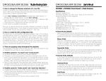
DM2204A Trouble Shooting Guide
DM2204A User’s Manual
1. How to configure the board for different operation modes.
Specifications
When running the QuikWave32 program to assembly sound files, you can configure
the operation modes there. The configuration data is saved in the first EPROM
image file. On powerup the board reads the data and configure itself accordingly.
Some pins on the EPROM chips are bent and not making contact with the socket.
Operation: playback only
Sound File Format: Windows PCM (.wav)
Bit Resolution: 8 bit
Number of Channels: 1 (mono)
Sampling Rate: 6, 8, 11.025, 16, or 22.05 KHz
* All sound files need not have the same sample rate.
Maximum Number of Sound Segments
Direct Mode: 4
Binary Mode: 8
Sequential Mode: 128
Memory Type: EPROM
Capacity: 1 MB (27C080 or equivalent) x 2
Operating Parameters
Supply Voltage: 6, or 9 ~ 12 VDC
Current Consumption: 0.1 A (typical)
Audio Output: 1 W max. (4 Ohm load)
Physical Dimensions: 3.0’’ x 4.2’’
5. Possible causes for “wrong sound”.
Direct Mode
a. The EPROM chips are not inserted in the right order.
b. The board is in the wrong operation mode due to incorrect configuration data.
Re-assemble the sound files with correct configuration data.
Plays up to 4 different sounds. Sound #1 (first priority) is activated by triggering T1,
sound #2 (second priority) by triggering T2, and so on. If multiple triggers are
applied at the same time, only the sound with the highest priority will be played.
6. Possible cause for “trashy sound”.
Binary Mode
Unsupported file formats such as 16-bit resolution, stereo output and ADPCM compression will produce trashy sound. Re-digitize or convert the sound file.
Plays up to 8 different sounds. To activate a certain sound, apply its sound number
(binary code) on T1 (LSB) to T3 (MSB), with “1” = +5V and “0” = 0V. Then trigger T4
to start the playback. The binary code can be removed after the triggering signal
goes back to high (+5V). The binary code for sound #8 is “000”.
2. How to set the sample rate.
There is no need to set the sample rate on the board. The board will read the
information from the EPROM and set the sample rate automatically. All sound files
need not have the same sample rate.
3. Possible causes for “no sound”.
a. The EPROM chips are not programmed properly.
b. The EPROM chips are not inserted in the right order.
c. Some pins on the EPROM chips are bent and not making contact with the socket.
d. The board is in the wrong operation mode due to incorrect configuration data.
Re-assemble the sound files with correct configuration data.
4. Possible cause for “noisy sound”.
7. Possible cause for “sound too fast/slow”.
Unsupported sampling rates will produce sound too fast or too slow. Re-digitize or
convert the sound file.
8. Can the motion sensor trigger any sound?
No. Since the motion sensor output is internally connected to the T1 input, it will
always trigger sound #1 in the Direct mode. It can also trigger all the sounds sequentially in the Sequential mode.
Sequential Mode
Plays up to 128 different sounds. Sounds are played sequentially, one per trigger, by
triggering T1. Sound #1 will be played the first time, sound #2 the second time, and
so on. The sequence starts from #1 again when the next sound is missing.
Interrupt Mode
In this mode, the sound does not start until the trigger goes high. Any sound,
including the sound itself, can interrupt the playback. The playback will be stopped
as soon as the interrupting trigger goes low, but the new sound will not start until
the trigger goes high. Looping is not possible in this mode.
Non-Interrupt Mode
In this mode, the sound starts as soon as the trigger goes low. No sound can
interrupt the playback. A new sound can start only after the current sound is finished. Looping is possible by keeping the trigger low constantly.
DM2204A Installation Guide
Mechanical Drawing (simplified & not to scale)
Power Light (PWR)
The power light should be on when power is applied. However, if input voltage is 6
VDC (jumper J3 set to “6V”), the power light is always off in order to save power.
Volume Pot (VOL)
Turn VOL clockwise to increase the output volume.
Configuration Jumpers
J1, J2 = not used.
J3: (6V) = input voltage is 6 VDC
(12V) = input voltage is 9 ~ 12 VDC
* Caution: The board may be damaged if J3 is not set correctly.
EPROM Programming
Insert the first EPROM chip into socket #1, and the second EPROM chip (if any) into
socket #2. Be sure to insert the EPROM chips with the notched side up, or they may
be damaged.
An EPROM programmer must be used to program EPROM chips, and a UV eraser is
needed to erase EPROM chips in order to re-use them. Before .wav files can be
programmed into EPROM chips, they must be processed by the QuikWave32 program first. The QuikWave32 program combines all the .wav files, along with board
configuration information, into EPROM image files which are then used for EPROM
programming. Depending on the amount of data, one or two EPROM image files
may be generated by the QuikWave32 program. If more than two EPROM image
files are generated, you will need to either reduce the sample rate (to reduce the
amount of data) or use a playback board which has a bigger memory capacity.
Terminal Block (P2) Descriptions
Operation Mode & Sample Rate Configuration
!!! Caution !!!
Power Input: VD & GD
VD is voltage and GD is ground. For 6 V (battery) operation, set jumper J3 to “6V” (top
two pins). For 9 ~ 12 V (DC adaptor) operation, set J3 to “12V” (bottom two pins).
Speaker Output: S1 & S2
The speaker output is bridged. Use 4 Ohm speakers for louder output, 8 Ohm
speakers for less distortion. If external amplification is needed, be sure to use a
power amplifier which accepts bridged (balanced) input. Otherwise the board may
be damaged.
Trigger Inputs: T1 - T4
Either a negative pulse (+5V to ground) or a momentary contact closure with GD
can be used for triggering. Minimum trigger duration is 100 millisecond.
Motion Sensor Connector (P1)
This 4-pin, 0.1” center pin header is for use with an optional SU-20 motion sensor.
The sensor output is internally connected to the board’s T1 trigger input. Therefore
the sensor can be used to trigger either message #1 in the Direct mode, or all
messages (sequentially) in the Sequential mode.
The operation modes are configured in the QuikWave32 program, and the information is stored in the first EPROM image file. Upon power up, the board reads the
information and configure itself accordingly. The sample rate of each .wav file
(each file may have a different sample rate) is automatically detected by the board.
Powerdown Mode
The Powerdown mode may be used to save battery life by reducing the standby
power of the board. However, a small popping sound will be heard at the beginning
and the end of the sound, when the onboard power amplifier is turned on and off.
The Powerdown mode, like the operation modes, is configured in the QuikWave32
program and programmed into the first EPROM chip.
How to Stop a Sound
Since there is no Reset input on the board, it takes some tricks to stop a sound
without starting a new sound. For the Direct and the Binary mode, it is possible only
when the Interrupt mode is enabled, by triggering a non-existing sound. For example, if there are only two sounds in the Direct mode, then triggering T3 or T4 will
stop the current playback. For the Sequential mode, the current sound can be stopped
by triggering any input other than T1.