1
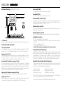
DM2218B Trouble Shooting Guide
DM2218B User’s Manual
1. How to change the filename extension of a .wav file.
Specifications
In order to change the .wav filename extension, you must first force Windows to
show it. Refer to your Windows manual for instruction on how to do it. The following procedure is specific to Windows 2000:
Operation: playback only
Sound File Format: Windows PCM (.wav) 8-bit mono
Sampling Rate: 6, 8, 11.025, 16, or 22.05 KHz
* All sound files need not have the same sample rate.
Maximum Number of Sound Segments
Direct Mode: 8
Binary Mode: 128
Sequential Mode: 128
Memory Type: CompactFlash card (type 1, 5V), 8 ~ 128 MB
Supply Voltage: 6, or 9 ~ 12 VDC
Audio Output: 1 W max. (4 Ohm load), bridged output
Physical Dimensions: 3.0’’ x 4.2’’
a. Select Start > Settings > Control Panel and double click “Folder Options”. In
Windows 98, the “Folder Options” is under Start > Settings.
b. Click the “File Types” tab, scroll down the list to find the “WAV” extension, highlight it and click “Advanced” (click “Edit” if in Windows 98).
c. Check the box for “Always show extension” and click “OK”.
d. Click “Close” to complete the procedure.
Now you can right-click the file icon and select “Rename” to rename it. If you get a
warning message saying “If you change a filename extension, the file may become
unusable. Are you sure you want to change it?”, click “Yes”.
2. How to create the CFG (configuration) file.
The easiest way is to use NotePad (a Windows accessory). Type in the configuration
letters and use “Save As” to save the file. In the “Save As” window, select the
proper folder for “Save in”, select “All Files” for “Save as type”, and enter “???.CFG”
for “File name” (where ??? can be any name with up to 8 letters). Certain versions
of NotePad also have an “Encoding” section for which you should select “ANSI”.
The CFG file should then be copied onto the CF card. If the CFG file is missing or
incorrect, the board will operate in the DN mode.
Direct Mode (default)
Plays up to 8 different sounds. Sound #1 (first priority) is activated by triggering
T1, sound #2 (second priority) by triggering T2, and so on. If multiple triggers are
applied at the same time, only the sound of the highest priority will be played.
Binary Mode
Plays up to 128 different sounds. To activate a certain sound, apply its file ID
number on T1 (LSB) to T7 (MSB), with “1” = +5V and “0” = 0V. Then pulse T8 low
to start the playback. The file ID number can be removed after the triggering
pulse returns to high (+5V). The file ID number for sound #128 is “0000000”.
3. Should the files be copied to the CF card in a certain order?
Sequential Mode
No. The files, including the CFG file, can be copied to the CF card in any order.
Plays up to 128 different sounds. Sounds are activated sequentially by triggering
T1. Sound #1 is played the first time, sound #2 the second time, and so on. The
sequence starts from #1 again when the next sound is absent.
4. Possible causes for “no sound” and “wrong sound”.
a. The sound file doesn’t have the correct filename extension.
b. The board is in the wrong operation mode due to missing/incorrect CFG file.
c. If the CF card is inserted when the power is on, the board will not work. To solve
this problem, turn the power off for a few seconds. If this action does not fix the
problem, make sure the sound files are still on the CF card.
d. Some CF cards, especially if they have been used in digital cameras, have a nonstandard format which can not be read by the board. In this case, re-format the
CF card to the standard DOS FAT format and copy the .wav files again.
5. Possible cause for “trashy sound”.
Unsupported file formats such as 16-bit resolution, stereo output and ADPCM compression will produce trashy sound. Re-digitize or convert the sound file.
6. Possible cause for “sound too fast/slow”.
Unsupported sampling rates will produce sound too fast or too slow. Re-digitize or
convert the sound file.
Normal Mode (default)
In this mode, the sound starts as soon as the trigger goes low. No sound can
interrupt the playback. A new sound can start only after the current sound is
finished. Looping is possible by keeping the trigger low constantly.
Interrupt Mode
In this mode, the sound does not start until the trigger goes high. Any sound,
including the sound itself, can interrupt the playback. The playback will be stopped
as soon as the interrupting trigger goes low, but the new sound will not start
until the trigger goes high. Looping is not possible in this mode.
Hold Mode
In this mode, the sound plays only for as long as the trigger is held low. The
playback is not interruptable. Looping is possible in this mode.
DM2218B Installation Guide
Mechanical Drawing (simplified & not to scale)
Power Light (PWR)
The power light should be on when power is applied.
Volume Pot (VOL)
Turn VOL clockwise to increase the output volume.
Alternate Signal Connector (P2)
This 12-pin, 0.1” center pin header can be used as an alternate signal connector
instead of the terminal block. However, it does not carry the speaker output. Pins
from top to bottom are VD, GD, BY, RS, T1~T8.
Alternate Power Jack (P6)
This 2.1 mm, center positive coax jack can be used as an alternate power connector
instead of the terminal block.
Alternate Speaker Jack (P7)
This 3.5 mm mono phone jack provides single ended output up to 0.25W max.
Configuration Jumpers
!!! Caution !!!
Always turn off the power before inserting the CF card, or the board will not work.
Terminal Block (P4) Descriptions
Power Input: VD & GD
VD is voltage and GD is ground. For 6 V (battery) operation, set jumper J3 to “6V” (top
two pins). For 9 ~ 12 V (DC adaptor) operation, set J3 to “12V” (bottom two pins).
Speaker Output: S1 & S2
The speaker output is a balanced output. Use a low impedence speaker (4~8 Ohm).
If external amplification is needed, use either this balanced output or the unbalanced output from P7 depending on the external amplifier’s input type.
Busy Output: BY (available on connector P2 only)
BY is an open-collector output with 100 mA current sink capability. It is activated
during the entire playback period of any sound. To use it to control a relay, connect
the relay coil’s positive pin to the supply voltage and the negative pin to BY. Note
that the relay coil’s voltage rating must be the same as the supply voltage. If a logic
high/low level is needed, a 10K pull-up resistor must be added.
Reset Input: RS (available on connector P2 only)
Connect RS to ground to reset the board. Minimum reset duration is 100 ms.
Trigger Inputs: T1 - T8
Either a negative pulse (+5V to ground) or a momentary contact closure with GD
can be used for triggering. Minimum trigger duration is 100 millisecond.
J1: (1,2) = normal power, (2,3) = low power
If low power is selected, a popping noise will be heard when the sound starts/stops.
J2: not used.
J3: (6V) = input voltage is 6 VDC
(12V) = input voltage is 9 ~ 12 VDC
* Caution: The board may be damaged if J3 is not set correctly.
CompactFlash Card Programming
A CompactFlash (CF) card reader must be used to read and write CF cards. Simply
write the sound (.wav) files to the CF card. However, you must change the “.wav”
filename extension to a 3-digit number. For example, “lion.001” indicates that it’s
sound #1 and “frog.128” is sound #128. The order in which these files are written
to the card is not important. Files with invalid filename extension are ignored.
Operation Mode & Sample Rate Configuration
To select the desired operation modes, you must copy to the CF card an ASCII text
file named “???.CFG” (??? can be any name with up to 8 letters) which contains
one and only one of the following two letter word:
DI (Direct, Interrupt)
BI (Binary, Interrupt)
SI (Sequential, Interrupt)
DN (Direct, Non-Interrupt)
BN (Binary, Non-Interrupt)
SN (Sequential, Non-Interrupt)
If the CFG file is missing or incorrect, the board will operate in the DN mode. The
CFG file is read by the board upon power up and after reset.
The sound file’s sample rate is automatically detected by the board.